

Page 1

Remote Camera
Operating Switcher
Operating Instructions
Before operating the unit, please read this manual thoroughly
and retain it for future reference.
BRS-200
4-145-707-11 (1)
© 2009 Sony Corporation
BRS-200
Sony Corporation
Printed in Japan
Page 2

Owner’s Record
The model and serial numbers are located on the bottom.
Record these numbers in the spaces provided below.
Refer to these numbers whenever you call upon your Sony
dealer regarding this product.
Model No.
Serial No.
5.Install the equipment while taking the operating
temperature of the equipment into consideration
For the operating temperature of the equipment, refer to
the specifications of the Operation Manual.
6.When performing the installation, keep the following
space away from walls in order to obtain proper
exhaust and radiation of heat.
Right, Left : 10 cm (4 inches) or more
WARNING
To reduce the risk of fire or electric shock,
do not expose this apparatus to rain or
moisture.
To avoid electrical shock, do not open the
cabinet. Refer servicing to qualified
personnel only.
WARNING
THIS APPARATUS MUST BE EARTHED.
WARNING
The supplied AC power adaptor has no power switch.
When installing the unit, incorporate a readily accessible
disconnect device in the fixed wiring, or connect the power
plug to an easily accessible socket-outlet near the unit. If
a fault should occur during operation of the unit, operate
the disconnect device to switch the power supply off, or
disconnect the power plug.
Attention-when the product is installed in Rack:
1.Prevention against overloading of branch circuit
When this product is installed in a rack and is supplied
power from an outlet on the rack, please make sure that the
rack does not overload the supply circuit.
2.Providing protective earth
When this product is installed in a rack and is supplied
power from an outlet on the rack, please confirm that the
outlet is provided with a suitable protective earth
connection.
When installing the installation space must be secured in
consideration of the ventilation and service operation.
• Do not block the ventilation slots at the left side and right
side panels, and vents of the fans.
• Leave a space around the unit for ventilation.
• Leave more than 10 cm (4 inches) of space in the rear of
the unit to secure the operation area.
When the unit is installed on the desk or the like, leave at
least 10 cm (4 inches) of space in the left and right sides.
Leaving 10 cm (4 inches) or more of space above the unit
is recommended for service operation.
IMPORTANT
The nameplate is located on the bottom.
For the customers in the U.S.A.
This equipment has been tested and found to comply with
the limits for a Class A digital device, pursuant to Part 15
of the FCC Rules. These limits are designed to provide
reasonable protection against harmful interference when
the equipment is operated in a commercial environment.
This equipment generates, uses, and can radiate radio
frequency energy and, if not installed and used in
accordance with the instruction manual, may cause
harmful interference to radio communications. Operation
of this equipment in a residential area is likely to cause
harmful interference in which case the user will be
required to correct the interference at his own expense.
You are cautioned that any changes or modifications not
expressly approved in this manual could void your
authority to operate this equipment.
All interface cables used to connect peripherals must be
shielded in order to comply with the limits for a digital
device pursuant to Subpart B of Part 15 of FCC Rules.
3.Internal air ambient temperature of the rack
When this product is installed in a rack, please make sure
that the internal air ambient temperature of the rack is
within the specified limit of this product.
4.Prevention against achieving hazardous condition
due to uneven mechanical loading
When this product is installed in a rack, please make sure
that the rack does not achieve hazardous condition due to
uneven mechanical loading.
2
This device complies with Part 15 of the FCC Rules.
Operation is subject to the following two conditions: (1)
this device may not cause harmful interference, and (2) this
device must accept any interference received, including
interference that may cause undesired operation.
For customers in Canada
This Class A digital apparatus complies with Canadian
ICES-003.
Page 3

For kundene i Norge
Dette utstyret kan kobles til et IT-strømfordelingssystem.
For the customers in Europe, Australia and New
Zealand
WARNING
This is a Class A product. In a domestic environment, this
product may cause radio interference in which case the
user may be required to take adequate measures.
For the customers in Europe
The manufacturer of this product is Sony Corporation, 17-1 Konan, Minato-ku, Tokyo, Japan.
The Authorized Representative for EMC and product
safety is Sony Deutschland GmbH, Hedelfinger Strasse
61, 70327 Stuttgart, Germany. For any service or
guarantee matters please refer to the addresses given in
separate service or guarantee documents.
This apparatus shall not be used in the residential area.
3
Page 4

Precautions
Operating and Storage Locations
• Avoid operating and storing the switcher in the
following locations:
– Extremely hot or cold places (operating temperature:
5°C to 40°C (41°F to 104°F)
– Places exposed to direct sunlight for a long period or
close to heating appliances
– Close to sources of strong magnetism
– Close to sources of powerful electromagnetic
radiation, such as radios or TV transmitters
– Places exposed to strong vibration or shock
• Using a mobile phone, etc. near the switcher may cause
a malfunction or affect the images. Try to turn off mobile
phones, etc. as much as possible when you are near the
switcher.
• When the switcher is installed in a rack, leave more than
10 cm (4 inches) of space at the left and right sides and
more than 10 cm (4 inches) of space in the rear between
the rack and the switcher.
• Leave space around the switcher for ventilation and
maintenance when it is installed.
– Do not obstruct ventilation openings at the left and
right sides of the Processor Unit.
– Leave spaces around the switcher for ventilation.
– Leave more than 10 cm (4 inches) of maintenance
clearance at the rear of the switcher.
– When the switcher is installed on a horizontal position
such as on a desk, leave more than 10 cm (4 inches) of
space at the left and right sides. Leaving more than 10
cm (4 inches) of space above the switcher is
recommended for service operation.
Cleaning
Make sure to disconnect the power plug of the switcher
from the AC outlet before cleaning.
On cleaning of the cabinet
• Use a soft, dry cloth to gently wipe the cabinet. Stubborn
stains may be removed with a cloth lightly dampened
with a mild detergent solution. Then wipe it with a soft
dry cloth.
• Never use strong solvent, such as thinner, benzene, or
insecticides, since they may damage the surface finish or
fade indications on the switcher.
• If you wipe the cabinet forcibly using a cloth with any
dust attached, the cabinet may be scratched.
• If the cabinet of the switcher is exposed to a rubber or
vinyl object for a long period, the cabinet may be
changed in quality, or some of the coating may come off.
4
Page 5

Table of Contents
Precautions ......................................................................................4
Chapter 1 Overview
Features............................................................................................9
System Configuration ...................................................................10
Structure of Switched or Composed Video Output by Video
Operating and Storage Locations .......................................................... 4
Cleaning................................................................................................. 4
Basic Configuration............................................................................. 10
Configuration for a Live Event ........................................................... 11
Configuration for a Presentation ......................................................... 12
Configuration for Presentation Using Two Projectors ........................ 13
Switching .................................................................................14
Chapter 2 Locations and Functions of Parts
Control Panel .................................................................................15
1 Mode Buttons ................................................................................ 16
2 CAMERA/DSK/AUX Bus Section............................................... 17
3 Cross-Point Bus Section ................................................................ 19
4 Effect Transition Section............................................................... 20
5 Menu/Snapshot/Camera Position Section ..................................... 21
6 Display Panel / Camera/Switcher/Menu Control Section ............. 23
7 Camera Menu/Location Control Section....................................... 26
8 Joystick .......................................................................................... 27
9 Rear Panel Section......................................................................... 28
Processor Unit ...............................................................................29
Front Panel .......................................................................................... 29
Rear Panel............................................................................................ 29
BRSA-20HSD1 HD/SD-SDI Input Board (Not Supplied) ................. 31
BRSA-20DD1 DVI Input Board (Not Supplied) ................................ 31
BRSA-20DD2 DVI Output Board (Not Supplied).............................. 31
Chapter 3 Preparations
Connecting External Equipment ..................................................33
Connecting VISCA Cameras............................................................... 34
Connecting a Video Output Device Such as a Camera Other Than a
BRC-Series Camera ................................................................... 36
Table of Contents
5
Page 6

Connecting a DVI Signal Output Device ............................................ 36
Connecting Monitors to the PGM1 And PGM2 Connectors .............. 37
Connecting Monitors to the AUX1 And AUX2 Connectors .............. 37
Connecting a Monitor or Projector Equipped with a DVI Input......... 38
Connecting a Computer for Storing the Setting Data.......................... 38
Connecting an External Sync Signal ................................................... 39
Installation and Connection of the Switcher...............................40
Installing an Interface Board ............................................................... 40
Connecting the Processor Unit and Control Panel .............................. 42
Turning on the Power .......................................................................... 45
Menu Operation .............................................................................46
Displaying the Menus.......................................................................... 46
Operating the Menu............................................................................. 48
Basic Setups for the Switcher......................................................50
Setting the Video Signal Format and Aspect Ratio (Menu Page
951) ............................................................................................ 50
Setting Up the Video Input Signals..................................................... 51
Setting Up the Video Output Signals .................................................. 54
Setting the Bus Mode for the Cross-Point Buttons (Menu Page
943) ............................................................................................ 56
Setting Up the VISCA Camera ........................................................... 57
Setting Up the Switcher for Connecting the Computer (Menu Page
963) ............................................................................................ 60
Chapter 4 Switching Operation
Before Starting the Switching Operation ....................................63
Enabling SW Mode ............................................................................. 63
Selecting the Auxiliary Output Video ................................................. 64
Basics of Video Switching............................................................65
Switching the Video with a Cut ....................................................66
Switching Directly with the PGM Select Button ................................ 66
Switching with the CUT Button After Checking the Next Video in the
Preview Window........................................................................ 67
Switching the Video with an Effect (Transition Effect) ..............69
Switching the Video with a Dissolve Effect (Mix) ............................. 71
Switching the Video with a Wipe........................................................ 72
Composing Videos Using Picture-in-Picture (PIP) .....................75
Executing Picture-in-Picture .............................................................. 76
Adjusting the Size and Display Position of an Embedded Video in
Picture-in-Picture ....................................................................... 77
Setting the Transition Time ..........................................................80
Setting a Border for a Wipe or PIP ...............................................81
Using the Color Bars or Color Mattes..........................................82
Assigning the Color Bar or Color Matte to the PGM or NEXT Select
Button......................................................................................... 82
Changing the Color of Color Matte..................................................... 82
6
Table of Contents
Page 7

Using Still Images Stored in Frame Memory...............................83
Using the Downstream Key (DSK) to Add Characters or
Graphics ..................................................................................85
Composing Video Using the Luminance Key..................................... 87
Composing Video Using DSK Split.................................................... 88
Composing Video Using the Chroma Key.......................................... 91
Checking the Results of Composite Video (Effect Preview) .....96
Storing the Settings of a Wipe, PIP, and Setting Menu Items ...97
Chapter 5 VISCA Camera Operations
Before Operating the Camera.....................................................101
Setting the Switcher to CAM mode .................................................. 102
Selecting the Camera to Be Controlled ............................................. 103
Controlling the Camera ...............................................................104
Adjusting the Focus of the Camera ................................................... 104
Adjusting the Exposure ..................................................................... 105
Adjusting the White Balance............................................................. 107
Zooming ............................................................................................ 108
Operating Pan/Tilt of the Camera ..................................................... 109
Storing the Camera Settings ......................................................111
Operating the Camera Menu.......................................................114
Disabling the Infrared Remote Commander Supplied with the
Camera...................................................................................116
Setting the Illumination of the Tally Lamp on the Camera ......117
Chapter 6 Control Using External Devices
Using the GPI I/O Connector ......................................................119
Assigning Various Functions to the Pins on the GPI I/O Connector 119
Control Examples Using the GPI I/O Connector .............................. 121
Using the REMOTE Connector ...................................................123
Configuring SERIAL DATA ............................................................ 123
Command .......................................................................................... 124
Transferring Data between the Switcher and a Computer.......125
Connection and Configuration ......................................................... 125
Downloading/Uploading ................................................................... 125
Appendix
Menu List ......................................................................................131
Camera Mode Menu.......................................................................... 132
Switcher Mode Menu ........................................................................ 132
Table of Contents
7
Page 8

MEM Menu ....................................................................................... 133
WIPE Menu....................................................................................... 133
MATT Menu ..................................................................................... 134
DSK Menu......................................................................................... 134
PIP Menu........................................................................................... 135
SETUP Menu .................................................................................... 136
Conversion between Input Signal and Output Signal.............. 142
Messages and Troubleshooting.................................................144
Installing the Rack Mounting Bracket into the Switcher.......... 145
Specifications ..............................................................................146
Pin Assignments ................................................................................ 148
Wiring Example of VISCA RS-422 Connection .............................. 150
To Use the VISCA RS-422 Connector Plug ..................................... 151
Acceptable DVI-I Input/Output Signal Formats ............................... 152
Dimensions ..................................................................................153
Control Panel..................................................................................... 153
Processor Unit ................................................................................... 154
Glossary .......................................................................................155
Index ............................................................................................157
8
Table of Contents
Page 9

Overview
Features
The Sony Remote Camera Operating Switcher is a compact switcher,
incorporating functions for controlling up to seven BRC-series cameras, and
video switching functions that support HD signals.
Flexible input/output configuration
Optional interface boards can be installed in the switcher, and a combination of
these interface boards allows you to accept various inputs according to your
requirements. An input of DVI signal and eight inputs of SDI signal, up to nine
inputs in total, can be enabled.
The switcher is equipped with four SDI outputs of three channels and one DVI
output as standard. Installing the optional interface board provides one
additional DVI output, allowing you to project different video sources on two
monitors or projectors. This provides wider usage of the switcher for various
events and presentations.
Chapter
Chapter 1 Overview
1
Basic video switching features incorporated
This switcher is of compact type but is equipped with basic HD signal switching
features, such as mix, wipe, PIP (Picture-in-Picture) and DSK (Down Stream
Key). It is also equipped with a dedicated SD signal switching mode that can be
switched by menu operation.
Minimized video latency
Thanks to 1-line minimized video latency of the switcher when a genlock signal
is applied, the switcher is suitable for use for conferences, live events, etc.
Multi-viewer
The switcher incorporates a multi-viewer function that enables display of 4, 10
or 16 different programs on one monitor at the same time with 4-, 10- or
16-picture split screens.
Features
9
Page 10
System Configuration
Chapter 1 Overview
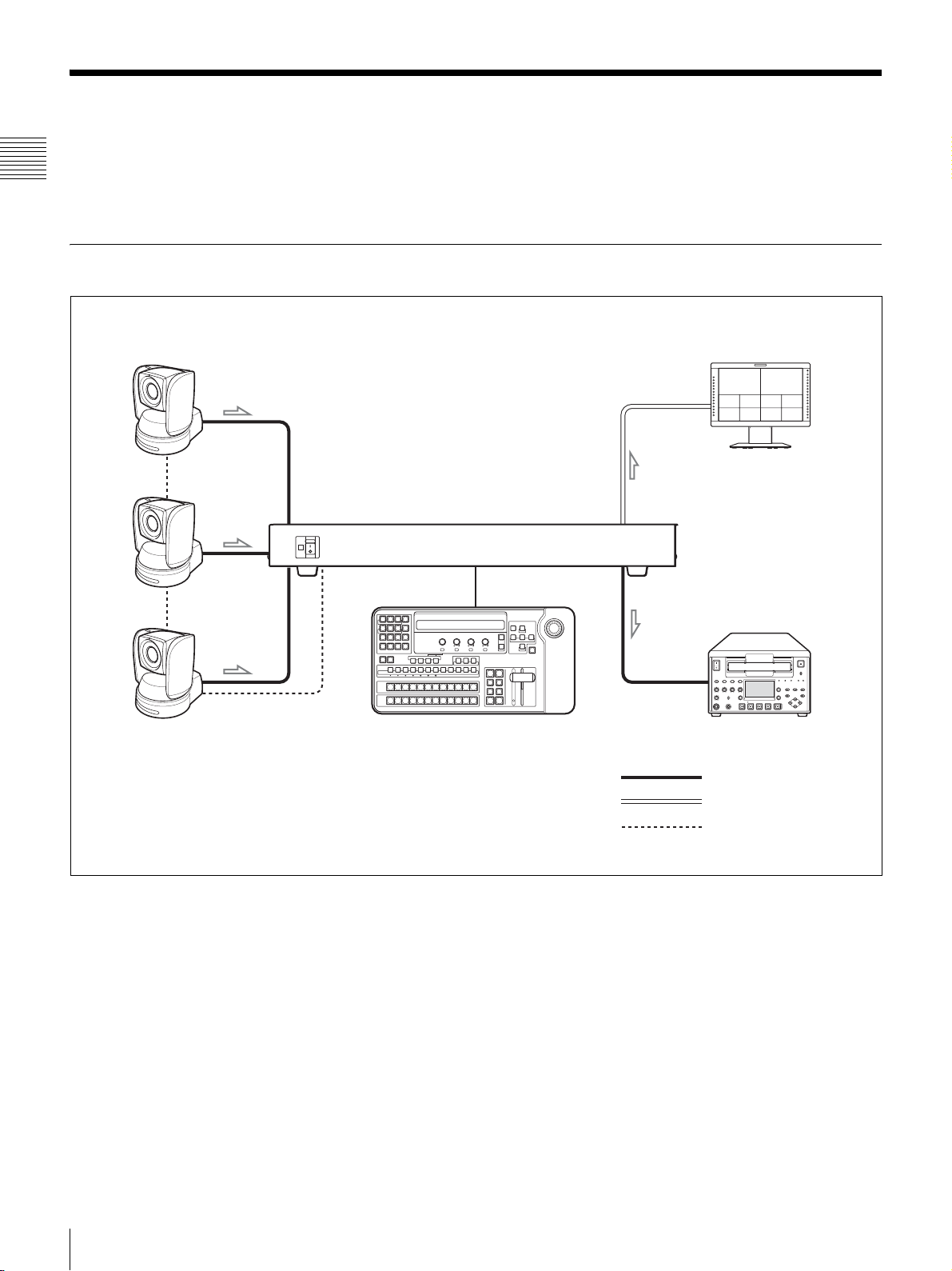
Basic Configuration
The BRS-200 Remote Camera Operating Switcher has various system
capabilities with the use of optional equipment. This section describes typical
four system configurations.
BRC-series cameras with the HD-SDI
output card attached
SDI IN 3
SDI IN 2
SDI IN 1
ON
OFF
POWER
RS-232C
89
MENU
7
DSK PIP SETUP
DIRECT
456
RECALL
MEM
WIPE MATT
123
0.
MENU/SNAP
CAM
CAMERA
DSK/AUX
PGM
NEXT
FOCUS BRIGHT ZOOM PAN/TILT
PRESET
NEAR FAR
CLEAR RECALL
SHOT/CAMERAPOSITION
SW
123456789101112
LOW HIGH PRESET SPEED
1
123456789101112
F1 F2 F3 F4
AUTO/MANUAL
P/T RST
PST SPD
O P AF
DSK
PIP
AUX 1
AUX 2
CAMERA
23456789101112
900 t 910 t 911 t 912
Control cable
(supplied)
BRS-200
REMOTE CAMERA OPERATING SWITCHER
CAMERA
MENU
UP
FINE
RIGHT
LEFTXENTER
EXIT
Z
Y
DOWN
CENTER
PAGE
O P AWB
BK LIGHT
SPT LIGHT
PGM
PVW
MV
CAM
DSK
PIP
AUTO
AUTO
N/R
REV
MX
WIPE
AUTO
CUT
TRANS
Monitor with the multi-viewer
feature (LMD-series monitor, etc.)
...
918
DVI-I OUT
PGM1
Recorder (HVR-1500A, etc.)
HD-SDI cable
+
–
+
–
+
–
+
–
+
–
+
–
10
System Configuration
DVI cable
RS-232C VISCA cable
Page 11

Configuration for a Live Event
Camcorder equipped with the HD-SDI output
(PVM-series video cameras, etc.)
D
L
O
H
L
J
/S
ls
G
j
W
T
B
A
Monitor for previewing
(LMD-series monitors,
etc.)
SDI IN 4
SDI IN 3
SDI IN 2
SDI IN 1
ON
OFF
POWER
RS-232C
Monitor for
programming
(LMD-series monitors,
etc.)
+
–
+
–
+
–
+
–
+
–
+
–
AUX1 PGM2
Control cable
(supplied)
89
MENU
7
DSK PIP SETUP
DIRECT
456
RECALL
WIPE MATT
MEM
123
0.
MENU/SNAP
CAM
CAMERA
DSK/AUX
PGM
NEXT
FOCUS BRIGHT ZOOM PAN/TILT
PRESET
NEAR FAR
CLEAR RECALL
SHOT/CAMERAPOSITION
SW
123456789101112
LOW HIGH PRESET SPEED
1
123456789101112
F1 F2 F3 F4
AUTO/MANUAL
O P AF
P/T RST
PST SPD
DSK
AUX 2
PIP
AUX 1
CAMERA
23456789101112
O P AWB
BK LIGHT
SPT LIGHT
PGM
PVW
BRS-200
REMOTE CAMERA OPERATING SWITCHER
CAMERA
MENU
UP
FINE
RIGHT
LEFTXENTER
EXIT
Z
Y
DOWN
CENTER
PAGE
MV
CAM
DSK
PIP
AUTO
AUTO
N/R
REV
MX
WIPE
AUTO
CUT
TRANS
Monitor for multi-viewing
(LMD-series monitors, etc.)
+
–
+
–
+
–
+
–
+
–
+
–
AUX2
PGM1
Chapter 1 Overview
+
–
+
–
+
–
+
–
+
–
+
–
BRC-series cameras with the
HD-SDI output card attached
Recorder (HVR-1500A, etc.)
HD-SDI cable
RS-232C VISCA cable
System Configuration
11
Page 12
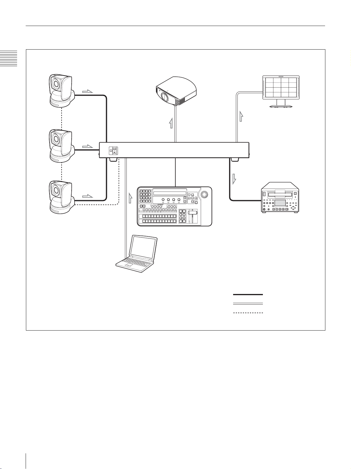
Configuration for a Presentation
Chapter 1 Overview
BRC-series cameras with the
HD-SDI output card attached
Projector for projecting the program
image on the screen
900 t 910 t 911 t 912
Monitor for multi-viewing
(LMD-series monitors, etc.)
...
918
+
–
+
–
+
–
+
–
+
–
+
–
SDI IN 3
DVI-I OUT on the
SDI IN 2
SDI IN 1
BRSA-20DD2*
ON
OFF
POWER
DVI-I IN on the
BRSA-20DD1*
DVI-I OUT
PGM1
Control cable
(supplied)
BRS-200
REMOTE CAMERA OPERATING SWITCHER
CAMERA
MENU
UP
FINE
RIGHT
LEFTXENTER
EXIT
Z
Y
DOWN
CENTER
PAGE
MV
CAM
DSK
PIP
AUTO
AUTO
N/R
REV
MX
WIPE
AUTO
CUT
TRANS
Recorder (HVR-1500A, etc.)
RS-232C
89
MENU
7
DSK PIP SETUP
DIRECT
456
RECALL
MEM
WIPE MATT
123
0.
MENU/SNAP
CAM
CAMERA
DSK/AUX
PGM
NEXT
FOCUS BRIGHT ZOOM PAN/TILT
PRESET
NEAR FAR
CLEAR RECALL
SHOT/CAMERAPOSITION
SW
123456789101112
LOW HIGH PRESET SPEED
1
123456789101112
F1 F2 F3 F4
AUTO/MANUAL
P/T RST
PST SPD
O P AF
DSK
PIP
AUX 1
AUX 2
CAMERA
23456789101112
O P AWB
SPT LIGHT
BK LIGHT
PVW
PGM
*
Optional interface board
Computer for importing
presentation materials
HD-SDI cable
DVI cable
RS-232C VISCA cable
12
System Configuration
Page 13
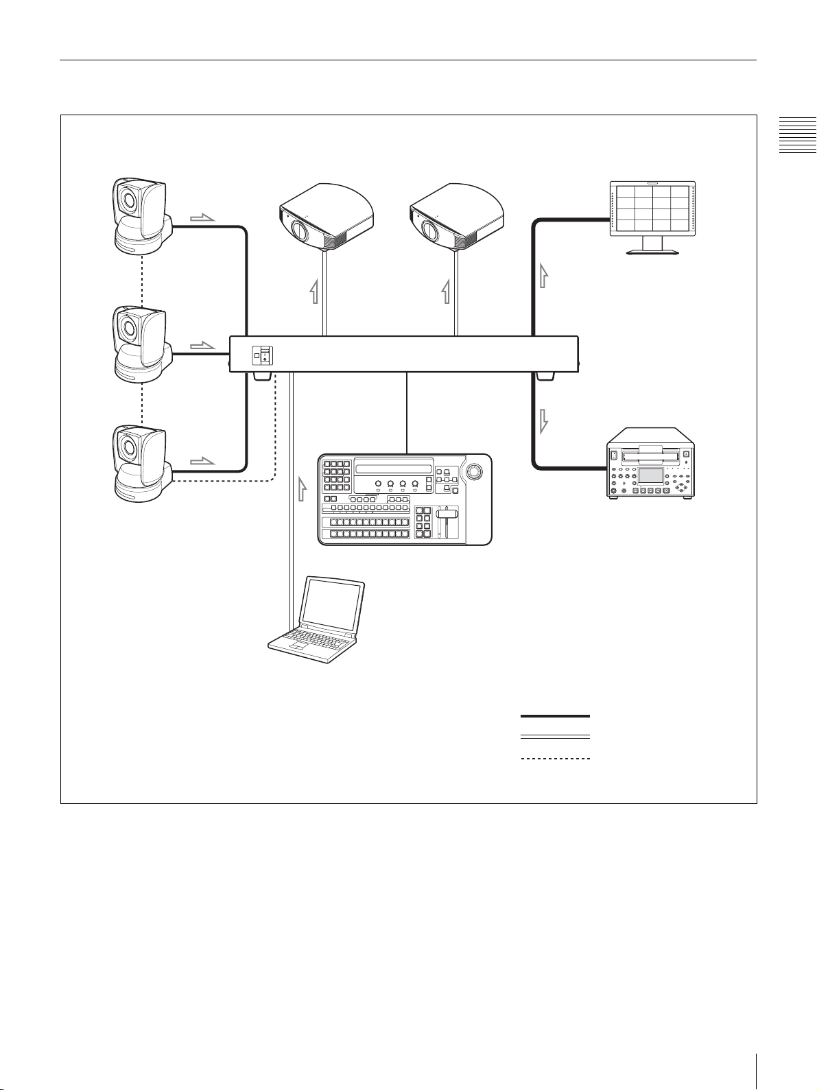
Configuration for Presentation Using Two Projectors
BRC-series cameras with the
HD-SDI output card attached
SDI IN 3
SDI IN 2
SDI IN 1
RS-232C
Projector for projecting
presentation materials
from a computer
ON
OFF
POWER
DVI-I IN on the
BRSA-20DD1
7
DSK PIP SETUP
456
MEM
WIPE MATT
123
0.
MENU/SNAP
CAM
SW
CAMERA
DSK/AUX
LOW HIGH PRESET SPEED
PGM
NEXT
DVI-I OUT on the
BRSA-20DD2
*
*
89
MENU
DIRECT
RECALL
FOCUS BRIGHT ZOOM PAN/TILT
PRESET
NEAR FAR
CLEAR RECALL
SHOT/CAMERAPOSITION
123456789101112
1
123456789101112
F1 F2 F3 F4
SPT LIGHT
BK LIGHT
AUTO/MANUAL
P/T RST
PST SPD
O P AF
DSK
PIP
AUX 1
AUX 2
PVW
PGM
CAMERA
23456789101112
O P AWB
MV
Projector for projecting
the program images on
the screen
DVI-I OUT
Control cable
(supplied)
BRS-200
REMOTE CAMERA OPERATING SWITCHER
CAMERA
MENU
UP
FINE
RIGHT
LEFTXENTER
EXIT
Z
Y
DOWN
CENTER
PAGE
CAM
DSK
PIP
AUTO
AUTO
N/R
REV
MX
WIPE
AUTO
CUT
TRANS
Monitor for multi-viewing
(LMD-series monitors, etc.)
AUX1
PGM1
Recorder (HVR-1500A, etc.)
Chapter 1 Overview
+
–
+
–
+
–
+
–
+
–
+
–
*
Optional interface board
Computer for impoting
presentation materials
HD-SDI cable
DVI cable
RS-232C VISCA cable
System Configuration
13
Page 14

Structure of Switched or Composed Video Output by Video Switching
Chapter 1 Overview
B
Background video
Foreground video
F
PIP video
The structure of the images to be switched or composed
by video switching is shown above.
For the detailed operations, see Chapter 4 “Switching
Operation.”
Background video
The background video is an image before you apply an
effect such as wipe and mix. This can also be expressed
as an image that disappears as the effect progresses.
Select the background video with PGM select buttons 1
to 12.
Foreground video
The foreground video is an image to be inserted by
applying an effect such as wipe or mix. This can also be
expressed as an image that appears as the effect
progresses and is switched with the background video.
Select the foreground video with NEXT select buttons 1
to 12 and perform the effect, using the transition lever or
the AUTO TRANS button.
PIP (Picture-in-Picture) video
The PIP video is an image to be inserted over a
background video (and a foreground video while the
effect is being applied).
Select the PIP video by pressing the PIP button and DSK/
AUX 1 to 12 buttons. To compose the PIP video, press
the PIP AUTO button.
DSK FILL (Downstream key fill) video
The DSK FILL video is an image to be composed actually
by DSK composition.
P
DSK FILL video
DSK SOURCE video
Program video
B
P
F
Select the DSK FILL video by pressing the DSK button
and DSK/AUX 1 to 12 buttons. To compose the DSK
FILL video, press the DSK AUTO button.
DSK SOURCE (Downstream key source) video
The DSK SOURCE video is an image to determine the
area of a DSK FILL video to be composed. This is also
referred to as a “key.”
There are three types of keys:
• Luminance key that cuts a key portion of a DSK FILL
video using a key signal (DSK SOURCE) created by a
specific brightness of the DSK FILL video.
• Chroma key that cuts a key portion of a DSK FILL
video using a key signal (DSK SOURCE) created by a
specific color of the DSK FILL video.
• Split function that cuts a key portion of a DSK FILL
video using a key signal created by a specific brightness
of the DSK SOURCE video selected separated from the
DSK FILL video.
Note
The DSK FILL video and the DSK SOURCE video are
identical for the luminance key and chroma key.
Program video
The program video is an image output from the switcher
after switching or composition was applied.
14
Structure of Switched or Composed Video Output by Video Switching
Page 15
Locations and Functions
of Parts
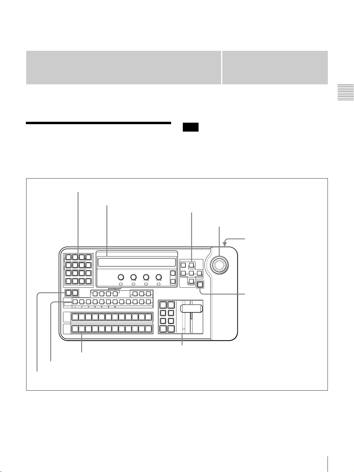
Control Panel
The parts on the control panel are grouped into 1 to 9
according to their functions, as shown below. See the
pages in parentheses for more details.
5 Menu/snapshot/camera position section (page 21)
6 Display panel / camera/switcher/
menu control section (page 23)
Chapter
2
Note
You can set for a warning beep to sound if the switcher is
incorrectly operated. Set “BEEP” to “On” on menu page
944 to enable the beep sound (page 139).
7 Camera menu/location control section (page 26)
8 Joystick
9 Rear panel (page 28)
Chapter 2 Locations and Functions of Parts
89
7
DSK PIP SETUP
456
MEM
123
0.
MENU/SNAP
CAM
CAMERA
DSK/AUX
PGM
NEXT
MENU
DIRECT
RECALL
WIPE MATT
PRESET
CLEAR RECALL
SHOT/CAMERA POSITION
P/T RST
PST SPD
SW
123456789101112
LOW HIGH PRESET SPEED
1
2 3 4 5 6 7 8 9 10 11 12
123456789101112
CAMERA
AUTO/MANUAL
PIP
AUX 1
DSK
3 Cross-point bus section (page 19)
2 CAMERA/DSK/AUX bus section (page 17)
1 Mode buttons (page 16)
FOCUS BRIGHT ZOOM PAN/TILT
NEAR FAR
F1 F2 F3 F4
BK LIGHT
SPT LIGHT
O P AF
AUX 2
O P AWB
PGM
PVW
MV
DSK
AUTO
N/R
AUTO
TRANS
BRS-200
REMOTE CAMERA OPERATING SWITCHER
CAMERA
UP
MENU
FINE
LEFTXENTER
RIGHT
EXIT
PAGE
DOWN
CENTER
Y
Z
CAM
1 Mode button (page 16)
PIP
AUTO
REV
WIPE
MX
CUT
4 Effect transition section (page 20)
Control Panel
15
Page 16

1 Mode Buttons
The buttons and controls on the switcher function
according to the mode switched between CAM (camera)
mode and SW (switcher) mode with the mode buttons.
Chapter 2 Locations and Functions of Parts
0.
MENU/SNAP
CAM
1 CAM (camera) mode button
CLEAR RECALL
SHOT/CAMERA POSITION
SW
P/T RST
DSK
PST SPD
PIP
AUTO/MANUAL
2 SW (switcher) mode button
AUX 1
O P AF
AUX 2
Note
The function modes of the switcher consist of CAM
(camera) mode, SW (switcher) mode and menu mode. To
switch the switcher to menu mode, press the MENU button
in 5 Menu/snapshot/camera position section (page 21).
NEAR FAR
F1 F2 F3 F4
SPT LIGHT
PVW
O P AWB
BK LIGHT
PGM
DOWN
PAG E
MV
CENTER
CAM
1 CAM (camera) mode button
a CAM (camera) mode buttons
Press one of these buttons to use the 2 CAMERA/DSK/
AUX bus section, 5 Menu/snapshot/camera position
section, 6 Display panel / camera/switcher/menu control
section, 7 Camera menu/location control section or 8
Joystick to control connected cameras.
The CAM mode buttons on the left and right sides function
the same.
You can control the cameras when the CAM mode buttons
are lit.
b SW (switcher) mode button
Press this button to use the 2 CAMERA/DSK/AUX bus
section, 5 Menu/snapshot/camera position section, 6
Display panel / camera/switcher/menu control section, 7
Camera menu/location control section or 8 Joystick to
control the video switcher.
You can control the video switcher when the SW mode
button is lit.
Note
The buttons in the 3 Cross-point bus section and 4
Effect transition section function for video switching even
when the switcher is in a mode other than SW mode.
16
Control Panel
Page 17

2 CAMERA/DSK/AUX Bus Section
The buttons in this section differ in function depending on
whether the switcher is in CAM mode or SW mode.
5 O P AF button / AUX 2 button
4 AUTO/MANUAL button / AUX 1 button
3 PST SPD button / PIP button
2 P/T RST button / DSK button
P/T RST
DSK
CAMERA
PST SPD
PIP
CAM
SW
CAMERA
DSK/AUX
123456789101112
LOW HIGH PRESET SPEED
1 CAMERA buttons / DSK/AUX buttons
x Functions in CAM mode
a CAMERA buttons
Selects the connected camera to be controlled. The
selected camera button lights up.
To set up the selected camera, use the SETUP menu.
For details on setup of the camera, see “Setting Up the
VISCA Camera” on page 57.
Note
Assign the VISCA cameras (BRC-300/300P, BRC-H700,
BRC-Z700 and BRC-Z330) to the CAMERA 1 to 7
buttons.
b P/T RST (pan/tilt reset) button
Hold this button pressed to reset the pan/tilt position of the
camera to the factory preset position.
c PST SPD (preset speed) button
Sets the pan/tilt speed at which the camera moves to the
preset pan/tilt position.
When you hold this button pressed, the CAMERA 1 to 7
buttons switch to function as pan/tilt speed setting buttons.
Pressing one of the CAMERA buttons allows you to set the
pan/tilt speed aligned to the pressed button.
For details, see “To set the camera moving speed to the
preset position ” on page 113.
The functions of the buttons are explained for both modes
individually.
6 BK LIGHT button / PGM button
7 SPT LIGHT button / PVW button
8 O P AWB button / MV button
BK LIGHT
AUTO/MANUAL
AUX 1
O P AF
AUX 2
SPT LIGHTMVO P AWB
PGM
PVW
d AUTO/MANUAL button
Each time you press this button, the focus mode of the
camera switches between AUTO and MANUAL. When
the button is lit, the focus mode is set to AUTO. The focus
mode is set to MANUAL when the button is not lit.
AUTO: The camera focuses on the subject in the center of
the screen automatically. The FOCUS control (page
24) and the O P AF button are disabled.
MANUAL: You can adjust the focus manually with the
FOCUS control (page 24) and the O P AF button.
For details, see “Adjusting the Focus of the Camera” on
page 104.
e O P AF (one-push auto focus) button
Press this button to perform one-push auto focus of the
camera when the focus mode is set to MANUAL with the
AUTO/MANUAL button.
f BK LIGHT (backlight) button
When the exposure mode of the camera is set to FULL
AUTO, SHUTTER Pri, IRIS Pri or GAIN Pri, pressing to
light up this button enables the backlight compensation
function of the camera.
Pressing this button again to make it go dark disables the
backlight compensation function.
For details, see “To enable backlight compensation” on
page 106.
Chapter 2 Locations and Functions of Parts
Control Panel
17
Page 18

g SPT LIGHT (spotlight) button
This button functions only for the BRC-H700, BRC-Z700
or BRC-Z330.
When the exposure mode of the camera is set to FULL
AUTO, SHUTTER Pri, IRIS Pri or GAIN Pri, press to
light up this button, enabling the spotlight compensation
function of the camera. Pressing this button again to make
it go dark disables the spotlight compensation function.
For details, see “To enable spotlight compensation (only
for the BRC-H700, BRC-Z700 or BRC-Z330 camera)” on
Chapter 2 Locations and Functions of Parts
page 107.
h O P AWB (one-push auto white balance) button
When the white balance adjustment mode of the camera is
set to ONE PUSH, press to light up this button, performing
one-push auto white balance adjustment of the camera.
x Functions in SW mode
a DSK/AUX (downstream key/auxiliary) buttons
The same images assigned to the select buttons 1 to 12 in
the cross-point bus section are assigned to the DSK/AUX
1 to 12 buttons.
Press one of the buttons to select an image after pressing
the DSK, PIP, AUX 1 or AUX 2 button.
b DSK (downstream key) button
When you select a key source of the downstream key,
press to light up this button then press one of the DSK/
AUX 1 to 12 buttons.
What is “downstream key”?
Using this function allows you to superimpose graphics,
characters, etc. on a background image. This is called DSK
(downstream key), because a key is added to the final
program output video (executed at the lowest
downstream).
c PIP (picture-in-picture) button
When you select an image to be inserted for the picture-inpicture function, press to light up this button then press one
of the DKS/AUX 1 to 12 buttons.
d AUX 1 (auxiliary 1) button
When you select the video output from the AUX1
connector, press to light up this button then press one of the
DSK/AUX 1 to 12 buttons, the PGM, PVW or MV button.
AUX2 connector. When you select the video output
from the AUX1 or AUX2 connector with any of the
PGM, PVW or MV buttons, embedded audio is not
output. Ancillary data included in the SDI input signal
are not output if “FS” is set to “On” for the SDI signal on
menu page 925.
• Embedded audio is noisy when the output from the
AUX1 or AUX2 connector is switched. When “BUS
ENBL” is set to “Off” on menu page 931, the output
video is not switched by pressing any button. This
protects against an accidental switching.
f PGM (program) button
When you press to light up this button after pressing the
AUX 1 or AUX 2 button, the PGM (program) video is
output from the AUX1 or AUX2 connector.
g PVW (preview) button
When you press to light up this button after pressing the
AUX 1 or AUX 2 button, the PVW (preview) video is
output from the AUX1 or AUX2 connector.
Note
What is “preview”?
The video, which will be output after executing a cut, wipe
or mix effect in the effect transition section, is called PVW
(preview) video.
h MV (Multi-Viewer) button
When you press to light up this button after pressing the
AUX 1 or AUX 2 button, the MV (multi-viewer) video is
output from the AUX1 or AUX2 connector.
Note
What is “multi-viewer”?
The switcher is able to display up to 16 different programs
on one monitor with 16-picture split screen. This function
is called “multi-viewer.”
The switcher can divide the screen into 4-, 10- or 16picture as well as full screen display. You can select any
picture for each split screen.
For details, see “To set up multi-viewer output (menu page
934)” on page 55.
e AUX 2 (auxiliary 2) button
When you select the video output from the AUX2
connector, press to light up this button then press one of the
DSK/AUX 1 to 12 buttons, the PGM, PVW or MV button.
Notes
• Ancillary data that include embedded audio input from
the SDI IN connector are output from the AUX1 or
18
Control Panel
Page 19
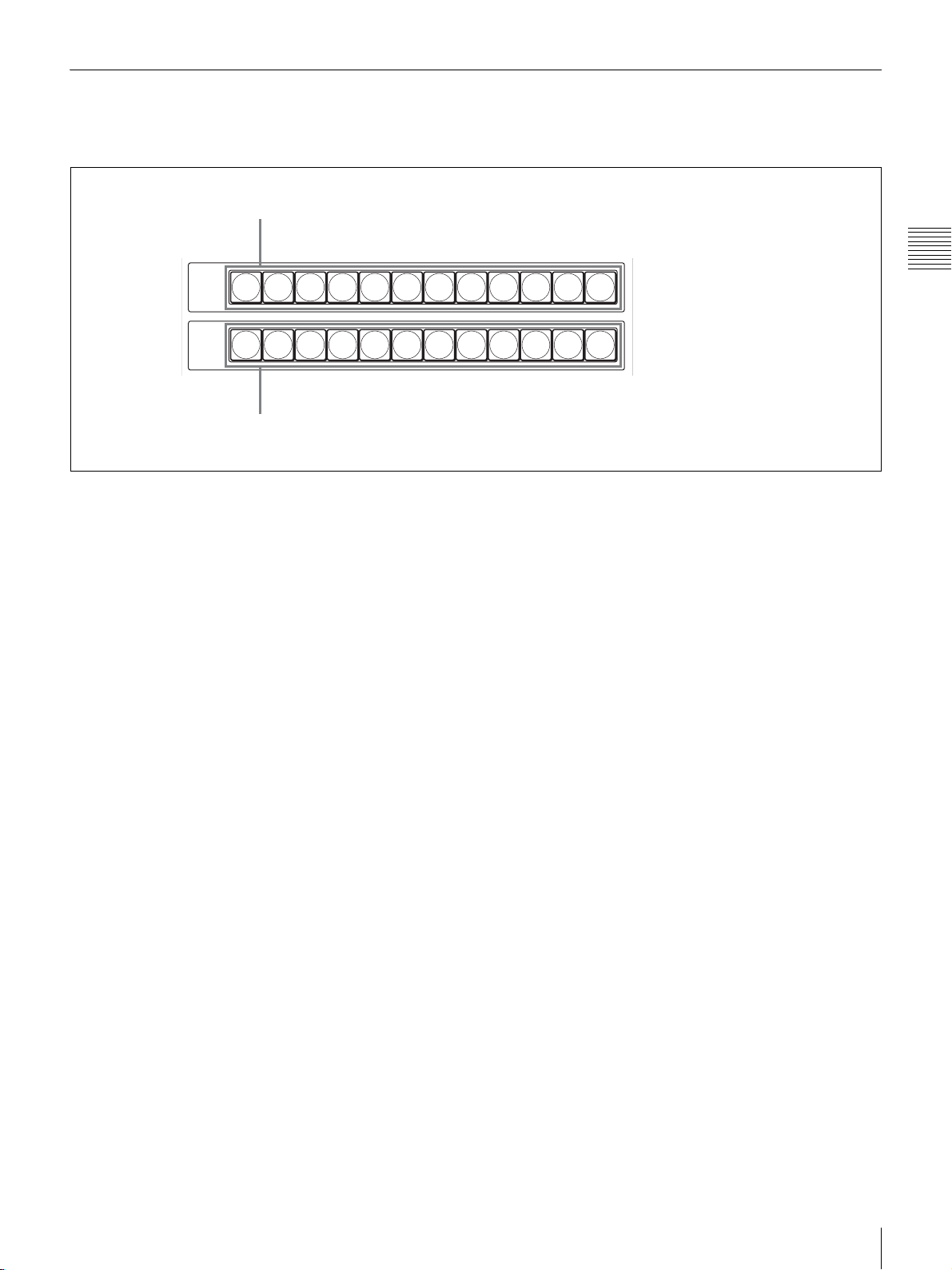
3 Cross-Point Bus Section
The cross-point bus section includes two types of crosspoint buttons, PGM select buttons and NEXT select
1 PGM select buttons
PGM
1
23456789101112
NEXT
123456789101112
2 NEXT select buttons
a PGM (program) select buttons
The signal output from the PGM connector is called PGM
(program) output video. Use these buttons to select a
background image of the program output video.
Pressing one of PGM select buttons 1 to 12 allows you to
select the video (input video, color matte, color bars, or
frame memory video) assigned to the selected button.
buttons. This section functions for modes other than SW
mode.
Chapter 2 Locations and Functions of Parts
b NEXT select buttons
Use these buttons to select a foreground image to be output
next to the present PGM output.
Pressing one of NEXT select buttons 1 to 12 allows you to
select the video (input video, color matte, color bars, or
frame memory video) assigned to the selected button.
For details on the cross-point buttons, see “Setting the Bus
Mode for the Cross-Point Buttons (Menu Page 943)” on
page 56.
Control Panel
19
Page 20

4 Effect Transition Section
The effect transition section is used for effect transition in
video switching. This section is used for modes other than
SW mode.
1 PIP AUTO button
Chapter 2 Locations and Functions of Parts
2 DSK AUTO button
3 REV button
4 N/R button
5 MIX button
6 WIPE button
7 AUTO TRANS button
8 CUT button
DSK
AUTO
N/R
MX
AUTO
TRANS
PIP
AUTO
REV
WIPE
CUT
9 Transition lever
q; Transition indicator
a PIP AUTO (automatic picture-in-picture) button
When you press this button, it lights in green, and the video
set in the PIP menu is inserted in the program output video
after automatic transition (PIP AUTO function).
When the PIP AUTO function is complete, the button turns
red. Pressing the button again cancels PIP and the button
turns green. After automatic transition, the PIP AUTO
button goes dark.
If you press this button while the PIP AUTO function is
being executed (the button lights in green), the function is
suspended and the button remains lit in green. Pressing the
button again restores the PIP AUTO function.
Lights in green Lights in red Lights in green
Press
Lights in green Remains lit in green Lights in green
Press PressPress
PIP
AUTO
PIP AUTO
starts
PIP
AUTO
PIP AUTO
starts
PIP
AUTO
PIP AUTO
completes
PIP
AUTO
PIP AUTO
suspended
Press
PIP
AUTO
PIP
canceled
PIP
AUTO
PIP AUTO
restarts
Note
Goes dark
PIP
AUTO
PIP erased
completely
You can set the transition time of the PIP AUTO function
in the menu (page 80).
b DSK AUTO (automatic downstream key) button
When you press this button, it lights in green, and the DSK
(downstream key) set in the DSK menu is inserted in the
program output video after automatic transition (DSK
AUTO function).
When the DSK AUTO function is complete, the button
turns red. Pressing the button again cancels DSK and the
button turns green. After automatic transition, the DSK
AUTO button goes dark.
If you press this button while the DSK AUTO function is
being executed (the button lights in green), the function is
suspended and the button remains lit in green. Pressing the
button again restores the DSK AUTO function.
Note
You can set the transition time of the DSK AUTO function
in the menu (page 80).
c REV (reverse) button
When you press to light up this button, a transition is
executed in the reverse direction. Pressing this button
again to make it go dark cancels reverse transition mode.
d N/R (Normal/Reverse) button
When you press to light up this button, each transition of
wipe is executed in normal or reverse direction
alternatively. When you press this button again to make it
go dark, transitions of wipe are executed in normal
direction only.
e MIX button
When you press to light up this button, the current video is
gradually switched to the next video while the two videos
20
Control Panel
Page 21
are overlapped during transition of the background video
(mix).
Note
h CUT button
When you press to light up this button, the present video is
instantaneously switched to the next program video during
transition of the background video (cut).
When wipe is selected, mix mode is canceled.
f WIPE button
When you press to light up this button, the current video
(background video) is gradually switched as if the next
video was wiping out the present video during transition of
the background video (wipe).
Note
When mix is selected, wipe mode is canceled.
g AUTO TRANS (automatic transition) button
When you press to light up this button, an effect is
automatically executed within the preset transition time
during transition of the background video (AUTO TRANS
function) (page 69).
When you press to light up this button while the AUTO
TRANS function is being executed (the button lights in
orange), the function is suspended (the button stays lit in
orange). Pressing the button again restores the AUTO
TRANS function, and the button goes dark when the
transition is complete.
i Transition lever
Use this lever to execute a transition of the background
video manually.
Note
Chapter 2 Locations and Functions of Parts
If the switcher is turned on when the transition lever is not
positioned at either end, move the lever back and forth
between both ends once. This action enables the function
of the lever.
j Transition indicator
The indicator shows the available direction of the
transition lever.
Moving the transition lever in the direction of the indicator
lit starts a transition.
Note
If you press the AUTO TRANS button after moving the
transition lever to the middle, for example, an
inconsistency between the application of the effect and the
position of the transition may occur. In such a case, both
indicators may light up.
Do not use excessive force while operating the transition
lever.
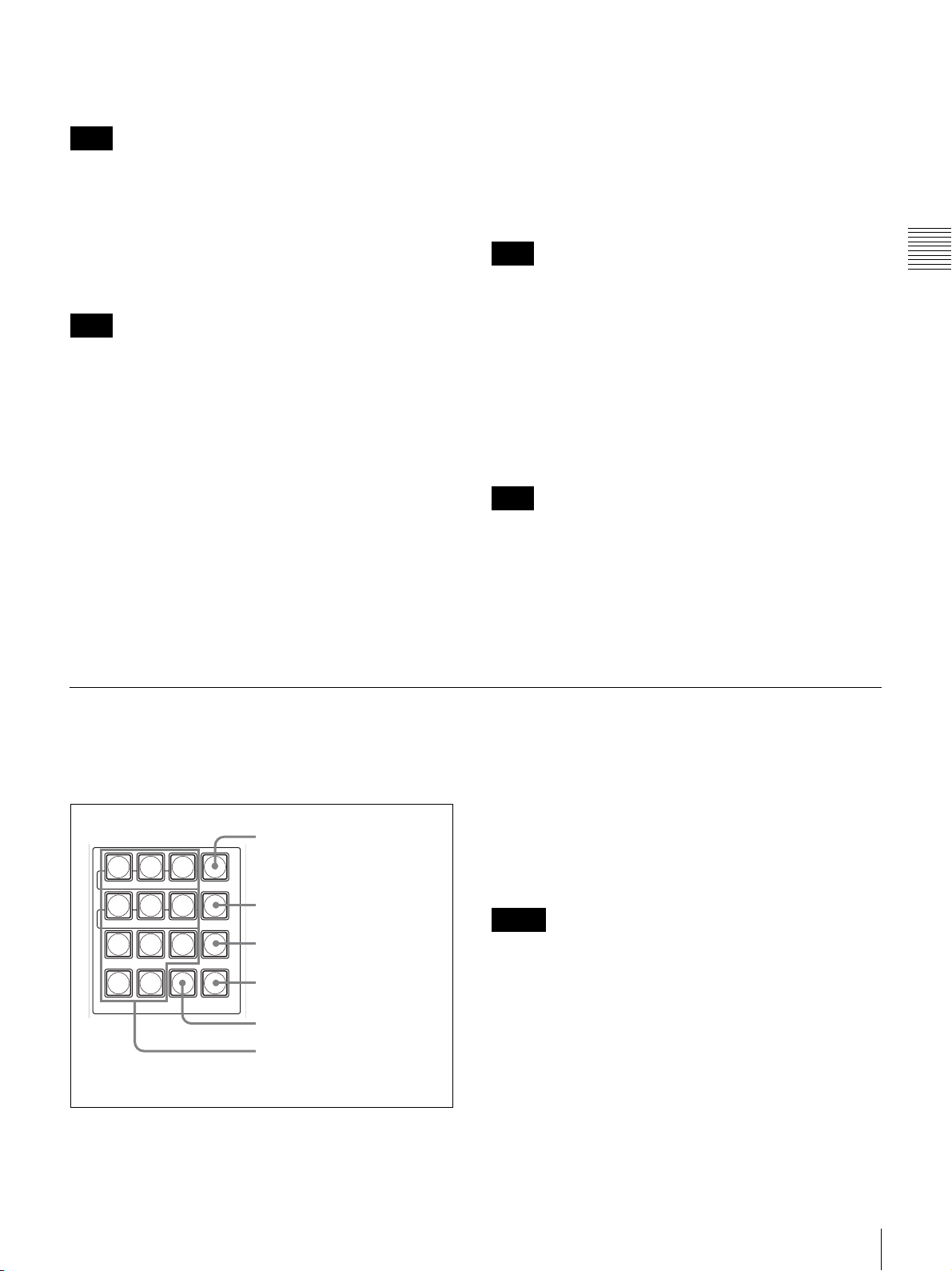
5 Menu/Snapshot/Camera Position Section
The buttons in the menu/snapshot/camera position section
differ in function depending on whether the switcher is in
menu mode, SW mode, or CAM mode.
1 MENU button
7
89
DSK PIP SETUP
456
MEM
WIPE MATT
123
0.
MENU/SNAP
SHOT/CAMERA POSITION
MENU
DIRECT
RECALL
PRESET
CLEAR RECALL
2 DIRECT RECALL button
3 PRESET button
4 RECALL button
5 CLEAR button
6 Numeric (0 to 9) buttons and .
(dot) button
a MENU button
When you press to light up this button, the display panel is
set to menu mode.
In menu mode, pressing one of numeric buttons 4 to 9
allows you to display one of the top menus (see “Top menu
list”). The selected numeric button lights up. To return to
CAM or SW mode, press the MENU button or press the
CAM or SW mode button.
Notes
• When you switch to menu mode, the menu page
displayed last will be shown on the display panel. At the
time of the system startup the display panel shows the
top page of the SETUP menu.
• For the procedures for menu operation, see “To display
the menu” on page 22.
• For details on the setting menus, see “Menu List” on
page 131.
Control Panel
21
Page 22
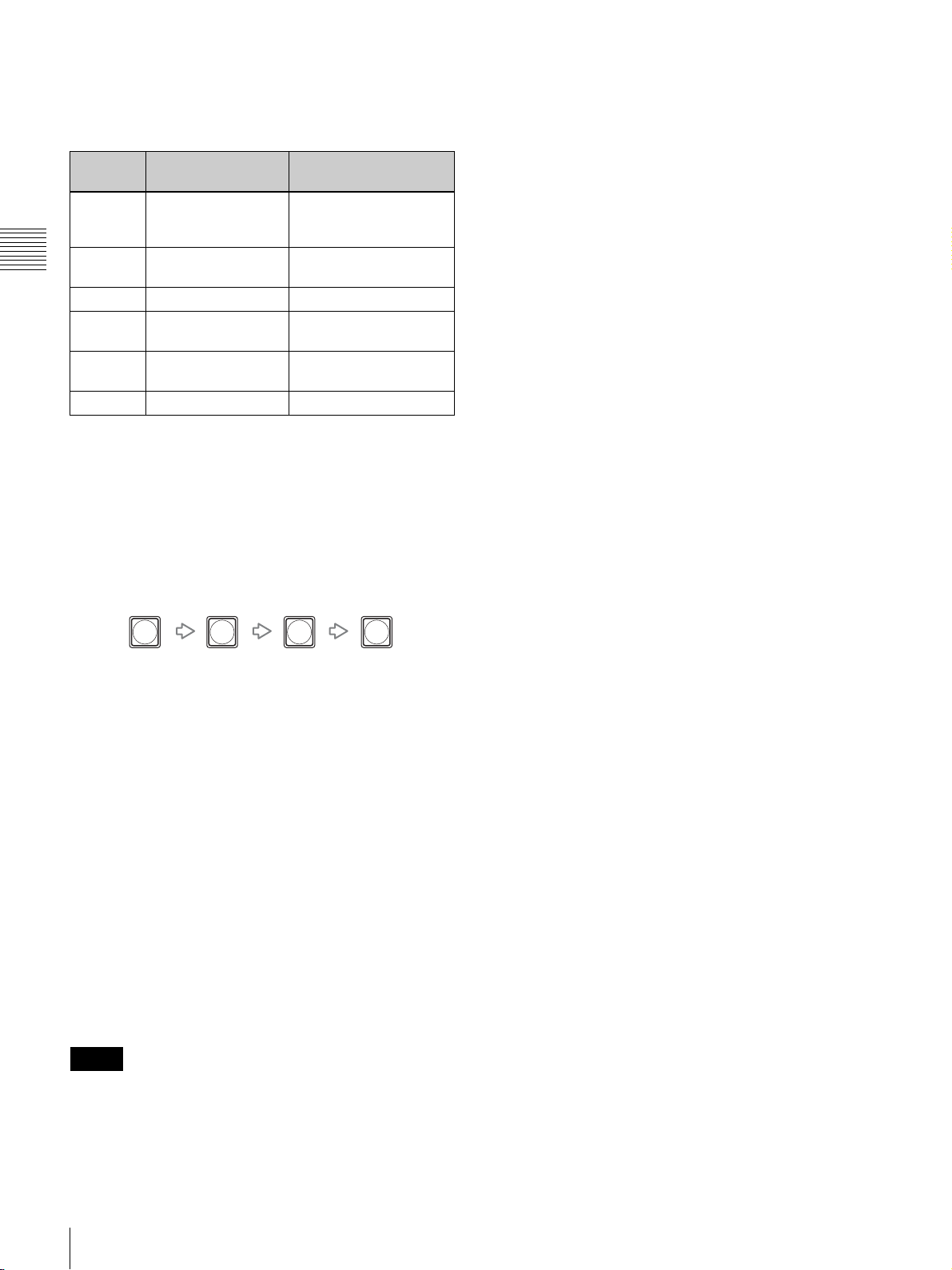
Top menu list
Pressing one of numeric buttons 4 to 9 displays the top
menu listed below. The corresponding button lights up.
Numeric
button
4MEM (memory)
5 WIPE menu Setting the wipe pattern
Chapter 2 Locations and Functions of Parts
6 MATT menu Setting the color matte
7 DSK menu Setting the DSK
8 PIP menu Setting the PIP (picture-
9 SETUP menu Setting up the system
Top menu Menu description
menu
Importing an image into
the frame memory, Time
stamp setting for a file
or border
(downstream key)
in-picture)
To display the menu
A three-digit menu page is assigned to each of all the
setting menus displayed in menu mode.
• To recall camera position number or snapshot number 10
or larger, cancel direct recall mode and use the RECALL
button to recall it.
• If you set the tenths digit (Bank) of the snapshot number
in the menu, you can recall the two-digit snapshot
number only by pressing one of numeric buttons 0 to 9
that corresponds to the ones digit of the snapshot number
(page 139).
c PRESET button
Use this button to store a setting in a camera position
number, snapshot number, direct wipe number, or direct
PIP number.
x When CAM mode is selected
You can store the pan, tilt or zoom position or other camera
settings in the camera position numbers. Up to 99 settings
can be stored in the 1 to 99 positions for each VISCA
camera.
1Use one of numeric buttons 0 to 9 to display the flashing
position number in which you wish to store the setting
on the display panel.
2Hold the PRESET button pressed.
To specify the menu page directly, press the numeric
buttons for “third-digit number,” “. (dot),” “second-digit
number,” and “first-digit number” in sequence.
Example: To specify menu page 912
9.12
b DIRECT RECALL button
When you press to light up this button, the switcher is set
to direct recall mode, and you can recall the preset settings
stored for numeric buttons 0 to 9. Pressing the DIRECT
RECALL button again releases direct recall mode.
In direct recall mode you can operate the following:
x When CAM mode is selected
The preset setting stored for the camera position numbers
1 to 9 can be recalled by pressing numeric buttons 1 to 9.
x When SW mode is selected
The preset setting stored in the snapshot numbers, direct
wipe numbers, or direct PIP numbers 0 to 9 on the switcher
can be recalled by pressing numeric buttons 0 to 9.
For details on snapshot numbers, direct wipe numbers and
direct PIP numbers, see “Storing the Settings of a Wipe,
PIP, and Setting Menu Items” on page 97.
Notes
• When the DIRECT RECALL button is pressed while the
MENU button is lit, menu mode is canceled, and the
switcher enters CAM or SW mode.
For details, see “Storing the Camera Settings” on page
111.
x When SW mode is selected
You can store the various switcher settings. Up to 100
settings can be stored in the 0 to 99 snapshot numbers, and
up to 10 settings can be stored in the 0 to 9 direct wipe or
direct PIP numbers.
1Use one of numeric buttons 0 to 9 to display a flashing
snapshot, direct wipe or direct PIP number in which you
wish to store the setting on the display panel.
2Hold the PRESET button pressed.
For details, see “Storing the Settings of a Wipe, PIP, and
Setting Menu Items” on page 97.
d RECALL button
Press this button to recall the setting stored in the camera
position number on the camera or in the snapshot, direct
wipe, or direct PIP number on the switcher.
x When CAM mode is selected
You can recall the pan, tilt or zoom position or other
camera settings stored in camera position numbers 1 to 99.
1Use one of numeric buttons 0 to 9 to display the flashing
position number to be recalled on the display panel.
2Press the RECALL button.
x When SW mode is selected
You can recall the various preset switcher settings.
1Use one of the numeric buttons 0 to 9 to display the
flashing snapshot, direct wipe or direct PIP number to
be recalled on the display panel.
2Press the RECALL button.
22
Control Panel
Page 23
e CLEAR button
For procedures for menu page input, see “To display the
menu” on page 22.
x When menu mode is selected
When this button is pressed, the last two digits of the menu
page reset to “00.”
x When CAM mode is selected
Use numeric buttons 0 to 9 to enter the camera position
number.
x When CAM mode is selected
When this button is pressed, the camera position number
displayed on the display panel disappears.
x When SW mode is selected
Use numeric buttons 0 to 9 to enter the snapshot, direct
wipe, or direct PIP number.
x When SW mode is selected
When this button is pressed, the snapshot, direct wipe, or
direct PIP number displayed on the display panel
disappears.
Note
To enter the two-digit number, press the second-digit
number then the first-digit number.
f Numeric buttons 0 to 9 and . (dot) button
x When menu mode is selected
To correct a number entered, press the CLEAR button then
enter the correct number.
Use the numeric buttons and . (dot) button to enter menu
page.
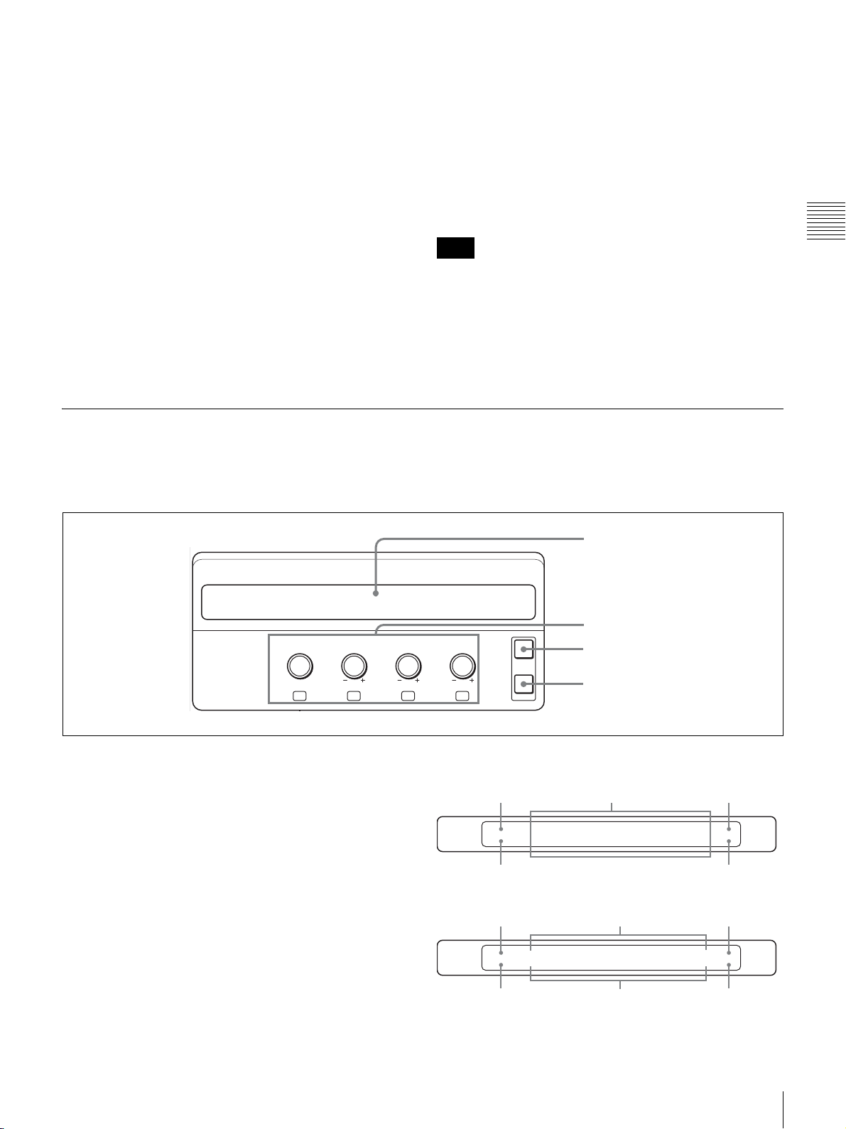
6 Display Panel / Camera/Switcher/Menu Control Section
The buttons and controls in this section differ in function
depending on whether the switcher is in CAM mode, in
SW mode or in menu mode.
Chapter 2 Locations and Functions of Parts
FOCUS BRIGHT ZOOM PAN/TILT
NEAR FAR
F1 F2 F3 F4
a Display panel
Displays the menu, the current effect, and the camera
settings.
While viewing the display panel, you can check and
change the settings.
When the menu of a lower layer has further lower layers,
the menu name is followed by “..”
The following display panel shows a representative
example:
1 Display panel
2 Adjustment controls
EXIT
PAG E
3 EXIT button
4 PAGE button
Menu layers in menu mode
Higher menu layer
SETUP
INPUT
Current displayed menu layer
Higher menu layer Setting items Page number
NAME..
FS..
Lower menu layer Page number
ASSIGH..
SIDE..
ADJUST.. 1/1
PROC..
920
Menu page
INPUT
ADJUST
Current displayed
menu layer
XPT BTN3 Y-LEVEL
1.00
SETUP
0.0
C-LEVEL
1.00
3/6
923
Menu pageSetting values
Control Panel
23
Page 24

Setting status in SW mode
Switcher mode Setting items
x When SW mode is selected
You can use the adjustment controls for the following
operations and adjustments:
SW MODE
SNAP:80
Snapshot number Setting values
MV TYPE4 XPT HOLD
On
ME AUTO
30
Setting status in CAM mode
Chapter 2 Locations and Functions of Parts
Input signal Setting items
SIG:CAM1
POS:12
Camera position number Setting values
FOCUS
MANUAL
SPEED
1/1000
CONSTANT
1/8
CONSTANT
15/24
b Adjustment controls (F1/FOCUS, F2/BRIGHT,
F3/ZOOM, F4/PAN/TILT)
The function of the controls differ among menu mode,
CAM mode and SW mode.
x When menu mode is selected
You can change the setting of four groups of each menu
display, using the F1 to F4 controls located below each
menu display.
To move to a lower layer
There are lower layers when the menu name is followed by
“..”
Turn the adjustment control (F1 to F4) located below the
menu name you with to operate to highlight it then press
the corresponding adjustment control. The display
switches to the next lower layer of the menu.
To change a setting item
When the setting item can be changed, press the
corresponding adjustment control (F1 to F4) to display
another setting item.
F1 control
You can select the type of multi-viewer.
F2 control
You can select whether to reflect the setting registered for
the snapshot number for the assigned select button in the
cross-point bus section, DSK source, or PIP source when
that setting is recalled.
Press the F2 control to select “XPT HOLD,” “DSK
HOLD” or “PIP HOLD” then turn the F2 control to set the
selected item to “On” or “Off.” When set to “On,” the
setting registered for the snapshot number is not reflected.
F3 control
You can select a wipe pattern or direct select mode.
Pressing the F3 control displays a wipe pattern or
“DIRECT” on the display panel.
If you turn the F3 control while a wipe pattern is displayed,
you can change the wipe pattern.
If you turn the F3 control while “DIRECT” is displayed,
you can select a snapshot number (“SS”), direct wipe
(“Wipe”), or direct PIP (“PIP”), in sequence. After
selecting direct select mode, enter the register number with
numeric buttons 0 to 9 then press the RECALL button. The
setting of a snapshot, direct wipe, or direct PIP stored in
the selected register number is recalled.
F4 control
You can change the transition time in units of frames for
executing a transition by pressing the AUTO TRANS
button.
Press the F4 control to select “ME AUTO,” “DSK
AUTO,” or “PIP AUTO” then turn the F4 control to
change the value.
To change the transition time for a mix or wipe effect,
select “ME AUTO.” For DSK AUTO select “DSK
AUTO,” and for PIP AUTO select “PIP AUTO.”
To change a setting value
Turn the corresponding adjustment control (F1 to F4) to
change the setting value. To enable the settings that have
been changed, executing “Exec” may be required.
Notes
• The default setting can be obtained by holding the
corresponding adjustment control (F1 to F4) pressed if
the default setting is preset at the factory.
Depending on the setting items, turning the control while
holding it pressed enables the setting value to change
roughly.
• You can display a lower layer of the menu by specifying
the three-digit menu page with numeric buttons 0 to 9
and the . (dot) button in the menu/snapshot/camera
position section.
24
Control Panel
x When CAM mode is selected
You can set or adjust the following using the F1 to F4
adjustment controls:
FOCUS control
You can adjust the focus manually when the AUTO/
MANUAL button in the CAMERA/DSK/AUX bus
section is not lit (manual focus mode) and “MANUAL” or
“ASSIST” is displayed under “FOCUS.”
BRIGHT (brightness) control
You can adjust the brightness when the exposure mode is
set to SHUTTER Pri, IRIS Pri, GAIN Pri, or MANUAL on
the camera. You can also adjust the exposure
compensation level when EX-COMP (exposure
compensation) is set to ON on the camera.
Page 25

ZOOM control
You can change the zoom speed when you operate the
zoom by using the dial on the upper part of the joystick.
Press the control to switch between “CONSTANT” and
“VARIABLE.” Turn the control to select the speed from
among 1/8 to 8/8.
PAN/TILT (panning/tilting) control
You can change the panning and tilting speed when you
operate panning/tilting by using the joystick.
Press the control to switch between “CONSTANT” and
“VARIABLE.” Turn the control to select the speed from
among 1/24 to 24/24.
Note
You can select the speed from among 0.5/24 to 24/24 for
the BRC-Z700 camera.
c EXIT button
When menu mode is selected, press this button to return to
the next higher layer of the menu. The last digit of menu
page changes to “0” and flashes. You can enter the last
digit of that number using numeric buttons 0 to 9.
When you press this button while the last digit of the menu
page is flashing or the last digit is “0,” the last two digits
reset to “00.”
Chapter 2 Locations and Functions of Parts
Note
When “TOP” is shown at the lower left of the display
panel, the top menu is displayed. In this case, pressing the
EXIT button does not change the display.
d PAGE button
The number of pages for the displayed menu and the
individual menu page number are displayed at the right
end of the display panel. The number of pages indicates
how many pages in the same layer the displayed menu has.
When you press the PAGE button, the display changes to
the next menu page. When the button is pressed while the
last page is displayed, the first page is restored.
Control Panel
25
Page 26

7 Camera Menu/Location Control Section
The buttons in this section differ in function depending on
whether the switcher is in CAM or SW mode.
Chapter 2 Locations and Functions of Parts
x Functions in CAM mode
a CAMERA MENU button
When you hold this button pressed to light up the button,
the main menu of the camera is displayed on the image
shot by the camera selected with one of the CAMERA
buttons in the CAMERA/DSK/AUX bus section. Hold the
button pressed again to turn off the main menu.
If the selected camera has two or more main pages, each
press of the button switches the main menu to the next
page. After the last page is displayed, the main menu of the
camera disappears.
Holding the CAMERA MENU button pressed while any
setting menu of the camera is displayed restores the main
menu.
CAMERA
MENU
LEFTXENTER
DOWN
CENTER
FINE
The functions of the buttons are explained for both modes
individually.
1 CAMERA MENU button
UP
RIGHT
Y
CAM
2 Camera menu operation buttons/
Z
location control buttons
• To restore the main menu, hold the CAMERA MENU
button pressed.
Note
The camera menu operation buttons in this section
function the same as the V/v/B/b/HOME buttons on the
Remote Commander supplied with the camera. For details,
refer to the Operating Instructions supplied with the
camera.
x Functions in SW mode
a CAMERA MENU button
This button cannot be used in SW mode.
Note
If the DATA MIX switch on the BRC-H700, BRC-Z700 or
BRC-Z330 camera is set to OFF, or the DATA MIX
switch on the BRU-H700 HD Optical Multiplex Unit is set
to OFF, the menu of the camera is not displayed on the
output image from the interface board installed in the
camera or the BRU-H700. For details, refer to the
Operating Instructions supplied with the camera or the
BRU-H700.
b Camera menu operation buttons (UP/DOWN/
LEFT/RIGHT/ENTER)
Use these buttons to operate the menu on the camera when
the menu is displayed on the image shot by the camera
selected with one of the CAMERA button in the
CAMERA/DSK/AUX bus section.
• Select the menu item from the main menu with the UP or
DOWN button then press the ENTER button to display
the selected setting menu.
• Select the setting item to be changed with the UP or
DOWN button then press the LEFT or RIGHT button to
change the setting value.
b Location control buttons (FINE/CENTER/X/Y/Z)
Use these buttons to set the function of the joystick when
it is to be used in menu mode.
FINE button
Pressing to light up this button reduces the speed of setting
using the joystick. This enables you to make fine
adjustment. To restore the normal setting speed, press the
button again to make it go dark.
CENTER button
Pressing this button resets the setting data obtained using
the joystick to the factory preset settings.
X, Y and Z buttons
Pressing to light up one of these buttons enables the
following operation of the joystick:
X: to move the joystick horizontally
Y: to move the joystick vertically
Z: to turn the dial on the upper part of the joystick
Press one of these buttons again to make it go dark to
disable the corresponding operation.
26
Control Panel
Page 27

Note
Note that the joystick does not function if the X, Y and Z
buttons are all unlit.
8 Joystick
The functions of the joystick differ depending on whether
the switcher is in CAM or SW mode.
The functions of the joystick are explained for both modes
individually.
Joystick
x Functions in CAM mode
Use the joystick for panning, tilting and zooming
operations of the camera selected with the CAMERA
button in the CAMERA/DSK/AUX bus section.
When you incline the joystick left or right, the camera
pans. When you incline it forward or backward, the camera
tilts. The pan/tilt speed changes according to the angle of
the inclination.
When you turn the dial on the upper part of the joystick
clockwise, the subject becomes larger (zoom in). When
you turn it counterclockwise, the subject becomes smaller
(zoom out).
Chapter 2 Locations and Functions of Parts
Notes
• Using the menu, you can change the pan/tilt direction
and speed when you operate the joystick to pan or tilt the
camera (page 109).
• Using the menu, you can change the zoom magnification
or zoom speed when you operate the dial on the upper
part of the joystick to zoom in/out (page 108).
x Functions in SW mode
In menu mode, the joystick can be used to set the display
location and size of a PIP image, and luminance, saturation
and hue of color matte signals or chroma keys.
For detailed operations, see “To adjust the size and
display position of an embedded video using the joystick”
on page 77 and “To specify the chroma key automatically
using the joystick” on page 92.
Control Panel
27
Page 28

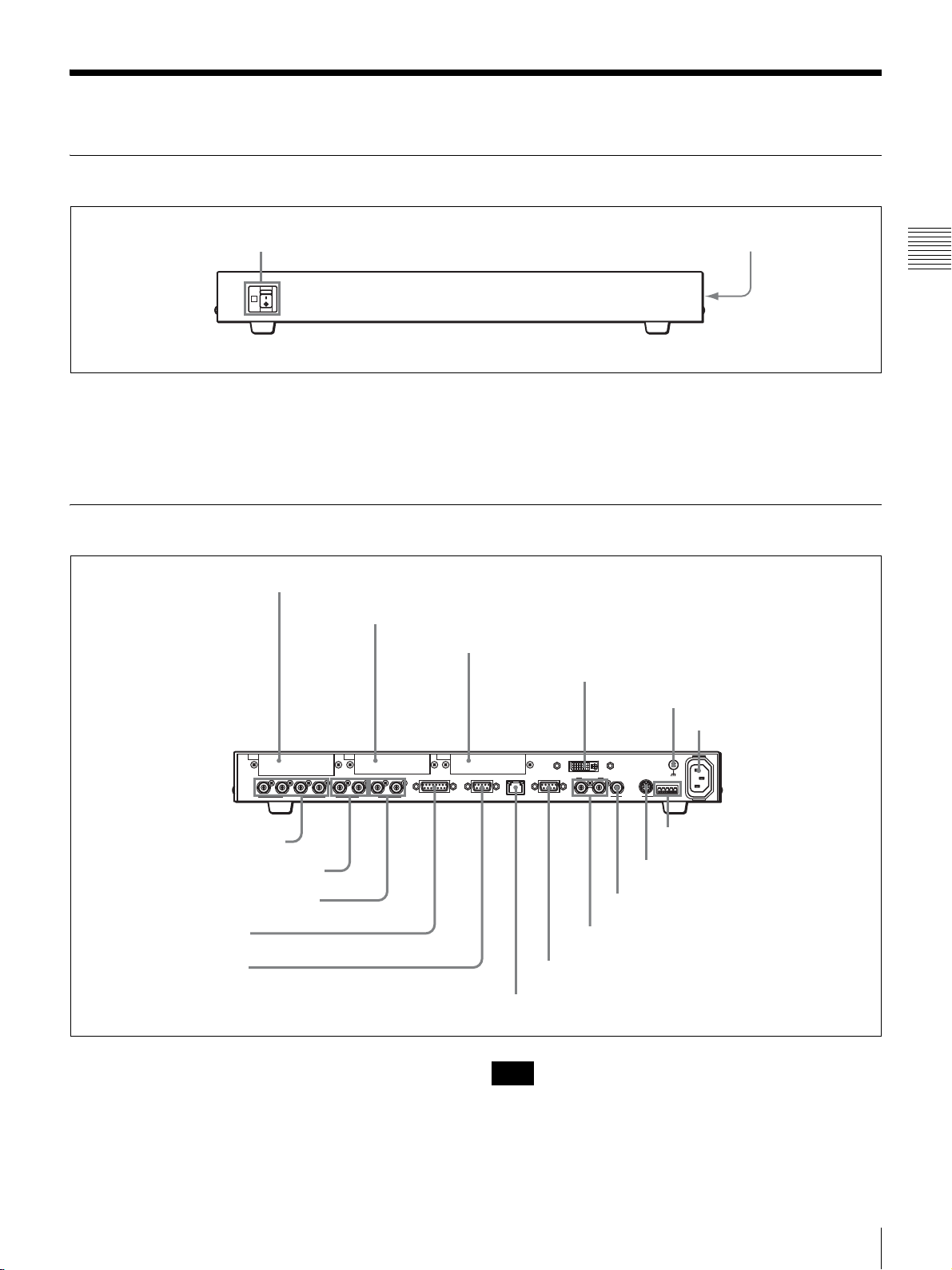
9 Rear Panel Section
Chapter 2 Locations and Functions of Parts
1 PROCESSOR connector
2 DC IN 12V connector
3 Power switch
PROCESSOR
5 Bit switches
4 Attachment hole for antitheft wire
a PROCESSOR connector
Connect to the PANEL connector on the Processor Unit
with the supplied control cable.
b DC IN 12V connector
Connect the supplied AC power adaptor.
c Power switch
Turns the Control Panel ON/OFF.
d Attachment hole for antitheft wire
This is a hole (3 mm × 7 mm) for attaching a commercially
available antitheft wire.
e Bit switches
Used for future system expansion. All the switches are set
to the OFF (upper) positions at the factory. Do not change
these settings.
DC IN 12V
ON
OFF
28
Control Panel
Page 29
Processor Unit
Front Panel
1 POWER switch and indicator
ON
OFF
POWER
a POWER switch and indicator
Turns the Processor Unit ON/OFF. Press the ? side of the
switch to turn it on. The indicator lights up in green.
Rear Panel
1 IN1 card slot
2 IN2 card slot
2 Rack mounting attachment screws
Chapter 2 Locations and Functions of Parts
b Rack mounting attachment screws
Use these screws to attach the supplied rack mount
brackets for installing the switcher in a rack. Four screws
each on the right and left sides are attached at the factory.
3 OUT card slot
4 DVI-I OUT connector
5 U (ground) terminal
6 ~ AC IN connector
IN1
1
234PGM1 PGM2 AUX1
IN2 OUT
GPI I/O PANEL LAN(10/100) REMOTE
AUX2 REF IN REF OUT
SDI OUTSDI IN
7 SDI IN 1 to 4 connectors
8 PGM1/PGM2 output connectors
9 AUX1/AUX2 output connectors
q; GPI I/O connector
qa PANEL connector
a IN1 (input 1) card slot
Insert the BRSA-20HSD1 or BRSA-20DD1 interface
board (not supplied).
b IN2 (input 2) card slot
Insert the BRSA-20DD1 interface board (not supplied).
RS-232C
~AC IN
RS-422
DVI-I OUT
GENLOCK VISCA
qj RS-422 connector
qh RS-232C connector
qg REF OUT connector
qf REF IN connector
qd REMOTE connector
qs LAN (10/100) connector
Note
The optional BRSA-20HSD1 interface board cannot be
installed in the IN2 card slot.
Processor Unit
29
Page 30

c OUT (output) card slot
Insert the BRSA-20DD2 interface board (not supplied).
d DVI-I OUT (DVI-I output) connector
Connect to the DVI input connector on a monitor.
Note
Be careful not to use the wrong connector as the
qa PANEL connector and qd REMOTE connector are the
same connector type.
e U (ground) terminal
Used to connect to a ground lead.
Connect a ground lead when you use this switcher.
f ~ AC IN connector
Chapter 2 Locations and Functions of Parts
Connect to an AC outlet with the supplied power cord.
g SDI IN (SDI input) 1 to 4 connectors (BNC type)
Input an SDI signal from a video camera or VCR (player).
You can input the SDI signal from 1 to 4 connectors. The
built-in frame synchronizer enables input of asynchronous
signals.
Note
The switcher cannot accept SD-SDI and HD-SDI signals
simultaneously. Select SD-SDI or HD-SDI signal using
the menu.
h PGM1 (program 1)/PGM2 (program 2) output
connectors (BNC type)
Connect to the SDI input connector on a monitor. The
program video with an effect applied is output via these
connectors. The same signal is output through the PGM1
and PGM2 connectors.
i AUX1 (auxiliary 1)/AUX2 (auxiliary 2) output
connectors (BNC type)
Connect to the SDI input connector on a monitor. The
PGM (program), PVW (preview) or MV (multi-viewer)
video signal, or any of the input signals selected with 1 to
12 buttons in the cross-point bus section can be output via
these connectors. The AUX1 and AUX2 output connectors
are able to output different signals.
l LAN (10/100) connector
Connect to a computer with a cross-type LAN cable (not
supplied). You can store the setting data for the switcher in
the connected computer and import the data from the
computer.
CAUTION
For safety, do not connect the connector for peripheral
device wiring that might have excessive voltage to this
port. Follow the instructions for this port.
CAUTION
When you connect the LAN cable of the unit to peripheral
device, use a shielded-type cable to prevent malfunction
due to radiation noise.
m REMOTE connector (D-sub 9-pin)
This connector is used for system expansion.
n REF IN (reference sync input) connectors (BNC
type)
A reference synchronization signal is input via this
connector from an external device. The other REF IN
connector is used as a loop-through output connector. If it
is not to be used as a loop-through output, attach a 75-ohm
terminator to this connector.
o REF OUT (reference sync output) connector (BNC
type)
If a reference synchronization signal is not input via the
REF IN connector, the built-in reference synchronization
signal is output through this connector.
j GPI I/O (GPI
*
input/output) connector (D-sub 15-
pin)
Connect to the tally connector on the video camera to
enable the tally lamp on the camera to light up. With the
switcher connected via this connector to an external
device, you can control the PGM or NEXT select buttons
on the switcher from the connected device.
* General-Purpose Interface
k PANEL (control panel) connector (D-sub 9-pin)
Connect to the PROCESSOR connector on the Control
Panel with the supplied control cable.
30
Processor Unit
p RS-232C connector (mini-DIN 8-pin)
Connect to the VISCA RS-232C connector on a camera.
q RS-422 connector (Connector plug)
Connect to the VISCA RS-422 connector on a camera
using the supplied RS-422 connector plug (5-pin).
For connection using the RS-422 connector plug, see “To
Use the VISCA RS-422 Connector Plug” on page 151.
Note
For VISCA connection, be sure to use either connection
using the RS-422 or the RS-232C connector.
Page 31

BRSA-20HSD1 HD/SD-SDI Input
BRSA-20DD2 DVI Output Board (Not
Board (Not Supplied)
SDI IN 5 to 8 connectors
5678
SDI IN
SDI IN (SDI input) 5 to 8 connectors
Input SDI signals from a video camera or a VCR (player).
The switcher can accept up to eight SDI inputs using the
four inputs (SDI IN 5 to 8) on this board and the SDI IN 1
to 4 connectors on the Processor Unit.
The built-in frame synchronizer enables input of
asynchronous signals.
BRSA-20DD1 DVI Input Board (Not Supplied)
Supplied)
DVI-I OUT connector
DVI-I OUT
Chapter 2 Locations and Functions of Parts
DVI-I OUT (DVI-I output) connector
Connect to the DVI input on a monitor.
Up to two monitors can be used, using this connector and
the DVI-I OUT connector on the Processor Unit.
The connector complies with the DVI-I standards and is
able to handle both digital RGB and analog RGB signals.
Note
When “RESO” is set to “HD 50” or “HD 59.94” on menu
page 932, only analog component signals are output
through this connector.
DVI-I IN connector
DVI-I IN
DVI-I IN (DVI-I input) connector
Inputs a DVI signal from a computer.
Using this connector enables the switcher to handle an
RGB signal input from a computer.
The connector complies with the DVI-I standards and is
able to handle both digital RGB and analog RGB signals.
Processor Unit
31
Page 32

Chapter 2 Locations and Functions of Parts
32
Processor Unit
Page 33

Preparations
Chapter
3
Connecting External Equipment
This chapter describes connections with peripheral devices.
Connect the peripheral devices, connect and install the switcher, then perform
the basic setup of the switcher using the menus.
Chapter 3 Preparations
Connecting External Equipment
33
Page 34

Connecting VISCA Cameras
Up to seven Sony BRC-series VISCA-compatible cameras can be connected to
the switcher.
BRSA-20HSD1 HD/SD-SDI input board
(not supplied)
5678
IN1 IN2 OUT
SDI IN
1234PGM1 PGM2 AUX1
SDI OUTSDI IN
GPI I/O PANEL LAN(10/100) REMOTE
AUX2 REF IN REF OUT
GENLOCK VISCA
DVI-I OUT
RS-232C
~
AC IN
RS-422
to SDI IN 1 to 4
VISCA RS-422
connector plug
Chapter 3 Preparations
(supplied)
VISCA RS-422 connecting
First camera
cable
(See page 150.)
to VISCA RS-422
R
OFF ON
IR SELECT
1 2 3 4 5 6 7 8 9
1 2 3
DATA MIX
OFF ON
VISCA RS-422
75
RGB/COMPONENT
DC IN 12V
IN VISCA RS-232C OUT
EXT SYNC IN
S VIDEO
HD/SD-SDI
VIDEO
to AC power adaptor
output card
to VISCA RS-422
to SDI OUTPUT
VISCA RS-422 connecting cable
to VISCA RS-422
Second camera
to SDI OUTPUT
Third camera
to SDI OUTPUT
IN VISCA RS-232C OUT
IN VISCA RS-232C OUT
1 2 3 4 5 6 7 8 9
1 2 3 4 5 6 7 8 9
VISCA RS-422
R
IR SELECT
OFF ON
1 2 3
DATA MIX
OFF ON
VISCA RS-422
75
RGB/COMPONENT
DC IN 12V
EXT SYNC IN
S VIDEO
VIDEO
to AC power adaptor
to VISCA RS-422
VISCA RS-422 connecting cable
to VISCA RS-422
R
IR SELECT
OFF ON
1 2 3
DATA MIX
OFF ON
75
RGB/COMPONENT
DC IN 12V
EXT SYNC IN
S VIDEO
VIDEO
to AC power adaptor
34
Connecting External Equipment
Page 35

To connect the video cable
Connect the SDI outputs on cameras to the SDI IN 1 to 4 connectors on the
switcher.
Notes
• To output an SDI video signal from a BRC-series camera, installing the
interface board that enables output of a SDI signal in the camera is required.
For details, refer to the Operating Instructions supplied with the camera.
• Installing the optional BRSA-20HSD1 HD/SD-SDI input board enables
connection of up to seven BRC-series cameras.
• When the switcher handles SDI signals, either an SD-SDI or HD-SDI signal
must be used. Both signals cannot be handled at the same time.
To connect the VISCA control cable
Connect the RS-422 or RS-232C connectors on BRC-series cameras controlled
by the switcher via the RS-422 or RS-232C connectors on the switcher. Up to
seven BRC-series cameras can be connected in daisy-chain connection. For
details on daisy-chain connection, refer to the Operating Instructions supplied
with the cameras.
To connect the camera to the switcher via the RS-422 connector on the switcher,
prepare the connecting cable using the RS-422 connector plugs supplied with
the switcher and camera.
For preparing the connecting cable, see the pin assignments of the VISCA RS422 connector (page 148) and “Wiring Example of VISCA RS-422 Connection”
(page 150).
For use of the VISCA RS-422 connector plug, see “To Use the VISCA RS-422
Connector Plug” on page 151.
To configure the cameras
Set the following setup items for all the connected BRC-series cameras to the
same values.
HD/SD select switch SD-SDI or HD-SDI
Camera address selector 0 (Normally, automatically assigned)
Video format 59.94i or 50i
VISCA communication mode RS-422 or RS-232C
Communication baud rate 9600 bps or 38400 bps
Chapter 3 Preparations
To connect the cameras to the AC power supply
After the cameras are connected to the switcher, connect the AC power adaptors
supplied with the cameras to AC outlets.
The cameras turn on, pan and tilt automatically, and move to the position stored
as camera position 1.
Connecting External Equipment
35
Page 36

Connecting a Video Output Device Such as a Camera Other Than a BRCSeries Camera
Connect a camera or video output device equipped with an SDI output to the
SDI IN connector on the switcher.
Chapter 3 Preparations
Connecting a DVI Signal Output Device
To use an image output from the DVI output on a computer, install the optional
BRSA-20DD1 DVI input board in the IN1 or IN2 card slot on the switcher to
connect to the computer.
5678
IN1 IN2 OUT
SDI IN
1234PGM1 PGM2 AUX1
CONPOSITE Y/C
ANALOG IN
GPI I/O PANEL LAN(10/100) REMOTE
AUX2 REF IN REF OUT
SDI OUTSDI IN
SDI IN 1 to 4
5678
IN1 IN2 OUT
SDI IN
1234PGM1 PGM2 AUX1
DVI-I IN
GPI I/O PANEL LAN(10/100) REMOTE
AUX2 REF IN REF OUT
SDI OUTSDI IN
~
RS-232C
AC IN
RS-422
DVI-I OUT
GENLOCK VISCA
D
L
O
H
L
s
J
S
/
l
G
j
W
T
B
A
Camera, etc. equipped with
an SDI output
BRSA-20DD1 DVI input board (not supplied)
~
RS-232C
AC IN
RS-422
DVI-I OUT
GENLOCK VISCA
DVI-I IN
Computer
Notes
• To connect a computer that supports an analog RGB output signal only, use a
commercially available conversion cable (D-sub 15-pin y analog DVI).
• The video signal format to be used can be set to “HD” or “SD” under
“FORMAT” on menu page 951 (page 50). When it is set to “SD,” small
characters and fine graphics output from a computer may be blurred.
36
Connecting External Equipment
Page 37

Connecting Monitors to the PGM1 And PGM2 Connectors
Program videos are output from the PGM1 and PGM2 connectors. These two
connectors output the same signal. Connect the PGM1 and PGM2 connectors
on the switcher to the SDI inputs on a monitor or VCR.
5678
IN1 IN2 OUT
SDI IN
1234PGM1 PGM2 AUX1
PGM1
+
–
+
–
+
–
+
–
+
–
+
–
Monitor, etc. equipped
with an HD-SDI input
SDI OUTSDI IN
GPI I/O PANEL LAN(10/100) REMOTE
AUX2 REF IN REF OUT
PGM2
VCR, etc. equipped
with an HD-SDI input
Connecting Monitors to the AUX1 And AUX2 Connectors
One signal selected from among the PGM (program), PVW (preview), MV
(multi-viewer) videos and input signals 1 to 12 is output from the AUX1 or
AUX2 connector. A different signal can be output from each of these two
connectors.
When a monitor equipped with an SDI input is connected to the AUX1 or AUX2
connector, you can check the video before an effect is applied.
DVI-I OUT
RS-232C
GENLOCK VISCA
~
AC IN
RS-422
Chapter 3 Preparations
5678
IN1 IN2 OUT
SDI IN
1234PGM1 PGM2 AUX1
SDI OUTSDI IN
AUX1
+
–
+
–
+
–
+
–
+
–
+
–
Monitor, etc. equipped
with an HD-SDI input
GPI I/O PANEL LAN(10/100) REMOTE
AUX2 REF IN REF OUT
DVI-I OUT
GENLOCK VISCA
AUX2
+
–
+
–
+
–
+
–
+
–
+
–
Monitor, etc. equipped
with an HD-SDI input
RS-232C
~
AC IN
RS-422
Connecting External Equipment
37
Page 38

Connecting a Monitor or Projector Equipped with a DVI Input
You can monitor an image by connecting a computer display or projector
equipped with a DVI input to the DVI-I OUT connector on the switcher.
Installing the optional BRSA-20DD2 DVI output board to the OUT card slot on
the switcher enables connection of two monitors equipped with DVI inputs at
the same time.
BRSA-20DD2 DVI output board (not supplied)
IN1 IN2 OUT
1234PGM1 PGM2 AUX1
AUX2 REF IN REF OUT
SDI OUTSDI IN
DVI-I OUT
GPI I/O PANEL LAN(10/100) REMOTE
DVI-I OUT
RS-232C
GENLOCK VISCA
~
AC IN
RS-422
Chapter 3 Preparations
DVI-I OUT
Projector, etc. equipped
with DVI input
Connecting a Computer for Storing the Setting Data
Connect the LAN (10/100) connector on the switcher to a computer’s LAN
connector with a cross-type LAN cable.
You can store the data such as snapshot, camera position and frame memory
image, set by the switcher in the connected computer, or import the data stored
in the computer to restore the previous status of the switcher.
5678
IN1 IN2 OUT
SDI IN
1234PGM1 PGM2 AUX1
SDI OUTSDI IN
Computer display, etc.
equipped with DVI input
DVI-I IN
GPI I/O PANEL LAN(10/100) REMOTE
AUX2 REF IN REF OUT
GENLOCK VISCA
DVI-I OUT
DVI-I OUT
RS-232C
RS-422
+
–
+
–
+
–
+
–
+
–
+
–
~
AC IN
38
Connecting External Equipment
LAN (10/100)
LAN cable (cross cable*)
Computer
* Some computers can be connected with a straight type LAN cable.
Page 39

Connecting an External Sync Signal
To synchronize with the connected video devices, input the reference signal
from an external reference signal generator to the REF IN connector on the
switcher and to the external video sync signal input (EXT SYNC IN connector
for the BRC-series cameras).
IN1 IN2 OUT
1234PGM1 PGM2 AUX1
SDI OUTSDI IN
GPI I/O PANEL LAN(10/100) REMOTE
AUX2 REF IN REF OUT
REF IN
First camera Second camera Third camera
75-ohm termination
switch: ON
to EXT
SYNC
IN
75-ohm termination
switch: ON
to EXT
SYNC
IN
75-ohm termination
switch: ON
REF IN
DVI-I OUT
RS-232C
GENLOCK VISCA
to EXT
SYNC
IN
75-ohm coaxial cable
~
AC IN
RS-422
75-ohm terminator
Last camera
W
T
75-ohm termination
switch: ON
D
L
O
H
L
s
J
S
/
l
G
j
A
GENLOCK
IN
B
Reference signal
generator
SG
Signal separator
to
Chapter 3 Preparations
Note
If the connected device is not equipped with an external video sync signal
connector, set “FS” to “On” in the SETUP menu (page 53). The connected
device can be synchronized with the switcher using the built-in frame
synchronizer of the switcher.
Connecting External Equipment
39
Page 40

Installation and Connection of the Switcher
This section describes installation and connection of the switcher.
Installing an Interface Board
Install an optional interface board in the card slot at the rear of the Processor
Unit. The Processor Unit has three card slots at the rear. Some of the interface
boards are restricted with regard to installation in some of these three card slots.
Interface boards and available card slots
Chapter 3 Preparations
IN1 card slot IN2 card slot OUT card slot
To install an interface board
IN1 IN2 OUT
1234PGM1 PGM2 AUX1
AUX2 REF IN REF OUT
SDI OUTSDI IN
Interface board
BRSA-20HSD1 HD/SD-SDI
input board
BRSA-20DD1 DVI input
board
BRSA-20DD2 DVI output
board
Yes: can be installed, No: cannot be installed
GPI I/O PANEL LAN(10/100) REMOTE
DVI-I OUT
GENLOCK VISCA
Card slot
IN1 IN2 OUT
Ye s N o N o
Ye s Ye s N o
No No Yes
RS-232C
~
AC IN
RS-422
Notes
• Be sure to turn off all the equipment before attaching or removing an interface
board.
• Immediately after the switcher has been turned off, the Processor Unit is
hot. Be sure to wait more than 30 minutes after the switcher is turned off
before you open the top cover of the Processor Unit.
• Do not remove any panels inside other than the top panel of the Processor
Unit.
• Be sure to use the attachment screws supplied with an interface board to install
it in the card slot. Using other screws may cause damage to the interface board
and the Processor Unit.
• When installing the interface board, be careful not to injure yourself.
40
Installation and Connection of the Switcher
Page 41

1
Remove the 14 screws to remove the top panel of the Processor Unit.
2
Remove the two screws to remove the card slot cover.
Chapter 3 Preparations
3
Insert the interface board into the attachment position.
Align the connectors and insert the board securely as far as it will go.
4
Attach the interface board to the card slot using the four attachment screws
supplied with the interface board and two screws removed in step 2.
Note
Tighten the screws in the order a to f, as shown in the illustration.
e
f
d
c
b
a
Installation and Connection of the Switcher
41
Page 42

5
Reinstall the top panel of the Processor Unit using the 14 screws removed
in step 1.
Tighten the screws in the order A, B, C, D, E, and F.
C
F
Chapter 3 Preparations
E
6
Reset the setting data of the switcher to the factory preset settings.
D
F
B
E
A
Display menu page 955, turn the F2 control to display “ Reboot” under
“FACT SET,” then press the F2 control. The setting data stored in the
switcher will be reset to the factory preset settings.
Note
When an optional interface board has been installed or removed, be sure to
reset the setting data to the factory preset settings before operating the
switcher.
To remove the interface board
Remove the interface board in reverse order.
Connecting the Processor Unit and Control Panel
Note
Be sure to turn off all the equipment before connection.
42
Installation and Connection of the Switcher
Page 43

Control Panel
PROCESSOR
PROCESSOR
DC IN 12V
DC IN 12V
Control cable
(supplied)
Power cord for AC
ON
OFF
power adaptor
(supplied)
AC power adaptor
(supplied)
to an AC outlet
Processor Unit
IN1 IN2 OUT
1234PGM1 PGM2 AUX1
PANEL
GPI I/O PANEL LAN(10/100) REMOTE
AUX2 REF IN REF OUT
SDI OUTSDI IN
RS-232C
~
RS-422
DVI-I OUT
GENLOCK VISCA
AC power cord
AC IN
~ AC IN
(supplied)
to an AC outlet
1
Connect the PANEL connector on the Processor Unit to the PROCESSOR
connector on the Control Panel with the supplied control cable.
2
Connect the Processor Unit to an AC outlet with the supplied AC power
cord.
1Attach the supplied power cord stopper to the AC IN connector on the
Processor Unit.
AC IN
~
2
2
4
-
S
R
RS-232C
A
C
IS
V
Chapter 3 Preparations
Power cord stopper (supplied)
2Insert the plug of the power cord into the AC IN connector and secure the
plug with the stopper.
RS-232C
VISCA
AC IN
~
2
2
4
-
S
R
Installation and Connection of the Switcher
RS-232C
VISCA
AC IN
~
2
2
4
-
S
R
43
Page 44

3
Connect the Control Panel to an AC outlet with the AC power adaptor
(supplied) and the power cord for the AC power adaptor (supplied).
1Insert the DC plug of the AC power adaptor to the DC IN 12V jack in the
direction indicated in the illustration below.
DC IN 12V
Chapter 3 Preparations
2Fix the supplied DC IN plug retainer by tightening the two supplied
screws (+M3 × 6).
DC IN 12V
Screws
(+M3 × 6)
(supplied)
DC IN plug retainer (supplied)
For connection with peripheral devices, see “Connecting External
Equipment” on page 33.
44
Installation and Connection of the Switcher
Page 45

Turning on the Power
After the connection between the Processor Unit and the Control Panel is
complete, turn on the power of the switcher following the steps below.
2
7
89
MENU
DSK PIP SETUP
DIRECT
456
RECALL
MEM
WIPE MATT
123
0.
CLEAR RECALL
MENU/SNAP
SHOT/CAMERA POSITION
SW
CAM
CAMERA
123456789101112
DSK/AUX
LOW HIGH PRESET SPEED
PGM
1
2 3 4 5 6 7 8 9 10 11 12
NEXT
1 2 3 4 5 6 7 8 9 10 11 12
ON
OFF
POWER
PRESET
P/T RST
DSK
CAMERA
FOCUS BRIGHT ZOOM PAN/TILT
NEAR FAR
AUTO/MANUAL
PST SPD
O P AF
PIP
AUX 1
AUX 2
F1 F2 F3 F4
O P AWB
SPT LIGHT
BK LIGHT
PVW
MV
PGM
BRS-200
REMOTE CAMERA OPERATING SWITCHER
CAMERA
UP
MENU
FINE
RIGHT
LEFTXENTER
EXIT
Z
Y
DOWN
CENTER
PAGE
CAM
DSK
PIP
AUTO
AUTO
N/R
REV
WIPE
MX
AUTO
CUT
TRANS
1
1
Set the POWER switch on the Processor Unit to ON (? side).
The Processor Unit is turned on, and the POWER indicator lights in green.
2
Set the power switch at the rear of the Control Panel to ON.
The Control Panel is turned on and the display panel and buttons light up.
3
Turn on the powers on the peripheral devices.
Chapter 3 Preparations
To turn off the power
Note
When the power of the switcher is turned on, “No Communication.” may be
displayed momentarily.
Set the power switch on the Control panel to OFF then set the POWER switch
on the Processor Unit to OFF (a side).
Installation and Connection of the Switcher
45
Page 46

Menu Operation
Displaying the Menus
Chapter 3 Preparations
You can set up your system, select various effects for switching operation, etc.
while viewing the menus displayed on the display panel.
Three-digit menu page numbers are assigned to all the setting menus
individually. You can display the desired setting menu directly by specifying the
menu page with the numeric buttons. You can also use the adjustment controls
located below the display panel to display the setting menus or to change the
setting values.
You can display a menu by specifying its assigned three-digit menu page.
This section describes the procedure for setting “FORMAT” in “SYS MODE”
(system mode), as an example. Menu page assigned to “SYS MODE” is 951.
For other menu page numbers, see “Menu List” on page 131.
MENU button
7
89
DSK PIP SETUP
456
MEM
WIPE MATT
123
0.
MENU/SNAP
SHOT/CAMERA POSITION
MENU
DIRECT
RECALL
PRESET
CLEAR RECALL
Display panel
SIG:CAM1
FOCUS
POS:
AUTO
FOCUS BRIGHT ZOOM PAN/TILT
NEAR FAR
F1 F2 F3 F4
AUTO
-----
VARIABLE
6/8
CONSTANT
24/24
EXIT
PAGE
Numeric buttons, . (dot) button
1
Press the MENU button.
The MENU button lights in orange, and the indication on the display panel
switches to menu mode.
2
Press numeric button 9 then . (dot), 5 and 1 in sequence.
The SYS MODE menu is displayed.
Setting menu
Setting items
46
Menu Operation
SYSTEM
SYS MODE
FORMATSDFRAME
59.94
ASPECT
16:9
APPLY
Exec
1/5
951
Submenu Menu page
Page 47

To display other menu pages
Note
To specify a three-digit menu page, press the numeric button for the third digit
of the number, the . (dot) button then the second and first digits in sequence.
Use the PAGE and EXIT buttons below the display panel or the numeric buttons
and . (dot) button.
Each digit of the menu page indicates the layer of the menu. The third digit
indicates the first layer, the second digit the second layer, and the first digit the
third layer. If the menu has no third layer, the first digit of the menu page is
shown as “0.” The menu display can be switched to another menu by specifying
a three-digit number, or to another setting menu of the same submenu by
changing only the first digit.
7
89
DSK PIP SETUP
SETUP
TOP
456
MEM
WIPE MATT
123
0.
MENU/SNAP
SHOT/CAMERA POSITION
MENU
CAMERA
INPUT..
OUTPUT..
SYSTEM
UTILITY
DIRECT
RECALL
FOCUS BRIGHT ZOOM PAN/TILT
PRESET
NEAR FAR
CLEAR RECALL
F1 F2 F3 F4
STATUS..
PANEL..
REBOOT..
1/1
900
EXIT
PAG E
Chapter 3 Preparations
Numeric buttons, . (dot) button
MENU button
EXIT button
PAGE button
• PAGE button: Each time you press this button, the submenu displayed on the
display panel changes within the same setting menu. For the SETUP menu,
the setting items within the same submenu change.
SETUP menu Other setting menus
(Example:
900 t 910 t 911 t 912
...
918
400 t 410 t 420 t 430 t 440
MEM menu)
• EXIT button: The display returns to the one upper layer of the menu.
• MENU button: The display returns to the one upper layer of the menu. When
the TOP menu is displayed on the display panel, pressing this button exits
menu mode.
• Numeric and . (dot) buttons: When you specify a three-digit menu page
using these buttons, the specified menu will be displayed, exiting the currently
displayed menu.
To change all three digits
Specify all numbers for the menu page to be displayed.
Press the numeric button for the third digit, .(dot), second digit, then the first
digit in sequence.
Menu Operation
47
Page 48

To exit menu mode
Chapter 3 Preparations
Operating the Menu
To change the last two digits
Press the MENU or EXIT button to display the upper-layer menu then specify
the menu page.
Press the MENU or EXIT button then press the . (dot) button, numeric button
for the second digit and first digit in sequence. When the third layer of the menu
is displayed, press the MENU or EXIT button twice then press the . (dot) button,
numeric button for the second digit and first digit in sequence.
To change the last one digit
Press the MENU or EXIT button then press the numeric button for the first digit
for the menu page to be displayed.
Press the MENU button again when the TOP menu is displayed.
You can also press the SW mode button or CAM mode button to switch to SW
mode or CAM mode.
Use the adjustment controls to change the setting values and to store the setting.
The F1 to F4 adjustment controls can be used for setting the items displayed
above each control. To set the item displayed at the left end of the display panel,
use the F1 control. To adjust the item displayed at the right end, use the F4
control.
F1 control
adjustable
area
SETUP
TOP
900 t 910 t 911 t 912
FOCUS BRIGHT ZOOM PAN/TILT
NEAR FAR
F2 control
adjustable
area
CAMERA
..
SYSTEM
INPUT
..
UTILITY
F1 F2 F3 F4
Adjustment controls
..
OUTPUT
..
STATUS
F3 control
adjustable
area
..
PANEL
..
REBOOT
...
918
F4 control
adjustable
area
1/1
..
900
..
EXIT
PAG E
To use the adjustment controls (F1 to F4)
Press or turn the controls to operate the menu.
For example, when you turn the F3 control while an item in the F1 control
adjustable area is highlighted, an item in the F3 control area will be highlighted.
You can select the desired setting item in the adjustable area by turning the
corresponding control.
48
Menu Operation
Page 49

Turn clockwise or
counterclockwise
Press
Displays either the upper or lower setting item or changes the
setting value.
Displays the lower-layer menu of the highlighted menu. If
“Exec” or “ ” is displayed in the menu, pressing the control
executes the selected setting. Depending on the settings, a
message that prompts you to store or clear the setting or a
notification to reboot the system may appear.
Notes
• Some settings may be reset to the factory preset settings by holding the control
pressed.
• Some setting values may be roughly changed by turning the control while
pressing.
Chapter 3 Preparations
Menu Operation
49
Page 50

Basic Setups for the Switcher
This section describes the basic setup items for the switcher. Set up the switcher
before starting video switching or camera-control operations.
Setting the Video Signal Format and Aspect Ratio (Menu Page 951)
This menu is used to set the signal format and the aspect ratio supported by the
switcher.
1
Display menu page 951.
Chapter 3 Preparations
For the procedure for displaying the menu, see “Menu Operation” on page
46.
SYSTEM FORMAT FRAME ASPECT APPLY 1/5
SYS MODE
2
Turn the F1 control to select the video signal format you are using under
“FORMAT.”
SD: to use SD-SDI signals
HD: to use HD-SDI signals
HD 59.94 16:9
Exec
951
3
Turn the F2 control to select the frame frequency compatible with the video
signal you are using under “FRAME.”
59.94: to use an NTSC signal (vertical frequency: 59.94 Hz) or 1080/59.94i
video signal
50: to use a PAL signal (vertical frequency: 50 Hz) or 1080/50i video signal
4
Turn the F3 control to select the aspect ratio of the display under
“ASPECT.”
4:3: to use a display with 4:3 aspect ratio
16:9: to use a display with 16:9 aspect ratio
5
Press the F4 control to confirm the settings selected in steps 2 to 4.
Pressing the F4 control enables confirmation of the settings.
Rebooting the switcher is required after the settings for “FORMAT” or
“FRAME” are changed, and the message “Reboot system? [PAGE] (yes) or
[EXIT] (no)” appears on the display panel.
When only the setting for “ASPECT” is changed, “Save setup data?
[PAGE] (yes) or [EXIT] (no)” appears.
6
Press the PAGE button.
After the switcher has saved the setting data and is rebooted, the changed
settings are enabled.
50
Basic Setups for the Switcher
Page 51

Setting Up the Video Input Signals
To identify the video input signals (menu page 921)
You can name a video signal input to the switcher.
1
Display menu page 921.
For the procedure for displaying the menu, see “Menu Operation” on page
46.
INPUT SIGNAL RENAME <=> 1/6
NAME
2
Turn the F1 control to select the video input signal to be named under
“SIGNAL.”
IN 1 to IN 4: to name the video signal input from any of the SDI IN 1 to 4
connectors at the rear of the Processor Unit
IN 5 to IN 8: to name the video signal input from the input connector on the
interface board installed in the IN1 card slot at the rear of the Processor
Unit (When the BRSA-20HSD1 is installed, select any of “IN 5” to “IN
8.” When the BRSA-20DD1 is installed, select “IN 5.”)
IN 9: to name the video signal input from the input connector on the
interface board installed in the IN2 card slot at the rear of the Processor
Unit
FM 1, FM 2: to name frame memory image 1 or 2 stored in the Processor
Unit
MAT1, MAT2: to name color matte 1 or 2 used for a background image
CLBR: to name color bars used for adjustment and test transmission
IN 1 (4 chars.) 921
Chapter 3 Preparations
3
Set the name of the video input signal within four characters under
“RENAME” using the F2 and F3 controls.
1Press the F2 control to highlight the first character of the registered video
input signal name.
2Turn the F2 control to change the highlighted character.
You can select alphanumeric characters and symbols.
For selectable characters, see “Selectable characters” on page 52.
3Turn the F3 control to change the highlighted character and the F2
control to change the character.
4Repeat steps 2 and 3 to set the name within four characters.
Notes
• If the highlighted characters exceed four by turning the F3 control, the present
displayed name is defined as the name of the selected video input signal. To
highlight the characters again, press the F2 control.
• The displayed name under “RENAME” and the selected signal under
“SIGNAL” are changed relative to each other. If you press the F2 control
when no highlighted character is displayed under “RENAME”, the video
input signal under “SIGNAL” will be changed.
Basic Setups for the Switcher
51
Page 52

Selectable characters
(Space) ! “ # $ % & ‘ ( ) * + , – . / 0 1 2 3 4 5 6 7 8 9 : ; < = > ? @ A B C D E
F G H I J K L M N O P Q R S T U V W X Y Z [ \ ] ^ _ ` a b c d e f g h i j k l
m n o p q r s t u v w x y z { | } ˜
When the setting is complete
Press the CAM mode button or SW mode button to exit menu mode.
If you change the setting, “Save setup data? [PAGE] (yes) or [EXIT] (no)”
appears on the display panel. Press the PAGE button to store the data.
To assign the video input signals to the PGM and NEXT select buttons (menu page 922)
Assign the video input signals to PGM and NEXT select buttons 1 to 12. If you
assign a video input signal to any one of the PGM or NEXT buttons, the same
Chapter 3 Preparations
signal will be assigned to the same number of the PGM or NEXT button.
You can also disable any select button that is not to be used.
1
Display menu page 922.
For the procedure for displaying the menu, see “Menu Operation” on page
46.
Note
When menu page 921 is displayed, one press of the PAGE button displays
menu page 922.
INPUT
ASSIGN
2
Turn the F1 control to select the number of the select button (1 to 12) to
which you wish to assign a video input signal under “XPT BTN” (crosspoint button).
3
Turn the F2 control to set the video input signal that you wish to assign to
the button selected in step 2, under “SIGNAL.”
IN 1 to IN 4: to set the video signal input from the SDI IN 1 to 4 connectors
at the rear of the Processor Unit
IN 5 to IN 8: to set the video signal input from the interface board installed
in the IN1 card slot at the rear of the Processor Unit (When the BRSA20HSD1 is installed, select any of “IN 5” to “IN 8.” When the BRSA20DD1 is installed, select “IN 5.”)
IN 9: to set the video signal input from the input connector on the interface
board installed in the IN2 card slot at the rear of the Processor Unit
FM 1, FM 2: to set frame memory image 1 or 2 stored in the Processor Unit
MAT1, MAT2: to set color matte 1 or 2 used for a background image
CLBR: to set color bars used for adjustment and test transmission
Note
The display under “NAME” shows the same video input name that was set
in “RENAME” of menu page 921. Since the items under “SIGNAL” and
“NAME” are changed relative to each other, you can select the signal from
the signal name by turning the F3 control instead of the F2 control.
XPT BTN SIGNAL NAME INHIBIT 2/6
1 IN 1 (4 chars.) On 922
52
Basic Setups for the Switcher
Page 53

To disable the select button
Use this function if you are not using any of select buttons 1 to 12.
On menu page 922, turn the F1 control to select the number of the select button
to be disabled under “XPT BTN.” Turn the F4 control to set “INHIBIT”
(inhibition) to “On”. The selected button will no longer operate even if you press
the button.
When the setting is complete
Press the CAM mode button or SW mode button to exit menu mode.
If you change the setting, “Save setup data? [PAGE] (yes) or [EXIT] (no)”
appears on the display panel. Press the PAGE button to store the data.
To add a frame synchronizer to the input video signal (menu page 925)
If the input video is an asynchronous signal, it can be synchronized using the
frame synchronizer built in the switcher.
1
Display menu page 925.
For the procedure for displaying the menu, see “Menu Operation” on page
46.
Note
When menu page 922 is displayed, pressing the PAGE button three times
displays menu page 925.
Chapter 3 Preparations
INPUT
FS
2
Turn the F1 control to select the video input signal for which you wish to
change the FS (frame synchronizer) setting under “SIGNAL.”
SDI1 to SDI4: to select an SDI signal input from the device connected to
the SDI IN 1 to 4 connectors at the rear of the Processor Unit (When the
BRSA-20HSD1 HD/SD-SDI input board is installed in the IN1 card
slot, the input channels increase to eight and the selectable items also
increase to “SDI8.”)
Note
The signal name set under “RENAME” on menu page 921 is displayed
under “NAME” of this menu. Since the items under “SIGNAL” and
“NAME” are changed relative to each other, you can select the signal from
the signal name by turning the F2 control instead of the F1 control.
3
Turn the F3 control to set “FS.”
On: to add a frame synchronizer to the selected video input signal
Off: not to add a frame synchronizer to the selected video input signal
When the setting is complete
Press the CAM mode button or SW mode button to exit menu mode.
If you change the setting, “Save setup data? [PAGE] (yes) or [EXIT] (no)”
appears on the display panel. Press the PAGE button to store the data.
SIGNAL NAME FS 5/6
SDI1 (4 chars.) On 925
Basic Setups for the Switcher
53
Page 54

Setting Up the Video Output Signals
To set the DVI output (menu page 932)
The menu is used to set the type of video output from the DVI-I OUT connector
on the switcher and the resolution of that output video.
1
Chapter 3 Preparations
2
Display menu page 932.
For the procedure for displaying the menu, see “Menu Operation” on page
46.
OUTPUT BOARD BUSSEL RESO 2/6
DVI
Turn the F1 control to display the DVI-I output connector that you wish to
set up under “BOARD.”
STD: to set up the DVI-I OUT connector equipped with the switcher as
standard at the rear of the Processor Unit
OPTION: to set up the DVI-I OUT connector on the BRSA-20DD2 DVI
output board installed in the OUT card slot at the rear of the Processor
Unit
Note
STD PGM
XGA
932
If you select “OPTION” when the BRSA-20DD2 DVI output board is not
installed in the switcher, “_” is displayed under “BUSSEL,” and you cannot
select the video in step 3.
3
Turn the F2 control to select the type of video to be output from the DVI-I
output connector under “BUSSEL.”
AUX1, AUX2: to output the same video as that output from the AUX1 or
AUX2 connector at the rear of the Processor Unit
MV: to output MV (multi-viewer) video set on menu page 934
PVW: to output preview video
PGM: to output program video
4
Turn the F3 control to display the resolution of the output video signal under
“RESO” then press the F3 control.
You can select from among XGA, WXGA, SXGA, HD 59.94 (or HD 50)
and WUXGA.
Notes
• Either “HD 59.94” or “HD 50” is displayed according to the setting under
“FRAME” on menu page 951.
• “HD 59.94,” “HD 50” and “WUXGA” are displayed only when “HD” is
selected under “FORMAT” on menu page 951.
54
Basic Setups for the Switcher
When the setting is complete
Press the CAM mode button or SW mode button to exit menu mode.
If you change the setting, “Save setup data? [PAGE] (yes) or [EXIT] (no)”
appears on the display panel. Press the PAGE button to store the data.
Page 55

To set up multi-viewer output (menu page 934)
The menu is used to set up multi-viewer output.
1
Display menu page 934.
For the procedure for displaying the menu, see “Menu Operation” on page
46.
OUTPUT TYPE WINDOW SIGNAL 4/6
MV
2
Turn the F1 control to select the type of multi-viewer output under “TYPE.”
You can select from among 1 (full screen), 4-, 10- and 16-picture multiviewer.
3
Turn the F2 control to select the picture number for which you wish to set
up the output signal under “WINDOW.”
You can select a number from 1 to 16 according to the type of multi-viewer
selected under “TYPE.”
For details on the type of multi-viewer and the picture number, see “Type
of multi-viewer and picture number” on page 56.
4
Turn the F3 control to select the output video displayed on each divided
window under “SIGNAL.”
4 1 PGM 934
Chapter 3 Preparations
PGM: to output program video
PVW: to output preview video
IN 1 to IN 4: to output video input from the SDI IN 1 to 4 connectors at the
rear of the Processor Unit
IN 5 to IN 8: to output video input from the interface board installed in the
IN1 card slot at the rear of the Processor Unit
(When the BRSA-20HSD1 is installed, select any of “IN 5” to “IN 8.”
When the BRSA-20DD1 is installed, select “IN 5.”)
IN 9: to output the video input from the input connector on the interface
board installed in the IN2 card slot at the rear of the Processor Unit
FM 1, FM 2: to output frame memory image 1 or 2 stored in the Processor
Unit
MAT1, MAT2: to output color matte 1 or 2 used for a background image
CLBR: to output color bars used for adjustment and test transmission
AUX1, AUX2: to output the same video as that output from the AUX1 or
AUX2 connector at the rear of the processor unit.
NONE: to display the window in black
Notes
• If you select multi-viewer video for the output from the AUX1 or AUX2
output connector (page 64), selecting “AUX1” or “AUX2” in step 4 above
displays the window in black.
• If you select video that cannot be displayed for any reason, such as a different
video format, the corresponding window is displayed in black or in blue (for
FM 1 and FM 2).
Basic Setups for the Switcher
55
Page 56

Type of multi-viewer and picture number
Type of multi-viewer
TYPE1
TYPE4
Chapter 3 Preparations
TYPE10
Picture number
1
12
1
34
78
56
910
Factory preset output video
PGM
PVW PGM
43
2
PVW
IN 1 IN 2
IN 5 IN 6
IN 2IN 1
PGM
IN 3 IN 4
IN 7 IN 8
TYPE16
12
56
910
13 14
34
78
11 12
15 16
PVW PGM
IN 1 IN 2
IN 5 IN 6
IN 9
FM 1 FM 2
IN 3 IN 4
IN 7 IN 8
MAT2MAT1 CLBR
When the setting is complete
Press the CAM mode button or SW mode button to exit the menu mode.
If you change the setting, “Save setup data? [PAGE] (yes) or [EXIT] (no)”
appears on the display panel. Press the PAGE button to store the data.
Setting the Bus Mode for the Cross-Point Buttons (Menu Page 943)
The PGM and NEXT select buttons are collectively referred to as cross-point
buttons.
The select button of the program video currently output from the PGM output
connector lights in red, and the button of the program video to be output next
lights in orange.
In bus toggle mode (“BUS TGL” is set to “On.”), the program video currently
output is shown as the PGM select button lit in red, and the program video to be
output next is shown as the NEXT select button lit in orange.
In bus fixed mode (“BUS TGL” is set to “Off.”), the functions of a string of the
PGM select buttons and that of the NEXT select buttons are replaced with each
other depending on the position of the transition lever. When the transition lever
is in the upper end position, the button of the upper string (PGM select button)
indicates the current program output video (lights in red), and the button of the
56
Basic Setups for the Switcher
Page 57

lower string (NEXT select button) indicates the next program output video
(lights in orange).
When the lever is in the lower end position, the button of the lower string
(NEXT select button) indicates the current program output video (lights in red),
and the button of the upper string (PGM select button) indicates the next
program output video (lights in orange).
The menu is used to select bus toggle or bus fixed mode.
1
Display menu page 943.
For the procedure for displaying the menu, see “Menu Operation” on page
46.
PANEL ME AUTO DSK AUTO PIP AUTO BUS TGL 3/5
TRANS
2
Turn the F4 control to display “On” or “Off” under “BUS TGL.”
On: to use the cross-point buttons in bus toggle mode
Off: to use the cross-point buttons in bus fixed mode
When the setting is complete
Press the CAM mode button or SW mode button to exit menu mode.
If you change the setting, “Save setup data? [PAGE] (yes) or [EXIT] (no)”
appears on the display panel. Press the PAGE button to store the data.
30 30 30 Off 943
Chapter 3 Preparations
Setting Up the VISCA Camera
To set the VISCA communication mode (menu page 911)
The menu is used to select VISCA mode for communication with the VISCA
cameras, RS-422 or RS-232C.
1
Display menu page 911.
For the procedure for displaying the menu, see “Menu Operation” on page
46.
CAMERA CONTROL BAUD MODEL APPLY 1/8
VISCA
2
Turn the F1 control to display the VISCA communication mode to be used
under “CONTROL.”
You can select RS-422 or RS-232C.
3
Turn the F2 control to set the baud rate for communication with the VISCA
cameras under “BAUD.”
You can select “9600” or “38400” for the baud rate.
RS-232C 9600 Auto
Exec
911
4
Turn the F3 control to set the model of the connected cameras under
“MODEL.”
Normally, set it to “Auto.”
If all the connected cameras are of the same model, you can also select the
model name.
Basic Setups for the Switcher
57
Page 58

Notes
• If you select a model name that is different from the connected cameras, a
warning message appears when the switcher is turned on. In this case, select
the correct model or select “Auto” in this menu.
• Set the VISCA communication mode on the cameras to the same as that on
the switcher. For how to set the VISCA communication mode on the camera,
refer to the Operating Instructions supplied with the cameras.
5
Chapter 3 Preparations
Assigning the VISCA IDs (menu page 912)
6
The menu is used to assign the VISCA ID to each of the CAMERA 1 to 7
buttons in the CAMERA/DSK/AUX bus section. Pressing the CAMERA button
enables you to control a VISCA-compatible camera with the same VISCA ID
as that assigned to the button.
Press the F4 control to confirm the settings described in steps 2 to 4.
Pressing the F4 control enables confirmation of the settings. Rebooting the
switcher is required after the settings are changed, and “Reboot system?
[PAGE] (yes) or [EXIT] (no)” appears on the display panel.
Press the PAGE button.
The switcher reboots, and the changed settings are enabled.
Note
Do not set the same VISCA ID to different cameras. We recommend that the
address switches on the cameras be set to “Auto” (“0” for the BRC-Z700). With
this setting, VISCA IDs 1 to 7 are automatically assigned to the cameras in order
of closer distance from the switcher.
For how to assign the address to the camera, refer to the Operating Instructions
supplied with the camera.
1
Display menu page 912.
For the procedure for displaying the menu, see “Menu Operation” on page
46.
Note
When menu page 911 is displayed, pressing the PAGE button once displays
menu page 912.
CAMERA CAM BTN NAME VISCA ID NET CHG 2/8
ASSIGN
2
Turn the F1 control to set the CAMERA button number to which you wish
to assign the VISCA ID under “CAM BTN.”
You can select CAMERA button 1 to 7.
1 (4 chars.) Off
Exec
912
58
Basic Setups for the Switcher
Note
Since the settings under “CAM BTN” and “NAME” are changed relative to
each other, you can select the CAMERA button number from the camera
name by turning the F2 control instead of the F1 control.
Page 59

3
Turn the F3 control to set the same VISCA ID as that set on the camera
under “VISCA ID.”
You can select VISCA ID 1 to 7 or “Off.”
Pressing the CAMERA button set in step 2 enables you to control a BRCseries camera with the same VISCA ID as selected in this step. When “Off”
is selected, no camera can be controlled with the CAMERA button selected
in step 2.
Note
You can assign the same VISCA ID to two or more CAMERA buttons.
4
Repeat steps 2 and 3 to assign a VISCA ID to each of the CAMERA
buttons.
5
Press the F4 control to confirm the settings in steps 2 to 4.
Pressing the F4 control enables confirmation of the settings.
To reassign the VISCA IDs
If a camera in the VISCA system configuration is changed, you should reassign
the VISCA IDs.
Press the F4 control on menu page 912 to execute “NET CHG” (Network
Change). The VISCA IDs of all the cameras are then reassigned to the
CAMERA buttons.
Chapter 3 Preparations
When the setting is complete
Press the CAM mode button or SW mode button to exit menu mode.
If you change the setting, “Save setup data? [PAGE] (yes) or [EXIT] (no)”
appears on the display panel. Press the PAGE button to store the data.
To control the power on/off of the VISCA cameras (menu page 917)
You can turn on/off the power of the connected VISCA cameras from the
switcher. You can also turn on the connected VISCA cameras automatically
when the power of the switcher is turned on.
1
Display menu page 917.
For the procedure for displaying the menu, see “Menu Operation” on page
46.
CAMERA
PWR MNG
2
Turn the F1 control to set the CAMERA button number of the camera
whose power on/off you wish to control under “CAM BTN.”
You can select “All” and CAMERA button 1 to 7.
When “All” is selected, you can control power on/off of all the connected
VISCA cameras.
CAM BTN TURN APPLY AU TO ON 7 /8
All Off NOP On 917
3
Turn the F2 control to set “On” or “Off” under “TURN.”
On: to turn on the camera
Off: to turn off the camera
Basic Setups for the Switcher
59
Page 60

4
Turn the F3 control to display “ Exec” then press the F3 control.
The selected camera is turned on/off according to the setting in step 3.
Repeating steps 2 to 4 allows the switcher to control each of the cameras.
To turn on all the VISCA cameras in conjunction with the power of
the switcher
Turn the F4 control to set “AUTO ON” to “On.” You can turn on all the
connected VISCA cameras automatically when the switcher is turned on.
When the setting is complete
Press the CAM mode button or SW mode button to exit menu mode.
If you change the setting, “Save setup data? [PAGE] (yes) or [EXIT] (no)”
appears on the display panel. Press the PAGE button to store the data.
Chapter 3 Preparations
Setting Up the Switcher for Connecting the Computer (Menu Page 963)
When a computer is connected to the LAN (10/100) connector at the rear of the
switcher with a cross cable, you can store the setting data of the switcher in the
computer, or import the data in the computer to the switcher.
The menu is used to set up the IP address and network mask of the switcher in
order to communicate with the connected computer via FTP.
Note
The IP address of the switcher is 192.168.abc.def and the network mask is
255.255.abc.def. Only the third octet (abc) and the fourth octet (def) are
displayed in the menu and can be changed.
1
Display menu page 963.
For the procedure for displaying the menu, see “Menu Operation” on page
46.
UTILITY
LAN
2
Use the F1 control to set up the IP address of the switcher under “IPADD.”
1Press the F1 control to highlight the value of the third octet.
2Turn the F1 control to change the highlighted value. You can enter a
value of 0 to 255.
3Press the F1 control to highlight the value of the fourth octet and change
the highlighted value by turning the F1 control. You can enter a value of
0 to 255.
4Press the F1 control to confirm the values temporarily.
3
Use the F2 control to set up the network mask of the switcher under “NET
MASK.”
IPADD NET MASK FTP APPLY 3/3
1. 1 255. 0 Enable
Exec
963
60
Basic Setups for the Switcher
Follow the procedure described in step 2.
4
Turn the F3 control to select “Enable” under “FTP.”
5
Press the F4 control to confirm the values set in steps 2 to 4.
Pressing the F4 control enables confirmation of the settings.
Page 61

Rebooting the switcher is required after the settings are changed, and
“Reboot system? [PAGE] (yes) or [EXIT] (no)” appears on the display
panel.
6
Press the PAGE button.
The switcher reboots, and the changed settings are enabled.
Note
If “FTP” is set to “Disable,” the connection between the switcher and the
computer via LAN is disconnected. The switcher will not respond to any
response such as ping from the connected computer.
Chapter 3 Preparations
Basic Setups for the Switcher
61
Page 62

Chapter 3 Preparations
62
Basic Setups for the Switcher
Page 63

Switching Operation
Chapter
Before Starting the Switching Operation
You have set up the input/output video signals for switching operation with
“Basic Setups of the Switcher” in “Chapter 3 Preparations.” This chapter
describes how to switch the program output video from the PGM output
connectors on the Processor Unit and how to apply video effects.
Before starting the switching operation, confirm the following contents.
Enabling SW Mode
Press to light up the SW mode button on the Control Panel.
The switcher enters SW (switcher) mode. The display panel switches to SW
MODE display.
4
Chapter 4 Switching Operation
SW MODE
SW MODE
SNAP:
8 9
7
DSK PIP SETUP
456
WIPE MATT
MEM
123
0.
CLEAR RECALL
MENU/SNAP
SHOT/CAMERA POSITION
SW
CAM
CAMERA
123456789 10 11 12
DSK/AUX
LOW HIGH PRESET SPEED
PGM
1
2345678 9101112
NEXT
12345678 9101112
MV TYPE4XPT HOLD
MENU
DIRECT
RECALL
PRESET
P/T RST
PST SPD
AUTO/MANUA L
DSK
PIP
AUX 1
CAMERA
Off
FOCUS BRIGHT ZOOM PAN/TILT
NEAR FAR
F1 F2 F3 F4
SPT LIGHT
BK LIGHT
O P AF
AUX 2
O P AWB
PVW
MV
PGM
AUTO
AUTO
TRANS
30
RIGHT
1/5
951
Z
CAM
ME AUTO
BRS-200
REMOTE CAMERA OPERATING SWITCHER
CAMERA
UP
MENU
FINE
LEFTXENTER
EXIT
Y
DOWN
CENTER
PAGE
DSK
PIP
AUTO
N/R
REV
MX
WIPE
CUT
SW mode button
Notes
• While you are inclining the joystick or turning the dial on the upper part of the
joystick in CAM mode, pressing the SW mode button does not light up the
Before Starting the Switching Operation
63
Page 64

button or enables SW mode. Release your hands from the joystick before you
press the SW mode button.
• When you press the SW mode button, the message “Save setup data? [PAGE]
(yes) or [EXIT] (no)” or “Reboot system? [PAGE] (yes) or [EXIT] (no)” may
appear. Press the PAGE button. The switcher enters SW mode after saving the
data or rebooting the system. If you press the EXIT button, the switcher enters
menu mode without storing the data. Press the SW mode button again.
• The buttons in the cross-point bus section and effect transition section, as well
as the transition lever can be used for SW mode even when the switcher is in
another mode and the SW mode button is not lit.
Selecting the Auxiliary Output Video
Select the video signal output from the AUX1 or AUX2 connector at the rear of
the Processor Unit.
The AUX1 and AUX2 output connectors are able to output the program output
video, preview video, multi-viewer video, etc.
Chapter 4 Switching Operation
123
EXIT
PAGE
PIP
AUTO
REV
WIPE
CUT
BRS-200
REMOTE CAMERA OPERATING SWITCHER
CAMERA
UP
MENU
FINE
LEFTXENTER
RIGHT
Y
DOWN
CENTER
Z
CAM
7
8 9
MENU
DSK PIP SETUP
DIRECT
456
RECALL
MEM
WIPE MATT
123
PRESET
0.
CLEAR RECALL
MENU/SNAP
SHOT/CAMERA POSITION
P/T RST
SW
CAM
CAMERA
DSK/AUX
PGM
NEXT
1
Press to light up the SW mode button to enter the SW mode.
2
Press to light up the AUX 1 or AUX 2 button.
CAMERA
123456789 10 11 12
LOW HIGH PRESET SPEED
1
2345678 9101112
12345678 9101112
PST SPD
AUTO/MANUA L
DSK
PIP
AUX 1
FOCUS BRIGHT ZOOM PAN/TILT
NEAR FAR
F1 F2 F3 F4
SPT LIGHT
BK LIGHT
O P AF
AUX 2
O P AWB
PVW
MV
PGM
TRANS
DSK
AUTO
N/R
MX
AUTO
AUX 1 button: to select the video output from the AUX1 output connector
AUX 2 button: to select the video output from the AUX2 output connector
3
Press to light up any one among the DSK/AUX 1 to 12, PGM, PVW and
MV buttons.
Pressing each button allows you to select the following video:
PGM button: program output video
PVW button: preview output video
MV button: multi-viewer output video
DSK/AUX 1 to 12 buttons: input video, frame memory, color matte, or
color-bar signal assigned to the selected button
64
Before Starting the Switching Operation
The selected video signal will be output from the AUX1 and AUX2 output
connectors.
Page 65

Basics of Video Switching
In video switching, one input video is switched to another, then the final
program video is output from the PGM output connector. Composition of the
images is also available.
This section describes the most basic switching functions. See the relevant
sections for details on switching and composing operations.
Note
Before starting, set up the switcher referring to “Basic Setups for the Switcher”
in Chapter 3 (page 50).
Switching with a cut
This is the most basic and commonly used type of switching. The image is
switched instantaneously from A to B.
AB
Chapter 4 Switching Operation
For details, see “Switching the Video with a Cut” on page 66.
Switching with a transition effect
In a transition effect, the image is gradually switched from one video to another
by applying an effect.
With a wipe, for example, the program output video is gradually switched as if
the next video were wiping out the current video across the screen.
Example of a wipe
For details, see “Switching the Video with an Effect (Transition Effect)” on
page 69.
Basics of Video Switching
65
Page 66

Switching the Video with a Cut
This method switches the video instantaneously without applying any effect.
This is the most basic form of switching.
Basic operation of a cut
There are the following two methods for switching with a cut:
• Switching directly to the next video by pressing the PGM select button
• Checking the next video in the preview window then pressing the CUT button
The basic procedure for switching with a cut is as follows:
Press one of the PGM select buttons to select the program output video.
Chapter 4 Switching Operation
Press a different PGM select button to
switch the program output video.
Switching Directly with the PGM Select Button
To switch from one video to another, simply press the PGM select button to
which a different video is assigned.
1
Press the PGM select button to which the video to be output is assigned.
The button you pressed lights up in red, and the selected video is output
from the PGM output connector.
PGM
1
Press one of the NEXT select
buttons to select the next output
video.
Press the CUT button.
PGM select buttons
2345678 9101112
66
Switching the Video with a Cut
NEXT
12345678 9101112
2
Press the PGM select button to which the video to be output next is
assigned.
The button you pressed lights up in red, and the program output video is
instantaneously switched to the selected video.
3
Repeat step 2 to switch the program output video one after another.
Page 67

Note
It is convenient for selecting the video if you use the multi-viewer feature (page
55) to display multiple input videos on a monitor at the same time. In the multi-
viewer display, the current program output video is boxed in a red frame.
Example of 10-picture multi-viewer:
Preview window
PVW PGM
(Video from IN 1)
IN 1 IN 2
IN 5 IN 6
IN 3 IN 4
IN 7 IN 8
Program window
Input videos
Note
You can change the type of the multi-viewer output from among 1, 4, 10 and 16
pictures by turning the F1 control and changing the number under “MV TYPE,”
when the switcher is in SW mode.
Switching with the CUT Button After Checking the Next Video in the Preview Window
To switch the video after checking a new video in the preview window, use the
CUT button.
1
Press the PGM select button to which the video to be output is assigned.
The button you pressed lights up in red, and the selected program video is
output.
Chapter 4 Switching Operation
DSK
PGM select buttons
PGM
1
2345678 9 101112
NEXT
12345678 9 101112
NEXT select buttons CUT button
2
Press the NEXT select button to which the video to be output next is
AUTO
N/R
MX
AUTO
TRANS
PIP
AUTO
REV
WIPE
CUT
assigned.
The button you pressed lights up in orange, and the selected video is output
in the preview window.
3
Press the CUT button.
The program output video is switched to the video selected in step 2. The
previous program output video is shown in the preview window. At the
same time, the illumination of the PGM select button and that of the NEXT
select button are switched.
Switching the Video with a Cut
67
Page 68

Example: When you press the PGM select button 1 and NEXT select button
4
Before the CUT button is pressed
Lights in red
PGM
1
2345678 9101112
NEXT
12345678 9101112
Lights in orange
After the CUT button was
pressed
PGM
1
Lights in red
2345678 9101112
Chapter 4 Switching Operation
NEXT
12345678 9101112
Lights in orange
Each press of the CUT button switches the program output video.
Note
It is convenient for selecting the video if you use the multi-viewer feature
(page 55) to display multiple input videos on a monitor at the same time. In
the multi-viewer, the program output video is boxed in a red frame, and an
orange x mark appears on the video selected with the NEXT select button.
Each press of the CUT button switches the red frame and the orange x
mark.
Example of 10-picture multi-viewer:
Preview window
Video from IN 4 Video from IN 1 Video from IN 1 Video from IN 4
IN 1 IN 2
Program window
IN 3 IN 4
Preview window
IN 1 IN 2
Program window
IN 3 IN 4
68
Switching the Video with a Cut
IN 5 IN 6
IN 7 IN 8
IN 5 IN 6
IN 7 IN 8
Notes
• The red frame and orange x mark are also displayed on the videos for the
picture-in-picture or downstream key function.
For details, see “Executing Picture-in-Picture” (page 76) or “Basic
operation of downstream key composition” (page 85).
• You can change the usage mode of the cross-point buttons (PGM and NEXT
select buttons) to bus fixed mode.
For details, see “Setting the Bus Mode for the Cross-Point Buttons (Menu
Page 943)” on page 56.
Page 69

Switching the Video with an Effect (Transition Effect)
Instead of an instantaneous switching of the videos, you can gradually switch
from one video to another while applying various effects. This video switching
is called “transition effect.”
There are two types of transition effects available for the switcher:
• to switch while overlapping the current and next videos (mix)
• to switch while wiping from the current video to the next video (wipe)
Basic operation of a transition effect
The basic procedure for applying a transition effect is as follows:
Set the transition effect (mix or wipe).
To execute a transition
Select the video to be output next with the NEXT select buttons.
Execute a transition.
There are two methods for executing a transition as follows:
• to execute a transition automatically by pressing the AUTO TRANS button
• to execute a transition manually using the transition lever
REV button
DSK
PIP
AUTO
N/R button
AUTO TRANS button
N/R
MX
AUTO
TRANS
AUTO
REV
WIPE
CUT
Transition indicators
Transition lever
Chapter 4 Switching Operation
To use the AUTO TRANS button
Pressing the AUTO TRANS button gradually switches the video during the
preset transition time.
Note
You can change the transition time. Follow the procedure described in “Setting
the Transition Time” on page 80.
Switching the Video with an Effect (Transition Effect)
69
Page 70

To use the transition lever
Moving the transition lever in the direction of the lit indicator enables execution
of a transition according to the movement of the lever.
When you move the lever as far as it will go in the direction of the lit indicator,
the transition is complete. Then the indicator on the opposite end lights up
instead.
To change the direction of transition
• Using the REV button
Press to light up the REV button to enable transition in the reverse direction.
If you press the REV button while the button is lit, the button goes dark, and the
transition progresses in the normal direction.
Normal transition
Chapter 4 Switching Operation
When the REV button is pressed
• Using the N/R (Normal/Reverse) button
When you press to light up the N/R button, the transition reciprocates each time
the AUTO TRANS button is pressed. If you press the N/R button while the
button is lit, the button goes dark, and this feature is canceled. Each time a
transition is complete, the REV button lights up then goes dark.
When you press the N/R button
The first transition
The second transition
70
Switching the Video with an Effect (Transition Effect)
Page 71

Switching the Video with a Dissolve Effect (Mix)
A gradual transition is done from the current video to the next video while both
videos are overlapped.
Basic operation of a dissolve effect
The basic procedure for a dissolve is as follows:
Press the MIX button.
Select the video to be output next with the NEXT select buttons.
Execute a transition.
Chapter 4 Switching Operation
1
Press the MIX button.
The MIX button lights up in orange.
DSK
PIP
AUTO
AUTO
N/R
REV
MX
AUTO
TRANS
WIPE
CUT
MIX Button
Note
Even if you press the MIX button while the AUTO TRANS button is lit or
the transition lever is not positioned at either end, you cannot change the
wipe transition to mix transition effect. In such a case, wait until the AUTO
TRANS button goes dark or move the transition lever as far as it will go to
either the upper or lower end.
2
Determine the video to be output next then press the NEXT select button to
which the selected video is assigned.
The selected video appears in the preview window.
Switching the Video with an Effect (Transition Effect)
71
Page 72

Chapter 4 Switching Operation
Switching the Video with a Wipe
3
Use the AUTO TRANS button or transition lever to execute a transition.
The program output video gradually switches to the video selected with the
NEXT select button while one video dissolves to the other.
Each time you press the AUTO TRANS button or move the transition lever,
the program output video switches to the video selected with the NEXT
select button while one video dissolves the other.
Note
You can change the transition time for executing a transition using the AUTO
TRANS button.
For details, see “Setting the Transition Time” on page 80.
Basic operation of a wipe
The program output video is gradually wiped across the screen to reveal the next
video. You can select from among 20 wipe patterns.
The basic procedure for a wipe is as follows:
Press the WIPE button.
Turn the F3 control to select a wipe pattern.
Select the video to be output next with the NEXT select buttons.
72
Switching the Video with an Effect (Transition Effect)
Execute the transition.
Page 73

1
Press the WIPE button.
The WIPE button lights up in orange.
DSK
PIP
AUTO
AUTO
N/R
MX
AUTO
TRANS
REV
WIPE
CUT
WIPE button
Note
Even if you press the WIPE button while the AUTO TRANS button is lit or
the transition lever is not positioned at either end, you cannot change the
mix transition to wipe transition effect. In such a case, wait until the AUTO
TRANS button goes dark or move the transition lever as far as it will go to
either the upper or lower end.
2
Turn the F3 control to select one of the wipe patterns.
Chapter 4 Switching Operation
You can select from among 20 patterns.
SW MODE MV TYPE XPT HOLD
SNAP: 4 Off 30
ME AUTO
For available wipe patterns, see “Wipe patterns” on page 74.
Note
If “DIRECT” appears on the display panel above the F3 control, press the
F3 control once to display the wipe pattern.
3
Determine the video to be output next then press the NEXT select button to
which the selected video is assigned.
The selected video appears in the preview window.
4
Use the AUTO TRANS button or transition lever to execute the transition.
The program output video is gradually wiped across the screen to reveal the
video selected with the NEXT select button.
Example of a wipe pattern
Each time you press the AUTO TRANS button or move the transition lever,
the program output video is switched to the video selected with the NEXT
select button in a wipe transition.
Switching the Video with an Effect (Transition Effect)
73
Page 74

Wipe patterns
Chapter 4 Switching Operation
Notes
• You can change the transition time for executing a transition using the
AUTO TRANS button.
For details, see “Setting the Transition Time” on page 80.
• You can set a border for the boundary between the videos switched by a
wipe.
For details, see “Setting a Border for a Wipe or PIP” on page 81.
• You can store up to 10 wipe settings in the switcher and can easily recall
them.
For details, see “Storing the Settings of a Wipe, PIP, and Setting Menu
Items” on page 97.
For a wipe, 20 patterns are selectable.
The patterns available for this switcher and the pattern numbers are as follows:
The arrows in the wipe patterns indicate the direction of a transition.
000 001 002 003 004
005
058
021
031029
074 082 096 098
022 023
040 051
028
057
74
Switching the Video with an Effect (Transition Effect)
Page 75

Composing Videos Using Picture-in-Picture (PIP)
You can compose videos, using the picture-in-picture feature, by embedding a
video within another video as a small window.
Embedded video
Note
When you use the picture-in-picture feature to compose videos, you can check
the results of composite video in the preview window before outputting the
program video.
For details, see “Checking the Results of Composite Video (Effect Preview)” on
page 96.
Basic operation of picture-in-picture
The basic procedure for picture-in-picture is as follows:
Select a video to embed with one of the DSK/AUX 1 to 12 buttons.
Chapter 4 Switching Operation
Set the switcher to SW mode.
Press the PIP button.
Execute picture-in-picture with the PIP AUTO button.
Composing Videos Using Picture-in-Picture (PIP)
75
Page 76

Executing Picture-in-Picture
123 4
EXIT
PAGE
PIP
AUTO
REV
WIPE
CUT
BRS-200
REMOTE CAMERA OPERATING SWITCHER
CAMERA
UP
MENU
FINE
LEFTXENTER
Y
DOWN
CENTER
RIGHT
Z
CAM
7
8 9
MENU
DSK PIP SETUP
DIRECT
456
RECALL
MEM
WIPE MATT
123
PRESET
0.
CLEAR RECALL
MENU/SNAP
SHOT/CAMERA POSITION
P/T RST
SW
CAM
CAMERA
DSK/AUX
PGM
NEXT
1
Press to light up the SW mode button to set the switcher to SW mode.
CAMERA
123456789 10 11 12
LOW HIGH PRESET SPEED
1
2345678 9101112
12345678 9101112
PST SPD
AUTO/MANUA L
DSK
PIP
AUX 1
FOCUS BRIGHT ZOOM PAN/TILT
NEAR FAR
F1 F2 F3 F4
SPT LIGHT
BK LIGHT
O P AF
AUX 2
O P AWB
PVW
MV
PGM
TRANS
DSK
AUTO
N/R
MX
AUTO
Chapter 4 Switching Operation
2
Press to light up the PIP button.
3
Press one of the DSK/AUX 1 to 12 buttons to select a video to embed.
In multi-viewer display an orange x mark appears on the video to embed.
4
Press to light up the PIP AUTO button in green.
The video selected in step 3 is embedded in the program output video.
In multi-viewer display the orange x mark on the video to embed
disappears and the video is boxed in a red frame.
When the transition is complete, the PIP AUTO button turns red.
To cancel picture-in-picture
After the transition is complete, while the PIP AUTO button is lit in red, press
the PIP AUTO button. The PIP AUTO button lights up in green. After automatic
transition, the PIP AUTO button goes dark, and the embedded picture
disappears.
To suspend the transition of picture-in-picture (PIP AUTO)
While the PIP AUTO button is lit in green (the transition is in progress), press
the PIP AUTO button to suspend the transition. Press the button again to restore
the transition. When the transition is complete, the PIP AUTO button turns red.
Notes
• You can change the transition time for executing a transition using the PIP
AUTO button.
For details, see “Setting the Transition Time” on page 80.
• You can change the size and display position of an embedded video.
For details, see “Adjusting the Size and Display Position of an Embedded
Video in Picture-in-Picture” on page 77.
• You can set the border of an embedded video.
For details, see “Setting a Border for a Wipe or PIP” on page 81.
76
Composing Videos Using Picture-in-Picture (PIP)
Page 77

• You can crop an unwanted portion of an embedded video.
For details, see “To crop an embedded video for picture-in-picture” on page
79.
Adjusting the Size and Display Position of an Embedded Video in Picture-inPicture
You can set the size and display position of a video to be embedded in picturein-picture.
Default setting Adjustment example 1 Adjustment example 2
To adjust the size and display position of an embedded video using the joystick
Chapter 4 Switching Operation
BRS-200
REMOTE CAMERA OPERATING SWITCHER
CAMERA
MENU
UP
FINE
FINE button
CENTER button
1
Press to light up the MENU button.
2
Display menu page 810.
LEFTXENTER
DOWN
CENTER
Y
RIGHT
Z
CAM
Joystick
For the procedure for displaying the menu, see “Menu Operation” on page
46.
3
Turn the dial on the upper part of the joystick clockwise or
counterclockwise to specify the size of the embedded video.
You can set the size from 1/6 to 1/2 a full-screen size.
to decrease the size
to increase the size
Composing Videos Using Picture-in-Picture (PIP)
77
Page 78

4
Incline the joystick forward, backward, left, or right to specify the display
position of the embedded video.
to move the embedded video up
left
down
To display the embedded video in the center of the screen
Press the CENTER button. The embedded picture is reduced in size by half and
displayed centered.
To reduce the setting speed of the joystick
When you press to light up the FINE button, the speed for changing the setting
Chapter 4 Switching Operation
with the joystick is reduced, and fine adjustment of the size and display position
is enabled. Press the FINE button again to make it go dark to restore the normal
setting speed.
Notes
• The joystick is operable only when the X, Y, or Z button is lit. The X button
corresponds to horizontal movement of the display position of the embedded
video and the Y button to vertical movement. The Z button corresponds to the
size adjustment of the embedded video. If you press the X, Y, or Z button to
make the button go dark, the corresponding function is disabled. Press to light
up the corresponding button again to enable the joystick.
• You can store up to 10 settings for the size and display position in the register
of the switcher and recall them easily.
right
For details, see “Storing the Settings of a Wipe, PIP, and Setting Menu Items”
on page 97.
To adjust the size and display position of an embedded video using the menus
You can set the size and display position of an embedded video in picture-inpicture by changing the setting values in the menu instead of using the joystick.
1
Press to light up the MENU button.
2
Display menu page 810.
For the procedure for displaying the menu, see “Menu Operation” on page
46.
PIP SIZE DRCT NO. PRESET 1/5
SIZE
3
Turn the F1 control to set the size of the embedded video under “SIZE.”
You can set the size from 1/6 to 1/2 a full-screen size.
4
Press the PAGE button to display menu page 820.
PIP
POS
1/2 None
V POS H POS DRCT NO. PRESET 2/5
0.00 0.00 None Exec 820
Exec
810
78
Composing Videos Using Picture-in-Picture (PIP)
Page 79

5
Turn the F1 and F2 controls to set the display position of the embedded
video.
V POS: to set the vertical position within the range of –9.00 to 9.00
H POS: to set the horizontal position within the range of –16.00 to 16.00
Note
The selectable range for “H POS” is –12.00 to 12.00 when “FORMAT” is set to
“SD” on menu page 951.
To crop an embedded video for picture-in-picture
You can crop an unwanted portion of a video and embed it in picture-in-picture.
Cropping
1
Press to light up the MENU button.
2
Display menu page 840.
For the procedure for displaying the menu, see “Menu Operation” on page
46.
PIP
CROP
3
Turn the F1 control to set “On” under “CROP.”
4
Press the F2 control.
Menu page 841 is displayed.
PIP
CROPPOS
CROP CROPPOS.. 4/5
On 840
TOP LEFT RIGHT BOTTOM 1/1
9.0 –12.0 12.0 –9.0 841
Chapter 4 Switching Operation
5
Turn the F1 to F4 controls to set the cropping area for an embedded video.
TOP: to set the upper side within the range of –9.0 to 9.0 in units of 0.1
LEFT: to set the left side within the range of –16.0 to 16.0 in units of 0.1
RIGHT: to set the right side within the range of –16.0 to 16.0 in units of 0.1
BOTTOM: to set the lower side within the range of –9.0 to 9.0 in units of
0.1
Note
The selectable ranges are –5.0 to 5.0 for “TOP” and “BOTTOM,” and –8.0
to 8.0 for “LEFT” and “RIGHT” when “FORMAT” is set to “SD” on menu
page 951.
Composing Videos Using Picture-in-Picture (PIP)
79
Page 80

Setting the Transition Time
The transition time indicates the duration of an effect from the beginning to the
end in units of frames.
You can set the transition time for executing a transition using the AUTO
TRANS, PIP AUTO or DSK AUTO button within the range of 0 to 999 frames.
1
Press to light up the SW mode button to set the switcher to SW mode.
The setting value of the transition time is displayed on the display panel
above the F4 control.
SW MODE MV TYPE XPT HOLD ME AUTO
SNAP: 4 Off
2
Press the F4 control to select the desired setting item.
ME
Chapter 4 Switching Operation
DSK AUTO: to set the transition time for a downstream key (DSK)
PIP AUTO: to set the transition time for picture-in-picture (PIP)
* ME is an abbreviation for Mix & Effect and indicates the mix and wipe transition effects.
3
Turn the F4 control to change the setting value.
You can set the transition time within the range of 0 to 999 frames in units
of frames.
30
*
AUTO: to set the transition time for a mix or wipe effect
Note
You can also set the transition time on the following menu pages.
Menu page 943: ME AUTO, DSK AUTO, PIP AUTO
Menu page 760: DSK AUTO
Menu page 850: PIP AUTO
80
Setting the Transition Time
Page 81

Setting a Border for a Wipe or PIP
The boundary of videos to be switched with a wipe or the frame of an embedded
video in picture-in-picture are referred to as a “border.” You can set the color
and width of a border.
For a wipe For picture-in-picture
Border Border
1
Set a wipe pattern or a video to be embedded for picture-in-picture, referring
to “Switching the Video with a Wipe” (page 72) or “Adjusting the Size and
Display Position of an Embedded Video in Picture-in-Picture” (page 77).
2
Press the MENU button.
3
Display menu page 520 for a wipe and 830 for picture-in-picture.
Chapter 4 Switching Operation
For the procedure for displaying the menu, see “Menu Operation” on page
46.
4
Turn the F1 to F4 controls to change the color or width of a border.
Example of a wipe
WIPE LUM SAT HUE WIDTH 2/2
BORDER
LUM: to set the luminance within the range of 0.0 to 100.0 in units of 0.1
SAT: to set the saturation within the range of 0.0 to 100.0 in units of 0.1
HUE: to set the hue in units of 0.5
WIDTH: to set the border width within the range of 1 to 50 or set it to “Off”
(no border)
Note
You can use the joystick to change the color of a border instead of the F1 to F3
controls. Inclining the joystick forward, backward, left or right adjusts “LUM”
(luminance) and “SAT” (saturation). Turning the dial on the upper part of the
joystick adjusts “HUE.”
0.0 0.0 0.0 Off 520
Setting a Border for a Wipe or PIP
81
Page 82

Using the Color Bars or Color Mattes
The switcher incorporates the color bars for adjustment and testing and the color
mattes used as a background. You can assign these video signals to the PGM or
NEXT select buttons to use them for video switching or composition.
Assigning the Color Bar or Color Matte to the PGM or NEXT Select Button
Open menu page 922 and set “CLBR” (color bar), “MAT1” (color matte 1), or
“MAT2” (color matte 2) under “SIGNAL.”
INPUT XPT BTN SIGNAL NAME INHIBIT 2/6
ASSIGN 1
For details, see “To assign the video input signals to the PGM and NEXT select
buttons (menu page 922)” on page 52.
Chapter 4 Switching Operation
Changing the Color of Color Matte
1
Display menu page 610 for changing color matt 1 or menu page 620 for
changing color matte 2.
CLBR (4 chars.) Off 922
For the procedure for displaying the menu, see “Menu Operation” on page
46.
To change color matt 1:
MATT LUM SAT HUE 1/2
MATT1
2
Turn the F1, F2, and F3 controls to change the color of the color matte.
LUM: to set the luminance within the range of 0.0 to 100.0 in units of 0.1
SAT: to set the saturation within the range of 0.0 to 100.0 in units of 0.1
HUE: to set the hue in units of 0.5
Note
You can use the joystick to change the color of the color matte instead of the F1
to F3 controls.
Inclining the joystick forward, backward, left, or right adjusts “LUM”
(luminance) and “SAT” (saturation). Turning the dial on the upper part of the
joystick adjusts “HUE.”
0.0 0.0 0.0 610
82
Using the Color Bars or Color Mattes
Page 83

Using Still Images Stored in Frame Memory
You can store the input video in frame memory as a still image and use it as a
video source. The switcher has two frame memories: FM 1 and FM 2. You can
store one still image in each frame memory.
1
Display menu page 410.
For the procedure for displaying the menu, see “Menu Operation” on page
46.
MEM SIGNAL DIST FREEZE 1/4
FREEZE
2
Turn the F1 control to select the input signal from which you wish to import
a still image to frame memory, under “SIGNAL.”
IN 1 FM 1
Exec
410
IN 1 to IN 4: to select the video signal input from among any of the SDI IN
1 to 4 connectors at the rear of the Processor Unit
IN 5 to IN 8: to select the video signal input from the input connector on
the interface board installed in the IN1 card slot at the rear of the
Processor Unit (When the BRSA-20HSD1 is installed, select any of “IN
5” to “IN 8.” When the BRSA-20DD1 is installed, select “IN 5.”)
IN 9: to select the video signal input from the input connector on the
interface board installed in the IN2 card slot at the rear of the Processor
Unit
FM 1, FM 2: to select the image stored in frame memory 1 or 2 on the
Processor Unit
MAT1, MAT2: to select color matte 1 or 2 for a background image
CLBR: to select the color bars for adjustment and test transmission
PGM: to select the program output video
PVW: to select the preview output video
3
Turn the F2 control to select the frame memory in which you wish to store
a still image under “DIST.”
You can select “FM 1” (frame memory 1) or “FM 2” (frame memory 2).
4
Press the F3 (FREEZE) control.
The image displayed at the moment you press the F3 control is stored in
frame memory as a still image.
Chapter 4 Switching Operation
5
Press the PAGE button twice to display menu page 430.
MEM
NV MEM
6
Turn the F2 control to assign the frame memory whose data you wish to
store in nonvolatile memory under “STORE.”
You can select “ FM 1,” “ FM 2,” or “ Both” (frame memories 1 and 2).
7
Press the F2 control.
The still image in the selected frame memory is stored in nonvolatile
memory. It takes about three minutes to store a frame memory.
LOAD STORE 3/4
NOP
FM 1
Using Still Images Stored in Frame Memory
430
83
Page 84

Notes
• The still image stored in nonvolatile memory is retained even if the power for
the switcher is turned off. However, the still image in frame memory that is
not stored in nonvolatile memory, is lost when the switcher is turned off.
• To recall the still image from nonvolatile memory and store it in frame
memory, set “LOAD” to “ FM 1,” “ FM 2,” or “ Both” on menu page 430.
• When the switcher is turned on, the data in nonvolatile memory will
automatically be loaded into frame memory.
Chapter 4 Switching Operation
84
Using Still Images Stored in Frame Memory
Page 85

Using the Downstream Key (DSK) to Add Characters or Graphics
You can add characters or graphics to a video that includes any effect or
composition. In the flow of the procedure for outputting the final program video,
this action is executed in the lowest downstream and called “downstream key
(DSK).” This function is useful for superimposing characters.
Background video
Program video
LESSON 1
Foreground video
Note
You can check the results of downstream key composition in the preview
window before outputting the program video.
For details, see “Checking the Results of Composite Video (Effect Preview)” on
page 96.
Basic operation of downstream key composition
The basic procedure for downstream key composition is as follows:
Set the switcher to SW mode.
LESSON 1
DSK FILL video
Press the DSK button.
Chapter 4 Switching Operation
Select a video to be composed (DSK FILL video), using one of the DSK/
AUX 1 to 12 buttons.
Adjust the video to be composed.
Execute downstream key composition with the DSK AUTO button.
Using the Downstream Key (DSK) to Add Characters or Graphics
85
Page 86

12 53
EXIT
PAGE
PIP
AUTO
REV
WIPE
CUT
BRS-200
REMOTE CAMERA OPERATING SWITCHER
CAMERA
UP
MENU
FINE
LEFTXENTER
RIGHT
Y
DOWN
CENTER
Z
CAM
7
8 9
MENU
DSK PIP SETUP
DIRECT
456
RECALL
MEM
WIPE MATT
123
PRESET
0.
CLEAR RECALL
MENU/SNAP
SHOT/CAMERA POSITION
SW
CAM
CAMERA
DSK/AUX
PGM
NEXT
1
Press to light up the SW mode button to set the switcher to SW mode.
2
Press to light up the DSK button.
CAMERA
123456789 10 11 12
LOW HIGH PRESET SPEED
1
2345678 9101112
12345678 9101112
P/T RST
PST SPD
AUTO/MANUA L
DSK
PIP
AUX 1
FOCUS BRIGHT ZOOM PAN/TILT
NEAR FAR
F1 F2 F3 F4
SPT LIGHT
BK LIGHT
O P AF
AUX 2
O P AWB
PVW
MV
PGM
TRANS
DSK
AUTO
N/R
MX
AUTO
Chapter 4 Switching Operation
3
Press one of the DSK/AUX 1 to 12 buttons to specify a video to be
composed with the DSK composition (DSK FILL video).
In multi-viewer display an orange x mark appears on the DSK FILL video
(DSK FILL and DSK SOURCE videos for the DSK split composition).
4
Adjust the video to be composed.
For the procedure for adjusting the video, see “Composing Video Using the
Luminance Key” (page 87), “Composing Video Using DSK Split” (page
88) or “Composing Video Using the Chroma Key” (page 91).
5
Press to light up the DSK AUTO button in green.
The DSK FILL video selected in step 3 is superimposed on the program
output video.
In multi-viewer display the orange x mark on the DSK FILL video (DSK
FILL and DSK SOURCE videos for DSK split composition) disappears,
and the video is boxed in a red frame.
When the transition is complete, the DSK AUTO button turns red.
To cancel the downstream key composition
While the DSK AUTO button is lit in red after the transition is complete, press
the DSK AUTO button. The DSK AUTO button lights up in green. After
automatic transition, the DSK AUTO button goes dark then the downstream key
composition is canceled.
To suspend the transition (DSK AUTO) of the downstream key composition
When the DSK AUTO button is lit in green (the transition is in progress), press
the DSK AUTO button. The transition is suspended, and the button remains lit
in green. Press the button again to restore the transition. When the transition is
complete, the DSK AUTO button turns red.
86
Using the Downstream Key (DSK) to Add Characters or Graphics
Page 87

Note
You can change the transition time for executing the transition by pressing the
DSK AUTO button.
For details, see “Setting the Transition Time” on page 80.
Composing Video Using the Luminance Key
A video is created by detecting the differences of the components of brightness
(luminance) to cut unwanted portions from the DSK FILL video. This method
is referred to as “luminance key.”
Generally, the bright characters on a black background are cut out of the DSK
FILL video and superimposed on a background video.
In the example below, the character string “LESSON 1” cut from the DSK FILL
video is composed with the background video.
Background video DSK FILL video
Basic operation of luminance keying
Select a DSK FILL video with one of the DSK/AUX 1 to 12 buttons.
LESSON 1 LESSON 1
Black background
Set the switcher to SW mode.
Press the DSK button.
Luminance key
composition
Chapter 4 Switching Operation
Select “Lum” for “TYPE” on menu page 710.
Adjust the video to be composed on menu page 720.
Execute downstream key composition with the DSK AUTO button.
1
Press to light up the SW mode button to set the switcher to SW mode.
2
Press to light up the DSK button.
Using the Downstream Key (DSK) to Add Characters or Graphics
87
Page 88

3
Press one of the DSK/AUX 1 to 12 buttons to specify a video to be
composed with the DSK composition (DSK FILL video).
4
Display menu page 710.
For the procedure for displaying the menu, see “Menu Operation” on page
46.
DSK TYPE FILL SOURCE INVERT 1/6
KEYMODE
5
Turn the F1 control to select “Lum” (luminance) under “TYPE.”
Note
If you wish to compose a dark portion on a bright background in the image,
turn the F4 control to select “On” under “INVERT.”
6
Press the PAGE button to display menu page 720.
Lum (4 chars.) ----
Off
710
Chapter 4 Switching Operation
7
8
Note
If “DSK CLN” is set to “On” on menu page 933, the composite DSK video is
not displayed in the preview window. Set “DSK CLN” to “Off” (page 96).
When a transition is complete, the composite video disappears from the preview
window even if “DSK CLN” is set to “Off.”
Composing Video Using DSK Split
DSK CLIP GAIN TRANSP 2/6
ADJUST
Turn the F1, F2, and F3 controls to adjust the composite image displayed in
the preview window.
CLIP: to adjust the clipped status of a background image within the range
of 0 to 100
GAIN: to adjust the sharpness of the outline within the range of 0.0 to 100.0
TRANSP: to adjust the transparency of characters or graphics to be
composed within the range of 0.0 to 100.0 in units of 0.1
Press the DSK AUTO button to execute the DSK transition.
The composite DSK video is applied to the program output.
50 50.0 0.0 720
88
Using the Downstream Key (DSK) to Add Characters or Graphics
The DSK split function enables assignment of a specific DSK SOURCE video
that determines the composing area of a video, separately from a DSK FILL
video.
Generally, the DSK SOURCE video is a monochrome image that defines the
area of characters so that only the area of characters in the DSK FILL video can
be composed with a background video.
In the example below, only the area “LESSON 1” cut from the DSK FILL video
is composed with the background video.
Page 89

DSK FILL video
Basic operation of DSK split
Background video
LESSON 1
DSK SOURCE video
Link the DSK FILL video with the DSK SOURCE video on menu page 941.
Set the switcher to SW mode.
Press the DSK button.
DSK split composition
Chapter 4 Switching Operation
Select the DSK FILL video with one of the DSK/AUX 1 to 12 buttons.
Select “Split” for “TYPE” on menu page 710.
Adjust the video to be composed on menu page 720.
Execute downstream key composition with the DSK AUTO button.
1
Display menu page 941.
For the procedure for displaying the menu, see “Menu Operation” on page
46.
PANEL XPT BTN FILL SIGNAL SOURCE 1/5
DSK BUS
2
Turn the F1 (or F2) control to specify the input signal assigned to PGM
1 (4 chars.) IN 1 (4 chars.) 941
select buttons 1 to 12 as a DSK FILL video, under “XPT BTN” (cross-point
button) and “FILL.”
Using the Downstream Key (DSK) to Add Characters or Graphics
89
Page 90

3
Turn the F3 (or F4) control to select a DSK SOURCE video under
“SIGNAL” and “SOURCE.”
Note
The settings of “XPT BTN” and “FILL,” and those of “SIGNAL” and
“SOURCE” change simultaneously.
4
Press to light up the SW mode button to set the switcher to SW mode.
Note
If you change the DSK source video in step 3, “Save setup data? [PAGE]
(yes) or [EXIT] (no)” appears on the display panel. Press the PAGE button
to store the data.
5
Press to light up the DSK button.
6
Press one of the DSK/AUX 1 to 12 buttons to specify a video to be
composed with the DSK composition (DSK FILL video).
Chapter 4 Switching Operation
7
Display menu page 710.
DSK TYPE FILL SOURCE INVERT 1/6
KEYMODE
Split (4 chars.) (4 chars.) Off 710
8
Turn the F1 control to select “Split” under “TYPE.”
The signals selected in steps 6 and 3 are displayed under “FILL” and
“SOURCE,” respectively.
Notes
• You can change the DSK FILL signal shown under “FILL” by turning the
F2 control.
• If you wish to compose a portion of the DSK FILL video using a dark
portion on a bright background in the DSK SOURCE video, turn the F4
button to select “On” under “INVERT.”
9
Press the PAGE button to display menu page 720.
DSK
ADJUST
10
Turn the F1, F2, and F3 controls to adjust the composite image displayed in
the preview window.
CLIP: to adjust the clipped status of a background image within the range
of 0 to 100
GAIN: to adjust the sharpness of the outline within the range of 0.0 to 100.0
TRANSP: to adjust the transparency of characters or graphics to be
composed within the range of 0.0 to 100.0 in units of 0.1
CLIP GAIN TRANSP 2/6
50 50.0 0.0 720
90
Using the Downstream Key (DSK) to Add Characters or Graphics
11
Press the DSK AUTO button to execute the DSK transition.
The composite DSK video is applied to the program output.
Page 91

Note
If “DSK CLN” is set to “On” on menu page 933, the composite DSK video is
not displayed in the preview window. Set “DSK CLN” to “Off” (page 96).
When a transition is complete, the composite video disappears from the preview
window even if “DSK CLN” is set to “Off.”
To use a monochromatic image (color matte) as a DSK FILL video
1
Display menu page 750.
DSK LUM SAT HUE FILL 5/6
MAT
2
Turn the F1, F2 and F3 controls to adjust “LUM” (luminance), “SAT”
(saturation) and “HUE” of the monochromatic image.
3
Turn the F4 control to set “FILL” to “On.”
0.0 0.0 0.0 Off 750
When the DSK transition is executed, the adjusted monochromatic image is
composed as a DSK FILL video.
Composing Video Using the Chroma Key
A video is created by detecting a specific color component (chroma) to cut a
portion from the DSK FILL video. This method is referred to as “chroma key.”
Generally, a subject is shot with a blue background, the background that
contains blue component is cut out, then only the subject is superimposed on a
background video.
In the example below, only a figure cut from the DSK FILL video is composed
with the background video.
Background video
DSK FILL video
Blue background
Chapter 4 Switching Operation
Chroma key composition
Basic operation of chroma keying
The switcher is provided with two methods for setting the chroma key.
• to set the chroma key automatically, specifying the color by moving the cursor
• to set the chroma key manually by menu operation
You can also adjust the chroma key manually after specifying it with joystick
operation.
displayed in the preview window with the joystick
Using the Downstream Key (DSK) to Add Characters or Graphics
91
Page 92

Set the switcher to SW mode.
Press the DSK button.
Select a DSK FILL video with one of the DSK/AUX 1 to 12 buttons.
Select “Chroma” for “TYPE” on menu page 710.
Specify the chroma key automatically
using the joystick.
Chapter 4 Switching Operation
Execute downstream key composition with the DSK AUTO button.
To specify the chroma key automatically using the joystick
Notes
• If “PGM OUT” is set to “Off” on menu page 935, the cursor and the chroma
key video are not displayed in the program output window.
• If “DSK CLN” is set to “On” on menu page 933, the composite DSK video is
not displayed in the preview window. Set “DSK CLN” to “Off” (page 96).
When the transition is complete, the composite video disappears from the
preview window even if “DSK CLN” is set to “Off.”
REMOTE CAMERA OPERATING SWITCHER
CAMERA
MENU
FINE button
X, Y, and Z buttons
CENTER button
LEFTXENTER
BRS-200
UP
FINE
DOWN
CENTER
Specify the chroma key manually on menu
page 740.
Joystick
RIGHT
Y
Z
CAM
92
Using the Downstream Key (DSK) to Add Characters or Graphics
1
Press to light up the SW mode button to set the switcher to SW mode.
2
Press to light up the DSK button.
3
Press one of the DSK/AUX 1 to 12 buttons to specify a video to be
composed with the DSK composition (DSK FILL video).
4
Display menu page 710.
For the procedure for displaying the menu, see “Menu Operation” on page
46.
Page 93

DSK TYPE FILL SOURCE INVERT 1/6
KEYMODE
5
Turn the F1 control to select “Chroma” under “TYPE.”
Note
You can change the DSK FILL video selected with the DSK/AUX buttons
by turning the F2 control.
6
Press the PAGE button twice to display menu page 730.
DSK CURSORON AUTO 3/6
AUTO CK
7
Press the F1 (CURSORON) control or turn the dial on the upper part of the
joystick clockwise.
The cross cursor appears in the preview window.
8
Incline the joystick forward, backward, left, or right to align the center of
the cursor to the color to be removed.
Chroma (4 chars.) ---- Off 710
Exec Exec
730
Chapter 4 Switching Operation
to move the cursor up
left
down
9
Press the F2 control (AUTO) or turn the dial on the upper part of the joystick
counterclockwise.
The cross cursor disappears, and the composite image is displayed in the
preview window.
Notes
right
Cross cursor
• Pressing the CENTER button allows you to specify the chroma key
automatically instead of using the F2 control or the dial on the upper part
of the joystick. When you press the CENTER button, the cross cursor
returns to the center of the window.
• Turning the dial on the upper part of the joystick clockwise in step 9
restores the preview window of step 8.
10
Press the DSK AUTO button to execute the DSK transition.
The composite DSK video is applied to the program output.
Using the Downstream Key (DSK) to Add Characters or Graphics
93
Page 94

To reduce the moving speed of the joystick
When you press to light up the FINE button, the speed for changing the setting
with the joystick is reduced, and you can make fine adjustment of the position
of the cross cursor. Pressing the FINE button again to make it go dark restores
the normal moving speed.
Note
The joystick is operable only when the X, Y, or Z button is lit. The X button
corresponds to horizontal movement of the cursor and the Y button to vertical
movement. The Z button corresponds to the operation of the dial on the joystick.
If you press the X, Y, or Z button to make it go dark, the corresponding function
is disabled. Press to light up the corresponding button again to enable the
joystick.
To set the chroma key manually by menu operation
You can specify the color of the chroma key by changing the setting values in
the menu instead of using the joystick.
Chapter 4 Switching Operation
Notes
• If the cross cursor is displayed in the preview window, the chroma key cannot
be set manually. Before operating, turn the dial on the upper part of the
joystick counterclockwise to turn off the cursor.
• If “DSK CLN” is set to “On” on menu page 933, the composite DSK video is
not displayed in the preview window. Set “DSK CLN” to “Off” (page 96).
When a transition is complete, the composite video disappears from the
preview window even if “DSK CLN” is set to “Off.”
1
Press to light up the SW mode button to set the switcher to SW mode.
2
Press to light up the DSK button.
3
Press one of the DSK/AUX 1 to 12 buttons to specify a video to be
composed with the DSK composition (DSK FILL video).
4
Display menu page 710.
For the procedure for displaying the menu, see “Menu Operation” on page
46.
DSK TYPE FILL SOURCE INVERT 1/6
KEYMODE
Chroma (4 chars.) ---- Off 710
94
Using the Downstream Key (DSK) to Add Characters or Graphics
5
Turn the F1 control to select “Chroma” under “TYPE.”
Note
To replace the portion to be cut off with that to be left, turn the F4 control
to select “On” under “INVERT.”
6
Press the PAGE button three times to display menu page 740.
DSK CLIP GAIN HUE ANGLE 4/6
CK ADJ
50 50.0 0.0 5.0 740
Page 95

7
Turn the F1, F2, F3, and F4 controls to adjust the composite video displayed
in preview window.
CLIP: to adjust the clipped status of a background image within the range
of 0 to 100
GAIN: to adjust the sharpness of the outline within the range of 0.0 to 100.0
HUE: to adjust the hue within the range of 0.0 to 359.5 in units of 0.5
ANGLE: to adjust the area of the color space within the range of 5.0 to 90.0
in units of 0.5
Note
“ANGLE” is a value that indicates a scope of similar colors to the color
specified with “HUE.” Setting “ANGLE” to “90.0” specifies colors in a
scope within ±45 degrees in the color space in relation to the color set with
“HUE.”
8
Press the DSK AUTO button to execute the DSK transition.
The composite DSK video is applied to the program output.
Chapter 4 Switching Operation
Using the Downstream Key (DSK) to Add Characters or Graphics
95
Page 96

Checking the Results of Composite Video (Effect Preview)
You can check and adjust the results of PIP (picture-in-picture) or DSK
(downstream key) composition in the preview window before displaying it as
program output video.
1
Display menu page 933.
For the procedure for displaying the menu, see “Menu Operation” on page
46.
OUTPUT DSK CLN PIP CLN 3/6
PVWMODE
2
Turn the F1 or F2 control to set the output mode in the preview window.
Chapter 4 Switching Operation
DSK CLN: to set to “Off” when you wish to preview the video as the results
of DSK composition.
PIP CLN: to set to “Off” when you wish to preview the video as the results
of PIP.
If you have changed the setting, “Save setup data? [PAGE] (yes) or [EXIT]
(no)” appears on the display panel.
On On 933
3
Press the PAGE button.
The setting is saved.
If you do not wish to save the setting, press the EXIT button.
About the preview window and the program output video
After performing the above steps, the results of PIP or DSK composition are
displayed in the preview window. When the PIP or DSK composition has been
executed by using the AUTO TRANS button, CUT button, or transition lever
and the resulting video is displayed in the program window (green illumination
of the PIP AUTO button or DSK AUTO button turns red), the results of PIP or
DSK composition disappear from the preview window.
If the PIP or DSK composite video is erased from the program window (green
illumination of the PIP AUTO button or DSK AUTO button goes dark), the
results of PIP or DSK composition are displayed in the preview window.
96
Checking the Results of Composite Video (Effect Preview)
Page 97

Storing the Settings of a Wipe, PIP, and Setting Menu Items
You can store the settings of a wipe, PIP (picture-in-picture), and setting menu
items in the registers of the switcher and recall them as required.
There are three registering functions:
Function Setting items to be
registered
Snapshot Setting data on setting
menu pages 400 to 850
Direct wipe Wipe pattern Direct wipe numbers
Direct PIP Size and display
position of the
embedded video for PIP
Notes
Register numbers Maximum
number of
registers
Snapshot numbers 0
to 99
0 to 9
Direct PIP numbers 0
to 9
100
10
10
• A snapshot register can store all the data on setting menu pages 400 to 850
with the exception of the date setting on menu page 440.
• Use the snapshot function to store the setting items for PIP that cannot be
stored with the Direct PIP function, such as the cropping data (page 79).
7
Numeric buttons
8 9
DSK PIP SETUP
456
MEM
WIPE MATT
123
MENU
DIRECT
RECALL
PRESET
DIRECT RECALL button
PRESET button
Chapter 4 Switching Operation
0.
MENU/SNAP
1
Set the items you wish to store, as required.
CLEAR RECALL
SHOT/CAMERA POSITION
RECALL button
• To store snapshot data, perform settings on menu pages 400 to 850
referring to “Preparations” in Chapter 3 or “Menu List” in Appendix.
• To store wipe patterns, see “Switching the Video with a Wipe” on page
72.
• To store the size and display position of PIP video, see “Adjusting the
Size and Display Position of an Embedded Video in Picture-in-Picture”
on page 77.
2
Check that the SW mode button is lit.
When the SW mode button is not lit, press to light up the button to set the
switcher to SW mode.
3
Check that “DIRECT” is displayed on the display panel above the F3
control.
Storing the Settings of a Wipe, PIP, and Setting Menu Items
97
Page 98

If “DIRECT” is not displayed, press the F3 control to display it.
4
Turn the F3 control to display “SS” (snapshot), “Wipe,” or “PIP” under
“DIRECT” according to the setting you wish to store.
“SNAP:,” “WIPE:,” or “PIP:” is displayed at the bottom left of the display
panel.
Example of a wipe:
SW MODE MV TYPE XPT HOLD DIRECT ME AUTO
WIPE: 4 Off Wipe 30
5
Check that the DIRECT RECALL button is not lit.
If the DIRECT RECALL button is lit, press the button to make it go dark.
6
Press numeric buttons 0 to 9 to enter a register number.
To store in a snapshot register, enter a snapshot number between 0 and 99.
To store a wipe pattern or the settings of PIP video, enter a direct wipe
Chapter 4 Switching Operation
number 0 to 9 or a direct PIP number 0 to 9.
The selected number appears and flashes next to “SNAP:,” “WIPE:,” or
“PIP:” at the bottom left of the display panel.
SW MODE MV TYPE XPT HOLD DIRECT ME AUTO
WIPE: 1 4 Off Wipe 30
To recall the registered settings
Flashing
7
Hold the PRESET button pressed.
The indication “Storing Preset Data.” appears at the bottom left of the
display panel, and the setting is stored.
1
Check that the SW mode button is lit.
If the SW mode button is not lit, press to light up the button to set the
switcher to SW mode.
2
Check that “DIRECT” is displayed on the display panel above the F3
control.
If “DIRECT” is not displayed, press the F3 control to display it.
3
Turn the F3 control to display “SS,” “Wipe,” or “PIP” under “DIRECT”
according to the setting you wish to recall.
“SNAP:,” “WIPE:,” or “PIP:” is displayed at the bottom left of the display
panel.
98
Storing the Settings of a Wipe, PIP, and Setting Menu Items
4
Check that the DIRECT RECALL button is not lit.
If the DIRECT RECALL button is lit, press the button to make it go dark.
5
Press numeric buttons 0 to 9 to enter the register number in which the setting
you wish to recall is stored.
Page 99

6
Press the RECALL button.
The setting of a snapshot, wipe, or PIP stored in the selected register number
is recalled.
Direct recall function
If you light up the DIRECT RECALL button in step 4, you can recall the setting
stored in one of register numbers 0 to 9 easily by pressing the corresponding
numeric button 0 to 9.
This direct recall function is convenient for you to switch the setting
instantaneously, as you can recall the stored setting with one press of the button.
Note
Normally, the direct recall function allows you to recall snapshot data registered
in snapshot numbers 0 to 9. To recall snapshot data registered in a snapshot
number 11 or higher using the direct recall function, set the “Bank” on menu
page 945.
For details, see “To recall the snapshot number using the DIRECT RECALL
button (menu page 945)” on page 139.
Chapter 4 Switching Operation
Storing the Settings of a Wipe, PIP, and Setting Menu Items
99
Page 100

Chapter 4 Switching Operation
100
Storing the Settings of a Wipe, PIP, and Setting Menu Items
 Loading...