

Page 1

Sonim* XPi
User Guide
December 2017
Document Number: 336569 Rev 1.0
Page 2

You may not use or facilitate the use of this document in connection with any infringement or other legal analysis concerning Intel products
described herein. You agree to grant Intel a non-exclusive, royalty-free license to any patent claim thereafter drafted which includes subject
matter disclosed herein.
No license (express or implied, by estoppel or otherwise) to any intellectual property rights is granted by this document.
All information provided here is subject to change without notice. Contact your Intel representative to obtain the latest Intel product
specifications and roadmaps.
The products described may contain design defects or errors known as errata which may cause the product to deviate from published
specifications. Current characterized errata are available on request.
Copies of documents which have an order number and are referenced in this document may be obtained by calling 1-800-548-4725 or by
visiting: http://www.intel.com/design/literature.htm
Intel technologies’ features and benefits depend on system configuration and may require enabled hardware, software or service activation.
Learn more at http://www.intel.com/ or from the OEM or retailer.
No computer system can be absolutely secure.
Intel, Intel LTE IOT Quick Deployment, Intel LTE IOT Quick Display App, and the Intel logo are trademarks of Intel Corporation in the U.S. and/or
other countries.
*Other names and brands may be claimed as the property of others.
Copyright © 2017, Intel Corporation. All rights reserved.
Sonim* XPi
User Guide December 2017
2 Document Number: 336569 Rev 1.0
Page 3

Contents
1.0 Introduction ............................................................................................................................................ 7
1.1 What’s in the Box? ........................................................................................................................................ 8
1.2 Support ................................................................................................................................................................. 8
1.3 Terminology ...................................................................................................................................................... 9
2.0 Quick Setup .......................................................................................................................................... 10
2.1 Account Setup ............................................................................................................................................... 10
2.2 Device Setup .................................................................................................................................................. 12
2.3 View Device Data ........................................................................................................................................ 12
2.4 References ....................................................................................................................................................... 13
3.0 Using the Sonim XPi ........................................................................................................................ 14
3.1 Power on the Device ................................................................................................................................ 15
3.2 Power off the Device ................................................................................................................................ 15
3.3 Charge the Device ..................................................................................................................................... 15
3.4 Wake Up the Device ................................................................................................................................. 15
3.5 Device Battery .............................................................................................................................................. 16
3.6 LED Indicators .............................................................................................................................................. 16
3.6.1 Charge Status LED .................................................................................................................. 16
3.6.2 Power LED ..................................................................................................................................... 16
3.6.3 User LED ........................................................................................................................................ 17
3.7 Button Behavior ........................................................................................................................................... 17
3.7.1 User Button .................................................................................................................................. 17
3.7.2 Power Button .............................................................................................................................. 17
3.8 Remove the GNSS Module ................................................................................................................... 18
3.9 Attach the Device ....................................................................................................................................... 19
4.0 Using the Intel® Device Management Service ................................................................ 20
4.1 Device Orders ............................................................................................................................................... 21
4.1.1 Order Fields ................................................................................................................................. 21
4.1.2 Activate an Order .................................................................................................................... 22
4.1.3 View the Devices on an Order ........................................................................................ 22
4.2 Devices .............................................................................................................................................................. 23
4.2.1 Device Search Capability .................................................................................................... 23
4.2.2 Device Fields ............................................................................................................................... 24
4.2.3 Configure Device(s) ............................................................................................................... 25
5.0 Viewing Device Data ....................................................................................................................... 30
5.1 View Device Data in M2X ...................................................................................................................... 30
5.2 View Data in AT&T Asset Management Operation Center (AMOC) .......................... 31
Sonim* XPi
December 2017 User Guide
Document Number: 336569 Rev 1.0 3
Page 4

6.0 Using the Intel® LTE IoT Display App .................................................................................. 32
6.1 Splash Screen ............................................................................................................................................... 32
6.2 Account Set Up ............................................................................................................................................ 33
6.3 Account Log In ............................................................................................................................................. 34
6.4 Device Location ............................................................................................................................................ 35
6.5 Device List ....................................................................................................................................................... 36
6.6 Sensor Data .................................................................................................................................................... 37
6.6.1 Sensor Data Map Example ................................................................................................ 38
6.6.2 Sensor Data List Example .................................................................................................. 39
6.7 Device Details ............................................................................................................................................... 40
6.8 Viewing Historical Data .......................................................................................................................... 41
6.8.1 Viewing a Range of Sensor Data .................................................................................. 42
6.9 Triggers ............................................................................................................................................................. 43
6.9.1 Adding a Trigger ....................................................................................................................... 43
6.9.2 Editing a Trigger ....................................................................................................................... 45
6.9.3 Disabling a Trigger .................................................................................................................. 45
6.9.4 Deletin g a Trigger .................................................................................................................... 46
6.10 Help, Settings, and Sign Out .............................................................................................................. 47
Appendix A FAQ .............................................................................................................................................. 48
A.1 AT&T ......................................................................................................................................................... 48
A.2 Sonim ....................................................................................................................................................... 48
A.3 Intel® DM S ........................................................................................................................................... 50
Appendix B Sonim XPi Mounting Options ............................................................ 52
Appendix C Security ..................................................................................................................................... 53
Appendix D Safety and Regulatory Requirements .................................................................... 54
Appendix E AT&T Asset Management Operation Center (AMOC) ..................................... 57
Figures
Figure 1. Sonim* XPi Device ........................................................................................................................................ 8
Figure 2. Log in to AT&T IoT Platform ................................................................................................................ 10
Figure 3. Enter AT&T IoT Account Credentials ............................................................................................. 11
Figure 4. Activate Devices button ......................................................................................................................... 11
Figure 5. View Device Data ........................................................................................................................................ 12
Figure 6. Sonim XPi device ........................................................................................................................................ 14
Figure 7. Removing the GNSS Module ............................................................................................................... 18
Figure 8. Attach the device ........................................................................................................................................ 19
Figure 9. Intel® DMS login screen ....................................................................................................................... 20
Sonim* XPi
User Guide December 2017
4 Document Number: 336569 Rev 1.0
Page 5

Figure 10. AT&T IoT Platform Login Screen ...................................................................................................... 20
Figure 11. Order Fields .................................................................................................................................................... 21
Figure 12. Activate an Order ....................................................................................................................................... 22
Figure 13. View Devices .................................................................................................................................................. 22
Figure 14. Device Search Fields ................................................................................................................................ 23
Figure 15. Device Fields .................................................................................................................................................. 24
Figure 16. Device Configuration Panel .................................................................................................................. 25
Figure 17. Devices Menu ................................................................................................................................................ 26
Figure 18. Configuring a Single Device ................................................................................................................ 27
Figure 19. Data Loss Warning .................................................................................................................................... 28
Figure 20. Bulk Configure Devices ........................................................................................................................... 29
Figure 21. View Device Data in M2X ...................................................................................................................... 30
Figure 22. M2X Stream Data ....................................................................................................................................... 31
Figure 23. Map view of Sonim XPi on AMOC ......................................................................................................... 58
Figure 24. Device data stream panel ......................................................................................................................... 59
Figure 25. Trigger View ........................................................................................................................................................ 60
Tables
Table 9. Terminology ...................................................................................................................................................... 9
Table 1. Sonim* XPi Characteristics .................................................................................................................. 15
Table 3. Battery Life Guidelines ............................................................................................................................ 16
Table 3. Charge Status LED Indicators ............................................................................................................ 16
Table 4. Power LED Indicators ............................................................................................................................... 16
Table 5. User LED Indicators .................................................................................................................................. 17
Table 7. User Button Behavior ............................................................................................................................... 17
Table 7. Power Button Behavior ........................................................................................................................... 17
Table 9. Splash Screen ............................................................................................................................................... 32
Table 10. Account Set Up ............................................................................................................................................ 33
Table 11. Account Log In ............................................................................................................................................. 34
Table 12. Device Location ............................................................................................................................................ 35
Table 13. Device List ....................................................................................................................................................... 36
Table 14. Sensor Data .................................................................................................................................................... 37
Table 15. Sensor Data Map Example ................................................................................................................... 38
Table 16. Sensor Data List Example .................................................................................................................... 39
Table 17. Device Details ............................................................................................................................................... 40
Table 18. Viewing Historical Data .......................................................................................................................... 41
Table 19. Viewing a Range of Sensor Data ..................................................................................................... 42
Table 20. Triggers ............................................................................................................................................................. 43
Table 21. Adding a Trigger .......................................................................................................................................... 43
Table 22. Editing a trigger ........................................................................................................................................... 45
Table 23. Disabling a Trigger .................................................................................................................................... 45
Table 24. Deleting a Trigger ...................................................................................................................................... 46
Table 25. Help, Settings, and Sign Out .............................................................................................................. 47
Sonim* XPi
December 2017 User Guide
Document Number: 336569 Rev 1.0 5
Page 6

Revision History
Date Revision Description
December 2017 1.0 Initial release
§
Sonim* XPi
User Guide December 2017
6 Document Number: 336569 Rev 1.0
Page 7

Introduction
1.0 Introduction
The Sonim XPi* harnesses the power of data and enables businesses to gain valuable
insights by connecting and gathering information from equipment, livestock, vehicles,
shipping containers, and more. Built to withstand the most brutal environments, the
rugged design of the device opens the door for unlimited field deployment possibilities.
The Sonim XPi is a ruggedized IoT device, certified on the AT&T LTE network in the
United States. The XPi quickly deploys intelligent sensors in the field to start capturing
valuable data from field deployed assets, even in extreme environments.
The device is ready to use right out of the box, no special training, or technical expertise
is required. It is an easy and quick way to track asset deployments and logistics
operations.
The XPi features:
• An IP65 small form factor rugged design
• A 1400mAH Li-Ion battery rechargeable via power supply
• 4G Connectivity
• Configurable sensors to measure
o Ambient light (lux)
o Atmospheric pressure (mbar)
o Battery (%)
o Humidity (%)
o Peak shock (G)
o Signal Strength (dB)
o Temperature (degrees Celsius)
Users can:
• Access AT&T’s IoT platform services for an easy way to manage data and
services.
• Collect data from a variety of environments for heavy machinery, industrial
sites, hot and cold climates, vehicles.
• Easily monitor sensitive cargo or cargo in motion
• Track high-value assets
The XPi is part of the Intel® LTE IoT Quick Deployment (Intel® LIQD) program, which
includes the integration of processors, sensors, and communications technologies. The
Intel® LIQD program also provides the Intel® Device Management Service (Intel® DMS)
for rapid provisioning of devices on the AT&T LTE network and AT&T IoT platform. Intel
also separately offers a data visualizing mobile application, Intel® LTE IoT Display App,
for users to see live data being generated by XPi deployments.
The XPi eliminates the development costs and time associated with creating IoT
solutions from the ground up. The reconfigurability of the XPi enables a wide variety of
use cases without having to re-certify on the network. This unparalleled versatility and
reusability allows a user to easily adapt the device to changing business needs.
Sonim* XPi
December 2017 User Guide
Document Number: 336569 Rev 1.0 7
Page 8
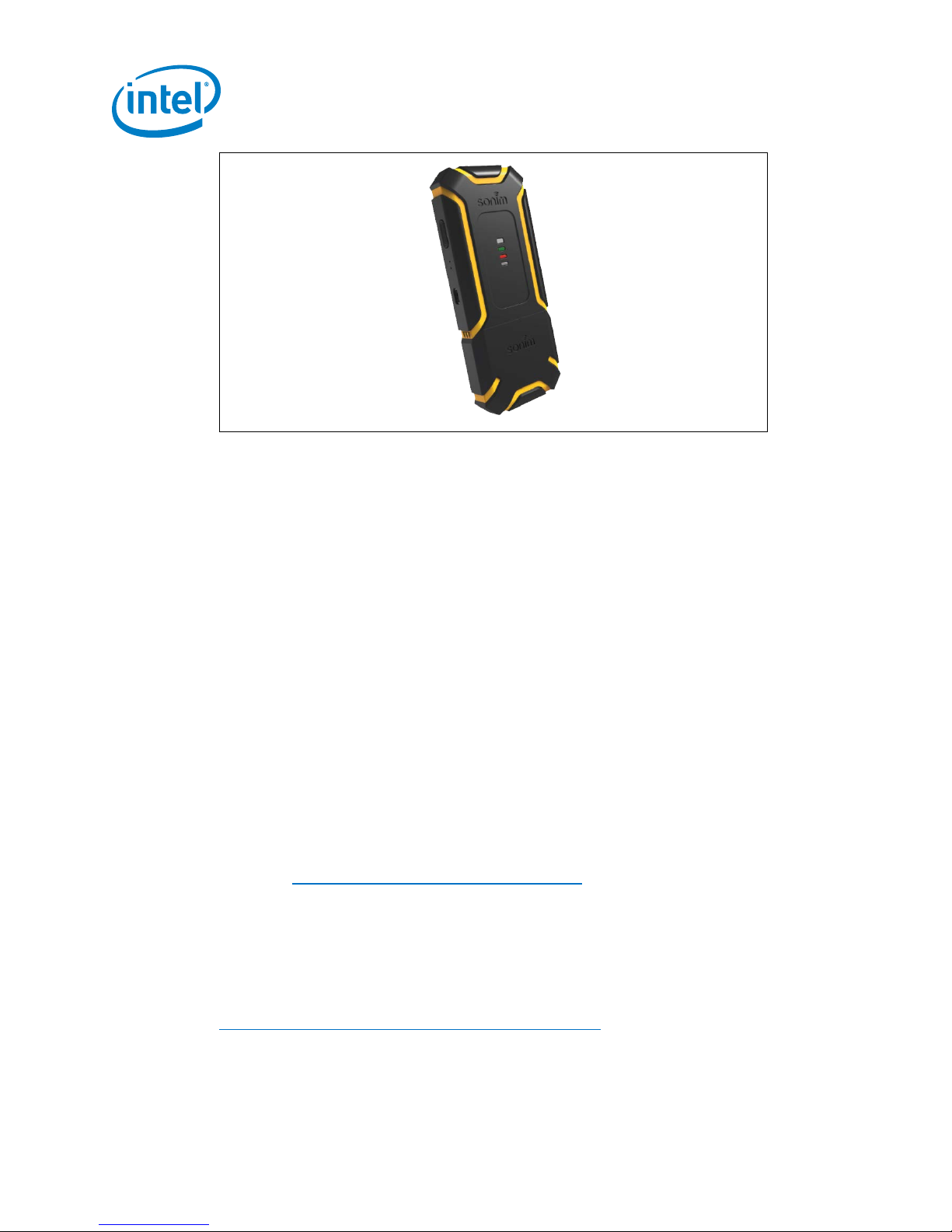
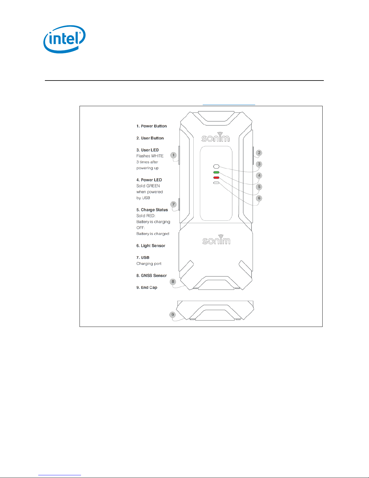
Figure 1. Sonim* XPi Device
1.1 What’s in the Box?
Verify the components you received:
Introduction
• Sonim XPi* device with GNSS module attached
• End cap
• Info sheet
The battery is a 1400mAH Li-Ion battery rechargeable via power supply.
Note:
1. The 5 V/0.5 A power supply and Micro USB Cable must be purchased separately.
2. The device should be fully charged before use, using a power supply. It is not intended
to be charged using a computer USB.
3. If you wish to remove the GNSS module, you need a Phillips head screwdriver.
1.2 Support
For technical support:
1. Go to: https://marketplace.att.com/support
2. Select Sonim XPi in the drop-down menu and access:
• Latest User Guides
• Support Ticketing
• Live Chat
• Knowledge Base
For product-specific information and documentation, go to:
https://marketplace.att.com/products/sonim-xpi
Sonim* XPi
User Guide December 2017
8 Document Number: 336569 Rev 1.0
Page 9

Introduction
1.3 Terminology
The following acronyms and terms are used in this document:
Table 1. Terminology
Term Description
API Application Programming Interface
FCC Federal Communications Commission
GNSS Global Navigation Satellite System
Intel® DMS Intel® Device Management Service
Intel® LIQD Intel® LTE IOT Quick Deployment
IoT Internet of Things
LTE Long-Term Evolution
M2X AT&T Data Storage Service For Internet Connected Machine-To-
Machine Devices
RSSI Received Signal Strength Indication
§
Sonim* XPi
December 2017 User Guide
Document Number: 336569 Rev 1.0 9
Page 10
2.0 Quick Setup
This section provides details on account set up, device setup, and viewing device data.
It also includes a reference to the User Guide for detailed information on the Sonim XPi
device.
2.1 Account Setup
Follow these steps to set up the Sonim XPi device:
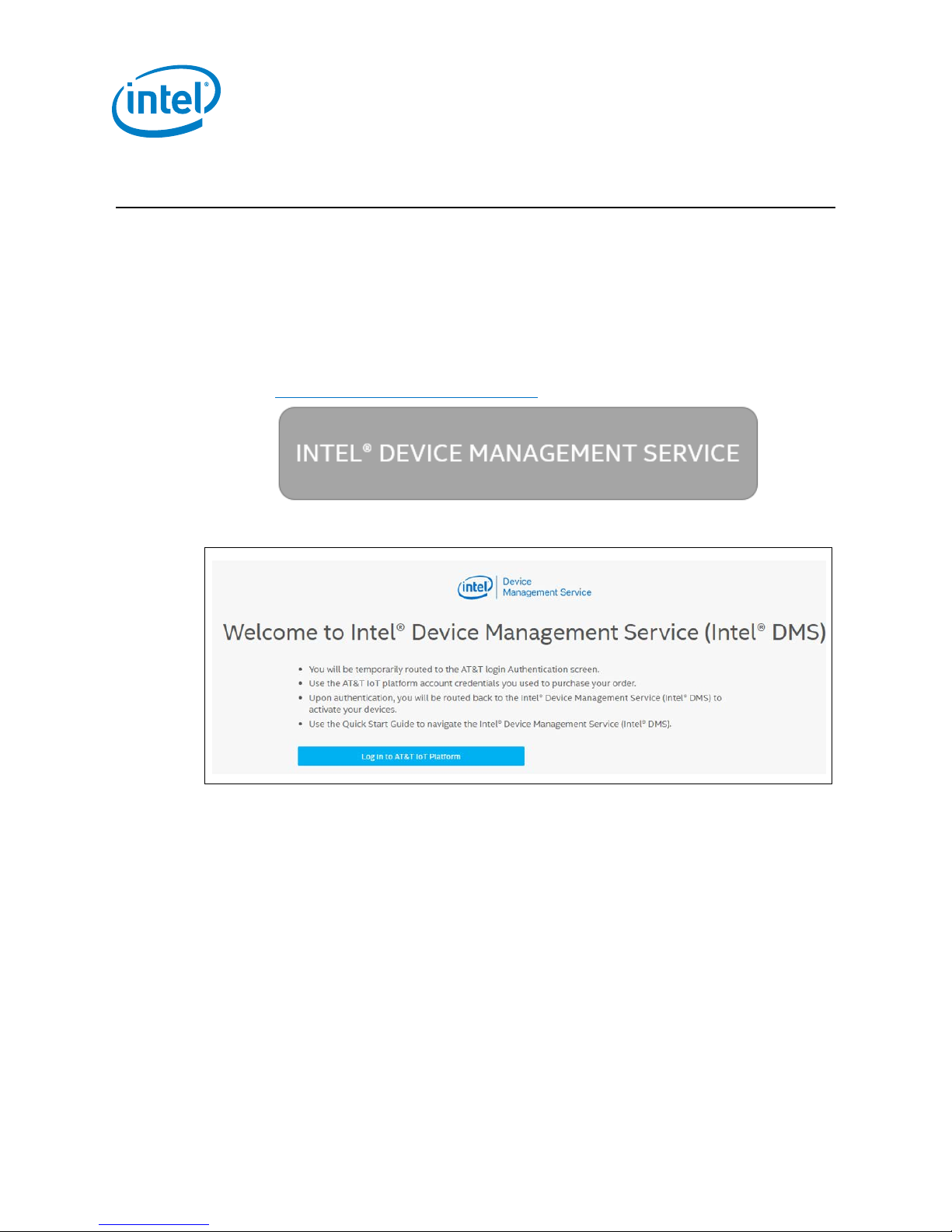
1. Access the Intel® Device Management Service at:
https://devicemanagement.intel.com or click this button:
2. Click the button to log in to the AT&T IoT Platform.
Quick Setup
Figure 2. Log in to AT&T IoT Platform
Sonim* XPi
User Guide December 2017
10 Document Number: 336569 Rev 1.0
Page 11
Quick Setup
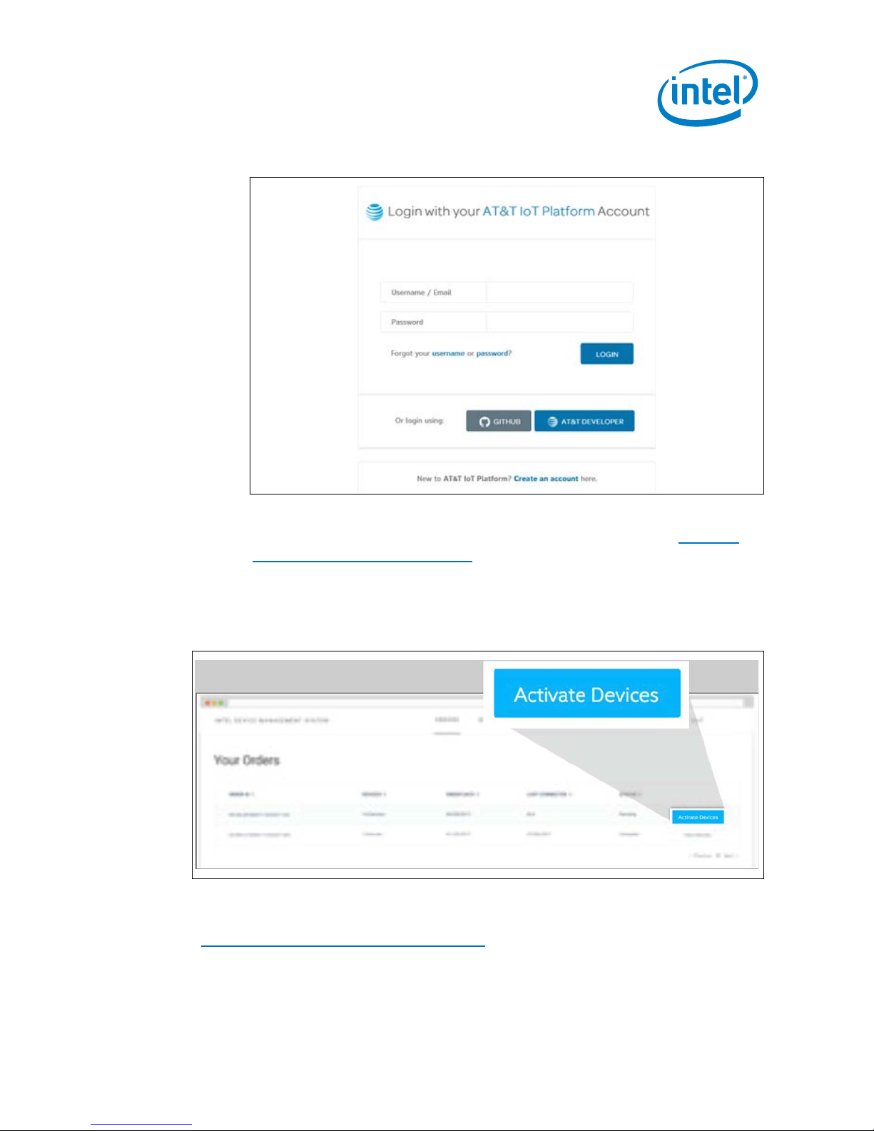
3. Enter the AT&T IoT account credentials that were used when purchasing your
devices.
Figure 3. Enter AT&T IoT Account Credentials
You are routed to Intel® DMS to activate your devices. Refer to the
Using the
Intel® Device Management Service section for details.
Note: If you do not have a user name and password for the AT&T IoT account, contact the
person who purchased the devices for your company.
4. Click ‘Activate Devices’ to activate all of the devices in your order.
Figure 4. Activate Devices button
You are routed to the Devices tab of the Intel® DMS. For details on using Intel® DMS, see
Using the Intel® Device Management Service
Sonim* XPi
December 2017 User Guide
Document Number: 336569 Rev 1.0 11
.
Page 12
2.2 Device Setup
To view data, users need to power on and sync the device.
1. Power on the device:
• Press and release the Power Button
OR
• Connect the device to a power supply (5V) via the Micro USB connector
The User LED flashes white 3 times to indicate the device is powering up. If the User
LED flashes red 3 times, the device is already ON. Refer to Power On the Device
Note: The device stays awake for 20 seconds after power-on or waking up.
2. To sync the device, press the User Button within 20 seconds of turning on or
waking up the device. It can take up to 60 minutes for data to arrive. The User
LED flashes green once data is successfully sent to M2X.
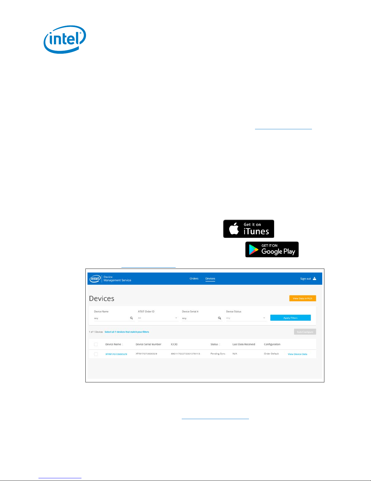
2.3 View Device Data
Users can view device data in two ways:
1. Download the Intel® LTE IoT Display App
Quick Setup
.
• iTunes (iOS versions 9-11 are supported)
• Google Play (Android versions 6-7 are supported).
2. . Use the AT&T* M2X website
Figure 5. View Device Data
The top portion of the screens offers a flexible search form with several fields to enter
search criteria. This section allows users to search using their own criteria or using the
drop-down menu options. Refer to Device Search Capability
.
.
Sonim* XPi
User Guide December 2017
12 Document Number: 336569 Rev 1.0
Page 13

Quick Setup
Clicking transfers you to the M2X page for that specific device.
Clicking transfers you to the M2X page listing all your devices.
2.4 References
For a comprehensive understanding of the Sonim XPi device, refer to the Sonim XPi
User Guide at https://marketplace.att.com/products/sonim-xpi
This document includes information on:
• Using the device, including:
o Powering on, off, charging, waking up the device
o LED indicators and Button behavior
o Removing the GNSS Module
• Using the Intel® Device Management Service, including:
o Device orders
o Devices
• Viewing Device Data
• Using the Intel® LTE IoT Display App
• FAQs
.
§
Sonim* XPi
December 2017 User Guide
Document Number: 336569 Rev 1.0 13
Page 14
3.0 Using the Sonim XPi
Devices are partially charged and ready to be activated. Be sure to charge it fully before
use. By default, all sensors are enabled and the default interval for data upload is 15
minutes. For more information, refer to the Configure Device(s)
Using the Sonim XPi
section.
Figure 6. Sonim XPi device
The atmospheric pressure and temperature sensors need to access outside air.
These sensors are placed near the enclosure edge of the Sonim XPi device with 2 holes
between the Power Button and the USB Charging Port (See Figure 1). The holes allow
outside air to enter. A mesh behind the holes restricts fluid ingress but allows airflow.
Note: Be careful not to cover the two small holes on the device between the Power Button
and USB Charging port. Doing so can affect sensor readings.
Sonim* XPi
User Guide December 2017
14 Document Number: 336569 Rev 1.0
Page 15

Size
101mm x 57mm x25mm
Weight
Sonim XPi: 126 g
Sonim XPi + Expansion GNSS Sensor Board: 164 g
Certifications
FCC PTCRB
Operating
Storage
For 6 months:+15° C to +25° C
Using the Sonim XPi
Table 2. Sonim* XPi Characteristics
Expansion GNSS Sensor Board: 42g
temperature
temperature
Charging temperature: 0 to 60° C
Discharging temperature: -20° C to 60° C
For a month: -20° C to 45° C
3.1 Power on the Device
There are 2 ways to power on the device:
• Press and release the Power Button
OR
• Connect the device to a power supply (5V) via the Micro USB connector
After approximately 6 seconds, the User LED flashes white 3 times to indicate the
device is powering up. See Figure 6.
If the User LED flashes red 3 times, the device is already ON.
• If the device is connected to a power supply, the Power LED is green.
• If the device is running on battery, NO LED is illuminated.
Note: The device stays awake for 20 seconds after power-on or waking up.
3.2 Power off the Device
Press and hold the Power Button for 10 seconds, until the Red LED stops flashing.
If the device was powered on by connecting to a power supply, it powers off when it is
disconnected.
3.3 Charge the Device
The device can be charged with a 5 V/0.5 A power supply and Micro USB Cable,
purchased separately.
The Charge Status LED is RED until it is fully charged, at which time the LED turns off.
3.4 Wake Up the Device
The device goes to sleep between sensing intervals. You may want to wake the device
to force a configuration update and, if there is buffered data, a sensor upload to M2X.
Sonim* XPi
December 2017 User Guide
Document Number: 336569 Rev 1.0 15
Page 16

To wake the device, press and quickly release the Power Button. This wakes the device
for 20 seconds.
3.5 Device Battery
The device battery life guidelines are estimates as shown in Table 3. Actual battery life
may vary based on additional factors such as total device life and operation
temperatures.
Table 3. Battery Life Guidelines
Using the Sonim XPi
Length of time
battery holds
charge
2 days 5 minutes 5 minutes 5 minutes
14 days 15 min 1 hour 1 hour
6 months 1 hour (only
Note: If the Battery Charge Level sensor is enabled in Intel® DMS, you can view and track the
devices battery usage level.
3.6 LED Indicators
Figure 6 illustrates the LED indicators of the device.
3.6.1 Charge Status LED
Table 4. Charge Status LED Indicators
Charging LED Behavior
Solid RED Battery is charging
OFF Battery is charged
Sensor reading
interval
Temperature and
Humidity sensors
enabled)
Upload interval GNSS
1 day Not fitted or fitted
but not used
3.6.2 Power LED
Table 5. Power LED Indicators
GREEN The device is plugged in to the power supply
Sonim* XPi
User Guide December 2017
16 Document Number: 336569 Rev 1.0
Power LED Behavior
Page 17
Using the Sonim XPi
3.6.3 User LED
Table 6. User LED Indicators
User LED Behavior
Flashing WHITE quickly 3 times Powering up
Flashing RED every second Button held while powering down the device
GREEN for half a second Data is successfully sent to M2X
RED for half a second There is no connection the cloud. To
3.7 Button Behavior
Figure 6 illustrates the buttons of the device.
3.7.1 User Button
Before performing any action, press and release the Power Button to ensure the system
is awake.
troubleshoot, see FAQ
Table 7. User Button Behavior
User Button Behavior
Button is pressed and released An immediate connection attempt to the Cloud server is
3.7.2 Power Button
Table 8. Power Button Behavior
Power Button Behavior
Button is pressed and held for 10
seconds
Button is pressed and released The device wakes up and does not go back to sleep for
made, initiating a configuration check and transfer of
sensor data. The transfer only happens if sensor data is
buffered since the last upload.
Note: The User LED is GREEN for half a second when data
is successfully sent to the cloud.
Note: On pressing the User Button, the User LED is WHITE
for 100ms. This LED display indicates that the button
press has been detected.
Device powers down.
The User LED flashes RED every second while the Button
is held.
20s.
The User LED flashes RED 3 times to indicate the device
has woken up
Sonim* XPi
December 2017 User Guide
Document Number: 336569 Rev 1.0 17
Page 18
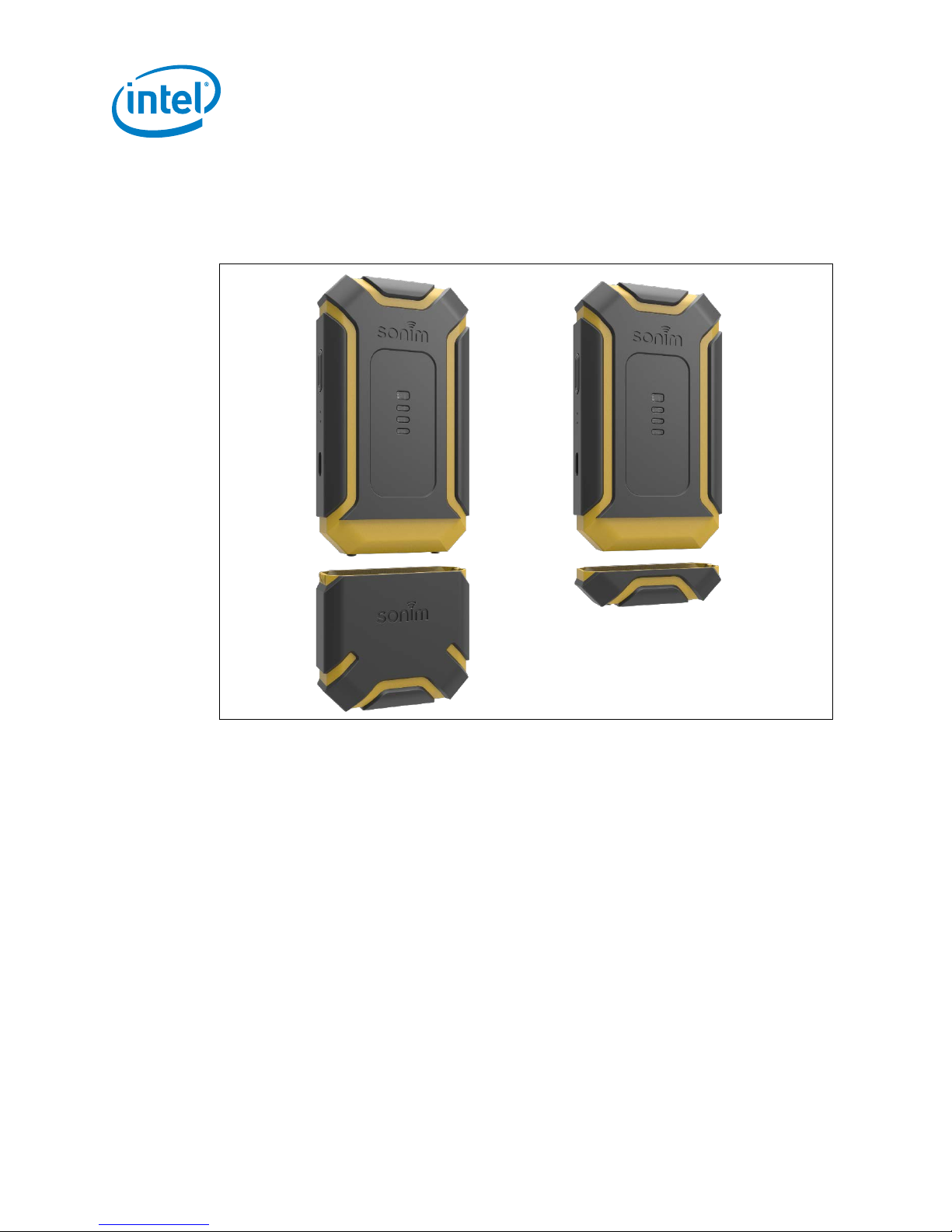
3.8 Remove the GNSS Module
The two Phillip’s head screws at the bottom of the GNSS module can be unscrewed and
the module removed. The included end cap can then be screwed on, if GNSS is not
required, to protect the pins.
Using the Sonim XPi
Figure 7. Removing the GNSS Module
Sonim* XPi
User Guide December 2017
18 Document Number: 336569 Rev 1.0
Page 19

Using the Sonim XPi
3.9 Attach the Device
Use suitable M2 machine screws to attach the device as shown in Figure 8. The distance
between the two screws is 12 mm. The length of the screws depends on the asset to
which the device is being attached.
Figure 8. Attach the device
For Sonim XPi Mounting Options, refer to Appendix B
.
§
Sonim* XPi
December 2017 User Guide
Document Number: 336569 Rev 1.0 19
Page 20

Using the Intel® Device Management Service
4.0 Using the Intel® Device Management Service
The Intel® Device Management Service (https://devicemanagement.intel.com/) can be
used to activate and configure Sonim XPi devices.
To login, select the ‘Log in’ button on the top right of the screen or the ‘Login to AT&T
IoT Platform’ button.
Figure 9. Intel® DMS login screen
You are routed to the AT&T IoT Platform. Enter the credentials for your AT&T IoT
account that were provided during the device order process.
Figure 10. AT&T IoT Platform Login Screen
After entering valid M2X credentials, you are routed back to the Intel® DMS main
interface.
Sonim* XPi
User Guide December 2017
20 Document Number: 336569 Rev 1.0
Page 21

Using the Intel® Device Management Service
4.1 Device Orders
The Orders tab allows you to:
• View status of their device orders. Possible order states of the devices are:
− Completed
− In Progress
− Pending
• Complete order activation for Pending orders
• View the Devices on the Order
4.1.1 Order Fields
Figure 11. Order Fields
A. AT&T Order ID: The AT&T Order Number assigned when the order was made
B. Devices: The number of devices included on the order
C. Order Date: The date the order was made
D. Activation Date: The date the devices on the order were activated
E. Status: The status of the order
Sonim* XPi
December 2017 User Guide
Document Number: 336569 Rev 1.0 21
Page 22

4.1.2 Activate an Order
To activate all the devices associated with a specific AT&T Order ID, select the Order ID
in the ‘Orders’ tab and click ‘Activate’.
Figure 12. Activate an Order
Using the Intel® Device Management Service
Click the button next to the device you want to activate. Once you have
activated your devices, you can view their status.
Note: All devices within an order are activated at the same time. Once an order is activated,
you are routed to the 'Devices' screen where all devices on the order are listed.
4.1.3 View the Devices on an Order
To view all the devices associated with a specific AT&T Order ID, select the Order ID in
the ‘Orders’ tab and click ‘View Devices’. You are routed to the ‘Devices’ tab where all
the devices for that order are listed.
Figure 13. View Devices
Sonim* XPi
User Guide December 2017
22 Document Number: 336569 Rev 1.0
Page 23
Using the Intel® Device Management Service
4.2 Devices
From the Devices tab, you can:
• View the list of current devices
• View the configuration for any device
• Update the configuration for a device
• Update the configuration for a range of devices
• Click through to M2X to view device data
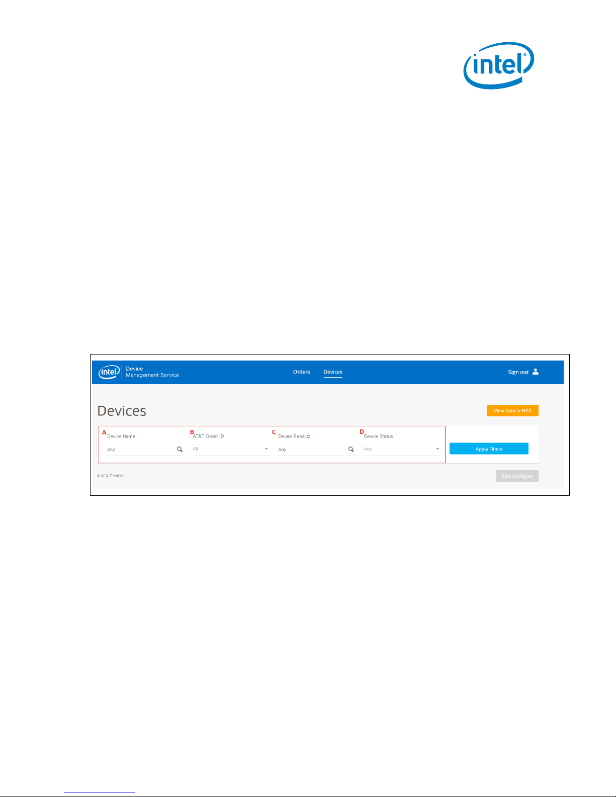
4.2.1 Device Search Capability
A flexible search form provides several fields to enter search criteria.
Enter criteria in a field and apply search criteria by clicking the Apply Filters button to
query the fields for the results. You can also use the drop-down menus to select a
specific AT&T Order ID or view by Device Status. You can search using more than one
search field.
Click the Remove Filter button next to the field to clear all criteria, and show all
records.
Figure 14. Device Search Fields
A. Device Name: This is the Name assigned to the Device. By default, this is the
Serial Number. Users can edit this field to adopt a more user-friendly name.
B. AT&T Order ID: The AT&T Order Number assigned to the Order
C. Device Serial #: Serial Number of the device. The Serial Number is printed on
the back of the device.
D. Device Status: Current Status of the device
Sonim* XPi
December 2017 User Guide
Document Number: 336569 Rev 1.0 23
Page 24

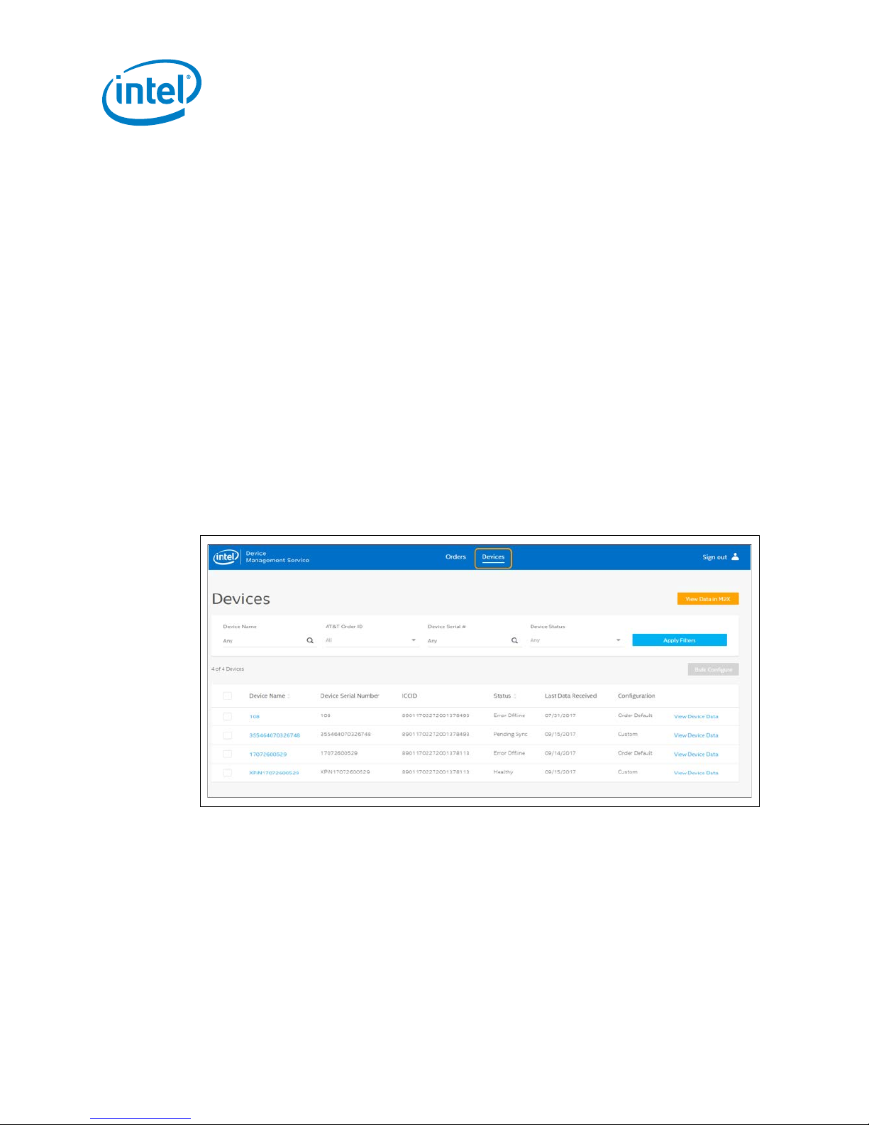
4.2.2 Device Fields
Note: A Device Status of Healthy indicates that the Device is Online
sensor data to M2X.
Figure 15. Device Fields
A. Device Name: This is the Name assigned to the Device. By default, this is the
Device Serial Number but it can be edited to a more user-friendly name.
B. Device Serial Number: Serial Number of the device. The Serial Number is
printed on the back of the device.
C. ICCID: The ICCID associated with the e-sim on the device
D. Status: Current Status of the device. The possible states are:
o Not Activated: The Device has not been activated or device activation
o Healthy: The Device is communicating with the Intel® DMS
Using the Intel® Device Management Service
failed
and communicating successfully with the Intel® DMS. It is not an
indication that the device is successfully collecting and uploading
o Pending Sync: The most recent configuration change has not been
synced to the device
o Sync Error: The most recent configuration change was scheduled over
4 hours ago and failed to sync to the device
o Error Offline: The device is not communicating with the Intel® DMS
o Offline: The device has not reported to the Intel® DMS for 4 hours since
the last data upload. This status also indicates that no configuration
update is pending.
E. Last Data Received: The date of the most recent successful communication
with the device.
F. Configuration: There are 2 possible values for the Configuration setting:
o Order Default: Indicates that the device is using the factory default
settings.
o Custom: Indicates that device configuration has been updated from the
factory defaults.
Sonim* XPi
User Guide December 2017
24 Document Number: 336569 Rev 1.0
Page 25

Using the Intel® Device Management Service
4.2.3 Configure Device(s)
Click the ‘Device Name’ on the ‘Devices’ tab to view the current device configuration.
Configuring a device allows users to:
• Change the device name, if needed
• Reset all settings to factory defaults
• Enable or disable each of the sensors via the On/ Off Status toggle
• Change the sensor reading frequency for each sensor. This refers to the frequency
at which the data from each sensor is read.
• Change the reporting interval, that is, how often data collected by the sensors is
sent to the cloud.
4.2.3.1 Default Configuration
Devices are shipped with default configuration settings as shown in Figure 16.
Figure 16. Device Configuration Panel
Sonim* XPi
December 2017 User Guide
Document Number: 336569 Rev 1.0 25
Page 26
A. The default value of the ‘Name’ field is the device Serial Number. This can be edited
to a more user-friendly name.
B. RSSI is enabled by default and cannot be disabled. The RSSI is measured when a
network connection is established, based on the selected reporting interval, power
on and manual sensor upload.
C. Battery On Charge Indicator is not directly configurable using the Intel® DMS UI and
takes its configuration from the Battery Charge Level. If the Battery Charge Level on
Intel® DMS is disabled, no values are reported to the ‘Charging’ stream on M2X.
Possible Values for the Battery Charge Indicator are ON (1) or OFF (0).
D. The default reporting Interval is 1 hour.
E. The default Sensor Reading Frequency is 15 minutes.
F. All sensors are enabled by default (ON).
G. The ‘Reset to Factory Default’ button resets your device sensor and upload interval
settings to the default settings.
Note: ‘Reset to Factory Default’ button has no effect on the device name setting.
4.2.3.2 Configure a Single Device
To custom configure your devices individually:
1. Log in to the Intel® Device Management System (Intel® DMS) using your AT&T IoT
Platform Account credentials.
2. From the Devices screen, click the device name to see data for one device.
Using the Intel® Device Management Service
Figure 17. Devices Menu
3. Select the Device to be configured by clicking the ‘Device Name’ on the ‘Devices’
tab.
Sonim* XPi
User Guide December 2017
26 Document Number: 336569 Rev 1.0
Page 27

Using the Intel® Device Management Service
Figure 18. Configuring a Single Device
The configurable fields are:
• Name: To change the device name click ‘Edit’ enter your new device name and
click ‘Save’ to save the change.
• Sensor Status: Toggle the Sensor Status button to the desired position
(ON/OFF) to enable/disable a sensor.
• Reporting Interval: To change the Reporting interval, enter the desired value in
the dialog box and select Minutes/Hours/Days from the dropdown. Minimum
Reporting Interval is 5 minutes.
• Sensor Reading Frequency: To change the Sensor Reading Frequency, enter
the desired value in the dialog box and select Minutes/Hours/Days from the
dropdown. Minimum Sensor Reading Frequency is 5 minutes.
4. Once the required changes have been made, click ‘Apply’ to save the new
configuration.
Note: If the Sensor Reading Frequency is set too low relative to the Reporting Interval,
you may lose data as older readings are overwritten by new ones. A maximum 90
sensor readings can be stored before they are overwritten.
Choosing settings that can lead to data loss generates a warning to users as shown in
Figure 19. Settings that would queue over 90 readings for a sensor in a reporting
interval, thereby causing data loss, cannot be saved. The Apply button on the screen is
grayed out, as shown in Figure 19. However the calculation used does not account for
M2X upload failures or network connection failures. To enable the Apply button, the
configuration needs to be changed to within the intervals noted above.
Sonim* XPi
December 2017 User Guide
Document Number: 336569 Rev 1.0 27
Page 28

Using the Intel® Device Management Service
Figure 19. Data Loss Warning
Sonim* XPi
User Guide December 2017
28 Document Number: 336569 Rev 1.0
Page 29

Using the Intel® Device Management Service
4.2.3.3 Bulk Configure Devices
You can also select multiple devices and select ‘Bulk Configure’ to apply the same
configuration to the selected devices.
To Bulk Configure ALL devices on a page, check the box beside the ‘Device Name’ (A)
field at the top of the page and select ‘Bulk Configure’ (B).
Note: If you click the select all box at the top of the page (A) and your devices span more than
one page, you need to configure each page separately.
Figure 20. Bulk Configure Devices
Sonim* XPi
December 2017 User Guide
Document Number: 336569 Rev 1.0 29
Page 30

5.0 Viewing Device Data
You can access your device data via M2X at https://m2x.att.com.
5.1 View Device Data in M2X
When a device is powered on, it connects to Intel® DMS to download its configuration,
which includes the M2X Credentials. If the device has successfully connected to the
Intel® DMS, it shows a ‘Healthy’ status.
The Device then takes an initial reading from all enabled sensors and uploads the
readings to M2X. To verify that the sensor data has been successfully uploaded, select
the device from the ‘Devices’ tab and click ‘View Device Data’.
Viewing Device Data
Figure 21. View Device Data in M2X
Clicking ‘View Device Data’ redirects you to the M2X page for that specific device
(https://m2x.att.com/devices/<device_id>).
Clicking ‘View Data in M2X’ redirects you to the M2X page listing all your devices.
Data successfully uploaded appears graphed on the page.
Sonim* XPi
User Guide December 2017
30 Document Number: 336569 Rev 1.0
Page 31

Viewing Device Data
Figure 22. M2X Stream Data
Note: On the default Factory Configuration, ALL sensors are enabled.
Note: The Device can be identified via the Serial Number printed on the back.
5.2 View Data in AT&T Asset Management Operation Center
(AMOC)
Monitor, manage, and analyze data from Sonim XPi device with AT&T Asset
Management Operation Center (AMOC) – A simple intuitive web based tool. View
sensor data such as temperature, humidity, geographical coordinates, peak shock,
battery charge for multiple Sonim XPi devices and also set alerts to spot and resolve
issues before they affect operations. Access to AMOC is included in the monthly
subscription plan for Sonim XPi. AMOC can be
https://marketplace.att.com/
Refer to Appendix E: AT&T Asset Management Operation Center
after the device has been purchased.
accessed at AT&T IoT Marketplace
for details.
§
Sonim* XPi
December 2017 User Guide
Document Number: 336569 Rev 1.0 31
Page 32

Using the Intel® LTE IoT Display App
6.0 Using the Intel® LTE IoT Display App
The Intel® LTE IoT Display App allows you to view real-time sensor data generated by
Sonim* XPi devices.
Use the app to view data, create Triggers, and receive alerts via push notification when
a trigger is activated.
1. Download the Intel® LTE IoT Display App
• iTunes (iOS versions 9-11 are supported)
• Google Play (Android versions 6-7 are supported).
2. Complete the steps to set up the device
The following sections provide support using the Intel® LTE IoT Display App.
.
6.1 Splash Screen
When opening the app, you will see the splash screen as shown in Table 9.
Table 9. Splash Screen
Screen iOS view Android view
Opening screen
Sonim* XPi
User Guide December 2017
32 Document Number: 336569 Rev 1.0
Page 33

Using the Intel® LTE IoT Display App
6.2 Account Set Up
Table 10. Account Set Up
Screen iOS view Android view
Set up your AT&T IoT
Platform Account.
Sonim* XPi
December 2017 User Guide
Document Number: 336569 Rev 1.0 33
Page 34

6.3 Account Log In
Table 11. Account Log In
Screen iOS view Android view
Log In to your AT&T IoT
Platform Account.
Use the same account you
used to purchase your
Sonim XPi devices.
Using the Intel® LTE IoT Display App
Sonim* XPi
User Guide December 2017
34 Document Number: 336569 Rev 1.0
Page 35

associated with it.
Using the Intel® LTE IoT Display App
6.4 Device Location
Table 12. Device Location
Screen iOS view Android view
View the Location of your
Devices.
Once you have signed in,
the app shows you the
Devices view. By default,
this view shows the
geographic location of all
your devices on a map.
You can also access the
Menu button, Sensors
button, Refresh button and
Show List tab on this
screen.
Access device details by
tapping each device on the
map.
Blue dots indicate devices
and their location. A red dot
indicates a device that
currently has an alert
Sonim* XPi
December 2017 User Guide
Document Number: 336569 Rev 1.0 35
Page 36

6.5 Device List
Table 13. Device List
Screen iOS view Android view
Tap the Show List button at
the bottom of the Devices
view to see the Device List.
The Device List shows all
the devices registered to
your account. Each row
also displays the last time
sensor data was reported
from each device.
Tap on a device to view its
details.
Using the Intel® LTE IoT Display App
Sonim* XPi
User Guide December 2017
36 Document Number: 336569 Rev 1.0
Page 37

Using the Intel® LTE IoT Display App
6.6 Sensor Data
Table 14. Sensor Data
Screen iOS view Android view
You can access the current
sensor data for each device
on the map.
Tap the Sensors button on
the top right side of the
title bar to see a list of
sensor data types. These
are shown in both the map
as well as the list views.
You can see one sensor at a
time in this view.
Sonim* XPi
December 2017 User Guide
Document Number: 336569 Rev 1.0 37
Page 38

6.6.1 Sensor Data Map Example
Table 15. Sensor Data Map Example
Screen iOS view Android view
Here is an example of
devices located
geographically across the
US.
The Show List button at the
bottom of the screen
displays a list of the
devices and their
corresponding sensors.
Using the Intel® LTE IoT Display App
Sonim* XPi
User Guide December 2017
38 Document Number: 336569 Rev 1.0
Page 39

Using the Intel® LTE IoT Display App
6.6.2 Sensor Data List Example
Table 16. Sensor Data List Example
Screen iOS view Android view
Here is an example of the
list of sensor data.
If a sensor is selected, you
will see the last activity
time as well as the most
recent value for that
sensor.
Sonim* XPi
December 2017 User Guide
Document Number: 336569 Rev 1.0 39
Page 40

6.7 Device Details
Table 17. Device Details
Screen iOS view Android view
Tap one of your devices in
the Device List or on the
map to see the Device
details.
By default, this view shows
the most recently reported
values reported by the
device.
Tap the Clock icon or
‘Current’ to view historical
data.
Using the Intel® LTE IoT Display App
Sonim* XPi
User Guide December 2017
40 Document Number: 336569 Rev 1.0
Page 41

Using the Intel® LTE IoT Display App
6.8 Viewing Historical Data
Table 18. Viewing Historical Data
Screen iOS view Android view
Tap on the Clock icon in
the top left to change this
value.
The time period may be set
to Current, a collection of
recent values, or all values
from a particular period of
time.
Select a time period to view
sensor information in graph
format.
Sonim* XPi
December 2017 User Guide
Document Number: 336569 Rev 1.0 41
Page 42

6.8.1 Viewing a Range of Sensor Data
Table 19. Viewing a Range of Sensor Data
Screen iOS view Android view
Scroll to view the data for
all the sensors.
Using the Intel® LTE IoT Display App
View details of records
shown on the graph by
tapping on the sensor
name or Record Count bar.
Sonim* XPi
User Guide December 2017
42 Document Number: 336569 Rev 1.0
Page 43

Using the Intel® LTE IoT Display App
6.9 Triggers
Table 20. Triggers
Screen iOS view Android view
To view existing or create a
new trigger, tap the
Triggers tab.
Triggers allow you to
receive notifications when a
sensor hits a particular
threshold.
When this happens, the
device trigger status is
known as activated.
Devices with triggers in the
activated state have red
map pins on the Devices
view and sensor details are
shown in red.
6.9.1 Adding a Trigger
Table 21. Adding a Trigger
Screen iOS view Android view
Tap Add Trigger to add a
trigger for your device.
You must enter the
following information to
save a new trigger:
• Trigger Name (user
determined)
• One or more Conditions,
with the following values:
Sensor (
Ambient light (lux)
Atmospheric
pressure (mbar)
Battery (%)
Humidity (%)
Peak shock (G)
Sonim* XPi
December 2017 User Guide
Document Number: 336569 Rev 1.0 43
Page 44

Using the Intel® LTE IoT Display App
Signal Strength (dB)
Screen iOS view Android view
In this example, the trigger
is named Melting Point, the
user is tracking their
product shipments for
changes to chemistry in
their product.
Responding to a Trigger
Push Notification
If you choose to open a
push notification from a
trigger, the app will open
and take you to the Device
Detail view for the device
associated with that trigger.
Temperature
(degrees Celsius)
Condition (more than,
less than or equal to)
Threshold Value (a
number)
Reset Condition (a
number) (optional; if
not used, the reset
condition is the
threshold value)
Notification frequency
(select between
periodic, continuous,
or single)
Sonim* XPi
User Guide December 2017
44 Document Number: 336569 Rev 1.0
Page 45
Using the Intel® LTE IoT Display App
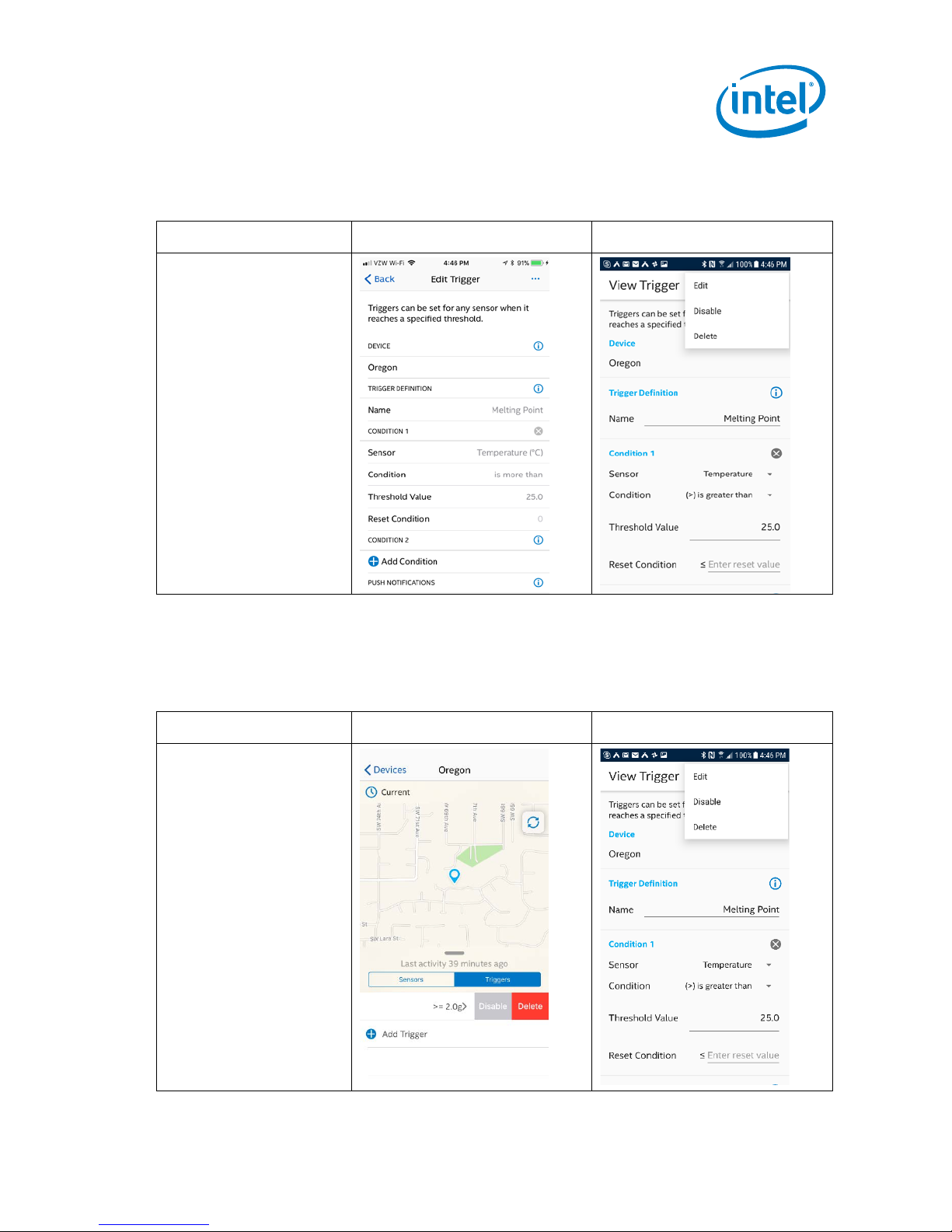
6.9.2 Editing a Trigger
Table 22. Editing a trigger
Screen iOS view Android view
In iOS: Tap to edit the
trigger, make your updates,
and save on the top right.
Tapping cancel will
abandon your changes.
In Android: users tap the
Menu button on the top
right, and select Edit from
the drop-down menu.
6.9.3 Disabling a Trigger
Table 23. Disabling a Trigger
Screen iOS view Android view
In iOS: users swipe on the
device detail and then tap
on the Disable button to
disable the trigger.
In Android: users tap the
Menu button on the top
right, and select Disable
from the drop-down menu.
Sonim* XPi
December 2017 User Guide
Document Number: 336569 Rev 1.0 45
Page 46

6.9.4 Deleting a Trigger
Table 24. Deleting a Trigger
Screen iOS view Android view
In iOS: users swipe on the
device detail and then tap
the Delete button to delete
the trigger.
In Android: users tap the
Menu button on the top
right, and select Disable
from the drop-down menu.
Using the Intel® LTE IoT Display App
Sonim* XPi
User Guide December 2017
46 Document Number: 336569 Rev 1.0
Page 47

Tap the Menu icon in the
out.
Using the Intel® LTE IoT Display App
6.10 Help, Settings, and Sign Out
Table 25. Help, Settings, and Sign Out
Screen iOS view Android view
top left of the Devices
view to view app
navigation options.
You can tap Help to view
information about the
LIQD service including
user guides.
Settings allows you to
select or deselect Push
Notification permissions
for the app.
Tap Sign Out to end your
session or allow you to
sign into a different
account. The app keeps
you logged into your
account even if you close
the app without signing
Sonim* XPi
December 2017 User Guide
Document Number: 336569 Rev 1.0 47
§
Page 48

Appendix A FAQ
How do I power OFF the Sonim XPi?
A.1 AT&T
Where do I buy the Sonim XPi? AT&T IoT Marketplace
What is included in the Sonim XPi
purchase price?
I have not received my confirmation
email. What should I do next?
Can I use my existing AT&T IoT
Platform account?
Why do I not see my order in Intel®
Device Management Service?
What are the data charges for Sonim
XPi?
When do I get charged for data? On a monthly basis.
How do I contact AT&T Support? Contact Support at
FAQ
Device and extension and mobile app
Contact Support at
https://marketplace.att.com/support
Yes, the same account you use to purchase the
device on IoT Marketplace
Contact Support at
https://marketplace.att.com/support
Details on subscription plans for Sonim XPi available
at marketplace.att.com/products/sonimXpi
https://marketplace.att.com/support
A.2 Sonim
How do I power ON the Sonim XPi? To power on the device either:
• Press and release the Power Button (for half a
second or more)
• Connect the device to a power supply (5V) via the
Micro USB connector
The device takes approximately 6 seconds to boot
up. The User LED flashes WHITE 3 times when the
Firmware Application starts.
If the device was powered on using the Power Button:
• Press and hold the Power Button. The User LED
flashes RED 10 times as the device powers down.
When the LED stops flashing release the Power
Button.
If the device was powered on using power supply
either:
• Press and hold the Power Button.
OR
• Remove the power supply.
Sonim* XPi
User Guide December 2017
48 Document Number: 336569 Rev 1.0
Page 49

What information is available on the
FAQ
How do I tell if the Sonim XPi is
running?
Press and release the Power Button. If the User LED
immediately flashes RED 3 times the device is
running.
Why does it take so long to turn off
the device?
The device must perform a graceful disconnect from
the network, which causes a short delay.
How do I charge the Sonim XPi? Connect it to a power supply (5V) via the Micro USB
connector.
What is the capacity of the Sonim
XPi battery?
How long will the Sonim XPi run on
battery under normal operating
conditions?
How do I tell if Sonim XPi battery is
fully charged?
The battery is a 1400mAH Li-Ion Battery
rechargeable over power supply.
This depends on how the device is configured;
anywhere from 2 days to 6 months. Refer to Table 1
for details.
If the Charging LED is OFF when the device is
connected to power supply, the battery is fully
charged.
How do I track the Battery Usage of
the Sonim XPi device?
If the 'Battery Charge Level' sensor is enabled, the
Battery % is reported.
This sensor can be enabled in the Intel® DMS or the
M2X.
How do I attach/detach the GNSS
Sensor Module to/from the Sonim
XPi?
The GNSS Sensor Module can be removed by
unscrewing the two screws at the end of the device.
Attach the end cap if using without the GNSS Sensor
Module, to protect the connector from dust and
liquid contamination.
Why are the User Button Functions
not working when the Sonim XPi is
running on Battery?
I’ve enabled the location sensor, and
I am connecting to the Cloud, but I
am not seeing any location sensor
The Power Button must be pressed and released to
wake the device before the User Button Functions
can be used.
GNSS location services rely on orbiting satellites. If
you are not outside or close to a window, the satellite
reception is blocked.
data in M2X. Why?
Why is no sensor data uploaded to
M2X on User Button press and
release?
There may not be any sensor data stored on the
device since the previous upload.
Check the time of the previous upload and the sensor
collection interval.
Why does the User LED flash RED at
the Data Upload Interval?
This indicates that a connection to M2X or the DMS
could not be established, or there is no network
connectivity.
What does the flashing GREEN LED
This indicates a successful upload to M2X.
at Sensor Upload interval indicate?
Sonim XPi?
Sonim* XPi
December 2017 User Guide
Document Number: 336569 Rev 1.0 49
• Ambient Light sensor
• Humidity sensor
• Barometric Pressure sensor
• Vibration sensor
• Temperature sensor
• Location sensor
• Battery Charge Level
Page 50

• Battery on Charge Indicator
• Received Signal Strength Indication (RSSI)
What happens to Sensor Data on the
device if the connection to M2X
fails?
How much sensor data can be stored
on the Sonim XPi?
Can I add additional sensors to the
Sonim XPi?
What are the two small holes
between the Power Button and the
USB Charging Port on the Sonim
XPi?
Is the Sonim XPi water proof? The Sonim XPi is an IP65 rated device.
Can I connect to the device remotely,
or send it SMS messages?
The data will be buffered and sent at the next upload
interval.
A maximum 50 sensor readings can be stored before
they are overwritten.
This functionality is not available yet.
These are the input for the internal sensors. These
holes should not be covered as doing so will affect
the sensor readings.
The two digits represent different forms of
environmental influence:
• The first digit represents protection against ingress
of solid objects.
• The second digit represents protection against
ingress of liquids.
6 (Totally protected against dust ingress)
5 (Protected against low-pressure water jets from any
direction. Limited ingress permitted).
No. The device spends most of its time in a powered
off state, waking briefly to sample sensors or send
data to the Cloud. SMS is not required, and so is not
supported.
FAQ
A.3 Intel® DMS
How do I match the physical Sonim
XPi device(s) with the Order/Device
List on the Intel(R) Device
Management Service?
Do I need to Power on the Sonim XPi
device(s) before I activate them on
the Intel(R) Device Management
Service?
Why does my device show 'Healthy'
Status on DMS but sensor data is not
uploading to M2X
Sonim* XPi
User Guide December 2017
50 Document Number: 336569 Rev 1.0
Use the Serial # printed on the back of the device XPi followed by 11 digits.
No - there is no need to power on the devices first.
This could occur for two reasons:
• The device could be trending towards a bad state.
DMS has a 4-hour buffer past its normal reporting
frequency where DMS would report healthy, but the
device is not actually connecting to DMS or M2X.
This arbitrary buffer is given to not alarm the
customer if this is temporary network unavailability.
• The device could be configured with all sensors
turned off. Thus, showing healthy by DMS, but no
data is reported to M2X.
Page 51

FAQ
Why are my DMS Configuration
changes not applied to the Sonim
XPi?
What is the minimum Reporting
Interval I can set?
What is the minimum Sensing
Interval I can set?
What is the maximum number of
devices I can configure at once?
I’ve just updated the configuration in
the DMS. Do I have to wait for the
next scheduled ‘poll’ time before
these changes occur?
I’ve turned the device off, but the
DMS says my connection is Healthy.
Why?
Check if the DMS Status shows 'Pending Sync'.
Has the device been power cycled or has the upload
Interval expired? The DMS configuration sync
happens only on power-on or after the M2X upload.
Pressing and releasing the User Button will also force
a configuration sync (remember to press the Power
Button first if running on battery to wake the device).
5 minutes
5 minutes
The number of devices that can be configured at the
same time is limited by how many are displayed on
the DMS ‘Devices’ page.
If your devices span more than one page, then you
need to configure each page separately.
No. Press and release the power button first to wake
the device and then press and release the user
button. The device will immediately contact the DMS
to check for updates.
The DMS expects to hear from the device at least
once in each connection interval period. If the device
fails to connect within a reasonable time, it will be
reported as “offline”.
§
Sonim* XPi
December 2017 User Guide
Document Number: 336569 Rev 1.0 51
Page 52

Appendix B Sonim XPi Mounting Options
For passive holders and mounts. See sample here.
For active holders and mounts. See sample here.
Sonim recommends working with the following vendors to build hardware mounting
options:
Vendor Contact information
PanaVise Products, Inc. Tom Simpkins
Director of Sales and Marketing-Branded Products
7540 Colbert Drive, Reno, NV 89511
Phone: 1-800-759-7535 X 115
Fax: 1-800-359-8002
Mobile: 775-830-8241
tsimpkins@panavise.com
www.panavise.com
GPS Lockbox Jack Dovey – Owner
702-214-1198; jdovey@gpslockbox.com
Joe Todrzak – Owner
206-786-1800; jtodrzak@gpslockbox.com
AdvanceTec Industries Inc Angel Cortes
Sales Director – Mobility Division
Direct: 786-567-3082
Cel: 305-216-0651
acortes@advancetec.com
Email:
For multi-bay charging. See samples here.
Klein Electronics Ken Sampson
VP of Business Development
ksampson@kleinelectronics.com
1-760-781-3220
http://www.headsetusa.com/
AdvanceTec Industries Inc Angel Cortes
Sales Director – Mobility Division
Direct: 786-567-3082
Tel: 305-623-3939 ext 107
Cel: 305-216-0651
acortes@advancetec.com
Email:
§
Sonim XPi Mounting Options
Sonim* XPi
User Guide December 2017
52 Document Number: 336569 Rev 1.0
Page 53

Security
Appendix C Security
The Intel® LIQD device security is provided by five mechanisms:
1. Connection to the Cloud-based components via HTTPS, with the servers public
certificates held on the Intel® LIQD device.
2. Authentication of the device by the Device Management Service, with the unique and
individual private key held securely in a cryptographic coprocessor.
3. Individual M2X API keys, created and managed by M2X providing write access to that
device’s M2X data streams only.
4. Whitelisting of the domains to which the Intel® LIQD APN can connect – M2X, Device
Management Service, and NTP servers only.
The device periodically reports its configuration hash (security), firmware versions, and
certificate bundle version to the DMS. A report is sent each time a device is powered up,
or when the configuration, certificate, or firmware has changed.
The operation of OAuth 2.0 authentication with M2X is detailed here:
https://m2x.att.com/developer/documentation/v2/oauth
§
Sonim* XPi
December 2017 User Guide
Document Number: 336569 Rev 1.0 53
Page 54

Safety and Regulatory Requirements
Appendix D Safety and Regulatory Requirements
Warning: Failure to follow instructions could increase risk to safety and noncompliance with
regional laws and regulations.
Warning: DO NOT SHORT CIRCUIT, DISASSEMBLE, CRUSH, PENETRATE OR INCINERATE.
BATTERY MAY LEAK OR EXPLODE IF HEATED ABOVE 100 °C (212 °F).
Warning: HAZARDOUS AREA WARNING: This instrument has not been designed to be
intrinsically safe for use in areas classified as hazardous locations. For your safety, DO
NOT use it in hazardous (classified) locations.
Caution: In the case of an emergency, degraded performance will occur if wireless reception is
inhibited.
Note: The device has an operating range between -20 and +60 degrees Celsius (-4 to 140
Fahrenheit).
The device can be safely charged in an ambient temperature range of between 0 – 40
degrees Celsius (32-104 degrees Fahrenheit).
The device can be charged with a 5 V/0.5 A power supply and Micro USB Cable.
Note: a) Do not disassemble or open crush, bend or deform, puncture or shred
b) Do not modify or remanufacture, attempt to insert foreign objects into the battery,
immerse or expose to water or other liquids, expose to fire, explosion or other hazard.
c) Only use the battery for the system for which it is specified
d) Only use the battery with a charging system that has been qualified with the system
per CTIA Certification Requirements for Battery System Compliance to IEEE 1725. Use
of an unqualified battery or charger may present a risk of fire, explosion, leakage, or
other hazard.
e) Do not short circuit a battery or allow metallic conductive objects to contact battery
terminals.
f) Replace the battery only with another battery that has been qualified with the system
per this standard, IEEE-Std-1725. Use of an unqualified battery may present a risk of
fire, explosion, leakage or other hazard. Only authorized service providers shall replace
battery. (If the battery is non-user replaceable).
g) Promptly dispose of used batteries in accordance with local regulations
h) Battery usage by children should be supervised.
j) Avoid dropping the phone or battery. If the phone or battery is dropped, especially on
a hard surface, and the user suspects damage, take it to a service center for inspection.
k) Improper battery use may result in a fire, explosion or other hazard.
Caution: Risk of explosion if battery is replaced by an incorrect type.
Dispose of used batteries according to the instructions.
Sonim* XPi
User Guide December 2017
54 Document Number: 336569 Rev 1.0
Page 55

Safety and Regulatory Requirements
Federal Communication Commission Interference Statement
This device complies with part 15 of the FCC Rules. Operation is subject to the
following two conditions: (1) This device may not cause harmful interference, and (2)
this device must accept any interference received, including interference that may
cause undesired operation.
This device has been tested and found to comply with the limits for a Class B digital
device, pursuant to Part 15 of the FCC Rules. These limits are designed to provide
reasonable protection against harmful interference in a residential installation. This
equipment generates, uses, and can radiate radio frequency energy, and, if not installed
and used in accordance with the instructions, may cause harmful interference to radio
communications. However, there is no guarantee that interference will not occur in a
particular installation If this equipment does cause harmful interference to radio or
television reception, which can be determined by turning the equipment off and on, the
user is encouraged to try to correct the interference by one or more of the following
measures:
• Reorient or relocate the receiving antenna.
• Increase the separation between the equipment and receiver.
• Connect the equipment into an outlet on a circuit different from that to which
the receiver is connected.
• Consult the dealer or an experienced radio/TV technician for help.
FCC Caution:
• Any Changes or modifications not expressly approved by the party responsible
for compliance could void the user‘s authority to operate the equipment.
• The antenna(s) used for this transmitter must not be co-located or operating in
conjunction with any other antenna or transmitter.
RF Exposure Information (SAR)
This device meets the government’s requirements for exposure to radio waves.
Sonim* XPi
December 2017 User Guide
Document Number: 336569 Rev 1.0 55
Page 56

Safety and Regulatory Requirements
This device is designed and manufactured not to exceed the emission limits for
exposure to radio frequency (RF) energy set by the Federal Communications
Commission of the U.S. Government.
The exposure standard for wireless device employs a unit of measurement known as
the Specific Absorption Rate, or SAR. The SAR limit set by the FCC is 1.6W/kg.
*
Tests for
SAR are conducted using standard operating positions accepted by the FCC with the
device transmitting at its highest certified power level in all tested frequency bands.
Although the SAR is determined at the highest certified power level, the actual SAR
level of the device while operating can be well below the maximum value. This is
because the device is designed to operate at multiple power levels so as to use only the
poser required to reach the network. In general, the closer you are to a wireless base
station antenna, the lower the power output.
The highest SAR value for the model device as reported to the FCC when worn on the
body, as described in this user guide, is 1.1 W/Kg (Body-worn measurements differ
among device models, depending upon available accessories and FCC requirements.)
While there may be differences between the SAR levels of various devices and at
various positions, they all meet the government requirement.
The FCC has granted an Equipment Authorization for this model device with all
reported SAR levels evaluated as in compliance with the FCC RF exposure guidelines.
SAR information on this model device is on file with the FCC and can be found under
the Display Grant section of
www.fcc.gov/oet/ea/fccid after searching on FCC ID:
WYPEU0312.
For body worn operation, this device has been tested and meets the FCC RF exposure
guidelines for use with an accessory that contains no metal and be positioned a
minimum of 1 cm from the body. Use of other accessories may not ensure compliance
with FCC RF exposure guidelines.
§
Sonim* XPi
User Guide December 2017
56 Document Number: 336569 Rev 1.0
Page 57

AT&T Asset Management Operation Center (AMOC)
Appendix E AT&T Asset Management Operation
Center (AMOC)
Note: The following information provided by AT&T.
Included in your subscription plan for Sonim XPi is access to the IoT Marketplace
edition of AT&T Asset Management Operations Center (AMOC). This user guide
provides information on using AMOC with Sonim XPi devices.
AT&T Asset Management Operation Center (AMOC – Marketplace edition)
AMOC is a simple, intuitive, web-based application providing visualization of sensor
data such as temperature, humidity, geographical coordinates, peak shock, and battery
levels. With AMOC, users can monitor, manage, and analyze data from compatible
devices. In addition, AMOC users can set alerts to help identify situations when certain
data attributes have been presented. The IoT Marketplace edition of AMOC is only
available with select devices offered in the IoT Marketplace. To access and use AMOC
with compatible devices, please reference the user guide associated with your
particular device.
How to access AMOC using your Sonim XPi
1. Purchase Sonim XPi device from IoT Marketplace
https://marketplace.att.com/products/sonim-xpi
2. Make sure your device is activated (for activation instructions, please refer to
Chapter 2 in this Guide)
3. Once activated, AMOC can be accessed through your IoT Marketplace account
https://marketplace.att.com/AMOC
4. Please use your IoT Marketplace account credentials to access your account
a. New credentials that were established when purchasing your Sonim Xpi
b. Existing credentials that were used when purchasing your Sonim Xpi
c. For help with credentials, please visit
5. After successfully logging in, all AMOC (IoT Marketplace edition) compatible
devices will be displayed in the AMOC interface.
6. Select Sonim XPi button (in the left column as shown in Figure 1) to display
your Sonim Xpi devices.
marketplace.att.com
Data available from Sonim XPi
Sonim Xpi sends certain data to AT&T M2X, which allows the data to be presented in
AMOC. The table below represents the sensor data streams that are available in AMOC
from each Sonim Xpi.
Sonim* XPi
December 2017 User Guide
Document Number: 336569 Rev 1.0 57
Page 58

AT&T Asset Management Operation Center (AMOC)
STREAM /
SENSOR
UNIT
Range
DESCRIPTION
ambientlight
Lx
0 to 88,000
Ambient light level in lux
humidity
%
0 to 100
0-100
temperature
o
C
-40 to +125
Degrees Celsius
pressure
mbar
300 to 1100
Barometric Pressure in Millibars
vibration
G
0 to 8
Peak vibration
location
N/A Latitude, Longitude, Elevation
rssi
dB
-51 to -113
Received Signal Strength Indication in
battery
%
0 to 100
Battery level
charging
N/A
0 or 1
Whether the battery is currently charging
or not
Decibels
Sonim XPi Map view (example only)
As shown in Figure 23 , the blue markers display the location of the Sonim devices in a
geographical area. In this example, the Trigger Notifications section represents various
notifications which can be associated with devices, such as device name, serial number
and other active trigger events.
Sonim* XPi
User Guide December 2017
58 Document Number: 336569 Rev 1.0
Figure 23. Map view of Sonim XPi on AMOC
Page 59

AT&T Asset Management Operation Center (AMOC)
Device Data Stream view
From the main screen, users can access a device data stream panel by clicking on a
specific device. Once opened, the device data stream panel can be accessed to view
data specific to the individual device that was selected (Figure 24). This panel shows
the current state of all sensors on the Sonim XPi device, and shows the trigger
conditions that have been created for the device based on the device data stream.
Figure 24. Device data stream panel
Sonim* XPi
December 2017 User Guide
Document Number: 336569 Rev 1.0 59
Page 60

AT&T Asset Management Operation Center (AMOC)
Trigger view
While in the device data stream panel, users can add or edit a notification trigger by
selecting “Add/Edit Trigger” option and adjusting the attributes for each. Once changes
are complete, select “Save Triggers,” to activate the device triggers.
In the example below, existing triggers can be created/modified to look at data coming
in on a particular data stream and thresh-holds can be set. Make sure to save the
triggers if threshold conditions have been modified.
Figure 25. Trigger View
For additional help and Support, please access the Documents, About and Help
sections found in the AMOC environment online
§
Sonim* XPi
User Guide December 2017
60 Document Number: 336569 Rev 1.0
 Loading...