

Page 1

SPA
Snow Pack Analyzer
Document version: 2012-Jan
Software version: 3.33
User Manual
S
ommer Measurement System Technology.
All rights reserved.
Page 2

User Manual SPA Snow Pack Analyser
Contents
1. GENERAL INFORMATION...................................................................................................................................... 1
1.1. P
RINCIPLE OF MEASUREMENT
.............................................................................................................................. 1
1.2. M
EASUREMENT PARAMETERS
.............................................................................................................................. 2
2. HARDWARE............................................................................................................................................................... 3
2.1. SPA-
SENSORS
.....................................................................................................................................................3
2.2. C
ORRECTION LENGTH SENSOR (POTENTIOMETER
) ............................................................................................. 3
2.3. S
NOW DEPTH SENSOR
.......................................................................................................................................... 3
2.4. C
ONTROL UNIT
IASP............................................................................................................................................ 3
2.5. F
RAMEWORK
.........................................................................................................................................................4
3. INSTALLATION......................................................................................................................................................... 5
3.1. M
EASUREMENT SITE
............................................................................................................................................. 5
3.2. F
RAMEWORK
.........................................................................................................................................................5
3.3. S
NOW DEPTH SENSOR
.......................................................................................................................................... 5
3.4. S
LOPING
SPA-
SENSOR
........................................................................................................................................ 6
3.5. C
ORRECTION LENGTH SENSOR
............................................................................................................................8
3.6. H
ORIZONTAL
SPA-
SENSORS
................................................................................................................................ 9
3.7. H
OUSING
............................................................................................................................................................. 10
3.8. P
OWER SUPPLY
.................................................................................................................................................. 10
3.9. S
UMMARY
............................................................................................................................................................10
4. PARAMETERIZATION ........................................................................................................................................... 11
4.1. C
ONNECTION ESTABLISHMENT VIA TERMINAL
.................................................................................................... 11
4.1.1. Local communication...............................................................................................................................11
4.1.2. Connection affirmation.............................................................................................................................11
4.2. M
AIN MENU
.........................................................................................................................................................12
5. NECESSARY PARAMETER ADJUSTMENTS AFTER ASSEMBLY............................................................. 13
5.1. S
NOW DEPTH
......................................................................................................................................................13
5.2. D
ISPLACEMENT OFFSET / LENGTH CORRECTION
............................................................................................... 13
5.3. G
EOMETRIC PARAMETERS
.................................................................................................................................. 14
5.4. A
CTUAL SNOW DEPTH
........................................................................................................................................ 15
5.5. M
EASUREMENT INTERVAL
................................................................................................................................... 15
6. DESCRIPTION OF THE PARAMETERS............................................................................................................. 17
7. DATA OUTPUT........................................................................................................................................................27
7.1. P
ROTOCOL VALUES
............................................................................................................................................. 27
7.2. MIO P
ROTOCOL
.................................................................................................................................................. 29
7.3. S
TANDARD PROTOCOL
........................................................................................................................................ 31
8. SUPPORT................................................................................................................................................................. 32
9. BASE SETTINGS AND DEFAULT VALUES...................................................................................................... 33
10. TECHNICAL DATA ............................................................................................................................................. 35
Page 3

User Manual SPA Snow Pack Analyser
Safety Information
Please read this entire manual before setting up or operating this equipment. The non-compliance of this
manual could result in damage to the equipment. Also in the case of non-compliance injuries of individuals
cannot be excluded totally.
To make sure that the protection provided of and by this equipment is not impaired, do not use or install
this equipment in any manner other than that specified in this manual.
Page 4
User Manual SPA Snow Pack Analyser
- 1 -
1. General information
Snow has an enormous variability in space and time. Up to now mainly punctual measurements are
available for the relevant parameters. The Snow Pack Analysing System (SPA) constitutes an innovation
in snow measurement. It is a system for automatic and continuous measurement of all relevant snow
parameters like snow depth, snow density, snow water equivalent and contents of liquid water and ice.
There are several possibilities to install the system, depending on demand.
1.1. Principle of measurement
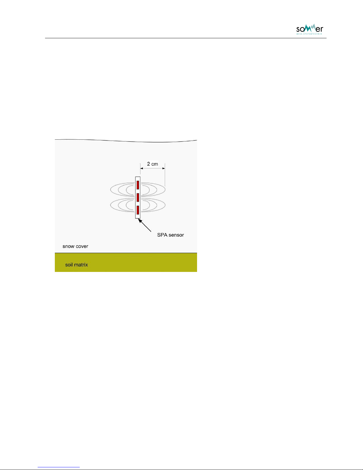
Fig. 1: Principle of measurement of the SPA-sensor
Snow consists of the three components ice, water and air. Referring to different measurement
frequencies, these components show different dielectric constants. Measuring the complex impedance
along a flat ribbon sensor (SPA-sensor) with at least two frequencies allows to estimate the volume
contents of the individual components. These specific volume contents equate the liquid water, ice and air
in the snow pack, which result in the snow density and the snow water equivalent.
Page 5

User Manual SPA Snow Pack Analyser
- 2 -
1.2. Measurement parameters
Snow density
The SPA calculates the snow density of the snow surrounding the SPA-sensor.
Snow water equivalent SWE
The SWE corresponds to the water column in mm resulting from the melting of the complete snow cover
on a defined area. It is calculated from the snow density of sloping sensors with respect to the snow
depth.
Contents of liquid water and ice in snow pack
The volumetric contents of ice and liquid water in the snow are output in %.
Snow depth
The snow depth is measured by an ultra sonic sensor. It is necessary to determine the SWE.
Page 6
User Manual SPA Snow Pack Analyser
- 3 -
2. Hardware
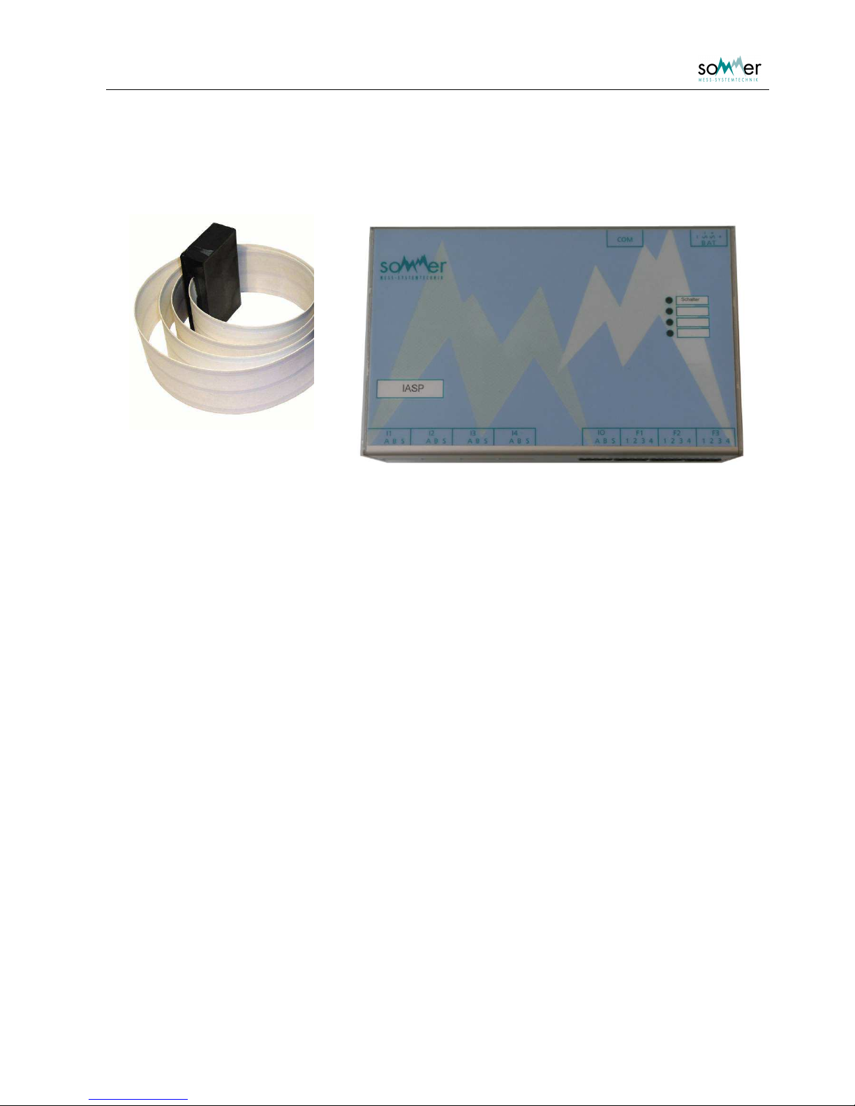
Fig. 2: SPA-sensor
Fig. 3: IASP control unit
2.1. SPA-sensors
The SPA-sensor is a 6 cm wide flat ribbon sensor including three copper wires. The length varies between
3 and 10 m. Its ends are terminated by boxes including mounting rings. The connection cable is led out of
one box.
2.2. Correction length sensor (potentiometer)
The deforming of sloping sensors due to the snow pack can be corrected by measuring the additional
length of the sensor rope at the suspension. The sensor measures the rotation of the suspension roll and
converts the values into length. The correction is automatically included in the calculation.
2.3. Snow depth sensor
The snow depth sensor USH-8 is based on transit-time measurements of an ultrasonic pulse between the
sensor and the snow surface. It is mounted with an extension arm on a mast and is directly connected to
the control unit.
The snow depth is an essential parameter to calculate the snow pack parameters of sloping sensors. On
one hand the length of the sensor in snow is determined and on the other hand the total SWE is
calculated using the actual snow depth.
2.4. Control unit IASP
The control unit IASP performs all measurements, switches between sensors and calculates the snow
parameters with respect to snow depth, length correction and geometric parameters. The data is output
via a RS-232 interface.
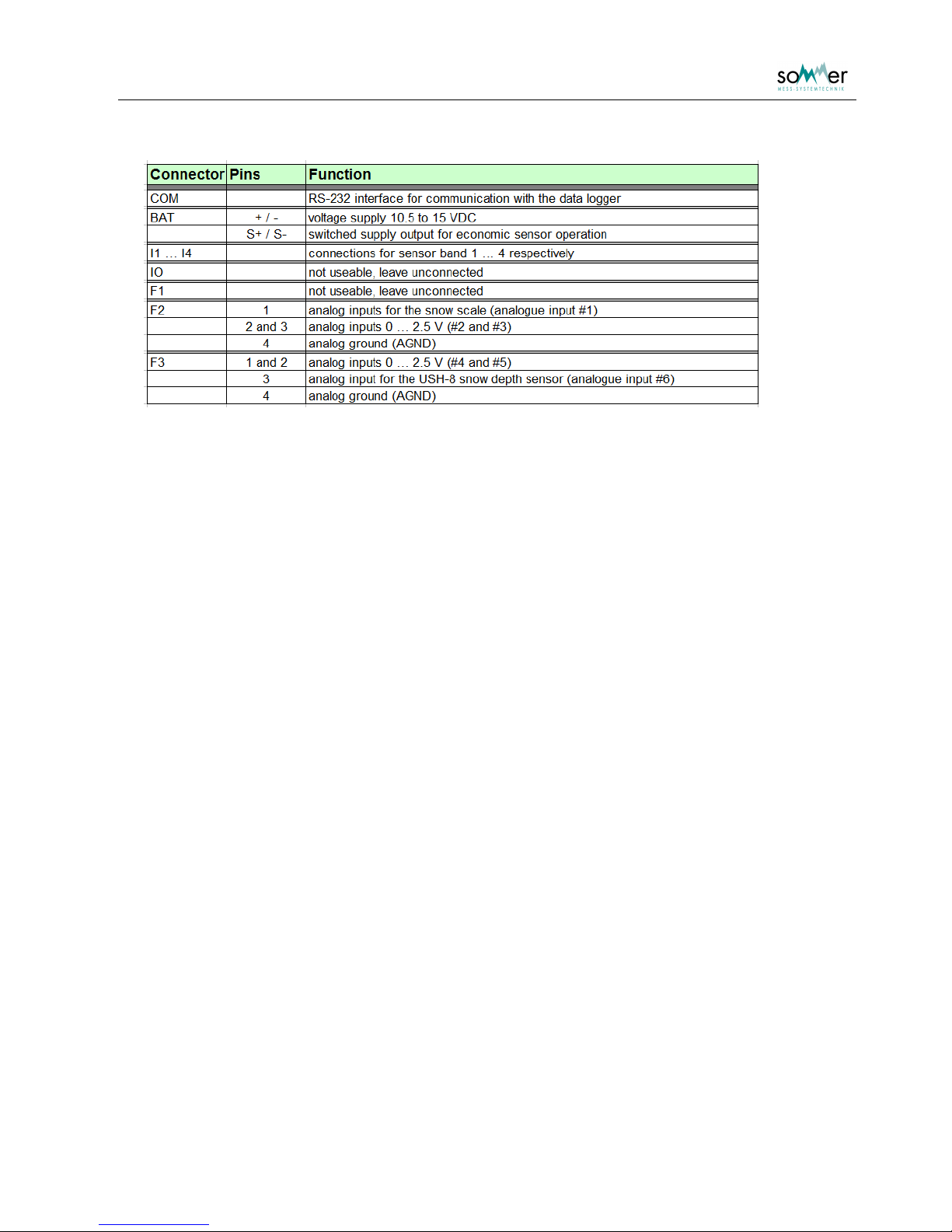
The analogue input F2-1 (#1) is preadjusted for the length correction. The analogue input F3-3 (#6) is
preadjusted for the USH-8 snow depth sensor.
Page 7
User Manual SPA Snow Pack Analyser
- 4 -
Tab. 1: Connector assignment for Fig. 3;
the analogue input F3-3 (#6) is reserved for the USH-8 snow depth sensor
2.5. Framework
The framework enables the installation of one sloping and up to three horizontal sensors and secures a
tight and upright positioning of the sensors. It includes the basement framework, a mast for the installation
of the sloping sensor, the snow depth sensor and the housing and suspension equipment for the SPA
sensors consisting of springs, levers and stretching devices.
Page 8
User Manual SPA Snow Pack Analyser
- 5 -
3. Installation
3.1. Measurement site
A representative measurement site is horizontal and is not located in a basin or on a ridge. It is free of
influences from trees or rocks and is not exposed to intensive winds. An undisturbed accumulation of the
snow pack has to be guaranteed.
3.2. Framework
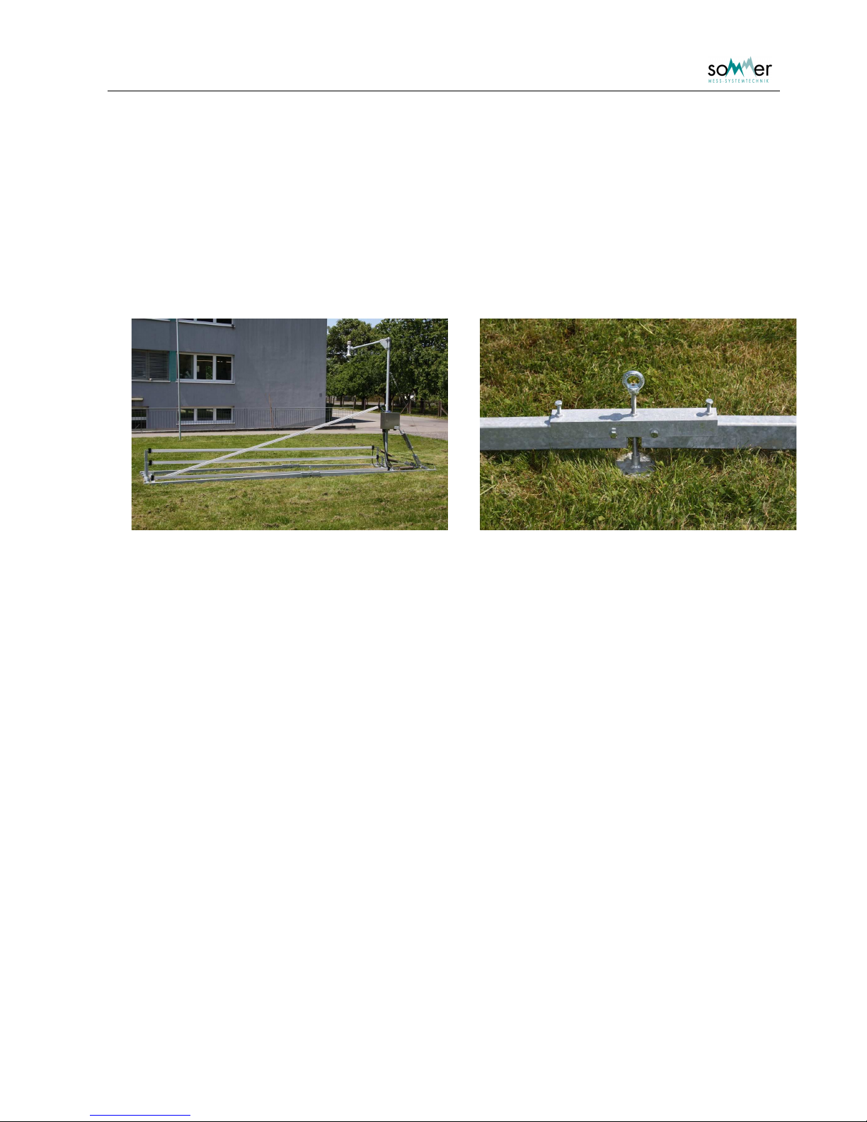
Fig. 4: SPA framework Fig. 5: Connection construction with foot
First the basement framework is placed on the ground. It is delivered separated in two parts each with
about two 3 m long beams connected with cross-beams. The side with the two round cross-beams is for
the installation of the mast and the fixation of the suspension, the side with the rectangle cross-beam is
used for fixing the sensors. The inner L-shaped cross-beam can be located at three position, depending
on the installation height of the sloping sensor of 1.5, 2 or 2.5 m.
The two parts of the framework are connected with a connection construction consisting of a u-profile,
screws and a foot. It is important to install the framework with an initial tension to resist the forces of the
spanned sensors. This is achieved by connecting the two parts of the framework in a small angle, support
it with the foot and fix it with the screws. The height of the foot should be at least 10 cm.
After the installation of the basement the mast is installed on the inner cross-beam. The mast holds the
snow depth sensor, the rolls for the sloping SPA-sensor and the housing for the measurement and
communication devices. It is recommended to install the snow depth sensor before erecting the mast. The
mast is supported with two steel wires to be spanned to the near edges of the basement.
3.3. Snow depth sensor
The snow sensor is an ultra sonic sensors using transit time measurement. It is installed on the top of the
mast using the extension arm. The installation height has to be 1 m above the expected maximal snow
depth. The extension arm should be orientated on one side of the framework to guarantee a snow
measurement free of influences. Ensure that the area of the snow depth measurement is free of
constructions, sensors or cables and that it will be undisturbed during the complete winter season. Use
barrier tapes to prevent accidental entering of the area.
Page 9
User Manual SPA Snow Pack Analyser
- 6 -
3.4. Sloping SPA-sensor
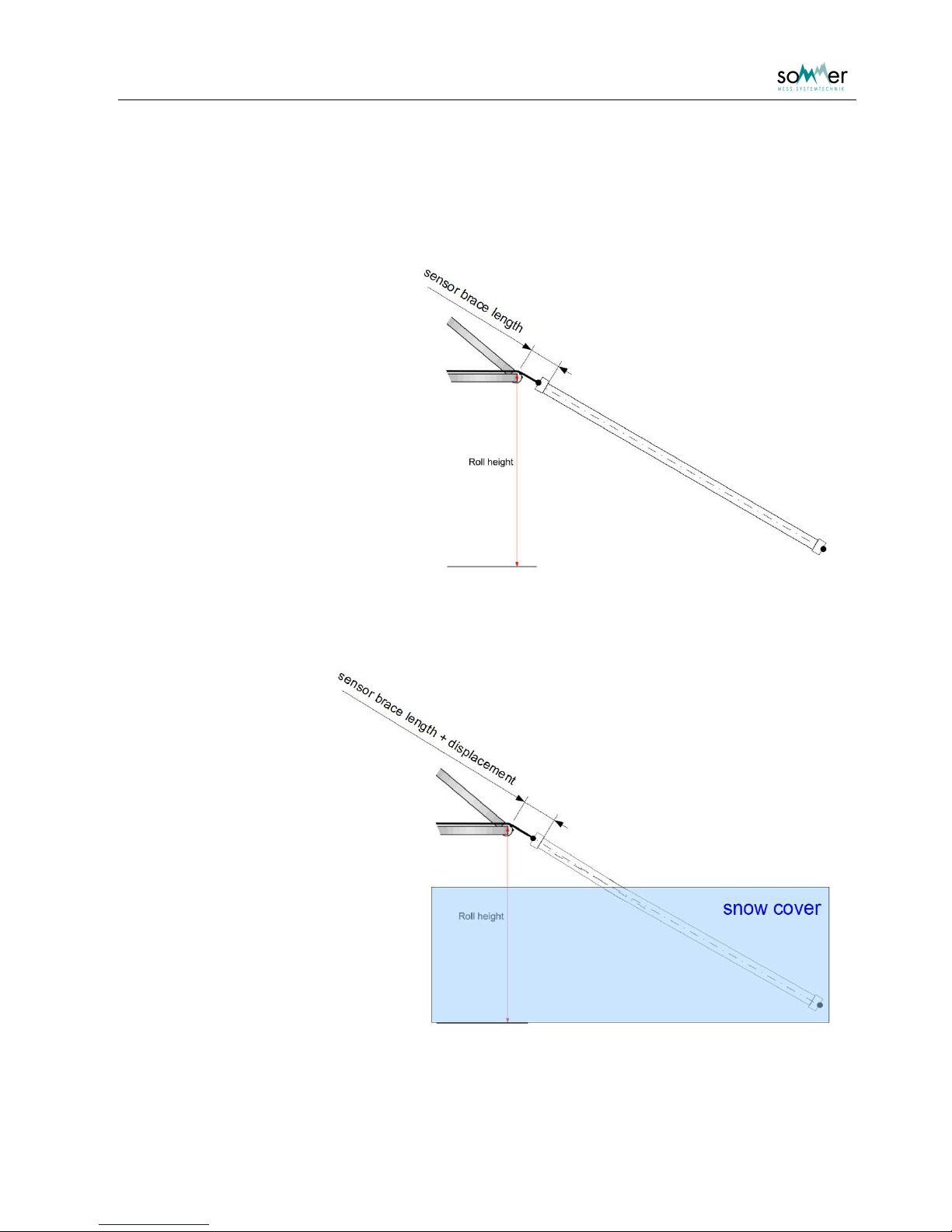
At the skew SPA the bend of the sensor which is also with strong tension not preventable at snow cover
has to be considered.
Without snow cover the sensor
has, caused by the tension, a
straight course.
Fig. 6: Sketch of the sloping sensor, the
tensioner part differs for simplicity from reality
With snow cover it is
possible that the
sensor has at the air /
snow boun-dary a
slight bend.
The sensor is not
stretchable but
nevertheless the bend
leads to an extension
of the fractional part of
the sensor which is
covered by snow.
This increase can be
determined over the
length change in the
sensor brace length.
Fig. 7: Sketch of the sloping band with a snow cover; the slight
bend in the sensor is best noticeable at the symmetry
lines
Page 10
User Manual SPA Snow Pack Analyser
- 7 -
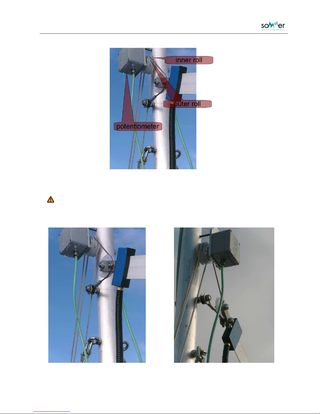
Fig. 8: Upper end of the sloping sensor with the upper part of the tensioner; consider that
the potentiometer is not included at every SPA
Attention:
The inner and outer roll rotate at a length displacement with different extent.
The rotation is only measured at the outer roll. So it is very important that the
ropes are not interchanged during the assembling.
Fig. 9: Upper end of the sloping sensor with the upper part of the tensioner from different
views
Page 11
User Manual SPA Snow Pack Analyser
- 8 -
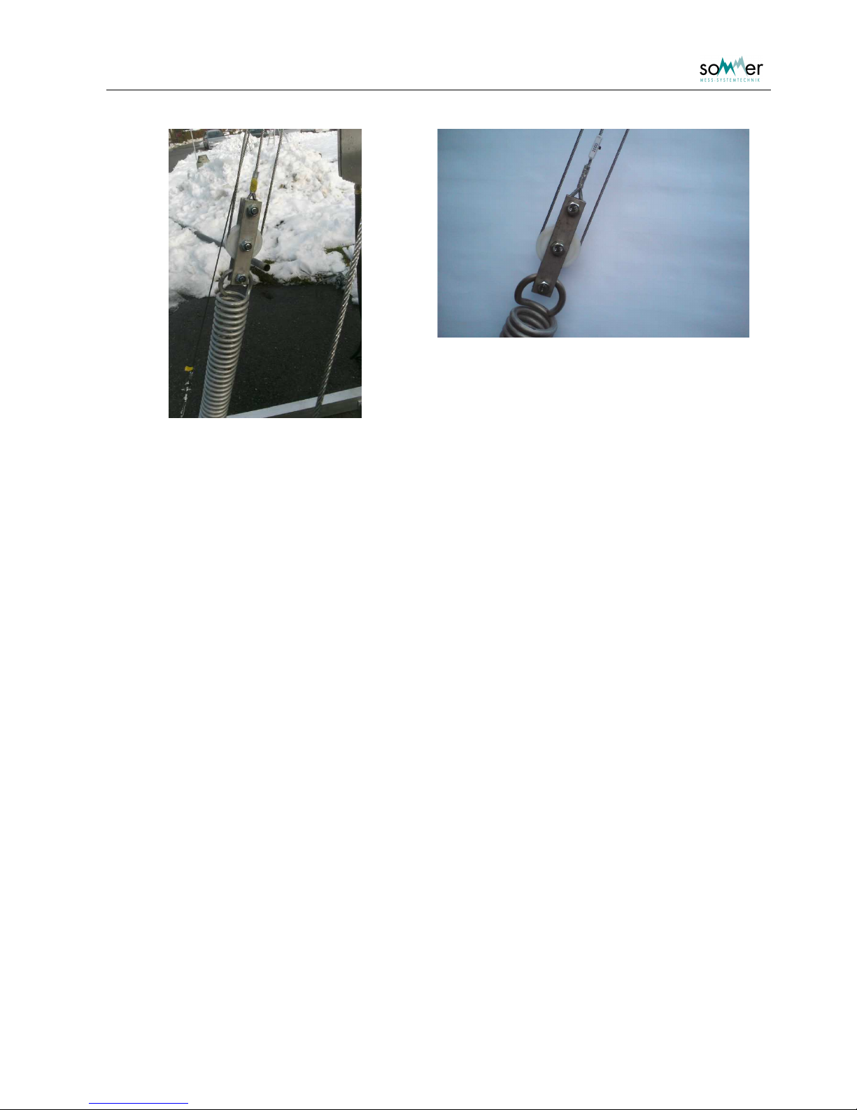
Fig. 10: Suspension at top of the spring with the pulley sytem (overview and detail)
The installation height of the sloping SPA-sensor should be higher than the maximum expected snow
depth. On the mast are three predrilled positions at heights of about 1.5, 2 and 2.5 m. Depending on the
selected height the L-shaped cross-beam is installed at the predefined positions at the far end of the
framework. The higher the sensor is spanned, the nearer the cross-beam is located, where the bottom
end of the SPA-sensor is fixed.
To span the sensor a spring and pulley system is used, that is spanned by a stretching device. The
stretching device is fixed at the near end of the framework and connected to the spring. The small bar with
the lower roll of the pulley system is connected to the opposite side of the spring. The rope of the pulley
system is fixed at the top screw of the bar connected to the spring. Then it is guided to the inner roll fixed
on the mast, back to the roll on the pulley system, up to the outer roll on the mast and through the roll of
the sensor. Finally it is connected to the screw located bellow the rolls on the mast. Then the sensor is
spanned using the stretching device.
3.5. Correction length sensor
If a correction length sensor (potentiometer) is used for the sloping sensor, it is installed at the deflector
roll located on the mast (Fig. 8). The bolt of the sensor has two rotary stop positions. Make sure that the
bolt is in the correct position to react to extensions of the suspension rope.
Page 12
User Manual SPA Snow Pack Analyser
- 9 -
3.6. Horizontal SPA-sensors
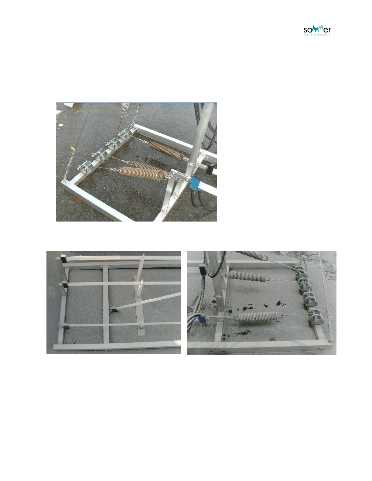
Fig. 11: Spring connection for horizontal sensor
Fig. 12: Far end of framework
Fig. 13: Same as Fig. 11 but from the other side
Page 13

User Manual SPA Snow Pack Analyser
- 10 -
The horizontal SPA-sensors are installed at predefined levels on the installation rack. The far end of the
sensors are connected at the far end of the framework. Then they are connected to the levers located on
the crossbeam of the mast. The stretching devices are fixed to the round cross-beam at the other end of
the framework. The springs are positioned directly at the levers and connected to the wires of the
stretching devices. Afterwards the sensors are spanned using the stretching devices until the spring has
elongated by about 100 mm and the sensor is 5000 mm long. The horizontal sensors are supported with
about 5 forks to ensure an upright and stable position.
3.7. Housing
Mount the housing on the mast and connect the cables of the SPA-sensors, the snow depth sensor and
the correction length sensor at the marked inputs.
3.8. Power supply
The supply voltage of the complete system is 10,5 to 15 VDC.
3.9. Summary
• Install framework with an initial tension.
• Locate snow depth sensor 1 m above the maximal expected snow depth.
• Install the sloping SPA-sensor higher than the maximal expected snow depth.
• Span the sensor using the stretching device.
• Install correction length sensor and set rotary bolt to correct position.
• Install and Span horizontal sensors by elongating the spring by about 100 mm.
Page 14
User Manual SPA Snow Pack Analyser
- 11 -
4. Parameterization
4.1. Connection establishment via terminal
4.1.1. Local communication
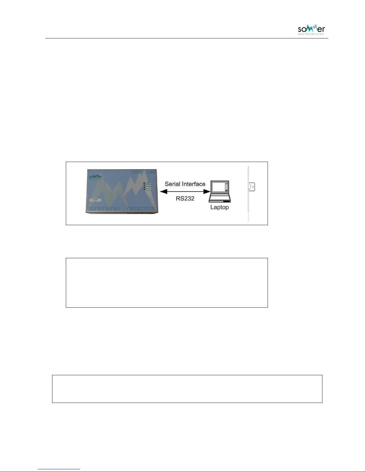
The parameterization of the IASP can be performed by directly connecting the serial interface with a PC or
laptop. Any communication program can be used.
Until Windows XP the terminal program HyperTerminal was included in the Windows operating systems under Start
Programs
Accessories
Communications
HyperTerminal.
The connection cable is a serial data cable with a 1:1 connection (not crossed).
Fig. 14: Connection of the IASP via serial interface
To communicate with the sensor in delivery state the following settings are required:
Baud rate: 9600
Data bits: 8
Parity: none
Stop bits: 1
Flow control: none
Tab. 2: Parameter settings for serial connection
4.1.2. Connection affirmation
If a connection is established and the sensor is switched on, a connection affirmation is sent.
IA-SPA
(c)2006-2012 Sommer GmbH&CoKG
Software version : wdV3.33r01
Page 15
User Manual SPA Snow Pack Analyser
- 12 -
4.2. Main Menu
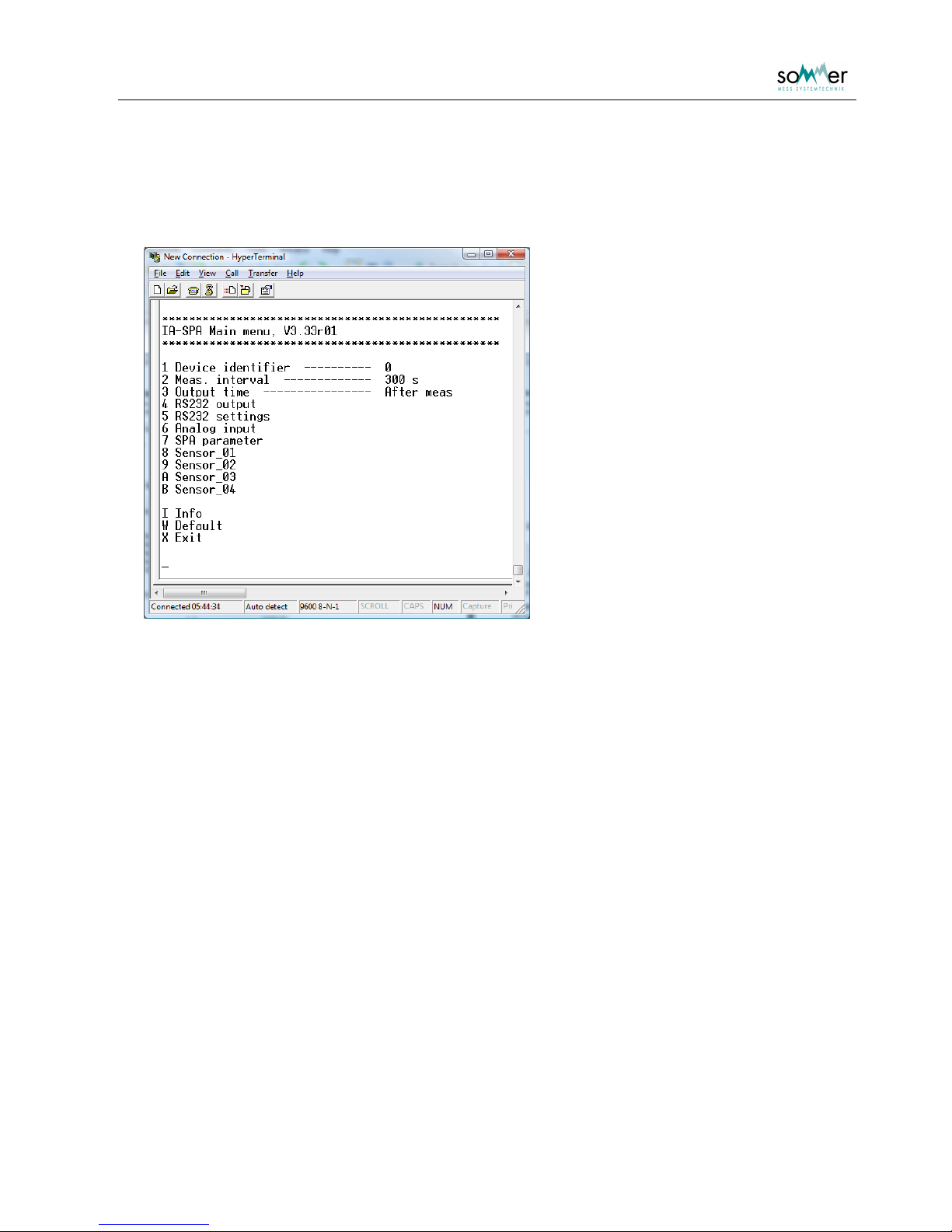
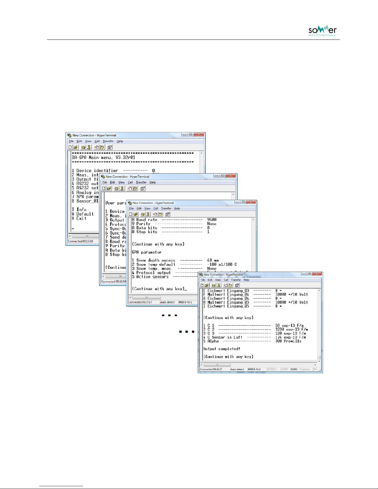
The main menu is opened by quickly entering three question marks ??? in the terminal
program.
Fig. 1: Main menu
The menu items are accessed by entering the menu key display left of the menu item. Either sub menus
are opened or the specific parameter is displayed with the corresponding unit. Changes are verified with
Enter
, editing is aborted with
Esc
. Sub menus are closed with X. The menu is not case sensitive. If the
main menu is closed, the sensor starts the measurement mode and returns the message Run! .
Page 16
User Manual SPA Snow Pack Analyser
- 13 -
5. Necessary parameter adjustments after assembly
5.1. Snow depth
The actual snow depth offset is adjusted in Main menu
Analog input
Snow depth adjustment.
5.2. Displacement offset / Length correction
This step applies only for SPA's which include a potentiometer.
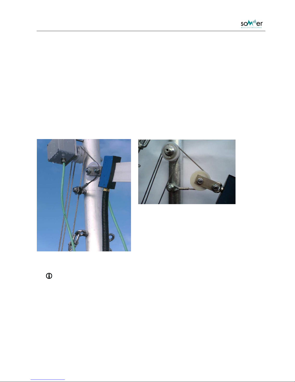
Fig. 15: SPA with potentiometer
Fig. 16: SPA without potentiometer
A sloping SPA-sensor is installed with a spring to ensure a tight spanning and to prevent the
sensor from damages due to compression of the snow pack. This non static installation may
cause changes in the sensor position, that can be corrected by measuring the extension
length of the sensor suspension.
In delivery state the length measurement for SPA-sensor 1 is connected to the analog input 1. This
analogue input (channel) is defined for the SPA-sensor in
Main menu
Sensor_01
Input length corr .
Horizontal sensors are operated without length correction by setting the value of the Input length corr. to
“0”.
Page 17
User Manual SPA Snow Pack Analyser
- 14 -
It is then necessary to adjust the potentiometer which measures the length displacement. Instantly after
the assembling process there is no snow cover on the sensors. Therefor the right offset adjustment is
zero:
Main menu
Analog input
Target value adjustment input_01
0
The actual value is checked with Main menu
8 Sensor_01
6 Input check
5.3. Geometric parameters
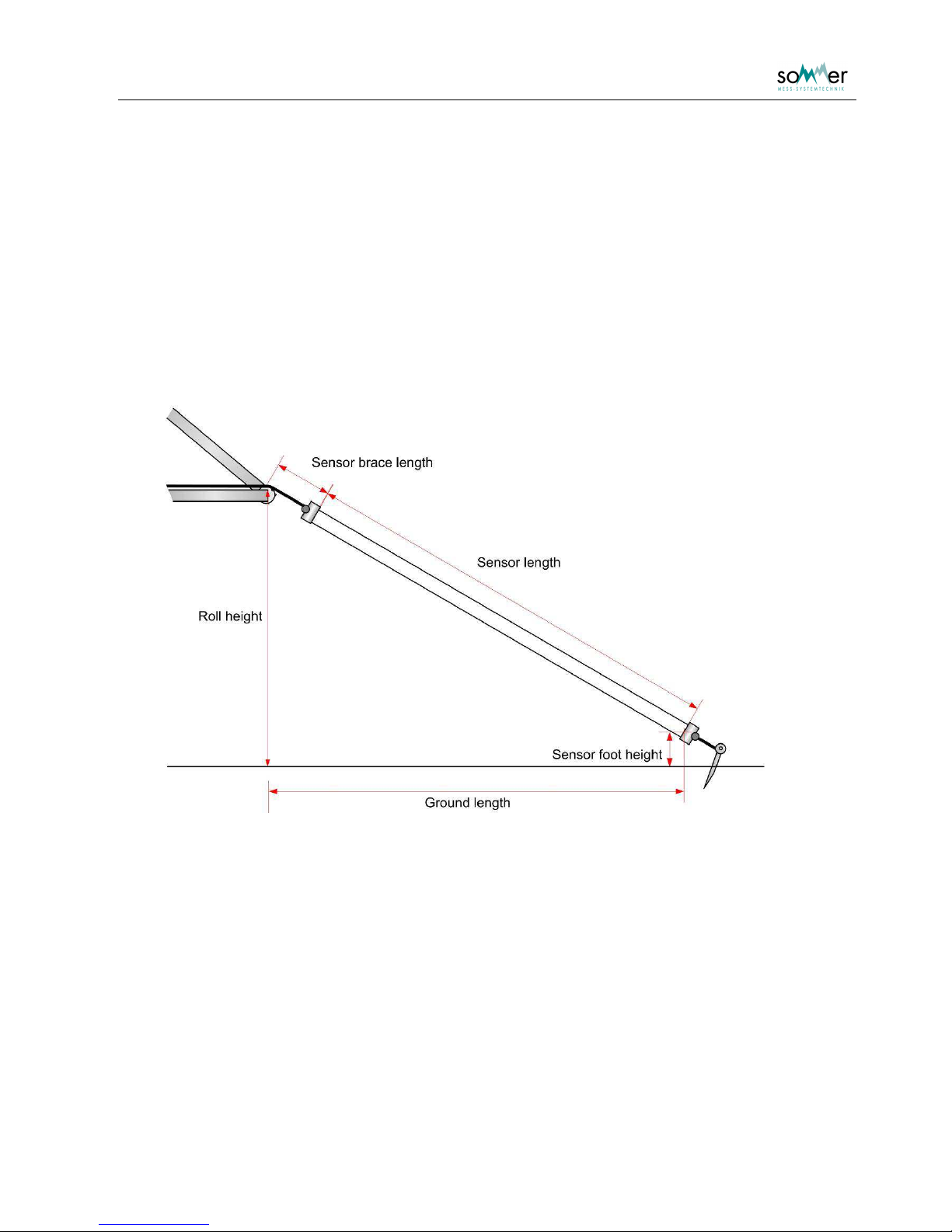
The correct calculation of the snow parameters demands the geometric situation of all included sensors.
Especially for the sloping SPA-sensor these settings are used to determine the length of the sensor in the
snow and to correct a smooth inclination of the measurement site.
Abb. 2: Geometric parameter of SPA-sensor
Numbering of the sensors
The four in different position mounted sensors are indicated with numbers from 1 to 4. For the standard
SPA the assignment is as following:
o diagonal/slope sensor = sensor 1
o horizontal, at the lowest level height (100 mm) sensor = sensor 2
o horizontal, medium level height (300 mm) sensor = sensor 3
o horizontal, at the highest level (500 mm) sensor = sensor 4
Page 18

User Manual SPA Snow Pack Analyser
- 15 -
Adjustment
The following geometric parameters are necessary:
• Sensor length: Length of the sensor from one box to the other.
• Roll height: Plumb line height of the top of the roll and the ground
• Foot height: Plumb line height of the middle of the sensor at the lower box and the ground
• Brace length: Distance between the middle of the roll and the sensor at the upper top box.
• Ground length: Distance on the ground between plumb line of roll and plumb line of sensor foot.
For horizontal sensors the roll height and the foot height have to be equal. The brace length is set to “0”
and the ground length is equal to the sensor length.
The geometric parameters are measured with a measuring tape and should be of about 1 cm accuracy.
The geometric parameters are entered into
Main menu
Sensor_01
Main menu
Sensor_02
Main menu
Sensor_03
Main menu
Sensor_04
5.4. Actual Snow depth
The snow depth measurement offset has to be adjusted in the control unit IASP by entering the actual
value in Main menu
6 Analog input
7 Snow depth adjustment
A test measurement of the snow depth is performed with Main menu
6 Analog input
Snow depth
5.5. Measurement interval
The minimum recommended interval is 5 minutes (= 300 s) ( Main menu
2 Meas. interval )
Attention:
If the interval is adjusted to a lower value eventually temporary problems in
the meausurement process can occur.
The adjusted default interval is 10 minutes.
Page 19

User Manual SPA Snow Pack Analyser
- 16 -
Attention:
Approximately the first 7 minutes after connecting the SPA to the power
supply the measured values are not reliable if the SPA was disconnected for
more than a moment.
During this startup time invalid measurements are indicated with a value of
9999 pF for the measured low frequency capacity and 0000 pF for the
measured high frequency capacity.
example extened MIO protocol output:
I000000000000000000000409;
I0100-999-008-9990000043F;
I020099990000-9999999046B;
The 7 minutes is the time the internal high capacity electrolytic capacitors need to load. These capacitors deliver the
power for the measurement.
Page 20
User Manual SPA Snow Pack Analyser
- 17 -
6. Description of the parameters
1 Device identifier
The device identifier is included in the output protocol to identify the data values. The first output string is
assigned with the device identifier. For every following string the device identifier is increased by 1 (see
chapter 7). It is recommended to set the device identifier to 0.
Value range: 0 to 9999 (default: 0)
Example:
o if Device identifier is adjusted as 0:
I000000000000000000000409;
I0100-999000002510000042A;
I020000100013-862-8860430;
o if Device identifier is adjusted as 3:
I03000000000000000000040C;
I0400-999000002510000042D;
I050000100013-862-8860433;
More details regarding the output strings you can find in chapter 7.
2 Meas. Interval
The measurement interval controls the time for the measurements. For permanent monitoring it is
important, not to set a to short interval. The measurements are performed using a measurement battery. A
to short measurement interval will prevent the battery from charging and the measurement will be invalid.
The recommended interval is 10 minutes (600 s).
Unit: [s]
Value range: 5 to 13980
(default: 600; values greater than 240 are rounded to multiples of 60)
3 Output time
The output of the data is either performed directly after the measurement or the data strings are requested
by a exclamation mark sent via the RS-232 interface.
Page 21
User Manual SPA Snow Pack Analyser
- 18 -
Values:
• After meas = 1 (default) push operation of data output after every
measurement the data is output
• Per ‘!’ over RS232 = 2 pull operation of data output use the '!' for data
output/request
4 RS232 output
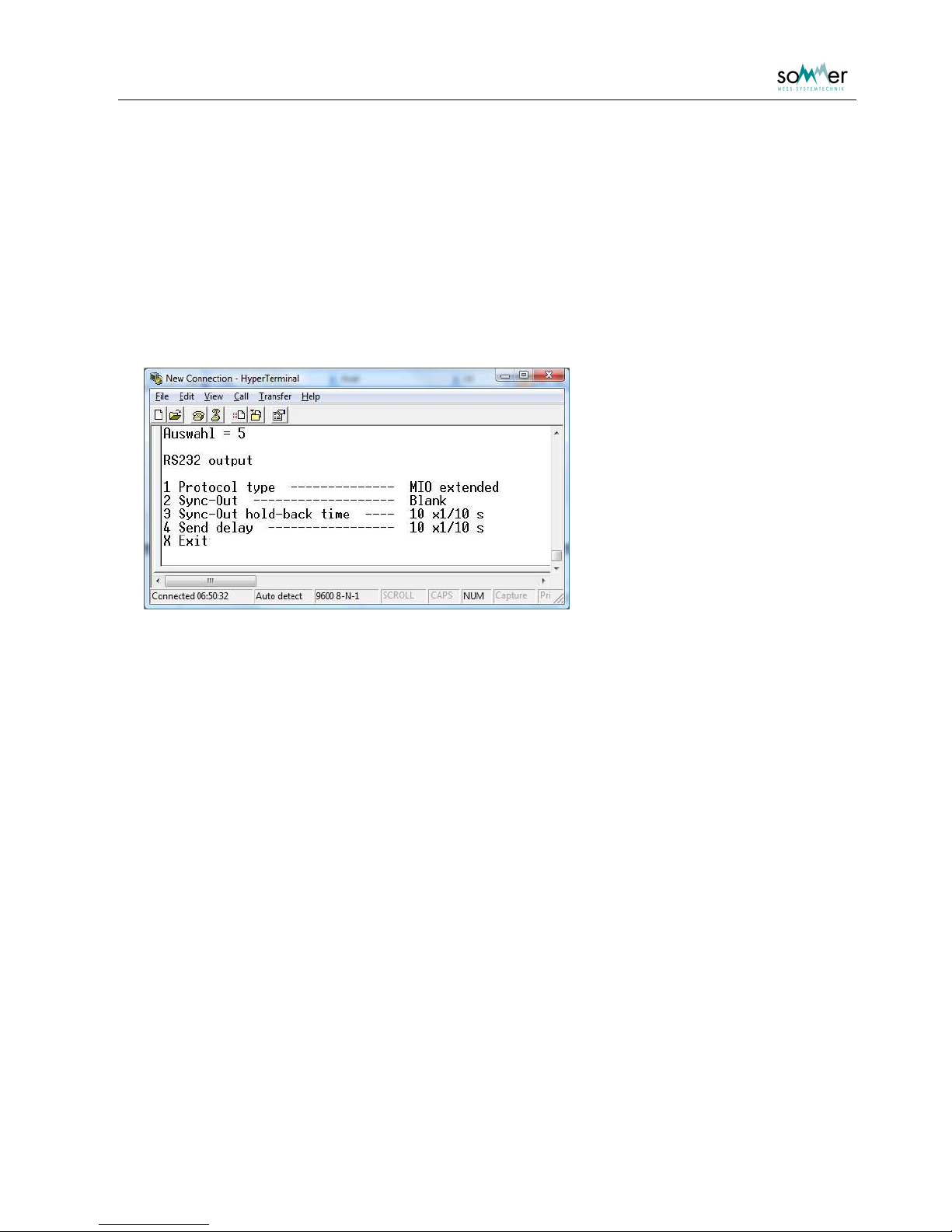
In this submenu the parameter for the output protocol of the RS-232 interface are listed.
Fig. 3: Submenu: RS232 output
1 Protocol type
The protocol type for the data output via the RS-232 is selected. For a description of the protocol see
chapter 7. Basic protocols do not include the capacitances and phases, only the extended protocols do.
• Off = 1
• Standard basic = 2
• MIO basic = 3
• Standard extended = 4
• MIO extended = 5 (default)
2 Sync-Out
The parameter is used for waking up connected data logger. Either a blank is sent prior to the output
strings, or the RTS control line is switched on.
• Off = 1
• RTS method = 2
• Blank = 3 (default)
Page 22
User Manual SPA Snow Pack Analyser
- 19 -
3 Sync-Out hold-back time
The holdback-time defines the time span between the Sync-Out signal (blank or RTS) and the
transmission of the output string.
Unit: [1/10 s]
Value range: 3 to 20 (default: 10)
4 Send delay
The sending delay defines the time span between the strings of the protocol.
Unit: [1/10 s]
Value range: 3 to 100 (default: 10)
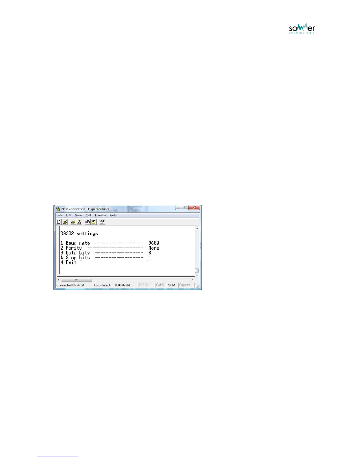
5 RS232 settings
In this submenu the parameters of the RS-232 interface are listed. Changes will cause a reboot of the ISSP. A new parameterization of the interface at the PC may be necessary too.
Fig. 4: Submenu: RS-232 settings
1 Baud rate
The baud rate of the RS-232 interface is selected.
• 1200 Baud = 1
• 2400 Baud = 2
• 4800 Baud = 3
• 9600 Baud = 4 (default)
• 19200 Baud = 5
Page 23

User Manual SPA Snow Pack Analyser
- 20 -
2 Parity
The parity of the RS-232 interface is set.
• none = 1 (default)
• even = 2
• odd = 3
3 Data bits
The number of data bits for the RS-232 interface is set.
• 7 Data bits = 1
• 8 Data bits = 2 (default)
•
4 Stop bits
The number of stop bits for the RS-232 interface is set.
• 1 Stop bit = 1 (default)
• 2 Stop bits = 2
Page 24
User Manual SPA Snow Pack Analyser
- 21 -
6 Analog input
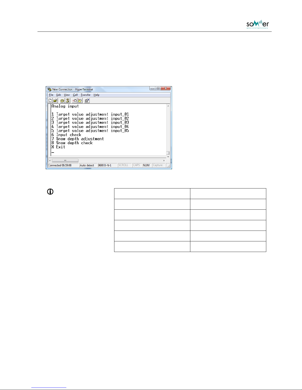
In this menu the measurement values (offsets) of the snow depth and the analog inputs can be adjusted.
Measurements can be performed and the measurement values are displayed.
Fig. 5: Submenu: Analog input
Assignment:
Target value adjustment input_01 displacement sensor
Target value adjustment input_02 for analogue input #2
Target value adjustment input_03 for analogue input #3
Target value adjustment input_04 for analogue input #4
Target value adjustment input_05 for analogue input #5
Snow depth adjustment for analogue input #6
Page 25
User Manual SPA Snow Pack Analyser
- 22 -
1 … 5 Target value adjustment input_0x
A target value for the input can be set. The measurement value is automatically shifted to this value by an
offset.
6 Input check
All inputs are measured and the measurement values are displayed.
7 Snow depth adjustment
A target value for the snow depth is entered. The snow depth is automatically set to this value by an
internal offset.
8 Snow depth check
A measurement of the snow depth is performed and the measured value is displayed.
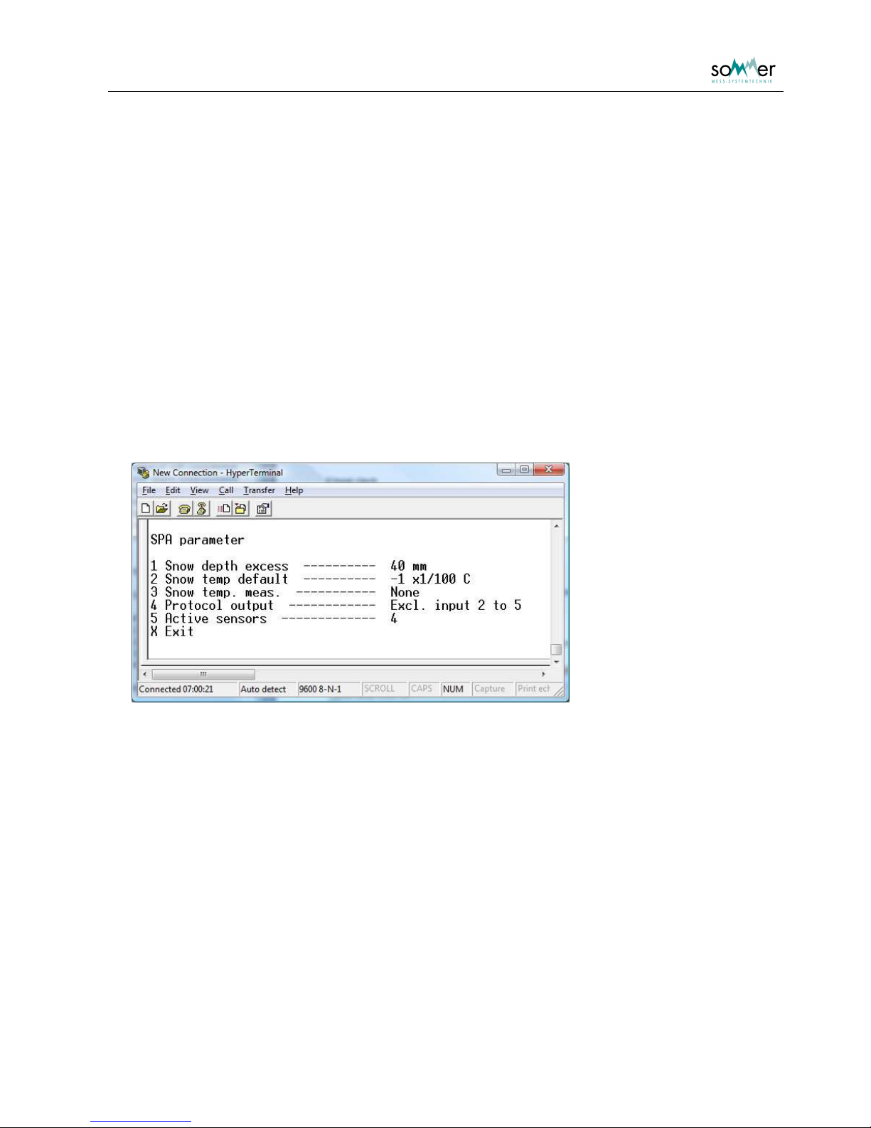
7 SPA parameter
In this menu settings for the SPA measurement and calculation are set.
Fig. 6: Submenu: SPA parameter defaults
1 Snow depth excess
The snow depth excess defines a layer of snow. SPA calculation for any SPA-sensors is only performed, if
the measured snow depth exceeds the foot height of the SPA-sensor by this value.
Unit: [mm]
Value range: 0 to 255 (default: 40)
2 Snow temp default
The SPA calculation is slightly depended on the snow temperature. This value defines the snow
temperature for the calculation, if the temperature is not measured.
Unit: [1/100 °C]
Value range: -5000 to 5000 (default: -100)
Page 26

User Manual SPA Snow Pack Analyser
- 23 -
3 Snow temp. meas.
The parameter defines, if the snow temperature is measured and which input is the snow temperature.
• None = 1 (default)
• Input 1 = 2
• Input 2 = 3
• Input 3 = 4
• Input 4 = 5
• Input 5 = 6
4 Protocol output
The parameter defines, if the values of the inputs 2 to 5 are included in the protocol output.
• Excl. input 2 to 5 = 1 (default)
• Incl. input 2 to 5 = 2
5 Active sensors
The parameter describes the sensors that are measured and output.
• Sensor 1 only = 1
• Sensor 1 and 2 = 2
• Sensor 1 to 3 = 3
• Sensor 1 to 4 = 4 (default)
Page 27
User Manual SPA Snow Pack Analyser
- 24 -
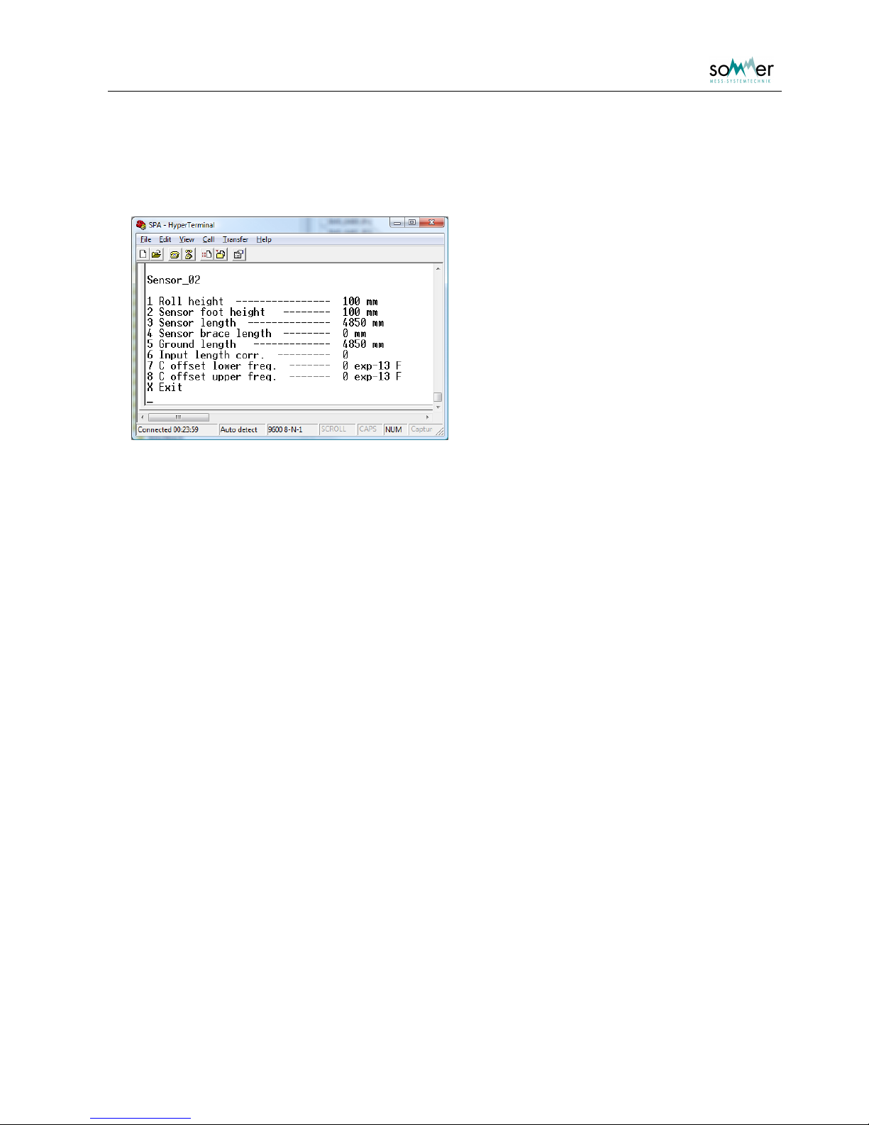
8 Sensor_
For every SPA sensor connected to the IASP the geometric parameters and specific options have to be
set.
Fig. 7: Submenu: defaults for Sensor_02, the Ground length can also be set to zero for horizontal
sensors
1 Roll height
The roll height is the vertical plumb distance from the upper roll of a sloping SPA-sensor to the ground.
For horizontal installed SPA-sensors the roll height and foot height have to be identical.
Unit: [mm]
Value range: 0 to 10000
2 Sensor foot height
The foot height is the vertical distance from the middle wire of the SPA-sensor to the ground. For sloping
sensors it is measured at the end of the sensor. For horizontal installed SPA-sensors the roll height and
foot height have to be identical.
Unit: [mm]
Value range: 0 to 10000
3 Sensor length
The length of the sensor is measured between the two junctions of the sensor and the finishing boxes.
Unit: [mm]
Value range: 0 to 10000 (default: 4850)
4 Sensor brace length
This length is the distance from the upper roll of a sloping SPA-sensor to the junction of sensor and upper
box.
Unit: [mm]
Value range: 0 to 10000
Page 28

User Manual SPA Snow Pack Analyser
- 25 -
5 Ground length
The ground length is the distance at the ground from the plumb lines of the roll and the sensor foot. This
value is only considered at a sensor with skew arrangement.
Unit: [mm]
Value range: 0 to 10000 (default: 4850)
6 Input length corr.
To improve the geometric information of the sensor, a distance sensor can be applied at the top of sloping
SPA-sensor. The parameter defines the input of this distance sensor, that is used for the geometric
correction.
Value range: 0 to 5 (default: 1)
7 C offset lower frequency
The offset value of the SPA sensor. Use this parameter to make a fine adjustment if your system retrieves
e.g. a snow water equivalent unlike zero although the sensor is not covered by snow.
Unit: [exp-13 F]
Value range: 0 to 1000 (default: 0)
8 C offset higher frequency
The measured value of the SPA sensor. Use this parameter to make a fine adjustment if your system
retrieves e.g. a snow water equivalent unlike zero although the sensor is not covered by snow.
Unit: [exp-13 F]
Value range: 0 to 1000 (default: 0))
Page 29

User Manual SPA Snow Pack Analyser
- 26 -
I Info
The software version, the serial number of the device and all settings and measurement parameters are
listed block wise. To proceed any key has to be pressed.
W Default
The complete parameters are set to the default values. All changes are lost.
X Exit
The main menu is closed and the changed settings are accepted. The IASP automatically performs the
defined measurements.
Page 30
User Manual SPA Snow Pack Analyser
- 27 -
7. Data output
The data is output by the RS-232 interface. The protocol is either the standard protocol or the MIO
protocol. Basic protocols do not include the auxiliary values capacitance and phase.
7.1. Protocol values
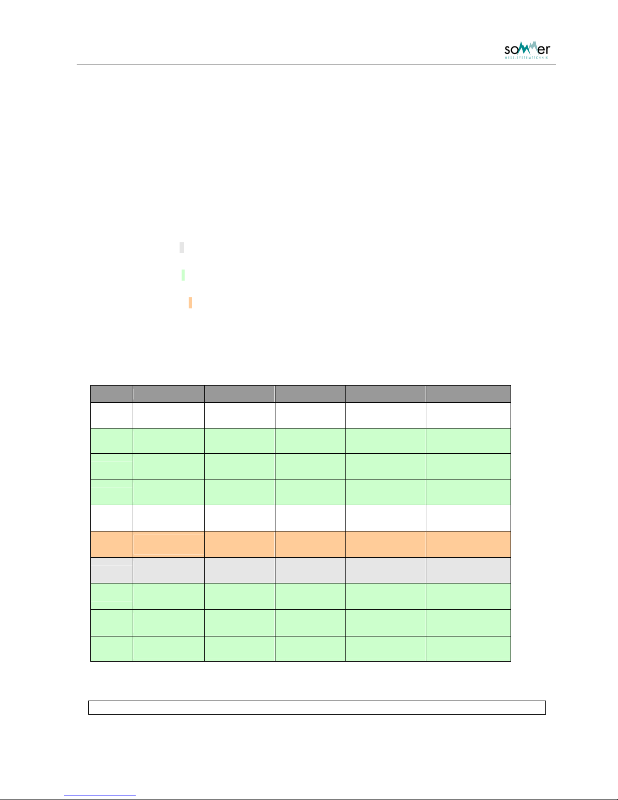
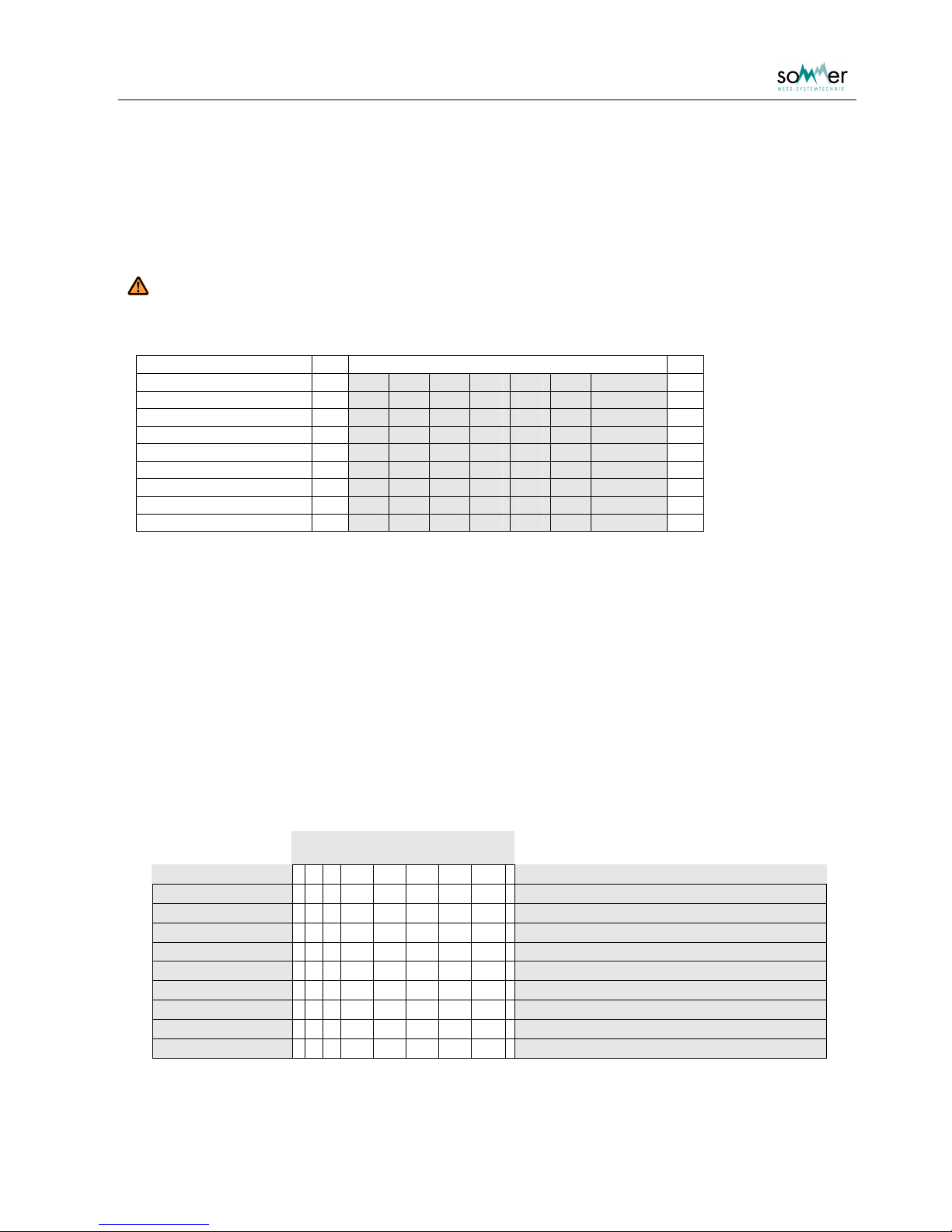
The output values are separated in blocks of four values (Tab. 3). Every block corresponds to a string in
the output protocol and is identified by the string ID. The string ID starts with the Device identifier (see
page 17).
o The white [ ] shaded strings are output in each case.
o The light gray [ ] shaded strings are output if the extended version of the protocol types is used
( RS232 output
Protocol type ).
o The light green [ ] shaded strings are only output if the sensors are activated (not reasonable at the
SPA system) in the menu SPA parameter
Active sensors.
o The light orange [ ] shaded string is only output if in the menu SPA parameter Protocol output
set.
sensor 1 … slope sensor
sensor 2 … horizontal sensor in 100 mm height
sensor 3 … horizontal sensor in 300 mm height
sensor 4 … horizontal sensor in 500 mm height
i String label Values 1 Values 2 Values 3 Values 4
00 Main results
Sensor 1
ice content
Sensor 1
water content
Sensor 1
snow density
Sensor 1
SWE
01
First auxiliary
results
Sensor 2
ice content
Sensor 2
water content
Sensor 2
snow density
Sensor 2
SWE
02
Second
auxiliary results
Sensor 3
ice content
Sensor 3
water content
Sensor 3
snow density
Sensor 3
SWE
03
Third auxiliary
results
Sensor 4:
ice content
Sensor 4
water content
Sensor 4
snow density
Sensor 4
SWE
04
Peripheral
results
Snow depth Analog Input 1 Chip temperature
Length of sensor 1
in snow
05
Aux. peripheral
results
Analog Input 2 Analog Input 3 Analog Input 4 Analog Input 5
06
Sensor 1:
aux. values
Sensor 1
C (low freq.)
Sensor 1
C (high freq.)
Sensor 1
phase (low freq.)
Sensor 1
phase (high freq.)
07
Sensor 2:
aux. values
Sensor 2
C (low freq.)
Sensor 2
C (high freq.)
Sensor 2
phase (low freq.)
Sensor 2
phase (high freq.)
08
Sensor 3:
aux. values
Sensor 3
C (low freq.)
Sensor 3
C (high freq.)
Sensor 3
phase (low freq.)
Sensor 3
phase (high freq.)
09
Sensor 4:
aux. values
Sensor 4
C (low freq.)
Sensor 4
C (high freq.)
Sensor 4
phase (low freq.)
Sensor 4
phase (high freq.)
Tab. 3: Table of MIO values
String ID = Device identifier + i i … two digit index
Page 31
User Manual SPA Snow Pack Analyser
- 28 -
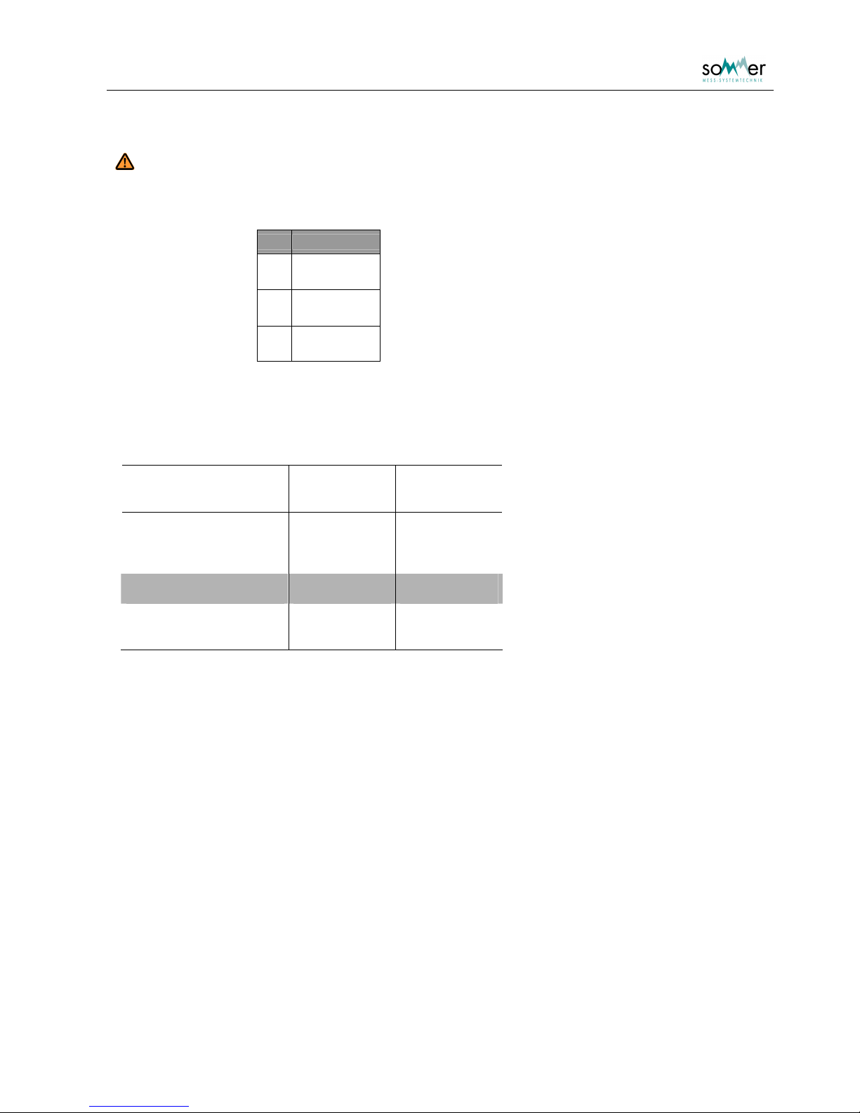
Important:
If strings are not transmitted, then the string indices shift. For example if only the
strings "Main results", "Peripheral results", and "Sensor 1: aux values" are output
(delivery status), then the index assignment would be as following:
i String label
00 Main results
01
Peripheral
results
02
Sensor 1:
aux. values
The units and decimal places of the values 1 – 4 and additional information are:
Value Unit Decimal
Place
Ice content % 1
Water content % 1
Snow density kg/m³ 0
SWE mm 0
Snow depth cm 1
Length corr. (Analog 1) mm 0
Chip temperature °C 1
Capacitance pF 0
Phase ° 1
Tab. 4: Units and decimal places; consider that at the SPA the values Snow depth and Length
corr. do not represent reasonable values
Page 32
User Manual SPA Snow Pack Analyser
- 29 -
7.2. MIO Protocol
MIO transfer consists of multiple ASCII strings containing four data values. A single string starts with the
start ID „I“ followed by the string ID and system number. The four data values are 4 digits long without a
decimal separator.
Attention:
If a value is negative then the minus sign represents the first of the four digits.
The string finishes with a 4-digit checksum in hex format and the end ID
;
Digits
start ID I
string ID 2
placeholder 2
data value 1 4
data value 2 4
data value 3 4
data value 4 4
check sum / CRC-16 4 hex
end ID ;
Tab. 5: MIO string pattern
Example for a an output:
I000009990999099999990409;
I01008000-002024100000428;
I020004880450-894-9420446;
The first string represents according to Tab. 3 the string "Main results". The significance is as follows:
Digits (decimal separator not
output)
cathegory 1 2 2 4 4 4 4 4 1 meaning
start ID
I
string ID
00
placeholder
00
no meaning
ice content
099.9
99.9% (max. value of range)
water content
099.9
99.9% (max. value of range)
snow density
0999
999 kg/m³ (max. value of range)
SWE
9999
9999 mm water column (max. value of range)
Check sum
0409
check sum
end ID
;
example string:
I 00 00 0999 0999 0999 9999 0409 ;
Page 33

User Manual SPA Snow Pack Analyser
- 30 -
The second string represents the "SPA sensor: Peripheral results":
Digits (decimal separator not
output)
cathegory
12 2
4 4 4 4 4 1meaning
start ID
I
string ID
01
placeholder
00
no meaning
snow depth
8000
8000 mm (max. value of range)
analog input 1
-002
dependent on the adjustment in
chip temperature
024.1
24.1°C
length of sensor 1 in
snow
0000
Check sum
0428
check sum
end ID
;
example string:
I 01 00 8000 -002 0241 0000 0428 ;
The third string represents the "SPA sensor: Aux. values"
Digits (decimal separator not
output)
cathegory 1 2 2 4 4 4 4 41meaning
Start ID
I
string ID
02
placeholder
00
no meaning
C (low freq.)
0488
488 pF
C (high freq.)
0450
450 pF
phase (lov freq.)
-89.4
-89.4°
phase (high freq.)
-94.2
-94.2°
Check sum
0446
check sum
end ID
;
example string:
I 02 00 0488 0450 -894 -942 0446 ;
Page 34

User Manual SPA Snow Pack Analyser
- 31 -
7.3. Standard protocol
The standard protocol is the same as the MIO protocol but with following differences:
o All the values within a string are separated with a blank
o There is no start ID
o There is no placeholder
o There is no end ID
example:
output with the Standard extended protocol:
00 0000 0000 0000 0000 0400
01 -999 0006 0229 0000 042C
02 0488 0451 -894 -942 043E
instanteneous after change to the MIO extended protocol:
I000000000000000000000409;
I0100-999000602310000042E;
I020004880451-894-9420447;
Page 35
User Manual SPA Snow Pack Analyser
- 32 -
8. Support
If you need support with the SPA please send us the software version you can see in the main menu.
Please depict also the actual adjustments you can display with pressing the slash key / in the main menu.
Copy this information into a text file and send it to us.
This helps us very much to give you the optimal help.
Page 36

User Manual SPA Snow Pack Analyser
- 33 -
9. Base settings and default values
Menu Parameter description Default value
1. Device identifier 1. Device identifier 0
2. Meas. interval 2. Meas. interval 600
3. Output time 3. Output time After meas
4. RS232 output 4.1 Protocol type MIO extended
4.2 Sync-Out Blank
4.3 Sync-Out hold-back time 10
4.4 Send delay 10
5. RS232 settings 5.1 Baud rate 9600
5.2 Parity None
5.3 Data bits 8
5.4 Stop bits 1
7. SPA parameter 7.1 Snow depth excess 40 mm
7.2 Snow temp default -100 x1/100 C
7.3 Snow temp. meas. None
7.4 Protocol output Excl. input 2 to 5
7.5 Active sensors Sensor 4
8. Sensor_01 8.1 Roll height 2000 mm
8.2 Sensor foot height 80 mm
8.3 Sensor length 4850 mm
8.4 Sensor brace length 150 mm
8.5 Ground length
8.6 Input length corr. 1
8.7 C offset lower frequency 0 exp-13 F
8.8 C offset higher frequency 0 exp-13 F
9. Sensor_02 9.1 Roll height 100 mm
9.2 Sensor foot height 100 mm
9.3 Sensor length 4850 mm
9.4 Sensor brace length 0 mm
9.5 Ground length 0 mm
9.6 Input length corr. 0
9.7 C offset lower frequency 0 exp-13 F
9.8 C offset higher frequency 0 exp-13 F
A. Sensor_03 A.1 Roll height 300 mm
A.2 Sensor foot height 300 mm
Page 37

User Manual SPA Snow Pack Analyser
- 34 -
A.3 Sensor length 4850 mm
A.4 Sensor brace length 0 mm
A.5 Ground length 0 mm
A.6 Input length corr. 0
A.7 C offset lower frequency 0 exp-13 F
A.8 C offset higher frequency 0 exp-13 F
B. Sensor_04 B.1 Roll height 500 mm
B.2 Sensor foot height 500 mm
B.3 Sensor length 4850 mm
B.4 Sensor brace length 0 mm
B.5 Ground length 0 mm
B.6 Input length corr. 0
B.7 C offset lower frequency 844 exp-13 F
B.8 C offset higher frequency 844 exp-13 F
Page 38

User Manual SPA Snow Pack Analyser
- 35 -
10. Technical data
Technical changes and errors excepted
IASP = SPA analyzer module
Inputs
4 x SPA sensors
1 x Snow depth: 4..20 mA (USH-8)
1 x SPA sensor length
Output
1 x RS-232: 1200..9600 Baud
ASCII protocol
Power supply
Supply voltage: 10,5 to 15 VDC
Reverse voltage protection
Overvoltage protection
Energy consumption
Active: 50 mA
at 5 s measurement time per SPA sensor
Sleep: < 2 mA
Measurement range
SWE: 0..9999 mm water column
Snow density: 0..999 kg/m³
Ice and water content: 0,0..99,9 %
Snow depth: 0..8 m (see USH-8 manual)
Area of application
Operating temperature: -35 °C to +60 °C
Housing
Material: Anodized aluminum
Dimensions: 70 x 100 x 55 mm (L x H x W)
Installation: Mounting for top hat rail
Protection type
IP 55
Page 39

User Manual SPA Snow Pack Analyser
- 36 -
SPA Sensor
Coating
Material: PVC
Ultraviolet resistant
Conductors
3 copper wires
Connection Cable
Length: 4000 mm
Connector: Watertight sealed
Dimension
Width: 60 mm
Length: 4850 mm
SPA Framework
Material
Steel
Dimension
Length: 6360 mm
Width: 1100 mm
Height (mast): 3000 mm (standard)
 Loading...