

Page 1
Back to Menu page
The XP504 beam is an
intermediate sized beam designed to replace conventional 3
- and 4
-
element
antennas. Although
the boom length is a modest 4.4 metres, superb performance is obtained through the TOTAL elimination of L/C traps.
the XP504.
meters at a later date.
core device made
without heating and
the beam is rated above maximum legal power
– regardless of mode or
band.
craftsmanship that
ensures that this Sommer antenna will provide many years of
maintenance
-
free performance.
Dimensions
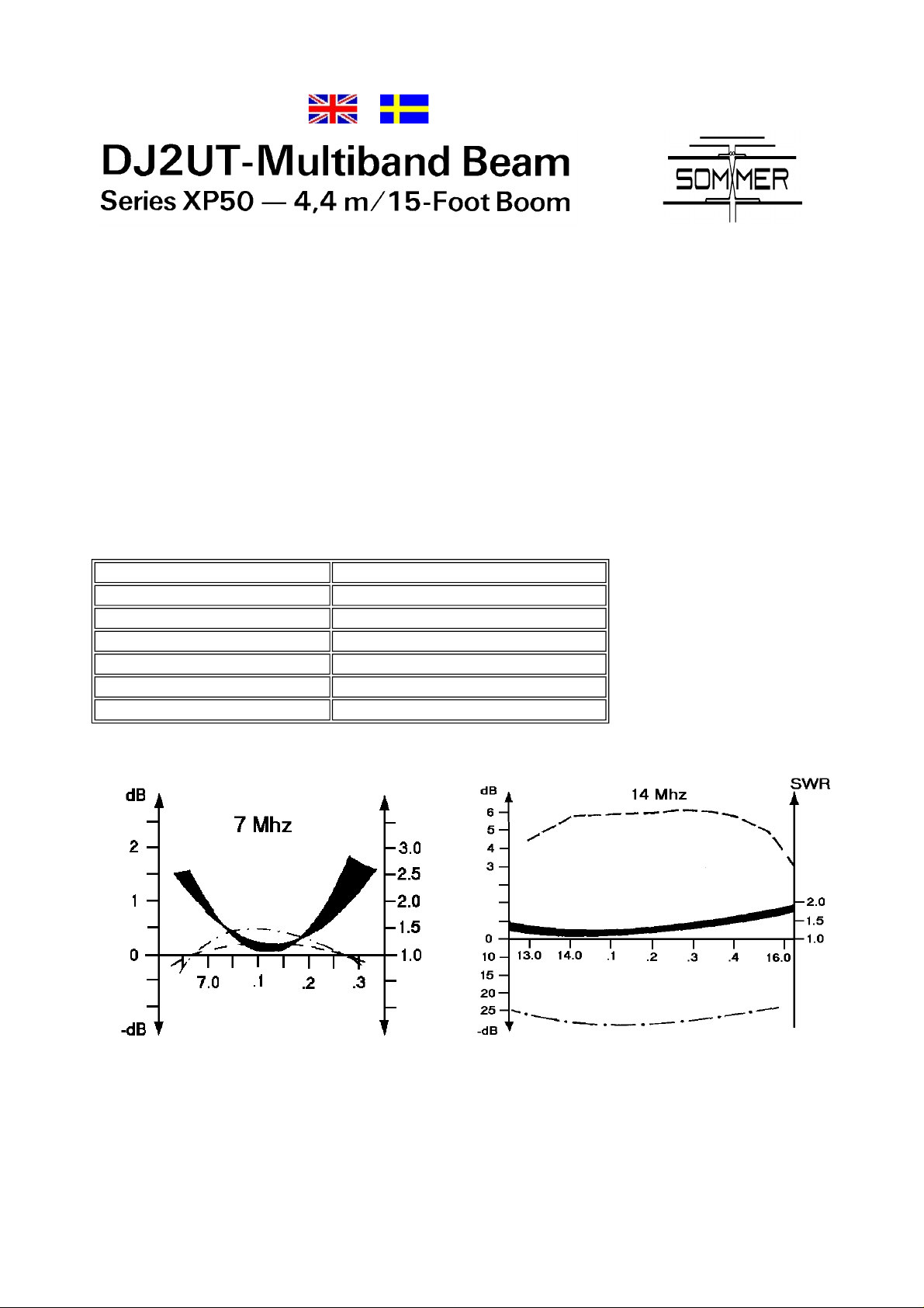
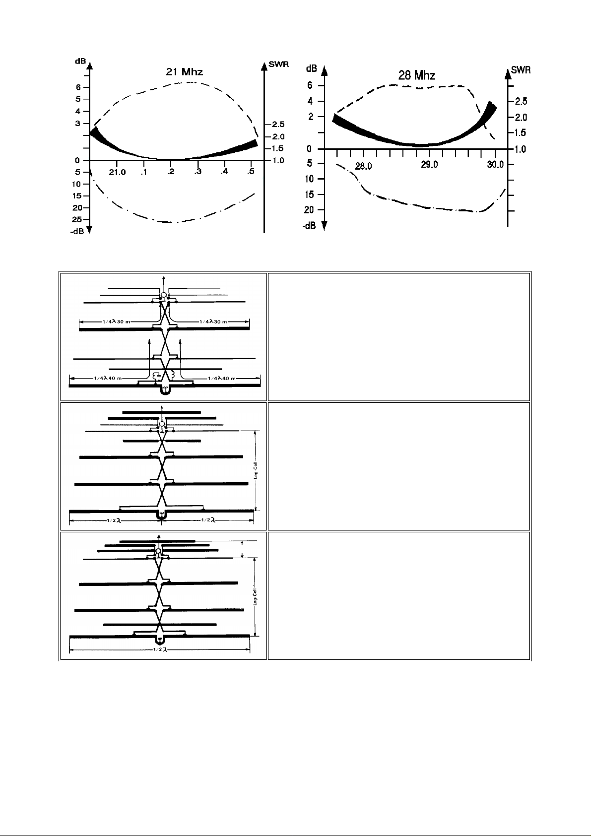
Gain and
SWR
Former trapped-antenna owners immediately notice increased signal reports, broader gain and SWR bandwidths, and
f/b ratios that are good across the entire band – not just over one small sector. The performance graphs below illustrate
The XP504 covers 10, 15, 20 and 40 meters. A simple, inexpensive conversion kit allows you to add 12, 17 and 30
To maintain high performance, the DJ2UT antenna is fed with a model UT-2000 balun. This is an airfrom high-voltage, Teflon dialectric coaxial cable. With no ferrite core to saturate, this balun will handle 2 kW output
The XP504 antenna is built to very high standards of strength. Aircraft-quality aluminum tubing is used throughout,
and all hardware is made of stainless steel. High-quality materials, combined with precision German
Longest element 11.2 m
Boom length 4.4 m
Turning radius 6.5 m
Max mast diameter 52 mm
Wind loading 72 sq dm
Net weight 25 kg
Wind survival Greater than 128 km/h
Page 2
Working principle
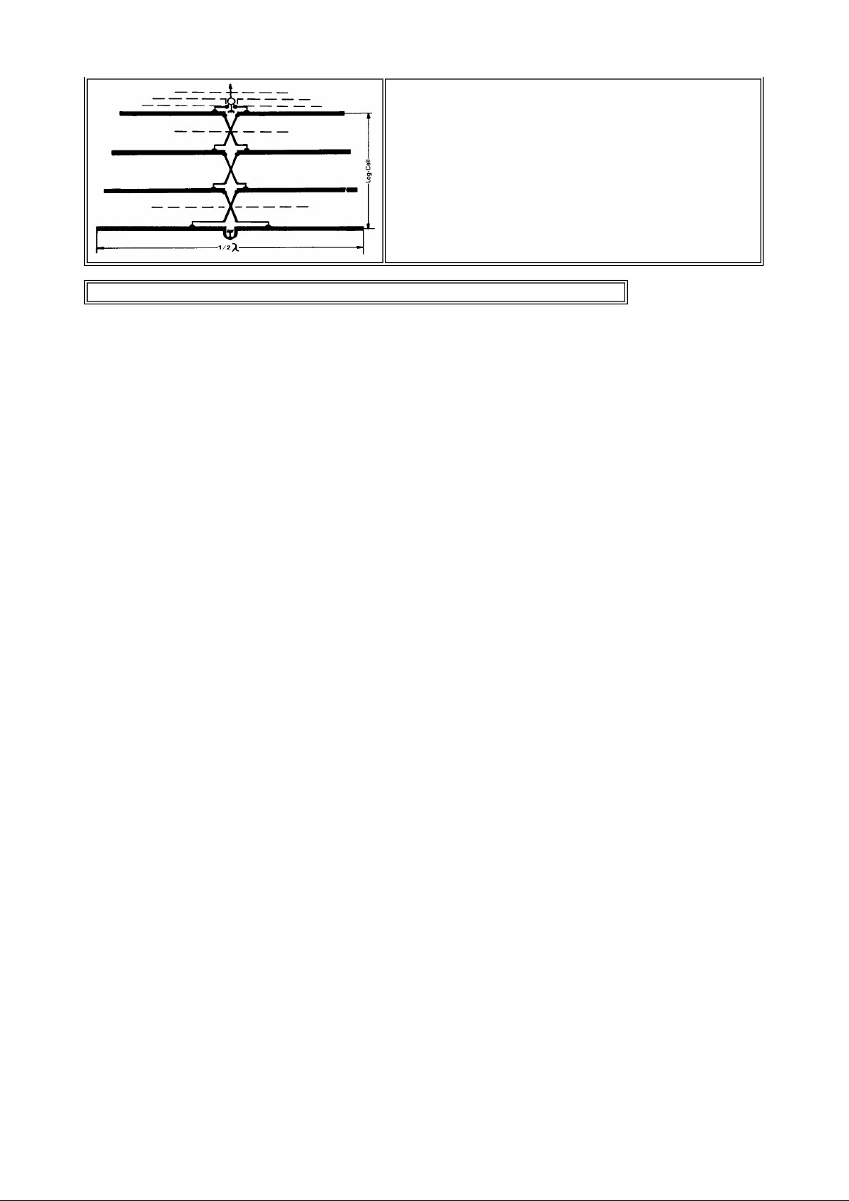
20 m
On this band the DJ2UT system is a full sized beam utilizing 1/2-wave
elements without traps. The primary difference is that all elements are
driven via a phasing line – in a fashion similar to the log periodic. This
technique provides "monoband" gain or better without the narrow
bandwidth commonly associated with such antennas. As on alI bands,
the compromise between forward gain and f/b ratio has been optimized
for amateur use through actual on-the-air testing – and not random
selection.
15 m
Because the 20-m elements are approximately 5/8-wave long on this
band, the resulting high feed point impedance must be compensated
for. Instead of resorting to "power-hungry" L/C traps DJ2UT utilizes the
capacitance found in the phasing line, in combination with another
unique approach. Clustered about the feed point are 3 in close
proximity to each other. This combination of parasitic and driven
elements simply and effectively brings the system impedance down to
the desired 50 Ohms. In addition, a special means of feeding the
elements reduces the unwanted side-lobe radiation common to 5/8wave systems.
10 m
Since the primary elements of this design are 1/2-wavelength on 20 m,
they are approximately a full wavelength on 10 m. In the DJ2UT
system, they are fed via the phasing line as "split" 1/2-wavelength
elements in a collinear fashion. This configuration also presents a high
feed point impedance. As on 15 m, this high value is reduced to 50
Ohms by the influence of 3 or 4 elements in close proximity.
Page 3
40 m
By ignoring all elements but the longest (found at the rear of the
boom), we may consider the DJ2UT antenna a simple dipole with a
transmission line attached. Since this element, or dipole, is only 11,6 m
(approx.) long, it is too short to be resonant on 40 m and presents a
capacitive reactance in this band. Compensation on 40-m is achieved
with a coil and/or coaxial capacitor. Since this network is not in series
with the antenna and only serve to cancel the "blind" reactive
components, the problems of L/C trap loading are again avoided. On
40 m the antenna has the same bi-directional characteristics as a 1/2wave dipole.
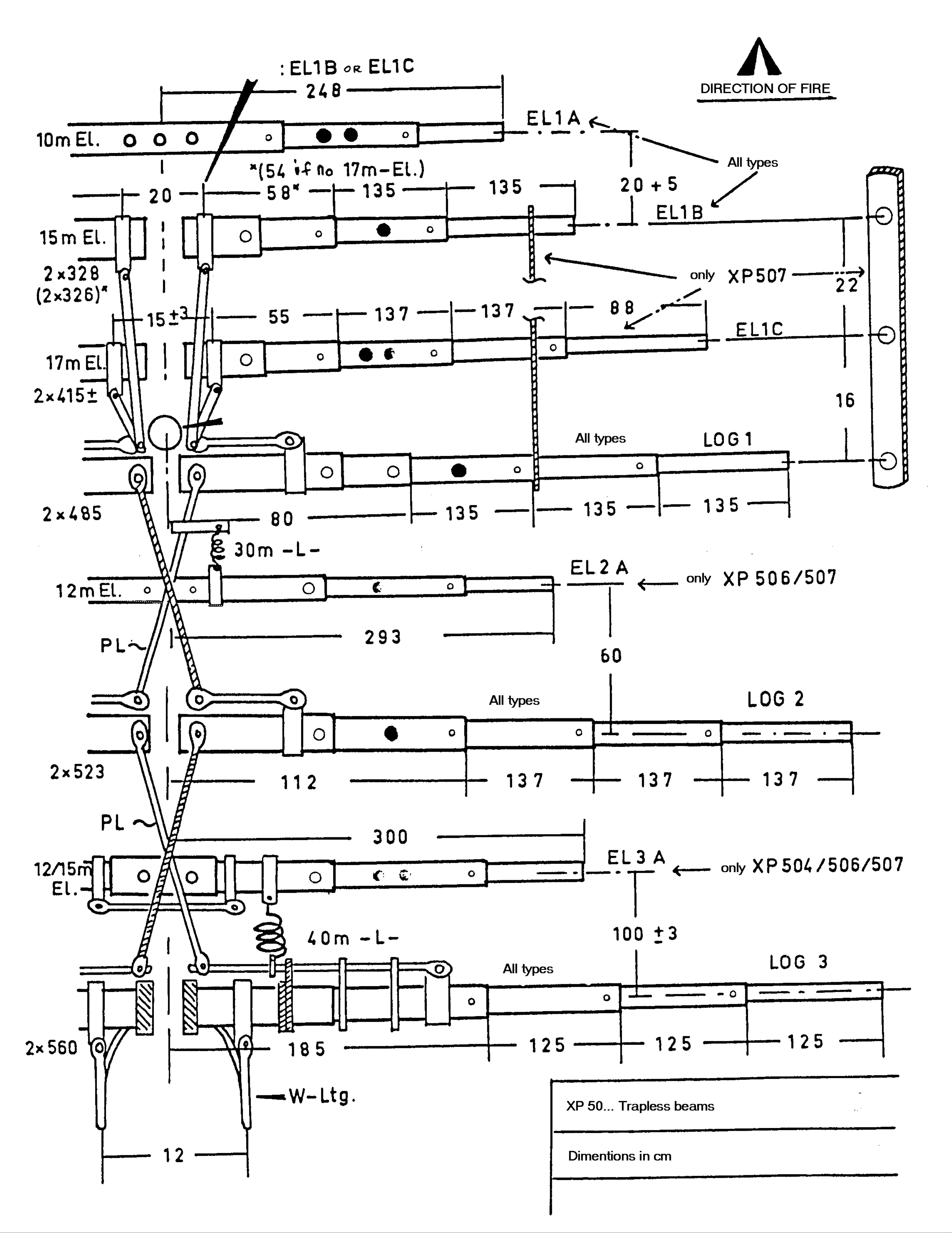
Detailed drawing with dimensions (Note! Just over 100Kb but lots of info)
Page 4
 Loading...