

Page 1
www.somfy.com
ilmo2 50 WT
NOTICE
FR
ANLEITUNG
DE
INSTRUCTIONS
EN
ИНСТРУКЦИЯ
RU
ÚTMUTATÓ
HU
INSTRUKCJA
PL
NÁVOD
CS
MANUAL
RO
UPUTSTVO
SR
UPUTSTVA
HR
ROKASGRĀMATA
LV
Ref.5125862A
l6Yg$m
Page 2

Page 3

FR
NOTICE ORIGINALE
Cette notice s’applique à toutes les motorisations ilmo 50 WT dont les déclinaisons sont disponibles au
catalogue en vigueur.
SOMMAIRE
1. Informations préalables 1
1. 1. Domaine d’application 1
1. 2. Responsabilité 1
2. Installation 2
2. 1. Montage 2
2. 2. Câblage 3
2. 3. Mise en service 4
2. 4. Astuces et conseils d’installation 5
L’i lm o 50 W T es t u n mo te ur s an s rég la ge : u n s im pl e br anc he me nt p er me t son u ti li sa ti on .
L’i lm o 50 W T ap pre nd s es fi ns de c ou rs e au to mat iq ue me nt .
L’i lm o 50 W T s e mo nte i nd iffér em me nt à dro it e o u à g au ch e. Il s e c om ma nd e à p ar tir d ’u n p oi nt de c om man de
de type inverseur à position fixe ou momentanée.
L’i lm o 50 W T es t é qu ip é :
- d’une protection contre les obstacles pour protéger le tablier du volet roulant à la descente.
- d’une protection contre le gel pour protéger le tablier du volet roulant à la montée.
1. INFORMATIONS PRÉALABLES
1. 1. DOMAINE D’APPLICATION
La motorisation ilmo 50 est conçue pour motoriser tous types de volets roulants équipés de butées
et de liens rigides.
L’i ns ta ll at eu r, p ro fe ss ion ne l de l a m ot or is at io n e t de l ’au to ma ti sa ti on d e l ’h ab it at do it s ’as su rer q ue
l’installation du produit motorisé une fois installé respecte les normes en vigueur dans le pays de mise
en service
comme notamment la norme sur les volets roulant EN13659.
3. Utilisation et maintenance 6
3. 1. Montée et descente du volet roulant 6
3. 2. Détection des obstacles 6
3. 3. Protection contre le gel 6
4. Astuces et conseils d’utilisation 7
5. Données techniques 7
1. 2. RESPONSABILITÉ
Avant d’installer et d’utiliser la motorisation, lire attentivement cette notice. Outre les instructions
décrites dans cette notice, respecter également les consignes détaillées dans le document joint
Consignes de sécurité.
La motorisation doit être installée par un professionnel de la motorisation et de l’automatisation de
l’habitat, conformément aux instructions de Somfy et à la réglementation applicable dans le pays de
mise en service.
Tou te ut ili sation de la mot orisa tion hor s du d omain e d’ap plica tion déc rit ci-d essus es t int erdi te. El le
exclurait, comme tout irrespect des instructions figurant dans cette notice et dans le document joint
Consignes de sécurité, toute responsabilité et garantie de Somfy.
L’i ns ta ll at eu r doi t in fo rm er se s cl ie nt s d es c on di ti ons d ’u ti li sa tio n et d e m ai nt en an ce d e l a mo to ri sat io n
et doit leur transmettre les instructions d’utilisation et de maintenance, ainsi que le document joint
Consignes de sécurité, après l’installation de la motorisation. Toute opération de Service Après-Vente
sur la motorisation nécessite l’intervention d’un professionnel de la motorisation et de l’automatisation
de l’habitat.
Si un doute apparaît lors de l’installation de la motorisation ou pour obtenir des informations
complémentaires, consulter un interlocuteur Somfy ou aller sur le site www.somfy.com.
Avertissement Sécurité!
Copyright © 2015 Somfy SAS. All rights reserved.
Attention! Information
1
Images non contractuelles
1
Page 4
FR
2. INSTALLATION
Consignes à suivre impérativement par le prof essio nnel de l a motori sation e t de l’aut omat isati on
1
de l’habitat réalisant l’installation de la motorisation.
Ne jamais laisser tomber, choquer, percer, immerger la motorisation.
1
Installer un point de commande individuel pour chaque motorisation.
1
Ne jamais connecter 2 points de commande sur un même moteur.
1
Vérifier la compatibilité en cas d’utilisation de ce moteur avec un système bus
1
(ex: système «
2. 1. MONTAGE
Contrôler la robustesse du volet roulant et de ses équipements.
1
S ’ a s s u r e r q u e l a m o t o r i s a t i o n u t i l i s é e e s t a d a p t é e à l a t a i l l e d u v o l e t r o u l a n t a fi n d e n e p a s r i s q u e r
1
d’endommager le volet roulant et/ou le produit Somfy.
P o u r o b t e n i r d e s r e n s e i g n e m e n t s s u r l a c o m p a t i b i l i t é d e l a m o t o r i s a t i o n a u v o l e t r o u l a n t e t a u x
accessoires, s’adresser au fabricant de volet roulant ou à Somfy.
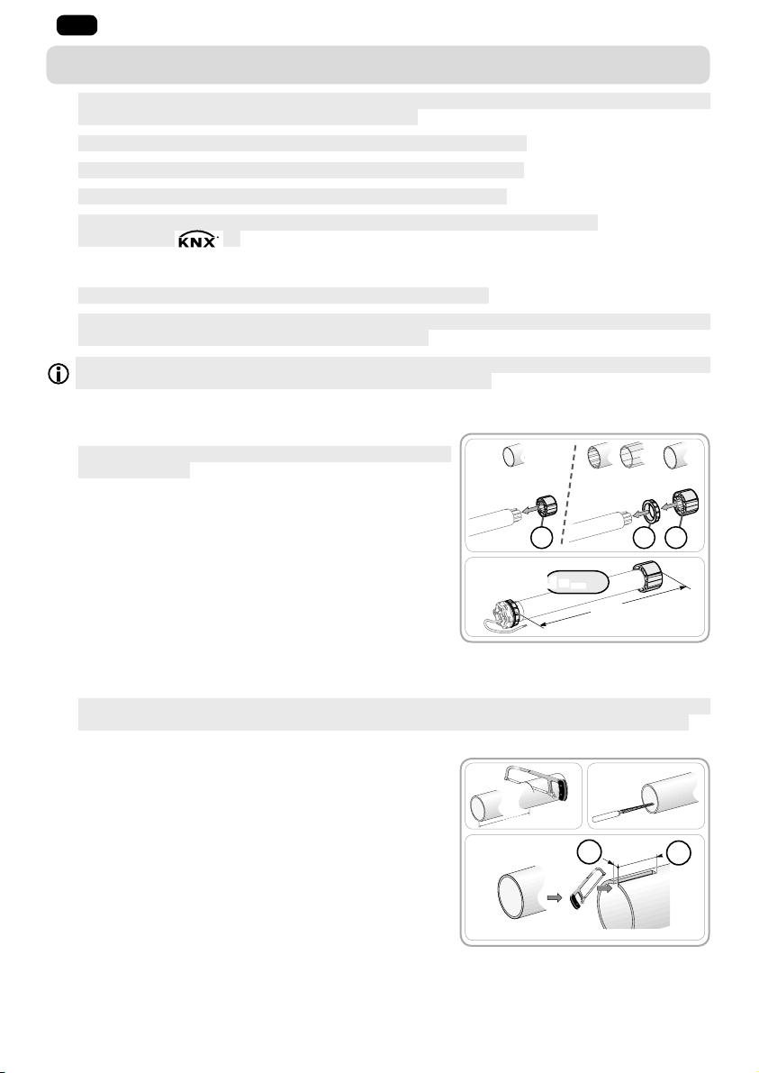
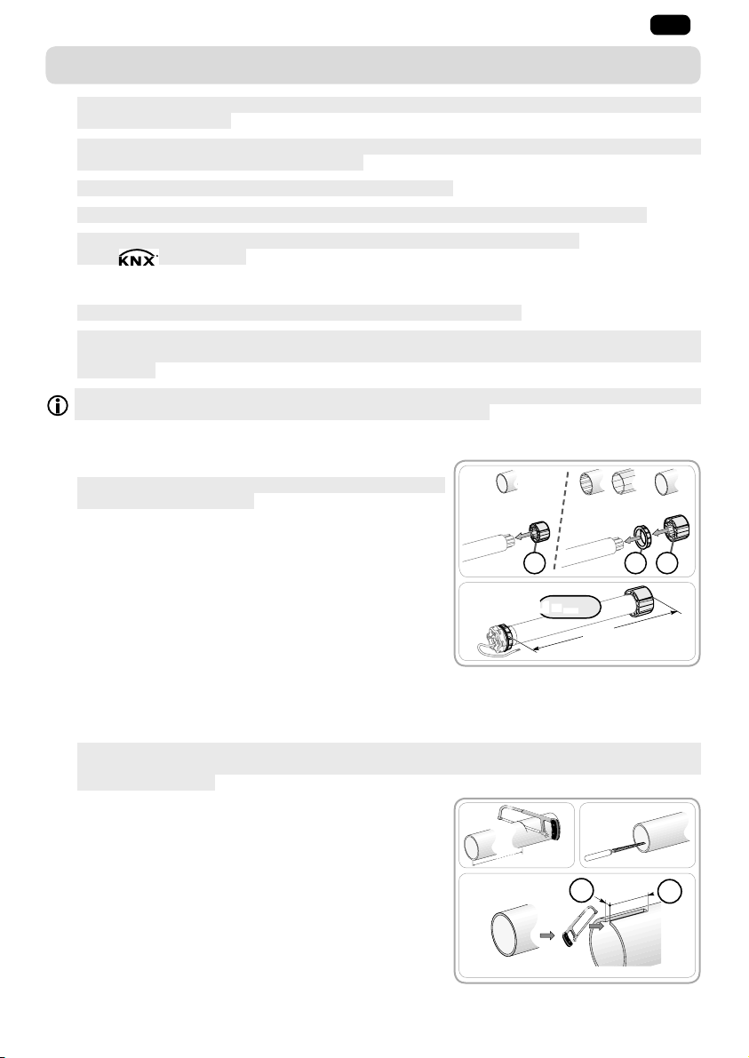
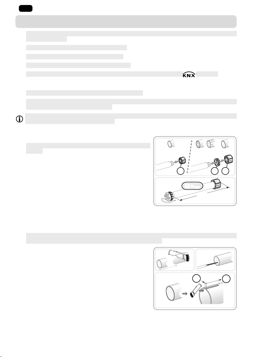
2. 1. 1. Préparation de la motorisation
S ’ a s s u r e r q u e l e d i a m è t r e i n t é r i e u r d u t u b e e s t s u p é r i e u r
1
ou égal à 47 mm.
1) Monter les accessoires nécessaires à l’intégration de la
motorisation dans le tube d’enroulement :
• Soit uniquement la roue a sur la motorisation.
• Soit la couronne b et la roue c sur la motorisation.
2) Mesurer la longueur (L1) entre le bord intérieur de la tête de
la motorisation et l’extrémité de la roue.
»).
1)
Ø = 47 mm
a
2)
L1 = …
Ø > 47 mm
cb
L1
2. 1. 2. Préparation du tube
I n s t a l l e r u n m o t e u r i l m o 5 0 W T d a n s u n t u b e d ’ e n r o u l e m e n t d ’ é p a i s s e u r m i n i d e 0 . 5 m m d o n t l a
1
face interne est lisse : pas de présence de soudure, sertissage, pliage, etc. à l’intérieur du tube.
1) Couper le tube d’enroulement à la longueur désirée en fonction du produit motorisé.
2) Ébavurer le tube d’enroulement et éliminer les copeaux.
3) Pour les tubes d’enroulement lisses, découper une encoche
selon les cotes suivantes :
• d = 4 mm (0.16 in)
• e = 28 mm (1.1 in)
2
Images non contractuelles
Copyright © 2015 Somfy SAS. All rights reserved.
1) 2)
3)
d
e
Page 5

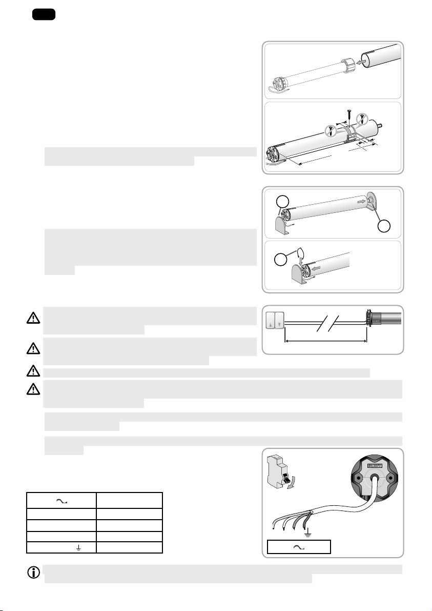
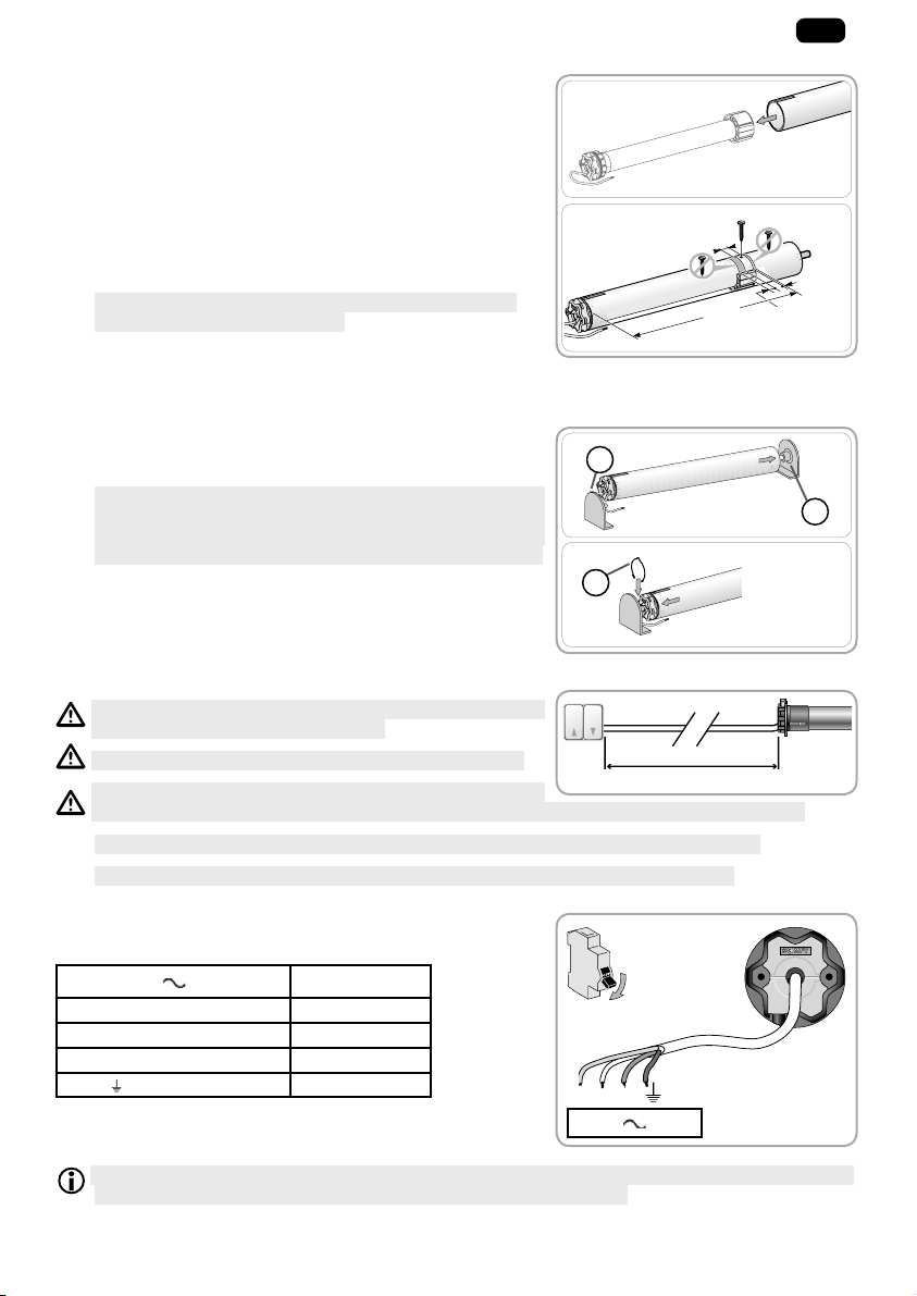
2. 1. 3. Assemblage motorisation - tube
1) Glisser le moteur dans le tube d’enroulement.
Pour les tubes d’enroulement lisses à l’intérieur,
positionner l’encoche découpée sur l’ergot de la couronne.
2) La roue doit être bloquée en translation dans le tube
d’enroulement:
• Soit en fixant le tube d’enroulement sur la roue à l’aide de
4 vis parker Ø 5 mm ou 4 rivets pop acier Ø 4,8 mm placés
entre 5 mm et 15 mm de l’extrémité extérieure de la roue,
quel que soit le tube d’enroulement.
Les vis ou les rivets pop ne doivent pas être fixés sur le
1
moteur mais uniquement sur la roue.
• Soit par l’utilisation d’un stop roue, pour les tubes non
lisses.
2. 1. 4. Montage de l’ensemble tube - motorisation
1) Monter et fi xer l’ensemble tube-motorisation sur le support
embout f et sur le support motorisation g :
S’assurer que l’ensemble tube-motorisation est verrouillé
1
sur le support embout. Cette opération permet d’éviter à
l’ensemble tube-motorisation de sortir de la fi xation du
support embout lorsque le volet roulant arrive en fi n de
course basse.
2) Suivant le type de support, mettre l’anneau d’arrêt h en place.
1)
2)
15 mm
L1
1)
g
2)
h
2. 2. CÂBLAGE
Respecter la Norme NF C 15-100 pour les installations
électriques.
Les câbles traversant une paroi métallique doivent être
protégés et isolés par un manchon ou un fourreau.
Attacher les câbles pour éviter tout contact avec une partie
en mouvement.
Si la motorisation est utilisée en extérieur, et si le câble d’alimentation est de type HO5-VVF alors
installer le câble dans un conduit résistant aux UV, par exemple sous goulotte.
Laisser le câble d’alimentation de la motorisation accessible : il doit pouvoir être remplacé
1
facilement.
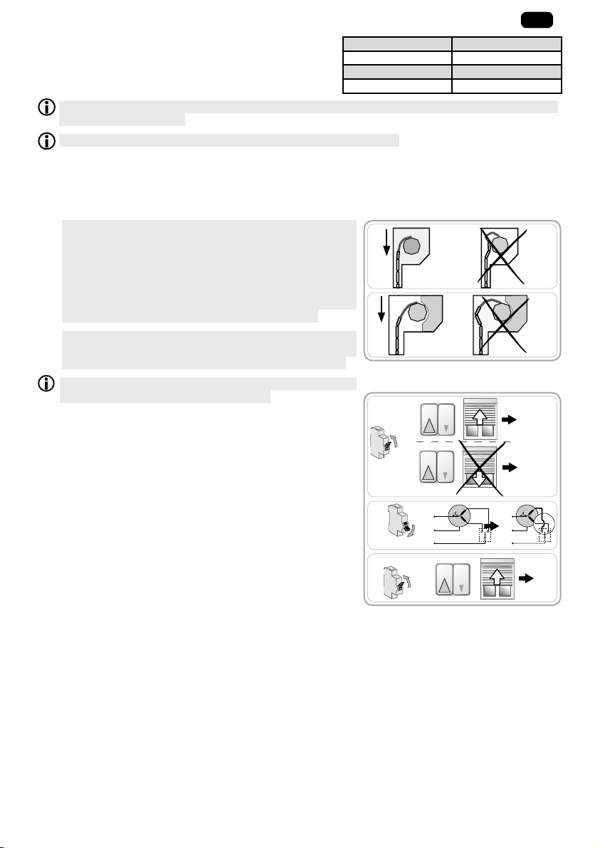
Tou jours fai re u ne bo ucl e sur l e câb le d ’ali menta tion po ur év ite r la pé nétrati on d’eau dans la
1
motorisation !
- Couper l’alimentation secteur.
- Connecter la motorisation selon les informations du tableau
ci-dessous :
230 V 50 Hz Câble
Neutre (N) Bleu
Phase (L1) Marron
Phase (L2) Noir
)Vert-Jaune
Terre (
N L1 L2
230 V 50 Hz
L ≤ 50 m
OFF
FR
5 mm
20 mm
f
S e l o n l e c o u r a n t d e c h a r g e m a x i m a l e d u p o i n t d e c o m m a n d e e t s e l o n l e s t y p e s d e m o t e u r s ,
plusieurs moteurs peuvent être connectés en parallèle à un point de commande.
Copyright © 2015 Somfy SAS. All rights reserved.
Images non contractuelles
3
Page 6
FR
Exemple d’un point de commande 3A :
P o u r l ’ i n t é g r a t i o n d u m o t e u r d a n s u n s y s t è m e S o m f y , p a r l ’ i n t e r m é d i a i r e d ’ u n m o t e u r c o n t r ô l e u r
Somfy, les exigences de connexion de la notice du contrôleur doivent être scrupuleusement
respectées.
L e s p o i n t s d e c o m m a n d e a v e c u n r e l a i s « s e m i - c o n d u c t e u r » n e d o i v e n t p a s ê t r e u t i l i s é s .
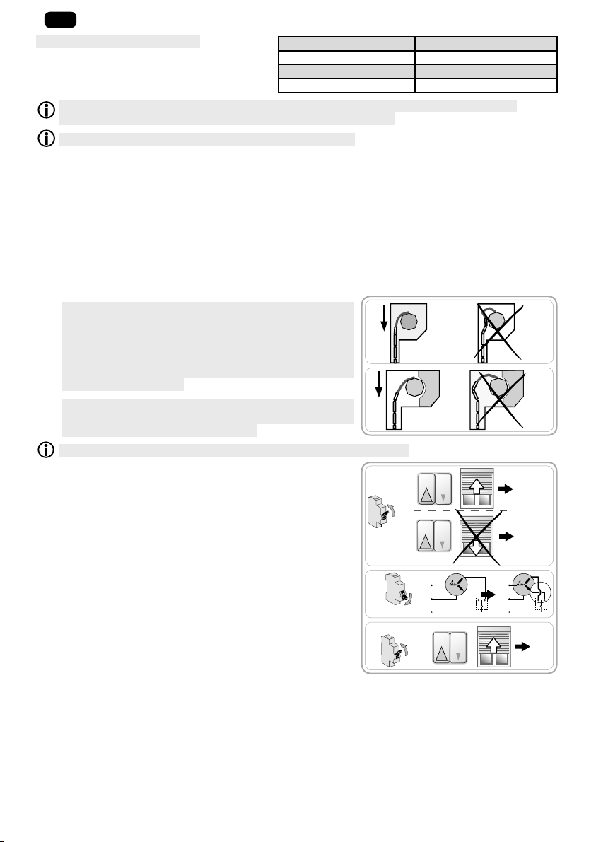
2. 3. MISE EN SERVICE
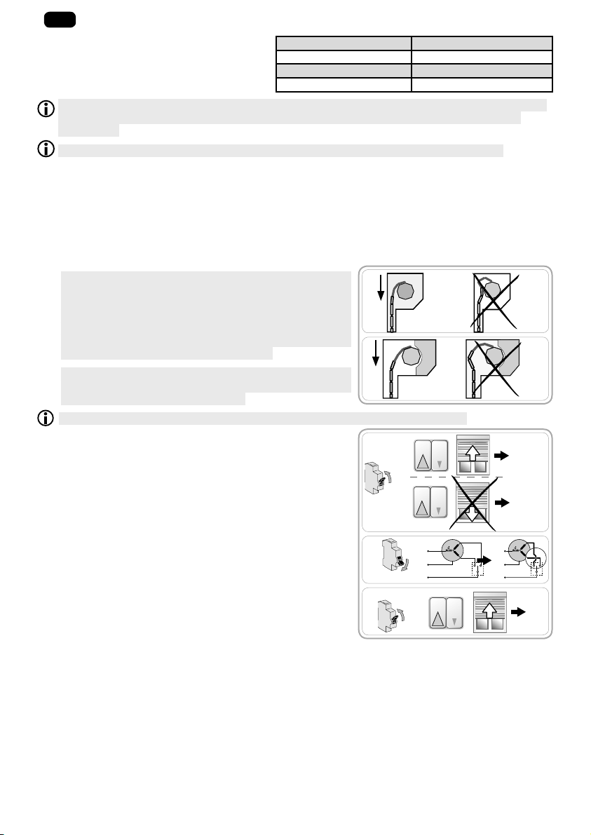
A p r è s a v o i r fi x é l e v o l e t r o u l a n t s u r l e t u b e d ’ e n r o u l e m e n t ,
1
s’assurer que, lorsque le volet roulant est en position de
fin de course basse, le lien rigide est correctement placé et
que la première lame entre dans les coulisses en position
verticale (force F). Si besoin ajuster le nombre de lames
utilisées pour améliorer la position du lien rigide lorsque
le volet roulant est en fin de course basse.
T o u j o u r s s e r e p o r t e r a u x a b a q u e s e t a u x p r é c o n i s a t i o n s
1
de montage du fabricant de liens rigides pour sélectionner
ceux adaptés au volet roulant utilisé.
Utiliser au moins 2 liens rigides pour fixer le volet roulant au tube d’enroulement.
1) Rétablir le courant.
- Appuyer sur le bouton « Montée » du point de commande :
• S i l e v o l e t r o u l a n t m o n t e , l e c â b l a g e e s t c o r r e c t e t l a m i s e
en service terminée.
• S i l e v o l e t r o u l a n t d e s c e n d , p a s s e r à l ’é t a p e s u i v a n t e .
2) Couper le courant.
- Inverser le fil marron et le fil noir reliés au point de commande.
3) Rétablir le courant.
- Appuyer sur le bouton « Montée » pour contrôler le sens de
rotation.
Couple en Nm Quantité max. de moteurs
6 5
10 4
20 2
F
F
1
ON
2
OFF
3
ON
OK
2
OK
4
Images non contractuelles
Copyright © 2015 Somfy SAS. All rights reserved.
Page 7
2. 4. ASTUCES ET CONSEILS D’INSTALLATION
2. 4. 1. Questions sur l’ilmo 50 WT ?
Problèmes Causes possibles Solutions
Le volet roulant
tourne dans le
mauvais sens.
Le volet roulant
ne fonctionne
pas.
Le volet roulant
s’arrête trop tôt.
Le volet roulant
ne s’arrête pas
en fin de course
basse.
Le volet roulant
ne s’arrête pas
en fin de course
haute.
Le câblage est incorrect. Contrôler le câblage et le modifier si besoin.
Le câblage est incorrect. Contrôler le câblage et le modifier si besoin.
La motorisation est au thermique. Attendre que la motorisation refroidisse.
Le point de commande n’est pas
compatible.
Le volant roulant subit des
frottements lors de ses
déplacements : frottement
au niveau des coulisses, du
coffre, interférence entre le tube
Contrôler la compatibilité et remplacer le
point de commande si besoin.
Contrôler l’installation du volet roulant et
corriger les éventuels frottements.
Si le problème persiste, remettre la
motorisation en configuration d’origine.
d’enroulement et la motorisation,
etc.
La motorisation a été installée dans
un nouveau volet roulant.
Remettre la motorisation en configuration
d’origine, voir chapitre «Retour en
configuration d’origine ».
Les fixations utilisées ne sont pas
adaptées.
Le système de blocage du volet
roulant en position haute n’est pas
adapté.
Contrôler que le volet roulant est fixé au tube
d’enroulement avec des liens rigides.
Contrôler que le volet roulant est équipé
de butées vissées sur la lame finale, de
butées fixes ou amovibles intégrées dans les
coulisses ou d’une lame finale faisant office
de butée.
FR
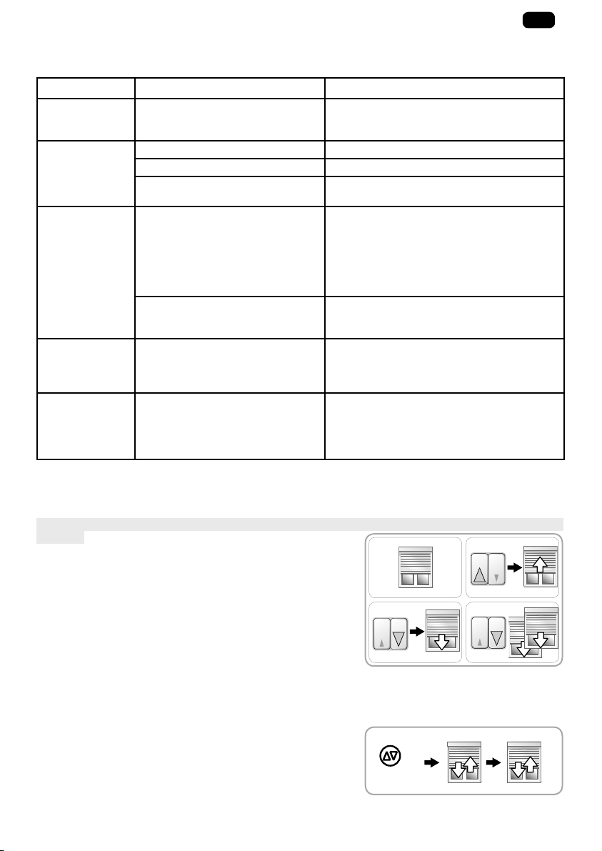
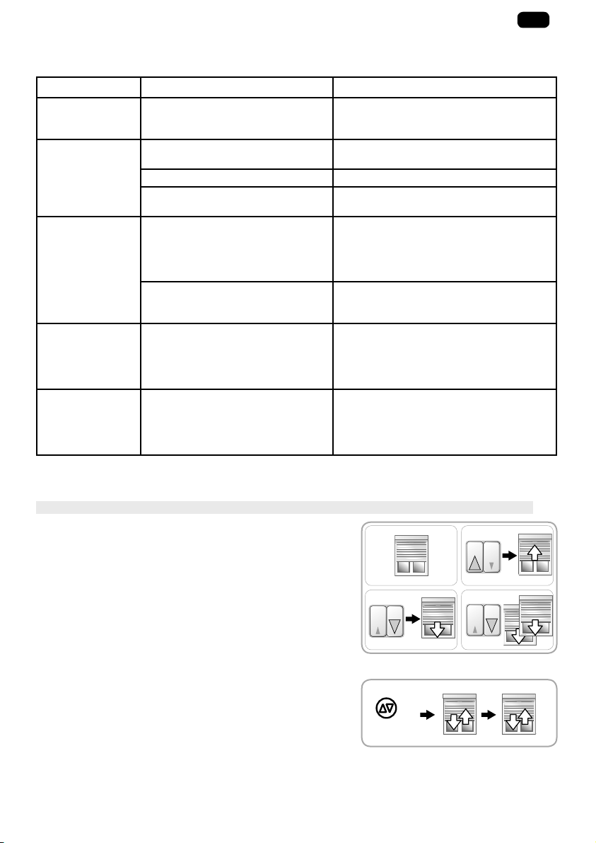
2. 4. 2. Retour en configuration d’origine
2. 4. 2. 1. Avec le point de commande relié au volet roulant
Suivre rigoureusement chacune des 4 étapes de la procédure afin de réussir le retour en configuration
d’origine.
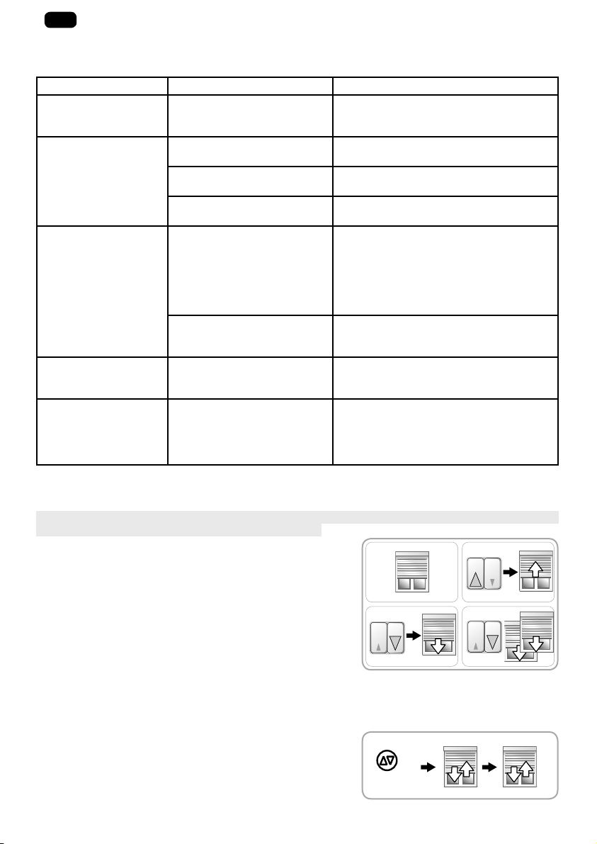
1) Mettre le volet roulant à mi-hauteur.
2) Répéter l’étape suivante 3 fois de suite :
• Appuyer sur le bouton « Montée » jusqu’à ce que le volet
roulant bouge. Relâcher immédiatement le bouton.
3) Répéter l’étape suivante 2 fois de suite :
• Appuyer sur le bouton « Descente » jusqu’à ce que le volet
1 2
x 3
3 4
roulant bouge. Relâcher immédiatement le bouton.
4) Appuyer de nouveau sur le bouton « Descente » jusqu’à ce
x 2
que le volet roulant effectue 2 mouvements successifs dans
le même sens.
• L a m o t o r i s a t i o n e s t r é i n i t i a l i s é e e n c o n fi g u r a t i o n d ’ o r i g i n e .
2. 4. 2. 2. Avec le câble de réglage pour moteur électronique filaire
- Appuyer en même temps sur le bouton « Montée » et le
bouton « Descente » du câble de réglage jusqu’à ce que le
volet roulant effectue un premier puis un second va-et-vient.
• L a m o t o r i s a t i o n e s t d e n o u v e a u e n c o n fi g u r a t i o n d ’ o r i g i n e .
7s
Copyright © 2015 Somfy SAS. All rights reserved.
Images non contractuelles
5
Page 8
FR
3. UTILISATION ET MAINTENANCE
Cette motorisation ne nécessite pas d’opération de maintenance
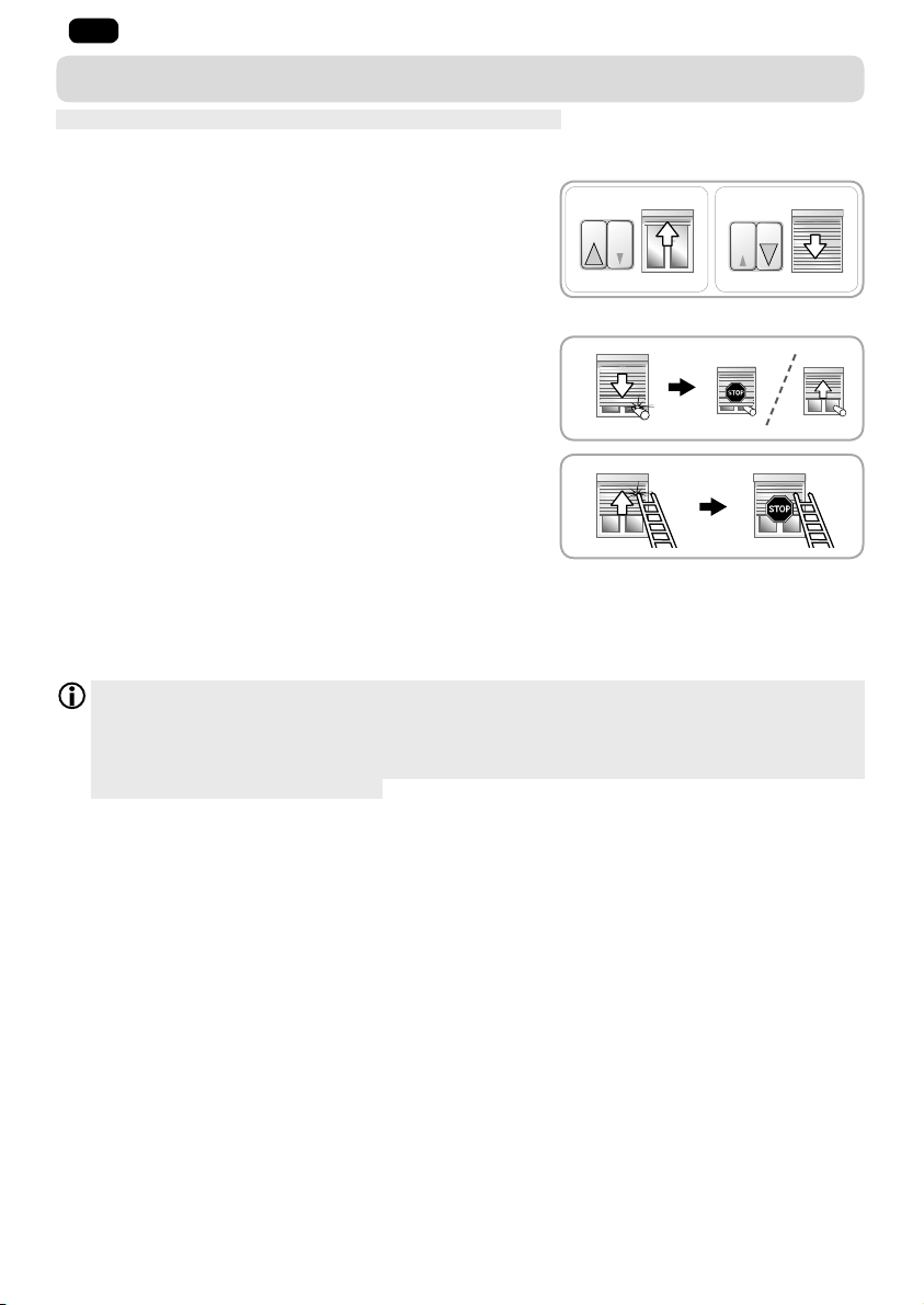
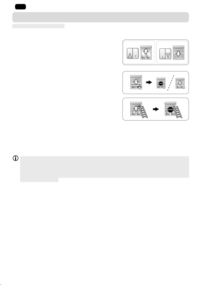
3. 1. MONTÉE ET DESCENTE DU VOLET ROULANT
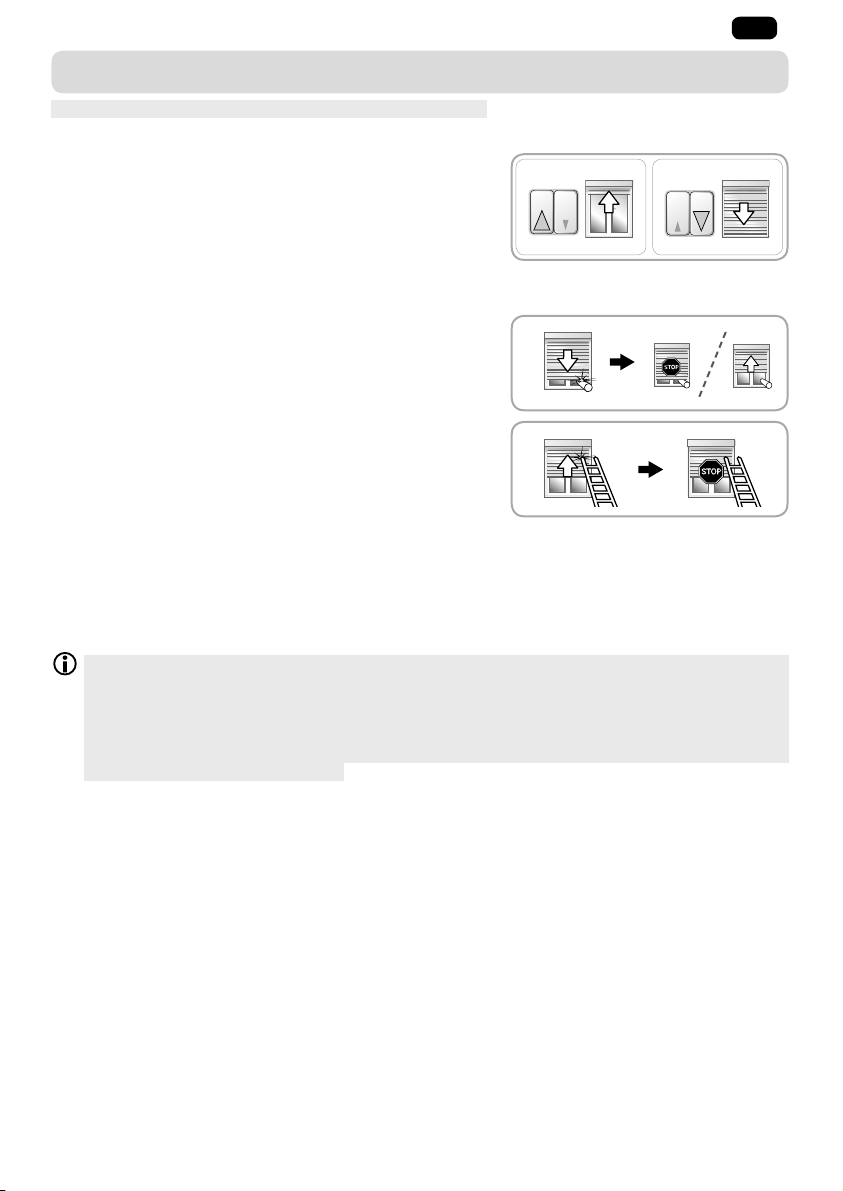
1) Appuyer sur le bouton « Montée » :
• L e v o l e t r o u l a n t m o n t e e t s ’ a r r ê t e e n b u t é e h a u t e s a n s
avoir besoin de faire de réglage.
2) Appuyer sur le bouton « Descente » :
• L e v o l e t r o u l a n t d e s c e n d e t s ’ a r r ê t e e n b u t é e b a s s e s a n s
avoir besoin de faire de réglage.
3. 2. DÉTECTION DES OBSTACLES
La détection automatique des obstacles permet de protéger le
tablier du volet roulant et de dégager les obstacles :
- Si le tablier du volet roulant rencontre un obstacle à la
descente, le volet roulant s’arrête automatiquement :
• Appuyer sur le bouton « Montée » pour débloquer le volet
roulant.
- Si le tablier du volet roulant rencontre un obstacle à la
montée, le volet roulant s’arrête automatiquement.:
• Appuyer sur le bouton « Descente » pour débloquer le
volet roulant.
3. 3. PROTECTION CONTRE LE GEL
La protection contre le gel fonctionne comme la détection des obstacles :
- Si la motorisation détecte une résistance, elle ne se met pas en marche pour protéger le tablier du
volet roulant :
• Le volet roulant reste en position initiale.
L a p r o t e c t i o n a u t o m a t i q u e c o n t r e l e g e l é v i t e u n e n d o m m a g e m e n t d u t a b l i e r l o r s q u e l e g i v r e b l o q u e
la dernière lamelle contre le rebord de fenêtre. Si le tablier est (complètement) gelé dans les
coulisses ou si des lamelles sont bloquées entre elles par du givre, le fonctionnement de la
protection contre le gel peut, en revanche, être limité. Dans ce cas, un endommagement du tablier
n’est pas complètement exclu. Ce type de gel du tablier est très rare. Si cela se produit, attendre le
dégel avant d’utiliser le volet roulant.
1 2
6
Images non contractuelles
Copyright © 2015 Somfy SAS. All rights reserved.
Page 9
4. ASTUCES ET CONSEILS D’UTILISATION
Questions sur l’ilmo 50 WT ?
Problèmes Causes possibles Solutions
Le volet roulant ne fonctionne
pas.
La motorisation est au
thermique.
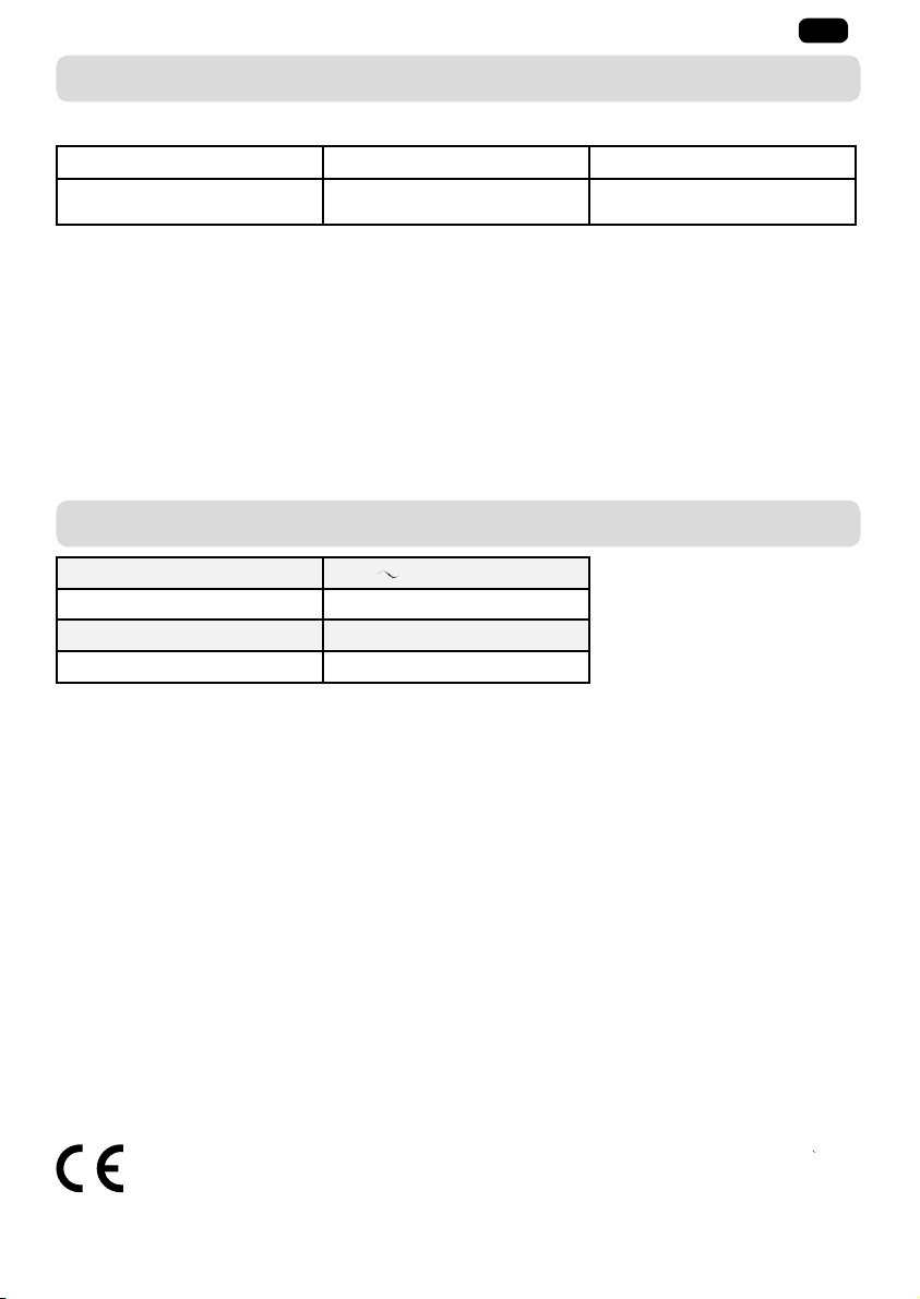
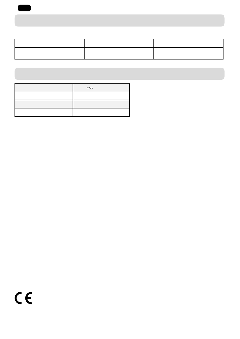
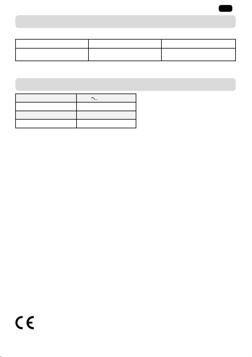
5. DONNÉES TECHNIQUES
Alimentation 230 V 50 Hz
Température d’utilisation - 20 °C à + 60 °C
Indice de protection IP 44
Isolation électrique Classe I
FR
Attendre que la motorisation
refroidisse.
Par la pr ésente, So mfy déc lare que la mot orisati on couver te par ces ins tructi ons, marq uée pour être al imenté e en 23 0V 50Hz et
util isée comm e i ndiqué da ns ces instr uction s, est confo rme aux exi gences es sentie lles des Dir ective s 20 06/42/EC et 2014/3 0/EU.
Une déc larati on de conformité dét aillan t le s n ormes et les sp écifica tions utili sées et préc isant tou s le s détai ls pour l’id entifica tion
de la moto risatio n, le nom et l’adres se de la (des) perso nne(s) autoris ée(s) à consti tuer le dossi er techniq ue et habilit ée à ét ablir la
déc laratio n compre nant le lie u et la date d ’émiss ion, est d isponib le à l’adre sse Inter net ww w.somfy. com/ce.
Copyright © 2015 Somfy SAS. All rights reserved.
Images non contractuelles
7
Page 10

DE
ORIGINALANLEITUNG
Diese Anleitung gilt für alle Antriebe vom Typ ilmo50WT, deren Ausführungen im aktuellen Katalog zu finden sind.
INHALT
1. Vorbemerkungen 8
1. 1. Anwendungsbereich 8
1. 2. Ha-ung 8
2. Installation 9
2. 1. Montage 9
2. 2. Verkabelung 10
2. 3. Inbetriebnahme 11
2. 4. Tipps und Empfehlungen für die Installation 12
Der Antrieb ilmo 50 WT bedarf keiner Einstellungen: Er ist nach dem Anschließen sofort betriebsbereit.
Die Endlageneinstellungen des ilmo 50 WT erfolgen automatisch.
Der Antrieb ilmo 50 WT kann sowohl rechts als auch links montiert werden. Er wird mit einem verriegelten Schalter
oder Taster angesteuert.
Der Antrieb ilmo 50 WT verfügt über:
- Eine Hinderniserkennung, die im Falle von Hindernissen Beschädigungen des Rollladenpanzers beim
Herunterfahren verhindert;
- Einen Festfrierschutz, der beim Festfrieren des Rollladens Beschädigungen des Rollladenpanzers beim
Hochfahren verhindert.
1. VORBEMERKUNGEN
1. 1. ANWENDUNGSBEREICH
Der Antrieb ilmo 50 wurde für den Antrieb aller Arten von Rollläden mit Anschlägen und festen
Wellenverbindern entwickelt.
Der Installateur muss Fachmann für Antriebe und Automatisierungstechnik im Wohnungsbau sein und
sicherstellen, dass der Behang nach der Installation den Normen entspricht, die im Installationsland
gelten, namentlich der Rollladennorm EN 13659.
1. 2. HAFTUNG
Lesen Sie bitte diese Installationsanleitung sorgfältig durch, bevor Sie den Antrieb montieren und
in Betrieb nehmen. Beachten Sie außer den Anweisungen in dieser Anleitung auch die detaillierten
Hinweise im beiliegenden Dokument Sicherheitshinweise.
Die Installation des Antriebs muss von einem Fachmann für Gebäudeautomation unter Einhaltung der
Anweisungen von Somfy und der am Ort der Inbetriebnahme geltenden Vorschri"en vorgenommen
werden.
Jede Nutzung des Antriebs zu Zwecken, die über den im vorliegenden Dokument beschriebenen
Anwendungsbereich hinausgehen, ist untersagt. Jede Missachtung dieser sowie aller anderen in dieser
Anleitung und im beiliegenden Dokument Sicherheitshinweise enthaltenen Anweisungen führt zum
Ausschluss jeglicher Ha-ung und Gewährleistungsansprüche durch Somfy.
Der Installateur hat seine Kunden auf die Nutzungs- und Wartungsbedingungen des Antriebs
hinzuweisen und ihnen diese sowie das beiliegende Dokument Sicherheitshinweise nach Abschluss
der Installation des Antriebs auszuhändigen. Wartungs- und Reparaturarbeiten für den Antrieb dürfen
ausschließlich von Fachleuten für Gebäudeautomation ausgeführt werden.
Für Fragen zur Installation des Antriebs und weiterführenden Informationen wenden Sie sich bitte an Ihren
Somfy-Ansprechpartner, oder besuchen Sie unsere Website www.somfy.com.
3. Verwendung und Wartung 13
3. 1. Auf- und Abfahren des Rollladens 13
3. 2. Hinderniserkennung 13
3. 3. Festfrierschutz 13
4. Tipps und Empfehlungen für die Anwendung 14
5. Technische Daten 14
Sicherheitshinweis!
8
Abbildungen nicht bindend.
Achtung! Information
1
Copyright © 2015 Somfy SAS. All rights reserved.
Page 11
2. INSTALLATION
D i e f o l g e n d e n A n w e i s u n g e n s i n d v o m F a c h m a n n , d e r d i e I n s t a l l a t i o n d e s A n t r i e b s a u s f ü h r t ,
1
unbedingt zu beachten.
Lassen Sie den Antrieb niemals fallen, bewahren Sie ihn vor Erschütterungen, bohren Sie ihn nicht
1
an und tauchen Sie ihn nicht in Flüssigkeiten.
Installieren Sie für jeden Antrieb eine eigene Bedieneinheit.
1
Schließen Sie niemals zwei verschiedene Bedieneinheiten an ein und denselben Motor an.
1
Überprüfen Sie die Kompatibilität, wenn Sie den Antrieb mit einem Bussystem
1
(z. B. „ “) verwenden.
2. 1. MONTAGE
Überprüfen Sie die Belastbarkeit des Rollladens und seines Zubehörs.
1
U m e i n e B e s c h ä d i g u n g d e s R o l l l a d e n s u n d / o d e r d e s S o m f y - P r o d u k t e s a u s z u s c h l i e ß e n ,
1
vergewissern Sie sich bitte, dass der verwendete Antrieb für die betreffende Rollladengröße
geeignet ist.
F ü r w e i t e r e I n f o r m a t i o n e n z u r K o m p a t i b i l i t ä t d e s A n t r i e b s m i t d e m R o l l l a d e n u n d d e s s e n Z u b e h ö r
wenden Sie sich bitte an den Rollladen-Hersteller oder an Somfy.
DE
2. 1. 1. Vorbereitung des Antriebs
A c h t e n S i e d a r a u f , d a s s d e r I n n e n d u r c h m e s s e r d e r W e l l e
1
mindestens 47 mm beträgt.
1) Bringen Sie die erforderlichen Zubehörteile zur Montage
des Antriebs an der Welle an:
• Entweder nur den Mitnehmer a am Antrieb.
• Oder den Adapter b und den Mitnehmer c am Antrieb.
2) Messen Sie die Länge (L1) zwischen dem Innenrand des
Antriebskopfes und dem äußersten Ende des Mitnehmers.
1)
Ø = 47 mm
a
2)
L1 = …
L1
2. 1. 2. Vorbereitung der Welle
I n s t a l l i e r e n S i e d e n A n t r i e b i l m o 5 0 W T i n e i n e r W e l l e m i t e i n e r W a n d s t ä r k e v o n m i n d e s t e n s 0 , 5
1
mm und einer glatten Innenfläche (keine Schweißnähte, Verformungen oder Biegungen auf der
Innenseite der Welle).
1) Schneiden Sie die Welle auf die gewünschte Länge zu.
2) Entgraten Sie die Welle und entfernen Sie die Späne.
3) Versehen Sie die Präzisionsrohre, unter Berücksichtigung
folgender Maße, mit einer Ausklinkung:
• d = 4 mm (0.16 Zoll)
• e = 28 mm (1.1 Zoll)
1) 2)
3)
d
Ø > 47 mm
cb
e
Copyright © 2015 Somfy SAS. All rights reserved.
Abbildungen nicht bindend.
9
Page 12
DE
2. 1. 3. Zusammenbau von Antrieb und Welle
1) Führen Sie den Antrieb in die Welle ein.
Positionieren Sie bei auf der Innenseite glatten Wellen die
Ausklinkung am Führungszapfen des Adapters.
2) Der Mitnehmer muss im Inneren der Welle gegen
Verschieben gesichert werden:
• Entweder durch Befestigung der Welle am Mitnehmer durch
4 selbstschneidende Schrauben mit einem Durchmesser
von Ø 5 mm oder durch 4 Edelstahl-Blindnieten mit einem
Durchmesser von Ø 4,8 mm, die zwischen 5 mm und 15
mm vom äußeren Ende des Mitnehmers entfernt an der
Welle angebracht werden.
Die Schrauben bzw. Blindnieten dürfen nur am Mitnehmer
1
angebracht werden, niemals am Antrieb.
• Oder durch Verwendung einer Aufschraubkappe für Wellen
mit Innengewinde.
2. 1. 4. Einbau der Wellen-Antriebs-Einheit
1) Bringen Sie die Wellen-Antriebs-Einheit am Gegenlager f und
am Antriebslager g an:
Vergewissern Sie sich, dass die Wellen-Antriebs-Einheit
1
am Gegenlager verriegelt ist. Damit wird verhindert, dass
sich die Befestigung der Welle mit dem Antrieb vom
Gegenlager löst, wenn der Rollladen seine untere Endlage
erreicht.
2) Bringen Sie, je nach Art des Lagers, den Federring h an.
2. 2. VERKABELUNG
Errichten, Prüfen, Inbetriebsetzen and Fehlerbehebung der
Anlage darf nur von einer Elektrofachkra- durchgeführt
werden (DIN VDE 1000-10).
Alle Kabel, die in Kontakt mit einer metallischen Wandung
geraten könnten, müssen mit einer Hülse oder
Ummantelung geschützt und isoliert werden.
Bringen Sie die Kabel so an, dass sie nicht in Kontakt zu beweglichen Teilen geraten können.
Wenn der Antrieb im Freien eingesetzt wird und wenn ein Versorgungskabel des Typs H05-VVF
verwendet wird, muss dieses in einem UV-beständigen Kabelrohr, zum Beispiel in einem
Kabelkanal verlegt werden.
Achten Sie darauf, dass das Netzkabel des Antriebs zugänglich bleibt: Es muss sich einfach
1
austauschen lassen.
Sehen Sie eine Schleife im Netzkabel vor, um das Eindringen von Wasser in den Antrieb zu
1
vermeiden
- Unterbrechen Sie die Spannungsversorgung.
- Schließen Sie den Antrieb gemäß den Angaben in unten
stehender Tabelle an:
230 V 50 Hz Kabel
Neutralleiter (N) Blau
Phase (L1) Braun
Phase (L2) Schwarz
Schutzleiter (
)Gelb/grün
1)
2)
1)
g
2)
h
AUS
N L1 L2
230 V 50 Hz
15 mm
L1
L ≤ 50 m
5 mm
20 mm
f
A b h ä n g i g v o n d e r B e l a s t b a r k e i t d e r S t e u e r u n g u n d d e r v e r w e n d e t e n A n t r i e b s v a r i a n t e , k ö n n e n
mehrere Antriebe an einer Bedieneinheit parallel angeschlossen werden.
10
Abbildungen nicht bindend.
Copyright © 2015 Somfy SAS. All rights reserved.
Page 13
Beispiel für eine Steuerung mit 3 A Belastbarkeit:
Drehmoment Nm max. Anzahl
6 5
10 4
20 2
B e i E i n b i n d u n g d e s A n t r i e b s i n e i n S o m f y - S y s t e m ü b e r e i n e n A k t o r s i n d d i e A n s c h l u ß v o r s c h r i - e n
des Aktors zu beachten.
A k t o r e n m i t H a l b l e i t e r r e l a i s / T r i a c s d ü r f e n n i c h t v e r w e n d e t w e r d e n .
2. 3. INBETRIEBNAHME
S t e l l e n S i e n a c h d e m B e f e s t i g e n d e s R o l l l a d e n s a n d e r
1
Welle sicher, dass der feste Wellenverbinder so platziert
ist, dass das oberste Profil senkrecht in die
Führungsschienen einläu-, wenn sich der Rollladen in der
unteren Endlage befindet (Kra- F). Verändern Sie
gegebenenfalls die Anzahl der verwendeten Profile, um
die Stellung des Wellenverbinders zu korrigieren, wenn
sich der Rollladen in der unteren Endlage befindet.
Z i e h e n S i e d i e T a b e l l e n u n d M o n t a g e a n l e i t u n g e n d e s
1
Herstellers der festen Wellenverbinder zurate, um die für
den jeweiligen Rollladen geeigneten Teile auszuwählen.
Verwenden Sie mindestens 2 feste Wellenverbinder, um
den Rollladen an der Welle zu befestigen.
1) Schalten Sie die Spannungsversorgung wieder ein.
- Drücken Sie auf die AUF-Taste der Bedieneinheit:
• B e w e g t s i c h d e r R o l l l a d e n a u f w ä r t s , i s t d i e I n b e t r i e b n a h m e
beendet.
• Bewegt sich der Rollladen abwärts, gehen Sie bitte wie folgt
vor.
2) Schalten Sie die Spannungsversorgung aus.
- Vertauschen Sie das braune und das schwarze Kabel an der
Bedieneinheit.
3) Schalten Sie die Spannungsversorgung wieder ein.
- Drücken Sie auf die AUF-Taste, um die Drehrichtung zu
überprüfen.
F
F
1
EIN
2
AUS
3
EIN
DE
OK
2
OK
Copyright © 2015 Somfy SAS. All rights reserved.
Abbildungen nicht bindend.
11
Page 14
DE
2. 4. TIPPS UND EMPFEHLUNGEN FÜR DIE INSTALLATION
2. 4. 1. Fragen zum ilmo 50 WT?
Störungen Mögliche Ursachen Lösungen
Der Rollladen bewegt
sich in die falsche
Richtung.
Der Rollladen
funktioniert nicht.
Der Rollladen hält zu
früh an.
Der Rollladen hält nicht
in der unteren Endlage
an.
Der Rollladen hält nicht
in der oberen Endlage
an.
2. 4. 2. Rücksetzen auf Werkseinstellung
Die Verkabelung ist fehlerha-. Die Verkabelung überprüfen und ggf.
ändern.
Die Verkabelung ist fehlerha-. Die Verkabelung überprüfen und ggf.
ändern.
Der Überhitzungsschutz des
Warten S ie ab, bis der Antrieb abgekühlt ist.
Antriebs wurde ausgelöst.
Die Bedieneinheit ist nicht
kompatibel.
Der Rollladen unterliegt
während der Bewegungen
einer Reibung an den
Führungsschienen oder am
Kasten, oder einer Interferenz
zwischen Welle und Antrieb,
Die Kompatibilität überprüfen und die
Bedieneinheit ggf. austauschen.
Kontrollieren Sie die Montage des
Rollladens und korrigieren Sie eventuelle
Reibstellen.
Falls der Fehler weiter besteht, den Antrieb
auf die Werkseinstellungen zurücksetzen.
usw.
Der Antrieb wurde in einen
neuen Rollladen eingebaut.
Setzen Sie den Antrieb auf die
Werkseinstellungen zurück, siehe Abschnitt
"Rücksetzen auf Werkseinstellung".
Die verwendeten Befestigungen
sind nicht geeignet.
Vergewissern Sie sich, dass der Rollladen
über feste Wellenverbinder an der Welle
befestigt ist.
Das Verriegelungssystem
des Rollladens in der oberen
Endlage entspricht nicht den
Anforderungen.
Kontrollieren Sie, ob an der Endleiste
verschraubte Stopper, feste bzw.
abnehmbare Stopper in der Führungsschiene
oder eine Endleiste, die als Stopper fungiert,
vorhanden sind.
2. 4. 2. 1. Über die Bedieneinheit des Rollladens
Befolgen Sie unbedingt jeden einzelnen der 4 nachfolgend beschriebenen Schritte, um das Zurücksetzen
auf Werkseinstellung mit Erfolg durchführen zu können.
1) Bewegen Sie den Rollladen, bis er auf halber Höhe ist.
2) Wiederholen Sie den Schritt 3-mal hintereinander:
• Drücken Sie auf die AUF-Taste, bis sich der Rollladen in
Bewegung setzt. Lassen Sie anschließend den Knopf
sofort wieder los.
3) Wiederholen Sie den folgenden Schritt 2-mal hintereinander:
• Drücken Sie auf die AB-Taste, bis sich der Rollladen in
1 2
x 3
3 4
Bewegung setzt. Lassen Sie anschließend den Knopf
sofort wieder los.
4) Drücken Sie erneut auf die AB-Taste, bis der Rollladen 2
x 2
aufeinander folgende Bewegungen in die gleiche Richtung durchführt.
• D e r A n t r i e b w u r d e j e t z t i n s e i n e W e r k s e i n s t e l l u n g z u r ü c k g e s e t z t .
2. 4. 2. 2. Mit Einstellkabel für einen drahtgebundenen elektronischen Antrieb
- Drücken Sie gleichzeitig auf die Tasten AUF/AB des
Einstellkabels, bis der Rollladen erst eine und dann noch
eine zweite Auf-/Ab-Bewegung ausführt.
• D e r A n t r i e b i s t n u n a u f d i e W e r k s e i n s t e l l u n g z u r ü c k g e s e t z t .
7s
12
Abbildungen nicht bindend.
Copyright © 2015 Somfy SAS. All rights reserved.
Page 15
DE
3. VERWENDUNG UND WARTUNG
Für diesen Antrieb sind keine Wartungsarbeiten erforderlich.
3. 1. AUF# UND ABFAHREN DES ROLLLADENS
1) Drücken Sie auf die AUF-Taste:
• D e r R o l l l a d e n f ä h r t h o c h u n d b l e i b t b e i E r r e i c h e n d e r
oberen Endlage stehen, ohne dass eine Einstellung nötig
ist.
2) Drücken Sie auf die AB-Taste:
• D e r R o l l l a d e n f ä h r t r u n t e r u n d b l e i b t b e i E r r e i c h e n d e r
unteren Endlage stehen, ohne dass eine Einstellung nötig ist.
3. 2. HINDERNISERKENNUNG
Die automatische Hinderniserkennung schützt den Rollladenpanzer
vor Schäden und ermöglicht das Entfernen der Hindernisse:
- Falls der Rollladenpanzer bei der Abwärtsbewegung auf ein
Hindernis trifft, stoppt der Behang automatisch:
• Drücken Sie auf die AUF-Taste, um den Rollladen zu
entsperren.
- Falls der Rollladenpanzer bei der Aufwärtsbewegung auf ein
Hindernis trifft, stoppt der Behang automatisch:
• Drücken Sie auf die AB-Taste, um den Rollladen zu
entsperren.
3. 3. FESTFRIERSCHUTZ
Der Festfrierschutz funktioniert wie die Hinderniserkennung:
- Erkennt der Antrieb einen Widerstand, setzt er sich, um eine Beschädigungen des Rollladenpanzers
zu vermeiden, nicht in Bewegung:
• Der Rollladen verbleibt in seiner ursprünglichen Position.
12
D e r a u t o m a t i s c h e F e s t f r i e r s c h u t z v e r h i n d e r t e i n e B e s c h ä d i g u n g d e s P a n z e r s , w e n n d i e l e t z t e
Lamelle des Panzers an der Fensterbank festgefroren ist. Beim (kompletten) Festfrieren des
Panzers in den Führungsschienen oder beim Festfrieren einzelner Lamellen untereinander ist
hingegen die Funktionalität des Festfrierschutzes möglicherweise eingeschränkt, so dass
Beschädigungen des Panzers nicht mit Sicherheit ausgeschlossen werden können. Ein derartiges
Einfrieren des Panzers ist sehr selten. Sehen Sie in diesem Fall von einer Bedienung des Rollladens
ab, bis sich die Vereisung gelöst hat.
Copyright © 2015 Somfy SAS. All rights reserved.
Abbildungen nicht bindend.
13
Page 16
DE
4. TIPPS UND EMPFEHLUNGEN FÜR DIE ANWENDUNG
Fragen zum ilmo 50 WT?
Störungen Mögliche Ursachen Lösungen
Der Rollladen funktioniert nicht. Der Überhitzungsschutz des
Antriebs wurde ausgelöst.
Warten S ie ab, bis der Antrieb
abgekühlt ist.
5. TECHNISCHE DATEN
Betriebsspannung 230 V 50 Hz
Tem pera tur bere ich - 20 °C bis + 6 0 °C
Schutzart IP 44
Schutzklasse Klasse I
Somf y erklär t hiermi t, dass der in di eser Anle itung bes chrieb ene Antr ieb bei best immung sgemäß em Einsat z u nd angesc hlosse n
an eine 2 30 V / 50 Hz- Stromver sorgung die grundl egende n Anfo rderun gen de r Rich tlinien 2006/42/ EG und 2014/30/EG erfü llt.
Eine mit Ausstel lungsd atum u nd -or t ver sehene CE-Kon formit ätserk lärung mit einer Aufzäh lung aller anwend baren Normen
und techni schen Spez ifikation en und aller z ur Iden tifizier ung de s Antri ebs er forderl ichen Detail s sowie der An gabe de r Namen
und Adress en der Person (en), die berec htigt s ind, di e tech nische n Unter lagen zu ers tellen und zu beglau bigen, kann unter d er
Internet- Adresse w ww.so mfy.com /ce einge sehen we rden.
14
Abbildungen nicht bindend.
Copyright © 2015 Somfy SAS. All rights reserved.
Page 17

EN
ORIGINAL GUIDE
These instructions apply to all ilmo50WT drives, the different versions of which are available in the
current catalogue.
CONTENTS
1. Prerequisite information 15
1. 1. Area of application 15
1. 2. Liability 15
2. Installation 16
2. 1. Installation 16
2. 2. Wiring 17
2. 3. Commissioning 18
2. 4. Tips and recommendations for installation 19
The ilmo 50 WT is a non-adjustable motor: a simple connection is all that is required.
The ilmo 50 WT programs its end limits automatically.
The ilmo 50 WT can be mounted either on the right or the le-. It can be controlled from a control point with a
fixed position or momentary action-type switch.
The ilmo 50 WT is equipped with:
- obstacle protection to protect the roller shutter when it is being lowered.
- anti-freeze protection to protect the roller shutter when it is being raised.
1. PREREQUISITE INFORMATION
1. 1. AREA OF APPLICATION
The ilmo 50 drive is designed to drive all types of roller shutters equipped with rigid links and
stops.
The professional motorisation and home automation installer must ensure that, once installed, the installation
of the motorised product complies with the standards in force in the country in which it is commissioned such
as, for example, the EN13659 roller shutters standard.
3. Use and maintenance 20
3. 1. Raising and lowering the roller shutter 20
3. 2. Obstacle detection 20
3. 3. Anti-freeze protection 20
4. Tips and recommendations for use 21
5. Technical data 21
1. 2. LIABILITY
Please read these instructions carefully before installing and using the drive. In addition to following the
instructions given in this guide, the instructions detailed in the attached Safety instructions document
must also be observed.
The drive must be installed by a motorisation and home automation professional, according
to instructions from Somfy and the regulations applicable in the country in which it is
commissioned.
It is prohibited to use the drive outside the field of application described above. Such use, and any failure to
comply with the instructions given in this guide and in the attached Safety instructions document, absolves
Somfy of any liability and invalidates the warranty.
The installer must inform its customers of the operating and maintenance conditions for the drive and must
provide them with the instructions for use and maintenance, and the attached
a-er installing the drive. Any A-er-Sales Service operation on the drive must be performed by a motorisation
and home automation professional.
If in doubt when installing the drive, or to obtain additional information, contact a Somfy adviser or go to the
website www.somfy.com.
Safety warning!
Copyright © 2015 Somfy SAS. All rights reserved.
Caution! Information
1
Images not contractually binding
Safety instructions doc ume nt,
15
Page 18
EN
2. INSTALLATION
Instructions which must be followed by the motorisation and home automation professional
1
installing the drive.
Never drop, knock, drill or submerge the drive.
1
Install a separate control point for each drive.
1
Never connect 2 control points to a single motor.
1
Check compatibility if the motor is being used with a bus system (e.g.: a “ ” system).
1
2. 1. INSTALLATION
Check the strength of the roller shutter and its fittings.
1
C h e c k t h a t t h e d r i v e u s e d i s s u i t a b l e f o r t h e s i z e o f r o l l e r s h u t t e r , t o a v o i d t h e r i s k o f d a m a g i n g t h e
1
roller shutter and/or the Somfy product.
F o r i n f o r m a t i o n a b o u t t h e c o m p a t i b i l i t y o f t h e d r i v e w i t h t h e r o l l e r s h u t t e r a n d a c c e s s o r i e s , c o n t a c t
the roller shutter manufacturer or Somfy.
2. 1. 1. Preparing the drive
C h e c k t h a t t h e i n n e r d i a m e t e r o f t h e t u b e i s 4 7 m m o r
1
greater.
1) Fit the accessories required to integrate the motorisation in
the roller tube:
• Either fit the drive wheel a on the drive.
• Or fit the crown b and the drive wheel c on the drive.
2) Measure the length (L1) between the inner edge of the
motorisation head and the rim of the drive wheel.
1)
Ø = 47 mm
a
2)
L1 = …
L1
2. 1. 2. Tube preparation
I n s t a l l a i l m o 5 0 W T m o t o r i n a r o l l e r t u b e w i t h a m i n i m u m t h i c k n e s s o f 0 . 5 m m a n d a s m o o t h i n n e r
1
surface: with no welding, crimping, folding, etc. inside the tube.
1) Cut the roller tube to the required length, depending on the
motorised product.
2) Deburr the roller tube and remove the swarf.
3) For smooth roller tubes, cut a notch with the following
measurements:
• d = 4 mm (0.16 in)
• e = 28 mm (1.1 in)
1) 2)
3)
d
Ø > 47 mm
cb
e
16
Images not contractually binding
Copyright © 2015 Somfy SAS. All rights reserved.
Page 19
2. 1. 3. Drive/tube assembly
1) Slide the motor into the roller tube.
For roller tubes which are smooth inside, position the
notch previously cut on the boss on the crown.
2) The drive wheel must be locked in place to prevent it moving
along the roller tube:
• This can be done either by fixing the roller tube to the drive
wheel using 4 x Ø 5 mm self-tapping screws, or by using
4 x Ø 4.8 mm steel pop rivets placed 5 mm to 15 mm from
the outer rim of the drive wheel, regardless of the roller
tube.
The screws or pop rivets must only be attached to the
1
drive wheel and not to the drive.
• Alternatively, a drive wheel stop can be used for tubes
which are not smooth.
2. 1. 4. Installing the drive/tube assembly
1) Install and fi x the tube/drive assembly onto the end bracket
f and onto the drive bracket g:
Ensure that the drive/tube assembly is secured onto the
1
end bracket. This operation prevents the drive/tube
assembly from coming out of the end bracket mounting
when the roller blind reaches the lower end limit position.
2) Depending on the type of bracket, fit the stop ring h
in place.
EN
1)
2)
1)
g
2)
h
15 mm
L1
5 mm
20 mm
f
2. 2. WIRING
Cables which pass through a metal wall must be protected
and isolated using a sheath or sleeve.
Attach cables to prevent any contact with moving parts.
If the drive is used outdoors, and if the supply cable is a
type HO5-VVF cable, the cable should be installed in a UV-resistant duct, e.g. under a gland.
Leave the drive power supply cable accessible: it must be possible to replace it easily.
1
Always make a loop in the power supply cable to prevent water entering the drive!
1
- Switch off the power supply.
- Connect the drive according to the information in the table
below:
230 V 50 Hz Cable
Neutral (N) Blue
Live, direction 1 (L1) Brown
Live, direction 2 (L2) Black
)Yellow/Green
Earth (
D e p e n d i n g o n t h e m a x i m u m l o a d c u r r e n t o f t h e c o n t r o l p o i n t a n d d e p e n d i n g o n t h e t y p e s o f m o t o r s ,
several motors can be connected in parallel to a single control point.
Copyright © 2015 Somfy SAS. All rights reserved.
Images not contractually binding
N L1 L2
230 V 50 Hz
L ≤ 50 m
OFF
17
Page 20
EN
Example for a 3A control point:
T o i n t e g r a t e a m o t o r i n t o a S o m f y s y s t e m , u s i n g a S o m f y m o t o r c o n t r o l l e r , t h e c o n n e c t i o n
requirements in the controller manual must be followed carefully.
C o n t r o l l e r s w i t h “ s e m i c o n d u c t o r “ r e l a y s m u s t n o t b e u s e d .
2. 3. COMMISSIONING
A - e r h a v i n g a ffi x e d t h e r o l l e r s h u t t e r t o t h e r o l l e r t u b e ,
1
check that when the roller shutter is in the lower end limit
position, the rigid link is correctly positioned and that the
first slat is vertically between the runners (as per F). If
necessary, adjust the number of slats used to improve the
position of the rigid link when the roller shutter is in the
lower end limit position.
A l w a y s r e f e r t o t h e m a n u f a c t u r e r ' s s i z e a n d w e i g h t c h a r t s
1
and fitting recommendations for the rigid links to select
those suited to the roller shutter used.
Use at least 2 rigid links to attach the roller shutter to the roller tube.
1) Switch the power back on.
- Press the "Up" button at the control point:
• I f t h e r o l l e r s h u t t e r r i s e s , t h e w i r i n g i s c o r r e c t a n d
commissioning is finished.
• I f t h e r o l l e r s h u t t e r i s l o w e r e d , g o t o t h e n e x t s t e p .
2) Switch off the power.
- Reverse the brown wire and the black wire connected to the
control point.
3) Switch the power back on.
- Press the "Up" button to check the direction of rotation.
Torq ue in Nm Ma xim um nu mbe r o f mot ors
6 5
10 4
20 2
F
F
1
ON
2
OFF
3
ON
OK
2
OK
18
Images not contractually binding
Copyright © 2015 Somfy SAS. All rights reserved.
Page 21
2. 4. TIPS AND RECOMMENDATIONS FOR INSTALLATION
2. 4. 1. Questions concerning the ilmo 50 WT?
Problems Possible causes Solutions
The roller shutter
is turning in the
The wiring is incorrect. Check the wiring and modify it if
necessary.
wrong direction.
The roller shutter
is not operational.
The wiring is incorrect. Check the wiring and modify it if
necessary.
The drive is hot. Wait for the motor to cool down.
The control point is not compatible. Check for compatibility and replace the
control point if necessary.
The roller shutter
stops too soon.
The roller shutter is encountering
friction when it moves: friction along
the runners and case, interference
between the roller tube and the
drive, etc.
The drive has been installed in a new
roller shutter.
Check the roller shutter installation and
correct any friction.
If the problem continues, restore the drive
to its original configuration.
Restore the drive to its original
configuration, see the section entitled
"Restoring the original configuration".
The roller shutter
does not stop
The mountings used are not correct. Check that the roller shutter is mounted to
the roller tube using rigid links.
when it reaches
the lower end limit
position.
The roller shutter
does not stop
when it reaches
the upper end limit
position.
The roller shutter locking system in
the upper position is not correct.
Check that the roller shutter is fitted with
end stops screwed onto the last slat, fixed
or removable stops incorporated in the
runners or an end slat acting as an end
stop.
2. 4. 2. Restoring the original configuration
EN
2. 4. 2. 1. Using the control point connected to the roller shutter
Follow each of the 4 steps in the procedure carefully to correctly restore the original configuration.
1) Place the roller shutter in the mid-height position.
2) Repeat the next step 3 times in succession:
• Press the Up button until the roller shutter moves. Release
the button immediately.
3) Repeat the next step twice in succession:
• Press the Down button until the roller shutter moves.
1 2
x 3
3 4
Release the button immediately.
4) Press the Down button again until the roller shutter makes
2 successive movements in the same direction.
• T h e m o t o r i s a t i o n i s r e s e t t o t h e o r i g i n a l c o n fi g u r a t i o n .
x 2
2. 4. 2. 2. Using the wired electronic motor setting tool
- Press the Up and Down buttons on the setting tool at the
same time until the roller shutter makes two successive up
and down movements.
• T h e d r i v e h a s b e e n r e s t o r e d w i t h t h e o r i g i n a l c o n fi g u r a t i o n .
Copyright © 2015 Somfy SAS. All rights reserved.
Images not contractually binding
7s
19
Page 22
EN
3. USE AND MAINTENANCE
This drive is maintenance-free
3. 1. RAISING AND LOWERING THE ROLLER SHUTTER
1) Press the “Up” button:
• T h e r o l l e r s h u t t e r r i s e s a n d s t o p s a t t h e t o p s t o p w i t h o u t
requiring adjustment.
2) Press the “Down” button:
• T h e r o l l e r s h u t t e r d e s c e n d s a n d s t o p s a t t h e b o t t o m s t o p
without requiring adjustment.
3. 2. OBSTACLE DETECTION
The automatic obstacle detection function protects the roller
shutter and enables obstacles to be cleared:
- If the roller shutter meets an obstacle when lowered, it stops
automatically:
• Press the Up button to release the roller shutter.
- If the roller shutter meets an obstacle when raised, it stops
automatically:
• Press the Down button to release the roller shutter.
3. 3. ANTI#FREEZE PROTECTION
The anti-freeze protection function operates in the same way as the obstacle detection function:
- If the drive detects any resistance, it does not move in order to protect the roller shutter:
• The roller shutter remains in the initial position.
12
T h e a u t o m a t i c a n t i f r e e z e p r o t e c t i o n p r e v e n t s d a m a g e t o t h e s h u t t e r w h e n t h e l a s t s l a t o f t h e s h u t t e r
is frozen onto the windowsill. However, if the shutter is (completely) frozen in its guide rails or if a
single slat is frozen solid to another, this may reduce the effectiveness of the antifreeze protection.
In this event, it is still possible that damage may be caused to the shutter. It is very rare for the
shutter to become frozen in this way. In such a case, refrain from using the roller shutter until the
ice has been removed.
20
Images not contractually binding
Copyright © 2015 Somfy SAS. All rights reserved.
Page 23
4. TIPS AND RECOMMENDATIONS FOR USE
Questions concerning the ilmo 50 WT?
Problems Possible causes Solutions
The roller shutter is not
operational.
The drive is hot. Wait for the motor to cool down.
5. TECHNICAL DATA
Power supply 230 V 50 Hz
Operating temperature - 20°C to + 60°C
Index protection rating IP 44
Electrical insulation Class I
EN
Somf y he reby decla res that the driv e cov ered by t hese instr uctions , wh en m arked for input volta ge 23 0V 50 Hz an d us ed a s
inte nded acco rding to the se instr uction s, is in compl iance wit h the essen tial requ irement s of Direct ives 2006/42 /EC and 2014/30 /
EU. A dec larati on of confor mity d etaili ng sta ndards and speci fication s use d and statin g all parti cular s for identificat ion of the
dri ve, na me an d add ress of the pers on(s) a uthoris ed to compi le th e technic al fil e and empow ered to dra w up the d eclar ation
includi ng place a nd date of is sue can b e found at th e Internet add ress ww w.somf y.com/ce.
Copyright © 2015 Somfy SAS. All rights reserved.
Images not contractually binding
21
Page 24

RU
ПЕРЕВЕДЕННАЯ ИНСТРУКЦИЯ
Настоящая инструкция применима к любым приводам ilmo 50 WT, варианты исполнения которых
опубликованы в текущей версии каталога.
СОДЕРЖАНИЕ
1.
Предварительная информация 22
1. 1. Область применения 22
1. 2. Ответственность 22
2. Установка 23
2. 1. Монтаж 23
2. 2. Подключение 24
2. 3. Пуско-наладочные работы 25
2. 4. Советы и рекомендации по установке 25
Привод ilmo 50 WT не требует настройки: для его использования дост ат очно прост ог о подключения.
Привод ilmo 50 WT автоматически программирует конечные положения хода.
Направление установки привода ilmo 50 WT безразлично, с правой или с левой стороны. Он управляется
устройством управления в виде переключателя с фиксированными положениями или аналогичной
автоматикой.
Привод ilmo 50 WT оборудован:
- защитой от наезда на препятствие для предохранения полотна рольставни при опускании.
- защитой от примерзания для предохранения полотна рольставни при подъеме.
1. ПРЕДВАРИТЕЛЬНАЯ ИНФОРМАЦИЯ
1. 1. ОБЛАСТЬ ПРИМЕНЕНИЯ
Привод ilmo 50 предназначен для рольставен с ригельной системой, снабженных упорами,
выбранными в соответствии с усл овиями эксплуатации, приведенными ниже.
Установщик, специалист в области бытовых средств механизации и автоматики, должен убедиться,
что приводимое изделие после его установки соответствует требованиям действующих в стране
применения стандартов, в частности требования стандарта по рольставням EN13659.
1. 2. ОТВЕТСТВЕННОСТЬ
Перед установкой и использование привода внимательно прочитайте настоящее руководство.
Помимо указаний, изложенных в настоящем руководстве, соблю дайте также детальные указания,
приведенные в прилагаемом документе Указа н ия по мерам безоп асност и .
Привод должен устанавливаться специалистом по бытовым средствам механизации
и автоматики, в соответствии с инструкциями Somfy и действующими нормативными
документами страны применения.
Любое использование привода вне описанной выше области применения запрещено. Такое
использование, равно как и несоблюдение указаний, приведенных в настоящем руководстве и в
документе «Указ а ния по мер а м безоп а сности », освобождает фирму Somfy от ответственности
и гарантийных обязательств.
После установки привода установщик должен информировать своих клиентов об условиях
применения и технического обслуживания привода и должен им передать указания по
применению и техническому обслуживанию, а также прилагаемый документ Указан ия п о
мерам безопасности. Любая операция Службы послепродажного сервиса на приводе требует
выполнения специалистом по бытовым средствам механизации и автоматики.
При появлении сомнений во время установки привода или для получения дополнительной
информации, обратитесь к посреднику компании Somfy или зайдите на сайт www.somfy.com.
3. Использование и техническое
обслуживание 27
3. 1. Подъем и опускание рольставни 27
3. 2. Обнаружение препятствий 27
3. 3. Защита от примерзания 27
4. Советы и рекомендации по использованию 28
5. Технические данные 28
Предупреждение об опасности!
22
Изображения даны для ознакомления.
Внимание! Информация
1
Copyright © 2015 Somfy SAS. All rights reserved.
Page 25

2. УСТАНОВКА
Указания, которым обязательно должен следовать специалист по и механизации
1
автоматизации жилых помещений, выполняющий установку привода.
Не допускайте падения привода и ударов по нему, не делайте в приводе отверстия и не
1
погружайте его в жидкость.
Устанавливайте отдельный выключатель или устройство управления для каждого привода.
1
Никогда не подключайте два устройства управления к одному приводу.
1
Проверьте совместимость в случае использования этого привода с системой bus
1
(мультиплексной связи) (пример: система «
2. 1. МОНТАЖ
Проверьте прочностные характеристики профиля рольставен и всех комплектующих.
1
У б е д и т е с ь , ч т о и с п о л ь з у е м ы й п р и в о д с о о т в е т с т в у е т р а з м е р у р о л ь с т а в н и , ч т о б ы п р е д о т в р а т и т ь
1
повреждения рольставни и/или изделия Somfy.
Д л я п о л у ч е н и я с в е д е н и й о с о в м е с т и м о с т и п р и в о д а с р о л ь с т а в н е й и с п р и н а д л е ж н о с т я м и ,
обращайтесь к производителю рольставни или в компанию Somfy.
»).
RU
2. 1. 1. Подготовка привода
У б е д и т е с ь , ч т о в н у т р е н н и й д и а м е т р в а л а б о л ь ш е и л и
1
равен 47 мм.
1) Установите принадлежности, необходимые для
встраивания привода в вал:
• Либо только переходник a на привод.
• Либо адаптер b и переходник c на привод.
2) Измерьте длину (L1) между внутренней стороной головки
привода и краем переходника.
1)
Ø = 47 мм
a
2)
L1 = …
L1
2. 1. 2. Подготовка вала
У с т а н о в и т е п р и в о д i l m o 5 0 W T в в а л т о л щ и н о й н е м е н е е 0 , 5 м м , в н у т р е н н я я с т о р о н а к о т о р о г о
1
гладкая: внутри трубы вала не должно быть сварных швов, следов вальцовки, гибки и т. п.
1) Отрежьте вал на нужную длину, в зависимости от
приводимого изделия.
2) Зачистите срез и удалите опилки.
3) Для круглых валов сделайте вырез со следующими
размерами:
• d = 4 mm (0.16 дюйма)
• e = 28 mm (1.1 дюйма)
1) 2)
3)
d
Ø > 47 мм
cb
e
Copyright © 2015 Somfy SAS. All rights reserved.
Изображения даны для ознакомления.
23
Page 26

RU
2. 1. 3. Сборка привода с трубой
1) Вставьт е привод в вал.
При применении круглых валов совместите вырез вала
с выступом адаптера.
2) Переходник должен быть зафиксирован во избежание
осевых перемещений в валу.
• Для этого закрепите переходник в валу четырьмя
саморезными винтами Ø 5 мм или четырьмя вытяжными
стальными заклепками Ø 4,8 мм, установленными на
расстоянии от 5 до 15 мм от внешнего края переходника.
Винты или вытяжные заклепки должны быть
1
закреплены только на переходнике, а не на приводе.
• Для валов с ребристой внутренней поверхностью
фиксация может быть обеспечена использованием
стопора переходника.
2. 1. 4. Установка вала с приводом
1) Установите и закрепите узел вал-привод на концевой
опоре и f на опоре привода g:
Убедитесь, что вал с приводом закреплен на
1
противолежащем креплении. Эта операция позволяет
избежать выхода вала с приводом из крепления в
крайнем нижнем положении полотна.
2) В зависимости от типа опоры, Установите на место
стопорное кольцо h.
2. 2. ПОДКЛЮЧЕНИЕ
К а б е л и , п р о х о д я щ и е с к в о з ь м е т а л л и ч е с к у ю п е р е б о р к у ,
должны быть защищены и изолированы втулкой или
защитной оболочкой.
Закрепите кабели для предотвращения их
соприкосновения с подвижными частями.
Е с л и п р и в о д и с п о л ь з у е т с я в н е п о м е щ е н и я , и е с л и и с п о л ь з у е т с я к а б е л ь п и т а н и я т и п а
HO5-VVF, по поместите кабель в канал, защищенный от ультрафиолетового излучения,
например под желобом.
Сделайте кабель электропитания привода доступным: должна быть обеспечена возможность
1
его удобной замены.
Всегда делайте на кабеле электропитания петлю вниз для предотвращения проникновения
1
воды в привод!
- Отключите сет евое электропитание.
- Подключит е привод в соответствии с информацией,
приведенной в таблице ниже:
230 В 50 Гц Провод
Нейтраль (N) Синий
Фаза направления вращения 1 (L1) Коричневый
Фаза направления вращения 2 (L2) Черный
Масса (
)Желто-зеленый
1)
2)
1)
g
2)
h
OFF
N L1 L2
230 V 50 Hz
15 mm
L1
L ≤ 50 m
5 mm
20 mm
f
В з а в и с и м о с т и о т м а к с и м а л ь н о й с и л ы т о к а н а г р у з к и п о с т а у п р а в л е н и я и в з а в и с и м о с т и о т
типов приводов, несколько приводов могут быть подключены параллельно к одному посту
управления.ó.
24
Изображения даны для ознакомления.
Copyright © 2015 Somfy SAS. All rights reserved.
Page 27

Пример поста управления 3 A:
Крутящий момент, Н·м Максимальное количество приво дов
6 5
10 4
20 2
Д л я в с т р а и в а н и я п р и в о д а в с и с т е м у S o m f y п о с р е д с т в о м к о н т р о л л е р а п р и в о д о в S o m f y ,
должны быть скрупулезно выполнены требования по подключению, приведенные в
инструкции по контроллеру.
Н е д о л ж н ы и с п о л ь з о в а т ь с я п о с т ы у п р а в л е н и я с п о л у п р о в о д н и к о в ы м р е л е .
2. 3. ПУСКО#НАЛАДОЧНЫЕ РАБОТЫ
З а к р е п и в п о л о т н о р о л ь с т а в н и н а в а л у , у б е д и т е с ь в т о м ,
1
что, когда полотно ро льставни находится в крайнем
нижнем положении, ригельная система располагается
правильно, и что первая ламель полотна рольставни
располагается вертикально между ригелями (сила F).
При необходимости уточните число используемых
ламелей полотна рольставни, чтобы улучшить
положение ригельной системы в крайнем положении
полотна рольставни.
Всегда обращайтесь к диаграммам и предписаниям
1
производителя ригельной системы, чтобы правильно их выбрать в соответствии с
используемыми рольставнями.
Используйте не менее 2-х ригельных сист ем для крепления по лотна ро льст авни к валу.
1) Подключите электропитание.
- Нажмите на клавишу «Вверх» устройства управления:
• Е с л и р о л ь с т а в н и п о д н и м а ю т с я , т о п о д к л ю ч е н и е
выполнено правильно и пуско-наладка завершена.
• Е с л и р о л ь с т а в н и о п у с к а ю т с я , п е р е х о д и т е к с л е д у ю щ е м у
этапу.
2) Отключите подачу электропитания.
- Поменяйте местами провода коричневого и черного
цвета, подключённые к устройству управления.
3) Подключите электропитание.
- Нажмите на клавишу «Вверх» для проверки направления
вращения.
F
F
1
ON (ВКЛ)
2
OFF (ВЫКЛ)
ON (ВКЛ)
3
RU
OK
2
OK
2. 4. СОВЕТЫ И РЕКОМЕНДАЦИИ ПО УСТАНОВКЕ
2. 4. 1. Есть вопросы по приводу ilmo 50 WT?
Вопросы и ответы Возможные причины Меры по устранению
Полотно рольставни
движется в неверном
направлении.
Copyright © 2015 Somfy SAS. All rights reserved.
Неправильное подключение. Проверьте подключение и при
необходимости исправьте его.
Изображения даны для ознакомления.
25
Page 28

RU
Вопросы и ответы Возможные причины Меры по устранению
Рольставня не
движется.
Полотно рольставни
останавливается
слишком рано.
Полотно рольставни
не останавливается
в крайнем нижнем
положении.
Полотно рольставни
не останавливается
в крайнем верхнем
положении.
2. 4. 2. Возврат к заводским настройкам
Неправильное подключение. Проверьте подключение и при
необходимости исправьте его.
Привода отключен
Дождитесь охлаждения привода.
устройством тепловой
защиты.
Несовместимость устройства
управления с приводом.
Проверьте совместимость устройства
управления и при необходимости
замените его.
Полотно рольставни скрипит
при перемещении: трение
на уровне кулис, короба,
перекрытие между валом и
приводом и т. п.
Убедитесь в правильности установки
рольставни и исправьте причину
избыточного трения.
Если неисправность сохраняется,
приведите привод в исходное
состояние.
Привод был установлен на
новую рольставню.
Верните привод к заводским
настройкам, см. главу «Возврат к
заводским настройкам».
Используемые крепления не
подходят.
Убедитесь, что полотно рольставни
фиксируется на валу ригельной
системой.
Система блокировки
рольставни в крайнем верхнем
положении не подходит.
Убедитесь в том, что рольставня
снабжена неподвижными или
съемными упорами с резьбовым
креплением на концевом профиле или
концевым профилем, выполняющим
роль упора, прочно закреплёнными
ригелями (С).
2. 4. 2. 1. С устройством управления, соединенным с рольставней
Тщательно выполняйте каждый из 4 эт апов для успешного возврата к заводским настройкам.
1) Установите полотно рольставни посередине.
2) Повторите следующий этап 3 раз а подряд:
• Нажмите клавишу «Вверх» и удерживайте ее до
момента начала движения рольставни. Немедленно
отпустите клавишу.
3) Повторите следующий этап 2 раз а подряд:
• Нажмите клавишу «Вниз» и удерживайте ее до момента
1 2
x 3
3 4
начала движения рольставни. Немедленно отпустите
клавишу.
4) Снова нажмите клавишу «Вниз» и удерживайте ее пока
x 2
рольставня не выполнит два последовательных движения в том же направлении.
• П р и в о д п е р е ш е л к з а в о д с к и м н а с т р о й к а м .
2. 4. 2. 2. С монтажным кабелем для привода с электронными конечными выключателями
- Нажмите одновременно клавишу «Вверх» и клавишу
«Вниз» настроечного кабеля и удерживайте их, пока
рольставня не выполнит сначала первый и затем второй
цикл движения вверх-вниз.
• П р и в о д с н о в а н а х о д и т с я в с о с т о я н и и з а в о д с к и х
7 с
настроек.
26
Изображения даны для ознакомления.
Copyright © 2015 Somfy SAS. All rights reserved.
Page 29

RU
3. ИСПОЛЬЗОВАНИЕ И ТЕХНИЧЕСКОЕ ОБСЛУЖИВАНИЕ
Этот привод не требует технического обслуживания
3. 1. ПОДЪЕМ И ОПУСКАНИЕ РОЛЬСТАВНИ
1) Нажмите на клавишу «Вверх»:
• Полотно рольставни поднимается и останавливается на
нижнем упоре автоматически, не требуя регулировки.
2) Нажмите на клавишу «Вниз»:
• Рольставни опускаются и останавливаются на верхних
замках автоматически, не требуя регулировки.
3. 2. ОБНАРУЖЕНИЕ ПРЕПЯТСТВИЙ
Автоматическое обнаружение препятствий позволяет
предохранить полотно рольставни и удалить препятствие:
- Если полотно рольставни наедет на препятствие при
опускании, рольставня остановится автоматически:
• Нажмите клавишу «Вверх», чтобы разблокировать
рольставню.
- Если полотно рольставни наедет на препятствие при
подъеме, рольставня остановится автоматически:
• Нажмите клавишу «Вниз», чтобы разблокировать
рольставню.
3. 3. ЗАЩИТА ОТ ПРИМЕРЗАНИЯ
Защита от примерзания действует как система обнаружения препятствий:
- Если привод обнаруживает повышенное сопротивление движению, он не включится в работу,
чтобы защитить полотно рольставни:
• Рольставня остается в исходном положении.
12
Автоматическая защита от примерзания предотвращает повреждение рольставен в случае
примерзания нижней пластины к подоконнику. Тем не менее в случае (полного) примерзания
рольставен к направляющим или же примерзания отдельных пластин друг к другу функциональные
возможности системы защиты могут быть ограничены, так что нельзя с полной уверенностью
исключить вероятность повреждения рольставен. Подобное замерзание рольставен происходит
крайне редко. В таком случае рекомендуется воздержаться от эксплуатации рольставен до
прекращения обледенения.
Copyright © 2015 Somfy SAS. All rights reserved.
Изображения даны для ознакомления.
27
Page 30

RU
4. СОВЕТЫ И РЕКОМЕНДАЦИИ ПО ИСПОЛЬЗОВАНИЮ
Есть вопросы по приводу ilmo 50 WT?
Вопросы и ответы Возможные причины Меры по устранению
Рольставня не движется. Привод отключен устройством
тепловой защиты.
Дождитесь охлаждения
привода.
5. ТЕХНИЧЕСКИЕ ДАННЫЕ
Сетевое питание 230 В 50 Гц
Темпе р а тура эксп л уатации от - 20 ° C до + 6 0 °C
Степень пылевлагозащищенности IP 44
Электрическая изоляция Класс I
Настоящим компания S omfy заявляет о том, что приводной механизм, описанный в настоящей инструкции и
предназначенный для питания напряжением 230 В / 50 Гц, а также используемый так, как это описа но в настоящей
инструкции, соответс твует основным требованиям Ди ректив 2006 /42 /EC и 2014/30/EU. Декларация о соответс твии,
описывающая более подробно все применимые нормы и спецификации, и указывающая все подробности идентификации
электроприводов, имена и адреса лиц, уполномоченных составлять комплект технической документации а также
уполномоченных устанавливать соответствие, составляющее суть данной дек ларации, а также мес то и время её
составления, доступны в сети Интернет по адрес у www.somfy.com/ce.
28
Изображения даны для ознакомления.
Copyright © 2015 Somfy SAS. All rights reserved.
Page 31

HU
AZ EREDETI ÚTMUTATÓ FORDÍTÁSA
Ez az útmutató minden ilmo 50 WT motoros működtetőrendszerre vonatkozik, amelyek változatai az
érvényben lévő katalógusban megtalálhatók.
TARTALOMJEGYZÉK
1. Előzetes információk 29
1. 1. Alkalmazási terület 29
1. 2. Felelősség 29
2. Beszerelés 30
2. 1. Összeszerelés 30
2. 2. Vezetékezés 31
2. 3. Üzembe helyezés 32
2. 4. Tippek és szerelési tanácsok 33
Az ilmo 50 WT nem igényel beállítást: a motor a bekötését követően használatra kész.
Az ilmo 50 WT automatikusan érzékeli a végállásait.
Az ilmo 50 WT jobb és bal oldalra is szerelhető. A vezérlése fix vagy változó helyzetű, inverter típusú
vezérlőegység segítségével történik.
Az ilmo 50 WT a következőkkel rendelkezik:
- akadályérzékelés, le irányban a redőnyszerkezet megóvása érdekében.
- védelem lefagyás ellen, fel irányban a redőnyszerkezet megóvása érdekében.
1. ELŐZETES INFORMÁCIÓK
3. Használat és karbantartás 34
3. 1. A redőny felhúzása és leengedése 34
3. 2. Akadályérzékelés 34
3. 3. Fagyás elleni védelem 34
4. Tippek és használati tanácsok 35
5. Műszaki adatok 35
1. 1. ALKALMAZÁSI TERÜLET
Az ilmo 50 motoros működtetőrendszer alkalmas minden típusú redőny motorizálására, amely
ütközőelemekkel és merev felfogatókkal van felszerelve.
A telepítést végző, lakások motorizálásában és automatizálásában jártas szakembernek ellenőriznie kell,
hogy a motoros működtetésű termék telepítése megfelel-e az üzembe helyezés országában érvényben lévő
szabványoknak, többek között az EN13659 redőnyökkel kapcsolatos szabványnak.
1. 2. FELELŐSSÉG
Az motoros működtetőrendszer felszerelése és használata előtt olvassa el figyelmesen ezt az útmutatót. Az
útmutatóban található utasításokon kívül kövesse a mellékelt Biztonsági előírások című dokumentumban
lévő előírásokat is.
Az motoros működtetőrendszer beszerelését a lakások motorizálásában és automatizálásában
jártas szakembernek kell elvégeznie a Somfy utasításainak és az üzembe helyezés országában
érvényes előírásoknak megfelelően.
Az motoros működtetőrendszer a fentiekben ismertetett alkalmazási területtől eltérő célra nem használható.
Ebben az esetben, valamint a jelen útmutatóban, illetve a mellékelt Biztonsági előírások dokumentumban
szereplő előírások be nem tartása esetén a Somfy nem viseli a garanciális kötelezettségeket.
A beszerelést végző szakembernek tájékoztatnia kell az ügyfelet az motoros működtetőrendszer használati
és karbantartási feltételeiről, valamint az motoros működtetőrendszer beszerelését követően át kell adnia az
ügyfélnek a használati és karbantartási útmutatót, illetve a mellékelt
megvásárolt motoros működtetőrendszerrel kapcsolatos műveleteket kizárólag a lakások motorizálásában és
automatizálásában jártas szakember végezheti el.
Ha az motoros működtetőrendszer telepítése során kérdése merül fel, illetve ha további információra van szüksége,
forduljon a Somfy munkatársaihoz, vagy látogasson el a www.somfy.com oldalra.
Biztonsági figyelmeztetés!
Copyright © 2015 Somfy SAS. All rights reserved.
Figyelem! Információ
1
A képek nem jelentenek szerződéses kötelezettséget
Biztonsági előírások dokumentumot. A
29
Page 32

HU
2. BESZERELÉS
Kötelezően követendő utasítások az motoros működtetőrendszer felszerelését végző, a lakások
1
motorizálásában és automatizálásában jártas szakember számára.
Ügyeljen, hogy ne ejtse le, üsse meg, fúrja ki vagy mártsa folyadékba a motoros működtetőrendszert.
1
Minden motoros működtetőrendszerhez külön vezérlőegységet szereljen fel.
1
Soha ne csatlakoztasson 2 vezérlőegységet ugyanarra a motorra.
1
Ellenőrizze a kompatibilitást a motor busz rendszerrel történő használata esetén
1
2. 1. ÖSSZESZERELÉS
1
1
2. 1. 1. A motoros működtetőrendszer előkészítése
1
1) Szerelje be a motoros működtetőrendszer redőnytengelybe
2) Mérje meg a motoros működtetőrendszer záróelemének
” rendszer).
(pl.: „
Ellenőrizze a redőny és a felszerelések stabilitását.
A r e d ő n y é s / v a g y a S o m f y b e r e n d e z é s s é r ü l é s é n e k e l k e r ü l é s e é r d e k é b e n e l l e n ő r i z z e , h o g y a
használt motoros működtetőrendszer megfelel-e a redőny méretének.
A r e d ő n y é s a t a r t o z é k o k m o t o r o s m ű k ö d t e t ő r e n d s z e r r e l v a l ó k o m p a t i b i l i t á s á v a l k a p c s o l a t b a n
forduljon a redőny gyártójához vagy a Somfy-hoz.
E l l e n ő r i z z e , h o g y a c s ő b e l s ő á t m é r ő j e n a g y o b b v a g y
egyenlő 47 mm.
való illesztéséhez szükséges kiegészítőket:
• Vagy ki zárólag az a menesztőt a motoros
működtetőrendszerre.
• Vagy a b adaptert és a c menesztőt a motoros
működtetőrendszerre.
belső pereme és a menesztő vége közötti távolságot (L1).
1)
Ø = 47 mm
a
2)
L1 = …
L1
Ø > 47 mm
cb
2. 1. 2. A tengely előkészítése
A z i l m o 5 0 W T m o t o r t e g y m i n . 0 , 5 m m v a s t a g s á g ú , s i m a b e l s ő f e l ü l e t ű r e d ő n y t e n g e l y b e s z e r e l j e
1
be: a tengely belsejében ne legyen hegesztés, préselés, behajtás stb. nyoma.
1) Vágja a redőnytenge lyt a motoros működtetésű szerkezetne k megfelelően a kív ánt hosszúságra.
2) Sorjázza le a redőnytengelyt, és távolítsa el a forgácsokat.
3) Sima felületű redőnytengely esetén vágjon ki egy hornyot a
következő méreteknek megfelelően:
• d = 4 mm (0.16 in)
• e = 28 mm (1.1 in)
30
A képek nem jelentenek szerződéses kötelezettséget
1) 2)
3)
Copyright © 2015 Somfy SAS. All rights reserved.
d
e
Page 33

2. 1. 3. A motoros működtetőrendszer és a tengely összeszerelése
1) Illessze be a motort a redőnytengelybe.
Sima belső felületű redőnytengely esetén illessze a kivágott
hornyot az adapter végeleméhez.
2) A redőnytengelybe illesztett menesztőt rögzíteni kell:
• Ehhez rögzítse a redőnytengelyt a menesztőre 4 parker
csavarral (Ø 5 mm) vagy 4 acél popszegeccsel (Ø 4,8 mm),
melyeket a menesztő külső végétől 5–15 mm távolságra
kell helyezni, a redőnytengelytől függetlenül.
A csavarok és a popszegecsek kizárólag a menesztőre
1
rögzíthetők, a motoros működtetőrendszerre nem.
• Vagy ha sználjon ütkö zőt a menesztőhöz nem sima
redőnytengely esetén.
1)
2)
2. 1. 4. A redőnytengely–motoros működtetőrendszer egység felszerelése
1) Szerelje fel és rögzítse a redőnytengely–motoros
működtetőrendszer egységet a tartóelemre f és a
motorfelfogatóra g:
Ellenőrizze, hogy a redőnytengely–motoros
1
működtetőrendszer egység megfelelően rögzült-e a
tartóelemre. Ezzel a művelettel megakadályozható, hogy
a redőnytengely–motoros működtetőrendszer egység
kiugorjon a tartóelem rögzítéséből, amikor a redőny az
alsó véghelyzetbe ér.
2) A tartó elem típusának megfelelően, Helyezze el a
rögzítőgyűrűt h.
1)
g
2)
h
15 mm
L1
HU
5 mm
20 mm
f
2. 2. VEZETÉKEZÉS
A fémfelületen áthaladó vezetékeket kábelvezető vagy cső
segítségével védje és szigetelje.
A mozgó részekkel való érintkezés elkerülése érdekében
rögzítse a vezetékeket.
H a a m o t o r o s m ű k ö d t e t ő r e n d s z e r t k ü l t é r e n h a s z n á l j a , é s
a tápkábel HO5-VVF típusú, a vezetékhez az UV-sugárzásnak ellenálló vezetőcsövet kell használni
(pl. kábelvezetőt).
Ügyeljen, hogy a motoros működtetőrendszer tápkábele legyen hozzáférhető: így biztosítható,
hogy a cseréje könnyedén elvégezhető.
1
A tápkábelen mindig alkosson hurkot, hogy megakadályozza a víz beszivárgását a motoros
1
működtetőrendszerbe.
- Szüntesse meg a hálózati tápellátást.
- Csatlakoztassa a motoros működtetőrendszert az alábbi
táblázatban szereplő információk alapján:
230 V 50 Hz Vezeték
Nulla (N) Kék
Fázis, 1. irány (L1) Barna
Fázis, 2. irány (L2) Fekete
Földelés (
)Sárga/Zöld
A vezérlőegység maximális áramterhelésétől és a motorok típusától függően egy
vezérlőegységhez párhuzamosan több motor is csatlakoztatható.
Copyright © 2015 Somfy SAS. All rights reserved.
A képek nem jelentenek szerződéses kötelezettséget
N L1 L2
230 V 50 Hz
L ≤ 50 m
OFF
31
Page 34

HU
Példa egy 3A-es vezérlőegységre: :
H a a m o t o r t S o m f y m o t o r v e z é r l ő e g y s é g s e g í t s é g é v e l e g y S o m f y r e n d s z e r b e i n t e g r á l j a , p o n t o s a n
be kell tartani a motorvezérlő egység útmutatójának csatlakoztatási követelményeit.
A „ f é l v e z e t ő ” r e l é v e l r e n d e l k e z ő v e z é r l ő e g y s é g e k n e m h a s z n á l h a t ó k .
2. 3. ÜZEMBE HELYEZÉS
M i u t á n a r e d ő n y t r ö g z í t e t t e a r e d ő n y t e n g e l y e n , a r e d ő n y
1
alsó végállásban ellenőrizze, hogy a merev felfogató
megfelelő helyzetben van-e, és az első redőnyléc
függőleges helyzetben illeszkedik-e a vezetősínbe (F
erőhatás). Ha szükséges, a merev felfogató megfelelő
helyzetének beállítása érdekében módosítsa a redőnylécek
számát a redőny alsó végállásában.
A z a l k a l m a z o t t r e d ő n y n e k m e g f e l e l ő m e r e v f e l f o g a t ó
1
kiválasztásához mindig a gyártó által megadott
diagramokat és szerelési ajánlásokat kövesse.
A redőny redőnytengelyre történő rögzítéséhez legalább 2 db merev felfogatót használjon.
1) Állítsa vissza a hálózati tápellátást.
• H a a r e d ő n y e l i n d u l f e l f e l é , a v e z e t é k e z é s m e g f e l e l ő , é s a z
üzembe helyezés befejeződött.
• H a a r e d ő n y l e f e l é i n d u l , u g o r j o n a k ö v e t k e z ő l é p é s r e .
2) Szüntesse meg a hálózati tápellátást.
3) Állítsa vissza a hálózati tápellátást.
Nyomaték (Nm) A motorok maximális száma
6 5
10 4
20 2
F
F
1
ON
2
OK
2
32
A képek nem jelentenek szerződéses kötelezettséget
OFF
3
ON
Copyright © 2015 Somfy SAS. All rights reserved.
OK
Page 35

2. 4. TIPPEK ÉS SZERELÉSI TANÁCSOK
2. 4. 1. Kérdése van az ilmo 50 WT termékkel kapcsolatban?
Problémák Lehetséges okok Megoldások
A redőny nem
a megfelelő
Nem megfelelő a vezetékezés. Ellenőrizze a vezetékezést, és módosítsa,
amennyiben szükséges.
irányba mozog.
A redőny nem
működik.
Nem megfelelő a vezetékezés. Ellenőrizze a vezetékezést, és módosítsa,
amennyiben szükséges.
A motoros működtetőrendszer
hővédelmi üzemmódban van.
Várja meg, amíg a motoros
működtetőrendszer lehűl.
A vezérlőegység nem kompatibilis. Ellenőrizze a vezérlőegység kompatibilitását,
és cserélje ki, ha szükséges.
A redőny túl
hamar áll meg.
A redőny súrlódik a mozgása
során: súrlódás a vezetősíneknél,
a redőnytoknál, érintkezés a
redőnytengely és a motoros
működtetőrendszer között stb.
A motoros működtetőrendszert egy
új redőnybe építették be.
Ellenőrizze a redőny felszerelését, és
korrigálja az esetleges súrlódási pontokat.
Ha a probléma továbbra is fennáll, állítsa
vissza a motoros működtetőrendszert a gyári
beállításra.
Állítsa vissza a motoros működtetőrendszert
a gyári beállításra (lásd a „Gyári beállítás
visszaállítása” részt).
A redőny nem
áll meg az alsó
végállásban.
A redőny nem
áll meg a felső
végállásban.
Az alkalmazott rögzítések nem
megfelelőek.
A redőny felső végállásában
alkalmazott rögzítőrendszer nem
megfelelő.
Ellenőrizze, hogy a redőny merev
felfogatókkal van-e rögzítve a
redőnytengelyre.
Ellenőrizze, hogy a redőny fel van-e szerelve
a záró redőnylécre csavarozott ütközőkkel,
a vezetősínekbe épített fix vagy mozgatható
ütközőelemekkel, illetve ütközőként működő
záró redőnyléccel.
2. 4. 2. Gyári beállítás visszaállítása
HU
2. 4. 2. 1. A redőnyhöz kapcsolt vezérlőegység esetén
A gyári beállítás visszaállításához hajtsa végre pontosan az eljárás mind a 4 lépését.
1) Állítsa a redőnyt a működési út feléhez.
2) Hajtsa végre 3-szor egymás után a következő lépést:
• Nyomja meg a „Fel” gombot a redőny elmozdulásáig.
1 2
Ekkor azonnal engedje el a gombot.
3) Hajtsa végre 2-szer egymás után a következő lépést:
• Nyomja meg a „Le” gombot a redőny elmozdulásáig.
Ekkor azonnal engedje el a gombot.
4) Nyomja meg ismét a „Le” gombot, amíg a redőny 2-szer
3 4
x 3
egymás után el nem mozdul ugyanabba az irányba.
• A m o t o r o s m ű k ö d t e t ő r e n d s z e r v i s s z a á l l t a g y á r i
x 2
beállításokra.
2. 4. 2. 2. Univerzális beállítókábel használata esetén (vezetékes elektronikával rendelkező motor)
• A m o t o r o s m ű k ö d t e t ő r e n d s z e r v i s s z a á l l t a g y á r i
beállításokra.
7s
Copyright © 2015 Somfy SAS. All rights reserved.
A képek nem jelentenek szerződéses kötelezettséget
33
Page 36

HU
3. HASZNÁLAT ÉS KARBANTARTÁS
A motoros működtetőrendszer nem igényel karbantartást.
3. 1. A REDŐNY FELHÚZÁSA ÉS LEENGEDÉSE
1) Nyomja meg a „Fel” gombot:
• A r e d ő n y e l i n d u l f e l f e l é , é s m e g á l l a f e l s ő ü t k ö z é s i
helyzetében anélkül, hogy bármilyen beállítást el kellene
végezni.
2) Nyomja meg a „Le” gombot:
• A r e d ő n y e l i n d u l l e f e l é , é s m e g á l l a z a l s ó ü t k ö z é s i
helyzetében anélkül, hogy bármilyen beállítást el kellene végezni.
3. 2. AKADÁLYÉRZÉKELÉS
Az akadályok automatikus érzékelése funkció biztosítja a
redőnyszerkezet és az akadályok védelmét:
- Ha a redőnyszerkezet a leengedés során akadályba ütközik,
a redőny automatikusan megáll:
• A redőny blokkolásának megszüntetéséhez nyomja meg a
„Fel” gombot.
- Ha a redőnyszerkezet a felhúzás során akadályba ütközik, a
redőny automatikusan megáll:
• A redőny blokkolásának megszüntetéséhez nyomja meg
a „Le” gombot.
3. 3. FAGYÁS ELLENI VÉDELEM
A fagyás elleni védelem az akadályok érzékelésével azonos módon működik:
- Ha a motoros működtetőrendszer ellenállást észlel, a redőnyszerkezet megóvása érdekében nem
lép működésbe:
• A redőny kiindulási helyzetben marad.
A z a u t o m a t i k u s f a g y á s e l l e n i v é d e l e m m e g e l ő z i a r e d ő n y s é r ü l é s é t a b b a n a z e s e t b e n , h a a r e d ő n y
legalsó léce ráfagyott az ablakpárkányra. A redőny vezetősínben való (teljes) megfagyása, illetve
egyes egymás alatti lécek összefagyása esetén azonban a fagyás elleni védelem csak korlátozott
funkcionalitással bír, így ebben az esetben nem zárható ki teljesen a redőny károsodása. A redőny
ilyen jellegű megfagyása nagyon ritka. Ilyen esetben ne használja addig a redőnyt, amíg az
eljegesedés fel nem olvad.
12
34
A képek nem jelentenek szerződéses kötelezettséget
Copyright © 2015 Somfy SAS. All rights reserved.
Page 37

4. TIPPEK ÉS HASZNÁLATI TANÁCSOK
Kérdése van az ilmo 50 WT termékkel kapcsolatban?
Problémák Lehetséges okok Megoldások
A redőny nem működik. A motoros működtetőrendszer
hővédelmi üzemmódban van.
5. MŰSZAKI ADATOK
Táp fe sz ül ts ég 23 0 V 50 Hz
Használati hőmérséklet -20 °C és +60 °C között
Védettségi fokozat IP 44
Elektromos szigetelés I. osztály
HU
Várja meg, amíg a motoros
működtetőrendszer lehűl.
A Som fy kijelen ti, h ogy a je len utasítá sokban bem utatott moto ros működ tetőren dszer, amelyn ek m egjelö lés szer inti
tápfesz ültség e 230V 50H z, a jele n utasí tásokb an leír tak sze rint tör ténő ha sznála t eseté n megfe lel a 2006 /42/EK és 2014/30/EU
irá nyelvek fő k övetelm ényeine k.
A m e g f e l e l ő s é g i n y i l a t k o z a t , a m e l y m e g a d j a a z a l k a l m a z o t t s z a b v á n y o k a t é s k ö v e t e l m é n y e k e t , é s t a r t a l m a z z a a m o t o r o k a z o n o s í t á s ához
szükséges összes adatot, valamint a műsza ki dokum entáció összeállítására és a kiadás helyét és idejét tartalmazó nyilatkozat
elkészítésére felhatalmazott személy(ek) nevét és címét, a www.somfy.com/ce internetes címen érhető el.
Copyright © 2015 Somfy SAS. All rights reserved.
A képek nem jelentenek szerződéses kötelezettséget
35
Page 38

PL
PRZETŁUMACZONA INSTRUKCJA
Ta in st ru kc ja do ty cz y w sz ys tk ic h w er sj i n ap ęd ów i lmo 5 0 WT , k tó ry ch od mi an y s ą do st ęp ne w ak tu al ny m
katalogu.
SPIS TREŚCI
1. Informacje wstępne 36
1. 1. Zakres stosowania 36
1. 2. Odpowiedzialność 36
2. Montaż 37
2. 1. Montaż 37
2. 2. Okablowanie 38
2. 3. Uruchomienie 39
2. 4. Wskazówki i rady dotyczące instalacji 40
Napęd ilmo 50 WT nie wymaga regulacji: zwykłe podłączenie umożliwia jego użytkowanie.
Przyuczenie położeń krańcowych napędu ilmo 50 WT odbywa się w sposób automatyczny.
Napęd ilmo 50 WT może być zamontowany zarówno z prawej, jak i z lewej strony. Można nim sterować przy
pomocy punktu sterującego typu przełącznik trybu z podtrzymaniem lub bez podtrzymania.
Napęd ilmo 50 WT jest wyposażony w:
- zabezpieczenie przed przeszkodami, chroniące pancerz rolety podczas jej przesuwania w dół.
- zabezpieczenie przed zamarzaniem, chroniące pancerz rolety podczas jej przesuwania w górę.
1. INFORMACJE WSTĘPNE
1. 1. ZAKRES STOSOWANIA
Napęd ilmo 50 jest przeznaczony do każdego rodzaju rolety wyposażonej w wieszaki blokujące i odbojniki.
Instalator, specjalista z zakresu urządzeń mechanicznych i automatyki domowej musi upewnić się, że
instalacja urządzenia z napędem po jej uruchomieniu spełnia normy obowiązujące w kraju użytkowania
takie jak norma dla rolet PN-EN 13659.
3. Użytkowanie i konserwacja 41
3. 1. Podnoszenie i opuszczanie rolety 41
3. 2. Wykrywanie przeszkód 41
3. 3. Zabezpieczenie przed zamarzaniem 41
4. Wskazówki i rady dotyczące użytkowania 42
5. Dane techniczne 42
,
1. 2. ODPOWIEDZIALNOŚĆ
Przed zamontowaniem i użytkowaniem napędu, należy uważnie przeczytać niniejszą instrukcję. Oprócz
wskazówek opisanych w niniejszej instrukcji, należy również przestrzegać szczegółowych zaleceń
podanych w załączonym dokumencie Zalecenia dotyczące bezpieczeństwa.
Napęd powinien być montowany przez instalatora posiadającego kwalifikacje zawodowe w zakresie
urządzeń mechanicznych i automatyki w budynkach mieszkalnych, zgodnie z instrukcjami Somfy oraz
zasadami obowiązującymi w kraju użytkowania produktu.
Użytkowanie napędu poza zakresem stosowania opisanym powyżej jest zabronione. Spowodowałoby
ono, podobnie jak nieprzestrzeganie wskazówek zawartych w niniejszej instrukcji oraz w
załączonym dokumencie Zalecenia dotyczące bezpieczeństwa, zwolnienie producenta z wszelkiej
odpowiedzialności oraz utratę gwarancji Somfy.
Instalator powinien poinformować klientów o warunkach użytkowania i konserwacji napędu, a
po zamontowaniu napędu przekazać im instrukcje dotyczące jego użytkowania i konserwacji, jak
również załączony dokument Zalecenia dotyczące bezpieczeństwa. Wszelkie działania w ramach
serwisu posprzedażnego dotyczące napędu wymagają interwencji specjalisty w zakresie urządzeń
mechanicznych i automatyki w budynkach mieszkalnych.
W przypadku pojawienia się wątpliwości podczas montażu napędu lub w celu uzyskania dodatkowych
informacji, należy skonsultować się z przedstawicielem Somfy lub odwiedzić stronę internetową www.
somfy.com.
Ostrzeżenie dotyczące bezpieczeństwa!
36
Ilustracje nie mają charakteru wiążącej umowy.
Uwaga! Informacja
1
Copyright © 2015 Somfy SAS. All rights reserved.
Page 39

2. MONTAŻ
Z a l e c e n i a , k t ó r y c h m u s i koniecznie przestrzegać instalator posiadający kwalifikacje zawodowe w
1
zakresie urządzeń mechanicznych i automatyki w budynkach mieszkalnych wykonujący montaż
napędu.
Nie wolno upuszczać, uderzać, przewiercać ani zanurzać napędu w płynach.
1
Zainstalować indywidualny punkt sterujący dla każdego napędu.
1
Nigdy nie podłączać 2 punktów sterujących do jednego napędu.
1
Należy sprawdzić kompatybilność w przypadku zastosowania tego napędu z systemem
1
komunikacyjnym typu magistrala (np.: system „ ”).
2. 1. MONTAŻ
Sprawdzić konstrukcję rolety i powiązanych z nią elementów.
1
U p e w n i ć s i ę , ż e z a s t o s o w a n y n a p ę d j e s t d o s t o s o w a n y d o r o z m i a r ó w r o l e t y , a b y u n i k n ą ć r y z y k a
1
uszkodzenia rolety i/lub produktu Somfy.
W c e l u u z y s k a n i a i n f o r m a c j i d o t y c z ą c y c h z g o d n o ś c i n a p ę d u z r o l e t ą i e l e m e n t a m i d o d a t k o w y m i ,
należy zwrócić się do producenta rolety lub do firmy Somfy.
2. 1. 1. Przygotowanie napędu
U p e w n i ć s i ę , ż e w e w n ę t r z n a ś r e d n i c a r u r y n a w o j o w e j
1
wynosi 47 mm lub jest większa.
1) Zamontować akcesoria niezbędne do umieszczenia napędu
w rurze nawojowej:
• Albo sam zabierak a na napędzie.
• Albo adapter b i zabierak c na napędzie.
2) Zmierzyć długość (L1) między wewnętrzną krawędzią
głowicy napędu a końcówką zabieraka.
1)
Ø = 47 mm
a
2)
L1 = …
PL
Ø > 47 mm
cb
L1
2. 1. 2. Przygotowanie rury nawojowej
Z a m o n t o w a ć n a p ę d i l m o 5 0 W T w r u r z e n a w o j o w e j o g r u b o ś c i c o n a j m n i e j 0 , 5 m m i o g ł a d k i e j
1
powierzchni wewnętrznej: wewnątrz rury nie powinno być spoin, zagnieceń, załamań itp.
1) Przyciąć rurę nawojową na żądaną długość, zależnie od
typu napędzanego produktu.
2) Wygładzić pilnikiem krawędzie rury nawojowej i usunąć
opiłki.
3) W przypadku gładkich rur nawojowych, wykonać wycięcie
zgodnie z wymiarami podanymi na rysunku:
• d = 4 mm (0.16 cala)
• e = 28 mm (1.1 cala)
Copyright © 2015 Somfy SAS. All rights reserved.
Ilustracje nie mają charakteru wiążącej umowy.
1) 2)
3)
d
e
37
Page 40

PL
2. 1. 3. Połączenie napędu z rurą nawojową
1) Wsunąć napęd do rury nawojowej.
W przypadku gładkich rur nawojowych ustawić wykonane
wycięcie na adapterze.
2) Zabierak musi być zablokowany, aby zapobiec jego
przemieszczaniu się wzdłuż rury nawojowej:
• Można to wykonać poprzez przymocowanie rury nawojowej
do zabieraka za pomocą 4 wkrętów samogwintujących
Ø 5 mm lub 4 stalowych nitów Ø 4,8 mm umieszczonych
w odległości od 5 do 15 mm od zewnętrznej krawędzi
zabieraka, niezależnie od typu rury nawojowej.
Wkręty lub nity nie mogą być mocowane do napędu, lecz
1
tylko do zabieraka.
• Alternatywnie, może być zastosowana zaślepka zabieraka
w przypadku rur nawojowych, które nie są gładkie.
2. 1. 4. Montaż zespołu rura nawojowa-napęd
1) Zmontować i zamocować zespół rura nawojowa-napęd na
uchwycie montażowym kapsla rury f i na uchwycie napędu g:
S p r a w d z i ć , c z y z e s p ó ł r u r y n a w o j o w e j - n a p ę d u j e s t
1
zablokowany w uchwycie montażowym kapsla rury.
Czynność ta pozwala zapobiec wypadnięciu zespołu rura
nawojowa-napęd z mocowania w uchwycie montażowym
kapsla rury, gdy roleta znajdzie się w dolnym położeniu
granicznym.
2) W zależności od typu zastosowanego uchwytu napędu,
zamontować pierścień sprężysty h na swoim miejscu.
2. 2. OKABLOWANIE
Przewody przechodzące przez metalową ściankę muszą
być zabezpieczone oraz izolowane przy pomocy tulei lub
osłony ochronnej.
Zamocować przewody, aby zapobiec ich zetknięciu się z
ruchomymi elementami.
Jeżeli napęd jest używany na zewnątrz pomieszczeń, a przewód zasilający jest typu HO5-VVF,
zamontować przewód w kanale odpornym na działanie promieni UV, np. pod rynienką.
1
Zapewnić dostęp do przewodu zasilającego napędu: musi być możliwa jego łatwa wymiana.
1
Zawsze wykonać pętlę na przewodzie zasilającym, aby zapobiec przedostaniu się wody do napędu!
- Wyłączyć zasilanie sieciowe.
- Podłączyć napęd, zgodnie ze wskazówkami znajdującymi
się w poniższej tabeli:
230 V 50 Hz Przewód
Zerowy (N) Niebieski
Faza (L1) Brązowy
Faza (L2) Czarny
Uziemienie (
)Zielono-żółty
1)
2)
1)
g
2)
h
OFF
N L1 L2
230 V 50 Hz
15 mm
L1
L ≤ 50 m
5 mm
20 mm
f
W z a l e ż n o ś c i o d m a k s y m a l n e g o p r ą d u o b c i ą ż e n i a o r a z t y p u n a p ę d u , i s t n i e j e m o ż l i w o ś ć
jednoczesnego podłączenia kilku napędów do jednego punktu sterującego.
38
Ilustracje nie mają charakteru wiążącej umowy.
Copyright © 2015 Somfy SAS. All rights reserved.
Page 41

3U]\NáDGSXQNWXVWHUXMąFHJR$
Moment w Nm Maks. liczba napędów
6 5
10 4
20 2
W c e l u p o d ł ą c z e n i a n a p ę d u d o s y s t e m u S o m f y , z a p o m o c ą n a p ę d u - k o n t r o l e r a S o m f y , n a l e ż y
bezwzględnie przestrzegać wymagań dotyczących połączenia zawartych w instrukcji kontrolera.
N i e n a l e ż y s t o s o w a ć p u n k t ó w s t e r u j ą c y c h z j e d n y m p r z e k a ź n i k i e m « p ó ł p r z e w o d n i k o w y m » .
2. 3. URUCHOMIENIE
P o z a m o c o w a n i u p a n c e r z a ro l e t y n a r u r z e n a w o j o w e j ,
1
sprawdzić, czy w przypadku, gdy roleta znajduje się w
dolnym położeniu granicznym, wieszak blokujący jest
ustawiony prawidłowo i czy pierwsza lamela jest wsunięta
w prowadnice w położeniu pionowym (jak na F). W razie
potrzeby dostosować liczbę używanych lameli, aby
poprawić położenie wieszaka blokującego, gdy roleta jest
ustawiona w dolnym położeniu granicznym.
N a l e ż y z a w s z e z a p o z n a ć s i ę z d o k u m e n t a c j ą i z a l e c e n i a m i
1
dotyczącymi montażu, dostarczonymi przez producenta
wieszaków blokujących, w celu wybrania produktów
dostosowanych do danej rolety.
Użyć co najmniej 2 wieszaków blokujących, aby przymocować pancerz rolety do rury nawojowej.
1) Ponownie podłączyć zasilanie.
- Nacisnąć na przycisk "Góra" punktu sterującego:
• J e ż e l i r o l e t a z o s t a j e p o d n i e s i o n a , t o o k a b l o w a n i e j e s t
prawidłowe, a uruchomienie zakończone.
• Jeżeli roleta zostaje opuszczona, przejść do następnego
etapu.
2) Odłączyć zasilanie.
- Zamienić miejscami przewody brązowy i czarny podłączone
do punktu sterującego.
3) Ponownie podłączyć zasilanie.
- Nacisnąć na przycisk "Góra" w celu sprawdzenia kierunku
obrotu.
F
F
1
ON
2
OFF
3
ON
PL
OK
2
OK
Copyright © 2015 Somfy SAS. All rights reserved.
Ilustracje nie mają charakteru wiążącej umowy.
39
Page 42

PL
2. 4. WSKAZÓWKI I RADY DOTYCZĄCE INSTALACJI
2. 4. 1. Pytania dotyczące napędu ilmo 50 WT?
Usterki Możliwe przyczyny Rozwiązania
Roleta przesuwa się
w nieprawidłowym
Okablowanie jest
nieprawidłowe.
kierunku.
Roleta nie działa. Okablowanie jest
nieprawidłowe.
Napęd jest przegrzany. Poczekać, aż napęd ostygnie.
Punkt sterujący nie jest
kompatybilny.
Roleta zatrzymuje się
zbyt wcześnie.
Roleta ociera się o
różne elementy podczas
przesuwania się: tarcie na
poziomie prowadnic, kasety,
ocieranie się rury nawojowej o
napęd itd.
Napęd został zainstalowany w
nowej rolecie.
Roleta nie zatrzymuje
po osiągnięciu
Użyte mocowania nie są
poprawne.
dolnego położenia
granicznego.
Roleta nie zatrzymuje
się po osiągnięciu
górnego położenia
System blokowania rolety w
górnym położeniu nie jest
poprawny.
granicznego.
Sprawdzić okablowanie i zmodyfikować w
razie potrzeby.
Sprawdzić okablowanie i zmodyfikować w
razie potrzeby.
Sprawdzić kompatybilność i w razie potrzeby
wymienić punkt sterujący.
Sprawdzić sposób zamontowania rolety i
usunąć ewentualne usterki.
Jeżeli problem nadal występuje, przywrócić
początkową konfigurację napędu.
Przywrócić początkową konfigurację napędu,
patrz rozdział "Przywrócenie początkowej
konfiguracji".
Sprawdzić, czy roleta jest przymocowana
do rury nawojowej przy pomocy wieszaków
blokujących.
Sprawdzić, czy roleta jest wyposażona
w ograniczniki przykręcone na listwie
końcowej, ograniczniki stałe lub przestawne
zamontowane we wlotach pancerza, albo
w dolnej listwie końcowej pełniące funkcje
ograniczników końcowych.
2. 4. 2. Przywrócenie początkowej konfiguracji
2. 4. 2. 1. Przy pomocy punktu sterującego podłączonego do rolety
Należy dokładnie wykonać każdy z 4 etapów procedury, aby przywrócenie początkowej konfiguracji
powiodło się.
1) Ustawić roletę w połowie wysokości.
2) Powtórzyć czynności następnego etapu kolejno 3 razy:
• Wcisnąć przycisk "Góra", przytrzymując go do momentu,
aż roleta się poruszy. Natychmiast zwolnić przycisk.
3) Powtórzyć czynności następnego etapu kolejno 2 razy:
• Wcisnąć przycisk "Dół", przytrzymując go do momentu, aż
roleta się poruszy. Natychmiast zwolnić przycisk.
4) Wcisnąć ponownie przycisk "Dół", przytrzymując go do
momentu, aż roleta wykona 2 kolejne ruchy w tym samym
kierunku.
• P o c z ą t k o w a k o n fi g u r a c j a n a p ę d u z o s t a ł a p r z y w r ó c o n a .
2. 4. 2. 2. Przy pomocy przewodu regulacyjnego do elektronicznego napędu przewodowego
- Wcisnąć jednocześnie przyciski "Góra" i "Dół" przewodu
regulacyjnego, przytrzymując je do momentu, aż roleta
wykona pierwszy, a następnie drugi ruch w jedną stronę i
z powrotem.
• P o c z ą t k o w a k o n fi g u r a c j a n a p ę d u z o s t a ł a p r z y w r ó c o n a .
40
Ilustracje nie mają charakteru wiążącej umowy.
Copyright © 2015 Somfy SAS. All rights reserved.
1 2
x 3
3 4
x 2
7s
Page 43

3. UŻYTKOWANIE I KONSERWACJA
Ten napęd nie wymaga czyn ności konser wacyj nych.
3. 1. PODNOSZENIE I OPUSZCZANIE ROLETY
1) Nacisnąć na przycisk "Góra":
• R o l e t a z o s t a j e p o d n i e s i o n a i z a t r z y m u j e s i ę w g ó r n y m
położeniu granicznym, bez konieczności wykonywania
regulacji.
2) Nacisnąć na przycisk "Dół":
• R o l e t a z o s t a j e o p u s z c z o n a i z a t r z y m u j e s i ę w d o l n y m
położeniu granicznym, bez konieczności wykonywania regulacji.
3. 2. WYKRYWANIE PRZESZKÓD
Funkcja automatycznego wykrywania przeszkód zapewnia
ochronę pancerza rolety i umożliwia usunięcie przeszkód:
- Jeżeli pancerz rolety napotka przeszkodę podczas
opuszczania, roleta zatrzymuje się automatycznie:
• Wcisnąć przycisk "Góra", aby odblokować roletę.
- Jeżeli pancerz rolety napotka przeszkodę podczas
podnoszenia, roleta zatrzymuje się automatycznie:
• Wcisnąć przycisk "Dół", aby odblokować roletę.
3. 3. ZABEZPIECZENIE PRZED ZAMARZANIEM
Zabezpieczenie przed zamarzaniem działa na tej samej zasadzie, co funkcja wykrywania przeszkód:
- Jeżeli napęd wykryje opór, nie włącza się, aby zapewnić ochronę pancerza rolety:
• Roleta pozostaje w początkowym położeniu.
A u t o m a t y c z n e z a b e z p i e c z e n i e n a w y p a d e k p r z y m a r z a n i a z a p o b i e g a u s z k o d z e n i u r o l e t y , g d y
ostatnia lamela rolety przymarznie do parapetu. W przypadku (całkowitego) zamarznięcia rolety w
szynach prowadzących lub w przypadku przymarznięcia poszczególnych lamel do siebie działanie
zabezpieczenia na wypadek przymarzania może być ograniczone, przez co nie można całkowicie
wykluczyć uszkodzenia rolety. Takie zamarznięcie rolety zdarza się bardzo rzadko. Zanim
uruchomisz roletę, odczekaj, aż oblodzenie roztopi się.
1 2
PL
Copyright © 2015 Somfy SAS. All rights reserved.
Ilustracje nie mają charakteru wiążącej umowy.
41
Page 44

PL
4. WSKAZÓWKI I RADY DOTYCZĄCE UŻYTKOWANIA
Pytania dotyczące napędu ilmo 50 WT?
Usterki Możliwe przyczyny Rozwiązania
Roleta nie działa. Napęd jest przegrzany. Poczekać, aż napęd ostygnie.
5. DANE TECHNICZNE
Zasilanie 230 V 50 Hz
Temperatura pracy od - 20°C do + 60°C
Stopień ochrony IP 44
Izolacja elektryczna Klasa I
Somf y nini ejszym oświadc za, że n apęd o pisany w tej instru kcji, pr zystosow any zg odnie z oznac zeniem do zasilan ia nap ięciem
230V 50Hz i użytkowany w sposób w niej określony, jest zgodny z podstawowymi wymogami Dyrektyw y 2006/42/EC i 2014/30/EU.
Dekl aracja zg odnośc i zawier ająca w ykaz nor m i specy fikacje techni czne ora z wszys tkie dan e identy fikacy jne napędu, n azwisko
i adr es osoby lu b osób upo ważnion ych do pr zygotow ania dok umenta cji techn icznej i u prawniony ch do spor ządzen ia dekla racji z
okre ślonym m iejscem i d atą jej w ystawie nia, jes t dostępn a pod adre sem inter netowy m www.s omfy.co m/ce.
42
Ilustracje nie mają charakteru wiążącej umowy.
Copyright © 2015 Somfy SAS. All rights reserved.
Page 45

CS
PŘELOŽENÝ NÁVOD
Ten to n ávod s e vz tah uje na vše chn y po hony i lmo 50 W T, jej ichž r ůzn é va rian ty jsou dos tupné v pl atn ém
katalogu.
OBSAH
1. Předběžné informace 43
1. 1. Oblast použití 43
1. 2. Odpovědnost 43
2. Montáž 44
2. 1. Montáž 44
2. 2. Zapojení 45
2. 3. Uvedení do provozu 46
2. 4. Tipy a doporučení pro montáž 47
Pohon ilmo 50 WT nevyžaduje žádné nastavení: lze ho použít hned po zapojení.
Koncové polohy pohonu ilmo 50 WT se nastaví automaticky.
Pohon ilmo 50 WT je možné použít pro pravostrannou i levostrannou montáž. Pro ovládání lze použít spínače
(ovladače) bez aretace i s aretací.
Pohon ilmo 50 WT je vybaven:
- rozpoznáním překážky pro ochranu rolety při spouštění,
- rozpoznáním přimrznutí rolety k parapetu pro její ochranu při vytahování.
1. PŘEDBĚŽNÉ INFORMACE
1. 1. OBLAST POUŽITÍ
Pohon ilmo 50 je určen k pohánění všech typů rolet vybavených zarážkami a pevnými závěsy.
Osoba provádějící profesionální instalaci pohonu aautomatizace domácnosti se musí ujistit, že instalace
výrobku spohonem splňuje platné normy vzemi používání, zejména normu pro rolety EN13659.
3. Používání a údržba 48
3. 1. Vytažení a spuštění rolety 48
3. 2. Rozpoznání překážek 48
3. 3. Ochrana proti přimrznutí 48
4. Tipy a doporučení pro používání 49
5. Technické údaje 49
1. 2. ODPOVĚDNOST
Před montáží a používáním pohonu si pozorně pročtěte tento návod. Kromě pokynů uvedených v tomto
návodu dodržujte také podrobné instrukce uvedené v přiloženém dokumentu Bezpečnostní instrukce.
Pohon musí být montován odborníkem na motorové pohony a automatické domovní systémy, v souladu
s instrukcemi společnosti Somfy a s předpisy platnými v zemi, v níž je daný produkt provozován.
Jakékoli použití pohonu mimo výše popsanou oblast použití je zakázáno. Použití mimo stanovenou
oblast použití, stejně jako jakékoli nedodržení instrukcí v této příručce a v přiloženém dokumentu
Bezpečnostní instrukce, vede ke ztrátě platnosti záruky společnosti Somfy, která nenese žádnou
odpovědnost za případné následky.
Pracovník zajišťující montáž musí informovat své zákazníky o podmínkách používání a údržby pohonu
a po dokončení montáže pohonu jim musí předat instrukce pro použití a údržbu včetně přiloženého
dokumentu Bezpečnostní instrukce. Veškeré úkony prováděné v servise na pohonu vyžadují zákrok
odborníka na motorové pohony a automatické domovní systémy.
Pokud během montáže pohonu narazíte na nejasnosti nebo budete-li potřebovat dodatečné
informace, kontaktujte příslušného pracovníka společnosti Somfy nebo navštivte internetovou stránku
www.somfy.com.
Bezpečnostní upozornění!
Copyright © 2007 - 2014 Somfy SAS. All rights reserved.
Pozor! Poznámka
1
Vyobrazení nejsou závazná
43
Page 46

CS
2. MONTÁŽ
Pokyny, které musí být povinně do drže ny odb or ník em na m ot oro vé p oh on y a a ut oma ti cké do mov ní
1
systémy, který zajišťuje montáž motorového pohonu.
Pohon nenechte nikdy upadnout na zem, nevystavujte jej nárazům, neprovrtávejte jej, neponořujte.
1
Pro každý pohon namontujte samostatný ovladač.
1
Nikdy nepřipojujte dva ovladače k jednomu pohonu.
1
V případě použití tohoto motorového pohonu se systémem sběrnic (např.: systém „
1
2. 1. MONTÁŽ
Ověřte, zda je roleta vybavena správným příslušenstvím a vše je dostatečně mechanicky odolné.
1
U j i s t ě t e s e , ž e p o u ž i t ý p o h o n o d p o v í d á v e l i k o s t i r o l e t y , j i n a k h r o z í p o š k o z e n í r o l e t y a / n e b o v ý r o b k u
1
Somfy.
P r o z í s k á n í p o t ř e b n ý c h i n f o r m a c í o v h o d n o s t i p o u ž i t í p o h o n u p r o d a n o u r o l e t u s e o b r a ť t e n a
společnost Somfy.
2. 1. 1. Příprava pohonu
Z k o n t r o l u j t e , z d a v n i t ř n í p r ů m ě r h ř í d e l e j e v y š š í n e b o
1
roven 47 mm.
1) Namontujte příslušenství nutné pro montáž pohonu do
hřídele:
• buď pouze unášeč (a) na pohon,
• nebo adaptér (b) a unášeč (c) na pohon.
2) Změřte délku (L1) mezi vnitřní stranou hlavy pohonu
a okrajem unášeče.
1)
Ø = 47 mm
a
2)
L1 = …
“).
Ø > 47 mm
cb
L1
2. 1. 2. Příprava hřídele
N a m o n t u j t e p o h o n i l m o 5 0 W T d o h ř í d e l e o m i n i m á l n í t l o u š ť c e 0 , 5 m m s h l a d k o u v n i t ř n í s t r a n o u :
1
bez svarů, drážkování, ohybů apod. uvnitř hřídele.
1) Odřízněte hřídel v požadované délce podle produktu, do něhož je pohon montován.
2) Hřídel zbavte otřepů a odstraňte třísky.
3) U přesných hřídelí vysekněte výřez těchto rozměrů (obr.):
• d = 4 mm (0.16 in)
• e = 28 mm (1.1 in)
44
Vyobrazení nejsou závazná
Copyright © 2007 - 2014 Somfy SAS. All rights reserved.
1) 2)
3)
d
e
Page 47

2. 1. 3. Smontování motorového pohonu – hřídele
1) Vsuňte pohon do hřídele.
U přesných hřídelí umístěte vyseknutý výřez na výstupek
adaptéru.
2) Unášeč musí být uvnitř hřídele zajištěn proti posunu:
• buď upevněním hřídele na unášeč čtyřmi samořeznými
šrouby Ø 5 mm, nebo čtyřmi trhacími ocelovými nýty
Ø 4,8 mm umístěnými ve vzdálenosti 5 mm až 15 mm od
vnějšího okraje unášeče, a to bez ohledu na typ hřídele.
Šrouby nebo trhací nýty nesmějí být upevněny na pohon,
1
ale jenom na unášeč.
• Nebo použitím blokačního unášeče u nehladkých typů
hřídelí.
2. 1. 4. Montáž sestavy hřídele spohonem
1) Namontujte a upevněte sestavu hřídel–pohon na držák
koncovky(f) ado uložení pohonu(g):
Zkontrolujte, zda celá sestava hřídele s pohonem je
1
správně usazena vprotiložisku. Tato kontrola zajistí, aby
se sestava pohonu ahřídele neuvolnila zprotiložiska poté,
co roleta dosáhne dolní koncové polohy.
2) Podle typu uložení nasaďte pružný pojistný kroužek (h).
1)
2)
15 mm
L1
1)
g
2)
h
2. 2. ZAPOJENÍ
Kabely procházející kovovou stěnou musí být ochráněny a izolovány průchodkou nebo chráničkou.
Upevněte kabely, aby za žádných okolností nemohlo dojít
k dotyku s pohybujícími se částmi.
J e - l i p o h o n p o u ž í v á n v e n k u a p ř í v o d n í k a b e l n a p á j e n í j e
typu HO5 VVF, umístěte kabel do ochranného obalu
odolného vůči UV záření, například do chráničky.
Přívodní napájecí kabel pohonu umístěte tak, aby byl přístupný: musí být zachována možnost jeho
1
snadné výměny.
1
Na přívodním kabelu vytvořte odkapovou smyčku, aby do pohonu nemohla zatékat voda!
- Vypněte síťové napájení (jističem apod.).
- Pohon zapojte podle údajů v následující tabulce:
230 V 50 Hz Vodič
Nulový vodič (N) Modrý
Fáze (L1) Hnědý
Fáze (L2) Černý
Ochranný vodič (
)Žluto-zelený
N L1 L2
230 V 50 Hz
L ≤ 50 m
OFF
CS
5 mm
20 mm
f
P o d l e t y p u n a p ě t í m a x i m á l n í z á t ě ž e o v l a d a č e a p o d l e t y p ů m o t o r o v é h o p o h o n u m ů ž e b ý t
k jednomu ovladači připojeno paralelně několik motorových pohonů.
Copyright © 2007 - 2014 Somfy SAS. All rights reserved.
Vyobrazení nejsou závazná
45
Page 48

CS
3ĜtNODGRYODGDþH$
V p ř í p a d ě i n t e g r a c e m o t o r o v é h o p o h o n u d o s y s t é m u S o m f y p r o s t ř e d n i c t v í m ř í d i c í h o m o t o r o v é h o
pohonu Somfy musí být striktně dodrženy požadavky týkající se připojení uvedené v příručce
řídicího pohonu.
O v l a d a č e s „ p o l o v o d i č o v ý m i “ r e l é n e s m í b ý t p o u ž i t y .
2. 3. UVEDENÍ DO PROVOZU
P o u p e v n ě n í r o l e t y n a h ř í d e l z k o n t r o l u j t e , z d a v d o l n í
1
koncové poloze rolety je pevný závěs ve správné poloze
a první lamela vstupuje do vodicích lišt kolmo (viz směr
šipky F). V případě potřeby upravte počet použitých lamel
pro dosažení správné polohy pevného závěsu ve spodní
koncové poloze rolety.
P r o s t a n o v e n í t y p ů a p o č t u p e v n ý c h z á v ě s ů v ž d y d o d r ž u j t e
1
pravidla stanovená jejich výrobcem v návodu k montáži
a použití. Rozhodující je velikost roletového boxu
a hmotnost a šířka rolety.
Pro připevnění rolety k hřídeli použijte minimálně dva pevné závěsy.
1) Zapněte napájení.
- Stiskněte na ovladači tlačítko „Nahoru“:
• P o k u d s e r o l e t a p o h y b u j e s m ě r e m n a h o r u , j e z a p o j e n í
v pořádku a uvedení do provozu je skončeno.
• P o k u d s e r o l e t a p o h y b u j e s m ě r e m d o l ů , p ř e j d ě t e
k následujícímu kroku.
2) Přerušte napájení.
- Na ovladači vzájemně zaměňte hnědý a černý vodič.
3) Zapněte napájení.
- Zkontrolujte směr otáčení: stiskněte na ovladači tlačítko
„Nahoru“.
Moment vNm Max. počet motorových pohonů
6 5
10 4
20 2
F
F
1
ON
2
OFF
3
ON
OK
2
OK
46
Vyobrazení nejsou závazná
Copyright © 2007 - 2014 Somfy SAS. All rights reserved.
Page 49

2. 4. TIPY ADOPORUČENÍ PRO MONTÁŽ
2. 4. 1. Máte otázky týkající se pohonu ilmo 50 WT?
Problém Možné příčiny Řešení
Roleta se otáčí
v nesprávném
směru.
Roleta nefunguje. Zapojení je nesprávné. Zkontrolujte a v případě potř eby upravte
Roleta se zastaví
příliš brzy.
Roleta nezastaví
na dolním
koncovém
dorazu.
Roleta nezastaví
na horním
koncovém
dorazu.
Zapojení je nesprávné. Zkontrolujte a v případě potřeby upravte
zapojení.
zapojení.
Pohon je v režimu tepelné ochrany. Počkejte, dokud pohon nevychladne.
Použitý ovladač není kompatibilní. Zkontrolujte kompatibilitu ovladače
a v případě potřeby jej vyměňte.
Při pohybu rolety dochází k tření: ve
vodicích lištách, v roletovém boxu,
mezi hřídelí a pohonem apod.
Zkontrolujte instalaci rolety a odstraňte
případné tření.
Pokud problém přetrvává, uveďte pohon do
výrobního stavu.
Pohon byl namontován do nové
rolety s jinými parametry.
Nebyla použita vhodná upevnění
rolety.
Systém upevnění rolety v horní
poloze není upraven.
Uveďte pohon do výrobního stavu, viz
kapitola „Návrat do výrobního stavu“.
Zkontrolujte, zda je roleta upevněna na
hřídeli pomocí pevných závěsů.
Zkontrolujte, zda je roleta vybavena
zarážkami našroubovanými na koncové
lamele, pevnými nebo snímatelnými
zarážkami vestavěnými do lišt nebo
koncovou lištou fungující jako zarážka.
CS
2. 4. 2. Návrat do výrobního stavu
2. 4. 2. 1. Pomocí uživatelského ovladače propojeného s roletou
Aby návrat do výrobního nastavení proběhl úspěšně, je nutné přesně provést dále uvedené čtyři kroky
a dodržet jejich pořadí.
1) Najeďte roletou do poloviční výšky.
2) Následující krok zopakujte třikrát po sobě:
• Stiskněte tlačítko „Nahoru“ a podržte jej, dokud se roleta
nezačne pohybovat. Poté jej okamžitě uvolněte.
3) Následující krok zopakujte dvakrát po sobě:
• Stiskněte tlačítko „Dolů“ a podržte jej, dokud se roleta
1 2
× 3
3 4
nezačne pohybovat. Poté jej okamžitě uvolněte.
4) Opět stiskněte tlačítko „Dolů“ a podržte jej stisknuté, dokud
se roleta dvakrát po sobě krátce nepohne stejným směrem.
• P o h o n j e u v e d e n d o v ý r o b n í h o s t a v u .
× 2
2. 4. 2. 2. Pomocí montážního kabelu pro elektronický kabelový pohon
- Na univerzálním montážním kabelu stiskněte tlačítka
„Nahoru“ a „Dolů“ současně a přidržte je, dokud se roleta
dvakrát po sobě nepohne nahoru a dolů.
• P o h o n j e u v e d e n d o v ý r o b n í h o s t a v u .
7 s
Copyright © 2007 - 2014 Somfy SAS. All rights reserved.
Vyobrazení nejsou závazná
47
Page 50

CS
3. POUŽÍVÁNÍ A ÚDRŽBA
Ten to po hon n evyžadu je provád ění ú držby .
3. 1. VYTAŽENÍ A SPUŠTĚNÍ ROLETY
1) Stiskněte tlačítko „Nahoru“:
• R o l e t a v y j e d e n a h o r u a z a s t a v í s e v h o r n í k o n c o v é p o l o z e
bez nutnosti provádění nastavení.
2) Stiskněte tlačítko „Dolů“:
• R o l e t a s j e d e d o l ů a z a s t a v í s e v d o l n í k o n c o v é p o l o z e b e z
nutnosti provádění nastavení.
3. 2. ROZPOZNÁNÍ PŘEKÁŽEK
Automatické rozpoznání překážek chrání roletu a umožňuje
odstranit překážky:
- Pokud roleta při pohybu dolů narazí na překážku, zastaví se
automaticky:
• Pro odblokování rolety stiskněte tlačítko „Nahoru“.
- Pokud roleta při pohybu nahoru narazí na překážku, zastaví
se automaticky:
• Pro odblokování rolety stiskněte tlačítko „Dolů“.
3. 3. OCHRANA PROTI PŘIMRZNUTÍ
Ochrana proti přimrznutí pracuje stejně jako rozpoznání překážky:
- Pokud pohon zjistí odpor, vypne se a zůstane v klidu, aby chránil roletu:
• Roleta zůstane ve výchozí poloze.
A u t o m a t i c k á o c h r a n a p r o t i p ř i m r z n u t í b r á n í p o š k o z e n í p a n c í ř e v p ř í p a d ě , ž e p o s l e d n í l a m e l a p a n c í ř e
přimrzla k parapetu. Naopak při (úplném) přimrznutí pancíře ve vodicích kolejnicích nebo při
přimrznutí jednotlivých lamel mezi sebou může být fungování ochrany proti přimrznutí omezené,
takže nelze s jistotou vyloučit poškození pancíře. Takové přimrznutí pancíře je ovšem velice vzácné.
V takovém případě roletu nepoužívejte, pokud zmrznutí nepovolí.
1 2
48
Vyobrazení nejsou závazná
Copyright © 2007 - 2014 Somfy SAS. All rights reserved.
Page 51

4. TIPY A DOPORUČENÍ PRO POUŽÍVÁNÍ
Máte otázky týkající se pohonu ilmo 50 WT?
Problém Možné příčiny Řešení
Roleta nefunguje. Pohon je v režimu tepelné
ochrany.
5. TECHNICKÉ ÚDAJE
Napájecí napětí 230 V 50 Hz
Provozní teplota −20 °C až + 60 °C
Stupeň krytí IP 44
Třída ochrany Třída I
CS
Počkejte, dokud pohon
nevychladne.
Spol ečnost S omfy tím to prohla šuje, že poh on, na kter ý se vztah ují tyto p okyny, ozn ačený pro n apájen í 2 30 V 50 Hz a použí vaný
v soul adu s těmi to pokyn y, s plňuje zá kladní poža davky sm ěrnic 20 06/42/ES a 2 014/ 30/EU.
Prohl ášení o s hodě s podr obným uve dením no rem a přís lušnýc h s pecifikací a s uv edením v šech úda jů potřebných p ro identi fikaci
poho nu, jmé no a adr esa osob y/osob zp lnomoc něné/zp lnomoc něných p ro vy tvoření tech nické d okument ace a op rávněn é/
opr ávněných pro v ystav ení prohl ášení, v četně mí sta a data v ydání, j sou zveřejněny na w ww.som fy.com/c e.
Copyright © 2007 - 2014 Somfy SAS. All rights reserved.
Vyobrazení nejsou závazná
49
Page 52

RO
MANUAL TRADUS
Acest manual se aplică tuturor motorizărilor ilmo 50 WT ale căror versiuni sunt disponibile în catalogul în
vigoare.
CUPRINS
1. Informaţii prealabile 50
1. 1. Domeniu de aplicare 50
1. 2. Responsabilitate 50
2. Instalare 51
2. 1. Montare 51
2. 2. Cablaj 52
2. 3. Punere în funcţiune 53
2. 4. Sugestii şi recomandări de instalare 54
ilmo 50 WT este un motor care nu necesită reglaj: o simplă branşare permite utilizarea sa.
ilmo 50 WT învaţă capetele sale de cursă în mod automat.
ilmo 50 WT se montează fie pe partea dreaptă, fie pe partea stângă. Acesta se comandă de la un punct de
comandă de tip inversor cu poziţie fixă sau momentană.
ilmo 50 WT este dotat cu:
- protecţie împotriva obstacolelor pentru a proteja covorul ruloului la coborâre.
- protecţie împotriva îngheţului pentru a proteja covorul ruloului la urcare.
1. INFORMAŢII PREALABILE
1. 1. DOMENIU DE APLICARE
Motorizarea ilmo 50 este concepută pentru a motoriza toate tipurile de jaluzele rulante dotate cu opritoare şi
legături rigide.
Instalatorul, un profesionist al motorizării şi automatizării locuinţei, trebuie să se asigure că, la
instalarea produsului motorizat, precum şi după aceasta, se respectă normele în vigoare ale ţării în
care va fi exploatat
precum şi, în special, standardul privind jaluzelele rulante EN13659.
3. Utilizare şi mentenanţă 55
3. 1. Ridicarea şi coborârea ruloului 55
3. 2. Detectarea obstacolelor 55
3. 3. Protecţie împotriva îngheţului 55
4. Sugestii şi recomandări de utilizare 56
5. Date tehnice 56
1. 2. RESPONSABILITATE
Înainte de a instala şi utiliza motorizarea, citiţi cu atenţie acest manual. Pe lângă instrucţiunile descrise
în acest manual, respectaţi şi instrucţiunile detaliate din documentul anexat Instrucţiuni de siguranţă.
Motorizarea trebuie să fie instalată de către un profesionist în motorizarea şi automatizarea locuinţei,
conform instrucţiunilor Somfy şi reglementărilor aplicabile în ţara în care este pusă în funcţiune.
Orice utilizare a motorizării în afara domeniului de aplicare descris mai sus este interzisă. În cazul
nerespectării instrucţiunilor din acest manual şi din documentul anexat Instrucţiuni de siguranţă, orice
responsabilitate şi garanţia Somfy sunt anulate.
Instalatorul trebuie să-şi informeze clienţii cu privire la condiţiile de utilizare şi de mentenanţă a
motorizării şi trebuie să le transmită instrucţiunile de utilizare şi de mentenanţă, precum şi documentul
anexat Instrucţiuni de siguranţă, după instalarea motorizării. Orice operaţie efectuată de serviciul
post-vânzare asupra motorizării necesită intervenţia unui profesionist în motorizarea şi automatizarea
locuinţei.
În cazul în care aveţi vreo îndoială în momentul instalării motorizării sau pentru a obţine informaţii
suplimentare, consultaţi un reprezentant Somfy sau vizitaţi site-ul www.somfy.com.
Avertisment de siguranţă!
50
Imagini necontractuale
Atenţie! Informaţii
1
Copyright © 2015 Somfy SAS. All rights reserved.
Page 53

2. INSTALARE
Instrucţiuni obligatorii pe c are t reb ui e s ă le res pe ct e pr of esi on is tul în moto ri zar ea şi a ut omat iz are a
1
locuinţei care efectuează instalarea motorizării.
Aveţi grijă să nu scăpaţi, loviţi, găuriţi sau scufundaţi niciodată motorizarea.
1
Instalaţi un punct de comandă individual pentru fiecare motorizare.
1
Nu conectaţi niciodată 2 puncte de comandă la acelaşi motor.
1
Verificaţi compatibilitatea în cazul utilizării acestui motor cu un sistem magistrală
1
(ex.: sistem „
2. 1. MONTARE
Controlaţi robusteţea jaluzelei rulante şi a echipamentelor sale.
1
A s i g u r a ţ i - v ă c ă m o t o r i z a r e a u t i l i z a t ă e s t e c o r e s p u n z ă t o a r e m ă r i m i i j a l u z e l e i r u l a n t e , p e n t r u a n u
1
risca deteriorarea jaluzelei rulante şi/sau a produsului Somfy.
P e n t r u a o b ţ i n e i n f o r m a ţ i i p r i v i n d c o m p a t i b i l i t a t e a m o t o r i z ă r i i c u j a l u z e a u a r u l a n t ă ş i c u a c c e s o r i i l e ,
adresaţi-vă fabricantului de jaluzele rulante sau companiei Somfy.
2. 1. 1. Pregătirea motorizării
A s i g u r a ţ i - v ă c ă d i a m e t r u l i n t e r i o r a l t u b u l u i e s t e m a i m a r e
1
sau egal cu 47 mm.
1) Montaţi accesoriile necesare pentru integrarea motorizării în tubul
de rulare:
• Fie numai roata
• Fie coroana
2) Măsuraţi lungimea (L1) între marginea interioară a capului
motorizării şi extremitatea roţii.
”).
a pe motorizare.
b şi roata c pe motorizare.
1)
Ø = 47 mm
a
2)
L1 = …
RO
Ø > 47 mm
cb
L1
2. 1. 2. Pregătirea tubului
I n s t a l a ţ i m o t o r u l i l m o 5 0 W T î n t r - u n t u b d e r u l a r e c u o g r o s i m e m i n i m ă d e 0 , 5 m m a c ă r u i s u p r a f a ţ ă
1
interioară este netedă: care nu prezintă urme de sudură, sertizare, pliere etc. în interiorul tubului.
1) Tăiaţi tubul de rulare la lungimea dorită în funcţie de produsul motorizat.
2) Debavuraţi tubul de rulare şi eliminaţi aşchiile.
3) Pentru tuburile de rulare netede, decupaţi un canal cu următoarele
cote:
• d = 4 mm (0,16 in)
• e = 28 mm (1,1 in)
Copyright © 2015 Somfy SAS. All rights reserved.
1) 2)
3)
Imagini necontractuale
d
e
51
Page 54

RO
2. 1. 3. Asamblare motorizare - tub
1) Introduceţi motorul în tubul de rulare.
Pentru tuburile de rulare netede la interior, poziţionaţi canalul
decupat pe pinul coroanei.
2) Roata trebuie să fie blocată la translaţie în tubul de rulare:
• Prin fixarea tubului de rulare pe roată cu ajutorul a 4 şuruburi
autofiletante cu Ø 5 mm sau 4 nituri pop din oţel cu Ø 4,8 mm
amplasate între 5 mm şi 15 mm faţă de extremitatea exterioară a
roţii, indiferent de tubul de rulare.
Şuruburile sau niturile pop nu trebuie să fie fixate pe
1
motor, ci exclusiv pe roată.
• Prin utilizarea unui opritor de roată, pentru tuburile care nu sunt
netede.
2. 1. 4. Montare ansamblu tub - motorizare
1) Montaţi şi fi xaţi ansamblul tub-motorizare pe suportul de capăt f şi
pe suportul motorizării g:
Asiguraţi-vă că ansamblul tub-motorizare este blocat pe
1
suportul de capăt. Această operaţie permite evitarea ieşirii
ansamblului tub-motorizare din fi xarea suportului de
capăt atunci când ruloul ajunge la capătul de cursă inferior.
2) În funcţie de tipul de suport, puneţi inelul de oprire h în locaş
2. 2. CABLAJ
Cablurile care traversează un perete metalic trebuie să fie
protejate şi izolate cu un manşon sau o teacă.
Ataşaţi cablurile pentru a evita orice contact cu o piesă
aflată în mişcare.
Dacă motorizarea este utilizată în exterior, iar cablul de
alimentare este de tip HO5-VVF, instalaţi cablul într-un tub
rezistent la acţiunea razelor UV, cum ar fi un canal de
cabluri.
Lăsaţi cablul de alimentare al motorizării să fie accesibil: acesta trebuie să poată fi înlocuit cu
1
uşurinţă.
Faceţi întotdeauna o buclă pe cablul de alimentare pentru a evita pătrunderea apei în motorizare!
1
- Întrerupeţi alimentarea de la reţea.
- Conectaţi motorizarea conform informaţiilor din tabelul de mai jos:
230 V 50 Hz Cablu
Neutru (N) Albastru
Faza (L1) Maro
Faza (L2) Negru
)Verde-Galben
Masă (
1)
2)
1)
g
2)
h
OPRIT
N L1 L2
230 V 50 Hz
15 mm
L1
L ≤ 50 m
5 mm
20 mm
f
Î n f u n c ţ i e d e c u r e n t u l m a x i m d e a l i m e n t a r e a p u n c t u l u i d e c o m a n d ă ş i d e t i p u r i l e d e m o t o a r e , m a i
multe motoare pot fi conectate în paralel la un punct de comandă.
52
Imagini necontractuale
Copyright © 2015 Somfy SAS. All rights reserved.
Page 55

([HPSOXSXQFWGHFRPDQGăGH$
Cuplu în Nm Cantitate max. de motoare
6 5
10 4
20 2
P e n t r u i n t e g r a r e a m o t o r u l u i î n t r - u n s i s t e m S o m f y , c e r i n ţ e l e d e c o n e x i u n e s p e c i fi c a t e î n m a n u a l u l
controlerului trebuie respectate cu rigurozitate folosind un motor compatibil cu controlerul Somfy.
N u t r e b u i e u t i l i z a t e p u n c t e d e c o m a n d ă c u r e l e u „ s e m i c o n d u c t o r ” .
2. 3. PUNERE ÎN FUNCŢIUNE
D u p ă c e a ţ i fi x a t r u l o u l p e t u b u l d e r u l a r e , a s i g u r a ţ i - v ă c ă ,
1
atunci când ruloul este în poziţie de capăt de cursă inferior,
legătura rigidă este plasată corect şi că prima lamelă intră
în culise în poziţie verticală (forţa F). Dacă este necesar,
ajustaţi numărul de lamele utilizate pentru a îmbunătăţi
poziţia legăturii rigide atunci când ruloul se află la capătul
de cursă inferior.
C o n s u l t a ţ i î n t o t d e a u n a g r a fi c e l e d e c o r e s p o n d e n ţ ă ş i
1
instrucţiunile de montare ale fabricantului pentru legături
rigide, pentru a le selecta pe cele corespunzătoare jaluzelei
rulante utilizate.
Utilizaţi cel puţin 2 legături rigide pentru a fixa jaluzeaua rulantă pe tubul de rulare.
1) Reconectaţi alimentarea.
- Apăsaţi pe butonul „Urcare” de la punctul de comandă:
• Dacă ruloul se ridică, cablajul este corect şi punerea în funcţiune
terminată.
• Dacă ruloul coboară, treceţi la etapa următoare.
2) Opriţi curentul.
- Inversaţi firul maro şi firul negru legate la punctul de comandă.
3) Reconectaţi alimentarea.
- Apăsaţi pe butonul „Urcare” pentru a controla sensul de rotaţie.
F
F
1
PORNIT
2
OPRIT
3
PORNIT
RO
OK
2
OK
Copyright © 2015 Somfy SAS. All rights reserved.
Imagini necontractuale
53
Page 56

RO
2. 4. SUGESTII ŞI RECOMANDĂRI DE INSTALARE
2. 4. 1. Întrebări despre ilmo 50 WT?
Probleme Cauze posibile Soluţii
Ruloul se roteşte
în sens greşit.
Ruloul nu
funcţionează.
Ruloul se opreşte
prea devreme.
Ruloul nu se
opreşte la
capătul de cursă
inferior.
Ruloul nu se
opreşte la
capătul de cursă
superior.
Cablajul este incorect. Controlaţi cablajul şi modificaţi dacă este
necesar.
Cablajul este incorect. Controlaţi cablajul şi modificaţi dacă este
necesar.
Motorizarea este încălzită. Aşteptaţi ca motorizarea să se răcească.
Punctul de comandă nu este
compatibil.
Ruloul întâlneşte frecări în timpul
deplasărilor sale: frecare la nivelul
culiselor şi al cutiei, interferenţă
între tubul de rulare şi motorizare
etc.
Motorizarea a fost instalată într-un
nou rulou.
Controlaţi compatibilitatea şi înlocuiţi punctul
de comandă dacă este necesar.
Verificaţi instalarea ruloului şi corectaţi
eventualele frecări.
Dacă problema persistă, readuceţi
motorizarea la configuraţia iniţială.
Readuceţi motorizarea la configuraţia iniţială,
consultaţi capitolul „Revenire la configuraţia
iniţială”.
Elementele de fixare utilizate nu
sunt corespunzătoare.
Sistemul de blocare a ruloului
în poziţia superioară nu este
corespunzător.
Controlaţi dacă ruloul este fixat pe arbore cu
suporturi rigide.
Verificaţi dacă ruloul este echipat cu
limitatoare de cursă înşurubate pe ultima
lamelă, cu limitatoare de cursă fixe sau
detaşabile integrate în ghidaje sau cu
o lamelă de închidere care joacă rol de
limitator de cursă.
2. 4. 2. Revenire la configuraţia iniţială
2. 4. 2. 1. Cu punctul de comandă legat la rulou
Urmaţi riguros fiecare din cele 4 etape ale procedurii pentru a efectua cu succes revenirea la configuraţia
iniţială.
1) Opriţi ruloul la semiînălţime.
2) Repetaţi etapa următoare de 3 ori, una după alta:
• Apăsaţi pe butonul „Ridicare” până când ruloul se mişcă. Eliberaţi
imediat butonul.
3) Repetaţi etapa următoare de 2 ori, una după alta:
• Apăsaţi pe butonul „Coborâre” până când ruloul se mişcă. Eliberaţi
imediat butonul.
4) Apăsaţi din nou pe butonul „Coborâre” până când jaluzeaua rulantă
efectuează 2 mişcări succesive în acelaşi sens.
• Motorizarea este reiniţializată la configuraţia iniţială.
2. 4. 2. 2. Cu cablul de reglare pentru motorul electronic filar
- Apăsaţi în acelaşi timp pe butoanele „Urcare” şi „Coborâre” a
cablului de reglare până când ruloul efectuează o mişcare de sus-jos
de două ori.
• Motorizarea este din nou la configuraţia iniţială.
54
Imagini necontractuale
Copyright © 2015 Somfy SAS. All rights reserved.
1 2
x 3
3 4
x 2
7s
Page 57

3. UTILIZARE ŞI MENTENANŢĂ
Această motorizare nu necesită operaţii de mentenanţă
3. 1. RIDICAREA ŞI COBORÂREA RULOULUI
1) Apăsaţi pe butonul „Urcare”:
• Jaluzeaua rulantă se ridică şi se opreşte la opritorul superior fără
a fi nevoie de a efectua vreun reglaj.
2) Apăsaţi pe butonul „Coborâre”:
• Jaluzeaua rulantă coboară şi se opreşte la opritorul inferior fără a
fi nevoie de a efectua vreun reglaj.
3. 2. DETECTAREA OBSTACOLELOR
Detectarea automată a obstacolelor permite protejarea tablierul
jaluzelei rulante şi permite eliberarea obstacolelor:
- Dacă tablierul ruloului întâlneşte un obstacol la coborâre, ruloul se
opreşte în mod automat:
• Apăsaţi pe butonul „Urcare” pentru a debloca ruloul.
- Dacă ruloul întâlneşte un obstacol la urcare, ruloul se opreşte în
mod automat:
• Apăsaţi pe butonul „Coborâre” pentru a debloca ruloul.
3. 3. PROTECŢIE ÎMPOTRIVA ÎNGHEŢULUI
Protecţia împotriva îngheţului funcţionează ca şi detectarea
obstacolelor:
- Dacă motorizarea detectează o rezistenţă, aceasta nu se pune în mişcare pentru a proteja tablierul ruloului:
• Ruloul rămâne în poziţia iniţială.
P r o t e c ţ i a a u t o m a t ă î m p o t r i v a î n g h e ţ u l u i î m p i e d i c ă o d e t e r i o r a r e a r u l o u l u i c â n d l a m e l a fi n a l ă a
ruloului este îngheţată pe pervazul geamului. La îngheţarea (completă) a ruloului în ghidaje sau la
îngheţarea individuală a lamelelor, funcţionalitatea protecţiei împotriva îngheţului poate fi, pe de
altă parte, restricţionată astfel că deteriorările ruloului nu pot fi cu siguranţă excluse. Un astfel de
îngheţ al ruloului este foarte rar. Renunţaţi în acest caz la utilizarea ruloului, până când situaţia
îngheţului a luat sfârşit.
1 2
RO
Copyright © 2015 Somfy SAS. All rights reserved.
Imagini necontractuale
55
Page 58

RO
4. SUGESTII ŞI RECOMANDĂRI DE UTILIZARE
Întrebări despre ilmo 50 WT?
Probleme Cauze posibile Soluţii
Ruloul nu funcţionează. Motorizarea este încălzită. Aşteptaţi ca motorizarea să se
răcească.
5. DATE TEHNICE
Alimentare 230 V 50 Hz
Temperatură de utilizare între - 20 °C şi + 60 °C
Indice de protecţie IP 44
Izolaţie electrică Clasa I
Prin prezentul manual, Somfy declară că motorizarea prezentată în aceste instrucţiuni, marcată pentru a fi alimentată cu 230 V 50 Hz
şi utilizată aşa cum este indicat în aceste instrucţiuni, este în conformitate cu cerinţele esenţiale ale Directivelor 2006/42/CE
şi 2014/30 /UE.
O de claraţie d e confo rmitate , care detalia ză nor mele şi specifi caţiile utiliz ate şi c are pre cizeaz ă toate detalii le nec esare p entru
iden tificar ea motori zării, nu mele şi ad resa per soanei ( persoa nelor) au torizat e în vedere a întocmi rii dosa rului teh nic şi eli berări i
dec laraţi ei cupri nzând lo cul şi data e miterii , este disp onibil ă la adres a de inter net www. somfy.c om/ce.
56
Imagini necontractuale
Copyright © 2015 Somfy SAS. All rights reserved.
Page 59

SR
PREVEDENO UPUTSTVO
Ovo uputstvo primenjivo je na sve motore ilmo 50 WT čije su verzije dostupne u važećem katalogu.
SADRŽAJ
1. Prethodne informacije 57
1. 1. Područje primene 57
1. 2. Odgovornost 57
2. Instalacija 58
2. 1. Montiranje 58
2. 2. Polaganje kabla 59
2. 3. Puštanje u rad 60
2. 4. Saveti i preporuke za postavljanje 61
Ilmo 50 WT je motor koji se ne podešava: jednostavno uključivanje u izvor napajanja omogućava njegovo
korišćenje.
Ilmo 50 WT radi automatski.
Ilmo 50 WT se bez razlike montira udesno ili ulevo. Njime se upravlja pomoću komande tipa generatora sa
fiksnim ili trenutnim položajem.
Ilmo 50 WT je opremljen sa:
- zaštitom od prepreka da bi se zaštitila roletna prilikom spuštanja.
- zaštitom od smrzavanja da bi se zaštitila roletna prilikom podizanja.
1. PRETHODNE INFORMACIJE
1. 1. PODRUČJE PRIMENE
Motor ilmo 50 dizajniran je za pokretanje svih vrsta roletni koje su opremljene blokatorima i graničnicima.
Instalater, stručno lice za motorizaciju i automatizaciju životnog prostora osiguraće da motorizovani
proizvod, nakon instalacije bude u skladu sa važećim standardima za puštanje u rad u zemlji u kojoj se
koristi
kao što je standard za venecijanere i roletne EN13659.
3. Upotreba i održavanje 62
3. 1. Podizanje i spuštanje roletne 62
3. 2. Detekcija prepreka 62
3. 3. Zaštita od mraza 62
4. Saveti i preporuke za upotrebu 63
5. Tehnički podaci 63
1. 2. ODGOVORNOST
Pre postavljanja i upotrebe motora, pažljivo pročitajte ovaj priručnik. Pored uputstava opisanih u ovom
priručniku, takođe poštujte uputstva navedena u prilogu Preporuke za bezbednost.
Motor mora da postavi stručno lice za motorizaciju i automatizaciju prebivališta, u skladu sa uputstvima
kompanije Somfy i uredbom koja se primenjuje u zemlji u kojoj se pušta u rad.
Svaka upotreba motora izvan područja primene koja je gore navedena je zabranjena. Ona bi isključila,
kao nepoštovanje uputstva koje je prikazano u ovom priručniku i prilogu Preporuke za bezbednost svu
odgovornost i garanciju kompanije Somfy.
Instalater mora da obavesti svoje klijente o uslovima upotrebe i održavanja motora i mora da im prenese
uputstvo za upotrebu i održavanje, kao i prilog Preporuke za bezbednost, nakon postavljanja motora.
Svaka operacija servisiranja nakon kupovine motora zahteva intervenciju stručnog lica za motorizaciju
i automatizaciju životnog prostora.
Ako se pojavi sumnja prilikom postavljanja motora ili ako želite da dobijete dodatne informacije, obratite
se predstavniku kompanije Somfy ili posetite sajt www.somfy.com.
Bezbednosno upozorenje!
Copyright © 2015 Somfy SAS. All rights reserved.
Pažnja! Informacije
1
Slike nisu obavezujuće
57
Page 60

SR
2. INSTALACIJA
Obavezno sledite preporuke stručnog lica za motorizaciju i automatizaciju životnog prostora koje
1
vrši instalaciju i motorizaciju.
Nikada nemojte da dozvolite da motor padne, pretrpi udarac, da se probuši ili potopi.
1
Postavite poseban prekidač za svaki motor.
1
Nikada nemojte da povezujete 2 kontrolne tačke na isti motor.
1
Proverite kompatibilnost za slučaj da koristite motor sa bus sistemom (npr.: sistem „
1
2. 1. MONTIRANJE
Proverite čvrstinu roletne i njenih elemenata.
1
U v e r i t e s e d a j e m o t o r k o j i s e k o r i s t i p r i l a g o đ e n v e l i č i n i r o l e t n i d a n e b i s t e r i z i k o v a l i d a o š t e t i t e
1
roletnu i/ili Somfy proizvod.
D a b i s t e d o b i l i i n f o r m a c i j e o k o m p a t i b i l n o s t i m o t o r a s a r o l e t n o m i p r a t e ć o m o p r e m o m , o b r a t i t e s e
proizvođaču roletne ili Somfy-u.
2. 1. 1. Priprema motora
U v e r i t e s e d a j e u n u t r a š n j i p r e č n i k c e v i v e ć i i l i j e d n a k 4 7 m m .
1
1) Namestite neophodnu prateću opremu za integrisanje
motora u cev za namotavanje:
• Ili samo točkić a na motor.
• Ili krunicu b i točkić c na motor.
2) Izmerite dužinu (L1) između donje ivice glave motora i kraja
točkića.
1)
Ø = 47 mm
a
2)
L1 = …
”).
Ø > 47 mm
cb
L1
2. 1. 2. Priprema cevi
P o s t a v i t e m o t o r i l m o 5 0 W T u c e v z a o b m o t a v a n j e m i n i m a l n e d e b l j i n e z i d a c e v i 0 , 5 m m , č i j a j e
1
unutrašnja strana glatka: nema varova, optočavanja, savijanja, itd. u unutrašnjosti cevi.
1) Isecite cev za namotavanje na željenu dužinu u zavisnosti od motorizovanog proizvoda.
2) Izdubite cev za obmotavanje i uklonite opiljke.
3) Za glatke cevi za obmotavanje, napravite jedan usek
sledećih stranica:
• d = 4 mm (0,16 in)
• e = 28 mm (1,1 in)
58
Slike nisu obavezujuće
Copyright © 2015 Somfy SAS. All rights reserved.
1) 2)
3)
d
e
Page 61

2. 1. 3. Sklop motor - cev
1) Uvucite motor u cev za obmotavanje.
Za cevi za obmotavanje koje su glatke sa unutrašnje
strane, postavite urez na krunicu.
2) Točkić m ora da se b lok ira pr i pren osu u ce v za nam ota vanje :
• Ili pričvršćivanjem cevi za namotavanje pomoću 4 parker
vijka Ø 5 mm ili pomoću 4 čelične nitne Ø 4,8 mm
smeštenih između 5 mm i 15 mm od spoljašnjeg kraja
točkića, ma koja da je cev za namotavanje.
Vijci ili zakivci ne smeju se pričvršćivati na motor, već
1
isključivo na točkić.
• Ili korišćenjem točkića graničnika, za cevi koje nisu glatke.
SR
1)
2)
15 mm
L1
5 mm
20 mm
2. 1. 4. Montiranje sklopa cev - motor
1) Namestite i pričvrstite sklop cev-motor na držač f i na držač
1)
g
motora g:
Uverite se da je sklop cev-motor blokiran na kapici držača.
1
Ova radnja omogućava da se izbegne ispadanje sklopa
cev-motor iz ležišta držača kada roletna dođe do kraja
donjeg dela.
2) Vodeći računa o tipu držača, postavite prsten za
2)
h
zaustavljanje h na mesto.
2. 2. POLAGANJE KABLA
Kablovi koji prolaze kroz metalni zid moraju da se zaštite i
izoluju spojnicom ili navlakom.
Pričvrstite kablove da biste izbegli svaki kontakt sa
pokretnim delom.
Ako se motor koristi sa spoljne strane i ako je kabl za
napajanje tipa HO5-VVF onda postavite kabl na vod koji je otporan na UV zrake, na primer ispod
prolaza za kablove.
Omogućite da kabl napajanja motora bude dostupan: on mora lako da se zameni.
1
Napravite uvek sponu sa kablom za napajanje kako biste izbegli prodiranje vode u motor!
1
- Isključite napajanje sektora.
- Povežite motor u skladu sa informacijama iz dole navedene
tabele:
230 V 50 Hz Kabl
Neutralna (N) Plava
Faza (L1) Braon
Faza (L2) Crno
Uzemljenje (
)Zeleno-Žuto
N L1 L2
230 V 50 Hz
L ≤ 50 m
OFF
(isključeno)
f
U s k l a d u s a m a k s i m a l n o m n o m i n a l n o m s t r u j o m z a n a p a j a n j e k o m a n d n e t a č k e i t i p o v i m a
motora, moguće je paralelno priključiti više motora na komandnu tačku.
Copyright © 2015 Somfy SAS. All rights reserved.
Slike nisu obavezujuće
59
Page 62

SR
3ULPHUMHGQHNRPDQGQHWDþNH$
Z a i n t e g r a c i j u m o t o r a s i s t e m a S o m f y , p o m o ć u k o n t r o l e r a S o m f y m o t o r a , p o t r e b n o j e p o š t o v a t i
zahteve iz uputstva za priključivanje kontrolera.
N e m o j t e k o r i s t i t i k o m a n d n e t a č k e s a „ p o l u p r o v o d n i č k i m ” r e l e j i m a .
Obrtni momenat u Nm Maks. količina motora
6 5
10 4
20 2
2. 3. PUŠTANJE U RAD
N a k o n š t o s t e fi k s i r a l i r o l e t n u n a c e v z a o b m o t a v a n j e ,
1
uverite se da je, kada je roletna u položaju "dole", blokator
F
u pravilnom položaju i da prva lajsna ulazi u kulise u
vertikalnom položaju (položaj F). Ako je potrebno
prilagodite broj korišćenih lamela da bi se poboljšao
položaj blokatora kada je lamela u položaju "dole".
U v e k p o g l e d a j t e p r o r a č u n e i p r e p o r u k e p r o i z v o đ a č a z a
1
postavljanje blokatora kako biste odabrali one koje
F
najbolje odgovaraju roletni koju koristite.
Koristite najmanje dva blokatora da biste pričvrstili roletnu za cev za obmotavanje motora.
1) Uključite ponovo struju.
- Pritisnite na taster « Podizanje » prekidača:
• A k o s e r o l e t n a p o d i ž e , p o v e z i v a n j e k a b l a j e p r a v i l n o i
1
ON
(uklj učeno)
uključenje je završeno.
• A k o s e r o l e t n a s p u š t a , p r e đ i t e n a s l e d e ć u e t a p u .
2) Isključite struju.
- Zamenite braon i crnu žicu povezane na prekidač.
3) Uključite ponovo struju.
- Pritisnite "Gore" na prekidaču da biste proverili smer rotacije.
2
OFF (isključeno)
ON (uklju čeno)
3
OK
2
OK
60
Slike nisu obavezujuće
Copyright © 2015 Somfy SAS. All rights reserved.
Page 63

SR
2. 4. SAVETI I PREPORUKE ZA POSTAVLJANJE
2. 4. 1. Pitanja vezana za ilmo 50 WT?
Problemi Mogući uzroci Rešenja
Roletna se kreće
u pogrešnom
smeru.
Roletna ne radi. Kabl je pogrešno povezan. Proverite povezanost kabla i promenite spoj
Roletna se
prerano
zaustavlja.
Roletna se
ne zaustavlja
na završetku
kretanja na dole.
Roletna se
ne zaustavlja
na završetku
kretanja na gore.
Kabl je pogrešno povezan. Proverite povezanost kabla i promenite spoj
ako je potrebno.
ako je potrebno.
Aktivirana je termička zaštita. Sačekajte da se motorni ohladi.
Komanda nije kompatibilna. Proverite kompatibilnost elemenata i
zamenite komandu ako je potrebno.
Roletna je izložena otporu prilikom
kretanja: trenje u nivou žlebova,
poklopca, interferencija između cevi
za namotavanje i motora, itd.
Motor je već programiran na nekoj
drugoj roletni.
Proverite da li je roletna pravilno postavljena
i ispravite eventualne prepreke.
Ako problem i dalje postoji, vratite motor na
prvobitnu konfiguraciju.
Vratite motor na prvobitnu konfiguraciju,
pogledajte odeljak «Povratak na prvobitnu
konfiguraciju».
Korišćenja pričvršćenja nisu dobro
prilagođena.
Sistem za blokiranje roletne u
podignutom položaju nije dobro
prilagođen.
Proverite da li je roletna pričvršćena na cev
za obmotavanje pomoću blokatora.
Proverite da li je roletna opremljena
graničnicima na poslednjoj lameli, fiksnim ili
pokretnim delovima koji su ugrađeni u kulise
ili koji su pričvršćeni na poslednju lajsnu da
bi vršili funkciju graničnika.
2. 4. 2. Povraćaj prvobitne konfiguracije
2. 4. 2. 1. Prekidačem koji je povezan sa roletnom
Strogo se pridržavajte svake od 4 etape ove procedure kako bi operacija resetovanja uspela.
1) Postavite roletnu na srednju visinu.
2) Ponovite sledeću etapu 3 puta za redom:
• Pritiskajte taster « Podizanje » sve dok se roletna pomera.
1 2
Odmah otpustite pritisak na taster.
3) Ponovite sledeću etapu 2 puta za redom:
• Pritiskajte taster « Spuštanje » sve dok se roletna pomera.
3 4
Odmah otpustite pritisak na taster.
4) Ponovo pritisnite taster « Spuštanje » dok roletna ne izvrši 2
pokreta jedan za drugim u istom smeru.
• M o t o r s e r e s e t u j e n a p r v o b i t n u k o n fi g u r a c i j u .
x 2
2. 4. 2. 2. Test kablom za podešavanje motora
- Pritisnite i držite taster WT, sve dok roletna dva puta ne uradi
kratko gore-dole.
• M o t o r j e r e s e t o v a n .
7s
Copyright © 2015 Somfy SAS. All rights reserved.
Slike nisu obavezujuće
x 3
61
Page 64

SR
3. UPOTREBA I ODRŽAVANJE
Ovaj motor ne zahteva održavanje
3. 1. PODIZANJE I SPUŠTANJE ROLETNE
1) Pritisnite na taster «Podizanje»:
• R o l e t n a s e p o d i ž e i z a u s t a v l j a u g o r n j e m p o l o ž a j u b e z
potrebe za bilo kakvim podešavanjem.
2) Pritisnite na taster « Spuštanje »:
• R o l e t n a s e s p u š t a i z a u s t a v l j a u d o n j e m p o l o ž a j u b e z
potrebe za bilo kakvim podešavanjem.
3. 2. DETEKCIJA PREPREKA
Automatska detekcija prepreka omogućava da se zaštiti roletna i
da se izbegnu prepreke prilikom njenog kretanja:
- Ako roletna naiđe na prepreku prilikom spuštanja, roletna se
automatski zaustavlja:
• Pritisnite taster « Podizanje » da biste odblokirali roletnu.
- Ako roletna naiđe na prepreku prilikom podizanja, roletna se
automatski zaustavlja.:
• Pritisnite taster « Spuštanje » da biste odblokirali roletnu.
3. 3. ZAŠTITA OD MRAZA
Zaštita od smrzavanja radi kao i sistem za detekciju prepreka :
- Ako motor detektuje otpor, on se neće pokrenuti da bi zaštitio površinu roletne:
• Roletna je u početnom položaju.
A u t o m a t s k a z a š t i t a o d s m r z a v a n j a š t i t i r o l e t n u o d o š t e ć e n j a , k a d a s e p o s l e d n j a t r a k a r o l e t n e n a
prozorskom pragu zamrzne. Kada se (potpuno) zamrzne roletna u vodećoj šini ili kada se zamrznu
pojedinačne trake jedna uz drugu, funkcionalnost zaštite od zamrzavanja može da bude ograničena,
tako da oštećenja roletne ne mogu u potpunosti da se isključe. Takvo zamrzavanje roletne se
veoma retko dešava. U tom slučaju izbegavajte korišćenje roletni, sve dok se led ne otopi.
1 2
62
Slike nisu obavezujuće
Copyright © 2015 Somfy SAS. All rights reserved.
Page 65

4. SAVETI I PREPORUKE ZA UPOTREBU
Pitanja vezana za ilmo 50 WT?
Problemi Mogući uzroci Rešenja
Roletna ne radi. Aktivirana je termička zaštita u
motoru.
5. TEHNIČKI PODACI
Napajanje 230 V 50 Hz
Temperatura korišćenja - 20°C do + 60°C
Zaštitna oznaka IP 44
Električna izolacija Klasa I
SR
Sačekajte da se motor ohladi.
Komp anija Somf y ovim putem izjavlj uje da je motor obuhv aćen ovim upu tstvima, pre dviđen da se napaja sa 230V 50H z i
kori šćen kao što je nav edeno u ov im uputs tvima, u s kladu sa s uštinsk im zahte vima dire ktiva 200 6/42/EC i 2014/30 /EU.
Dekl aracija o uskl ađenos ti koja n avodi no rme i k orišće ne tehn ičke pod atke i k oja precizir a sve d etalje za ide ntifikac iju motor a,
ime i adr esu ovl ašćen e(ih) o sobe(a) koja tr eba da sačin i tehn ičku d atoteku i koja je ovl ašćena da da izjav u koja sadrži datum i
mes to izdava nja dostup na je na inte rnet adr esi ww w.somfy. com/ce.
Copyright © 2015 Somfy SAS. All rights reserved.
Slike nisu obavezujuće
63
Page 66

HR
PRIJEVOD UPUTSTVA
Ovo se uputstvo odnosi na sve vrste motora ilmo 50 WT dostupne u važećem katalogu.
KRATKI SADRŽAJ
1. Uvodne informacije 64
1. 1. Područje primjene 64
1. 2. Odgovornost 64
2. Postavljanje 65
2. 1. Ugradnja 65
2. 2. Ožičenje 66
2. 3. Pokretanje 67
2. 4. Preporuke i savjeti za postavljanje 68
Motor ilmo 50 WT je motor bez podešavanja: dovoljno ga je jednostavno priključiti za upotrebu.
Motor ilmo 50 WT automatski učitava svoje krajeve hoda.
Motor ilmo 50 WT može se postaviti desno ili lijevo. Njime se upravlja putem komande tipa preklopnog
prekidača s fiksnim ili impulsnim položajem.
Motor ilmo 50 WT opremljen je:
- zaštitom od prepreka, za zaštitu sklopa lamela rolete prilikom spuštanja.
- zaštitom od leda, za zaštitu sklopa lamela rolete prilikom podizanja.
1. UVODNE INFORMACIJE
1. 1. PODRUČJE PRIMJENE
Motor ilmo 50 izrađen je za pokretanje svih vrsta vanjskih roleta s graničnicima i krutim spojnicama.
Instalater, stručnjak za motore i automatizaciju u stanovanju mora osigurati da ugradnja motoriziranog
proizvoda bude u skladu s važećim normama u državi upotrebe
EN13659.
3. Upotreba i održavanje 69
3. 1. Podizanje i spuštanje rolete 69
3. 2. Otkrivanje prepreka 69
3. 3. Zaštita od leda 69
4. Preporuke i savjeti za upotrebu 70
5. Tehnički podaci 70
te u skladu s normom za vanjske rolete
1. 2. ODGOVORNOST
Prije postavljanja i upotrebe motora pažljivo pročitajte ova uputstva. Osim uputa opisanim u ovim
uputstvima trebate poštivati i detaljne savjete u priloženim Sigurnosnim uputama.
Motor mora ugraditi stručna osoba za motore i automatizaciju u stanovanju u skladu s uputama tvrtke
Somfy i važećim propisima u državi upotrebe.
Zabranjen je svaki način upotrebe motora izvan područja primjene opisanog u nastavku. Time se
isključuje, kao i kod bilo kakvog nepoštivanja uputa u ovim uputstvima i priloženim Sigurnosnim
uputama, svaka odgovornost i jamstvo tvrtke Somfy.
Instalater mora obavijestiti klijente o uvjetima upotrebe i načinu održavanja motora i mora im uručiti
uputstva za upotrebu i održavanje kao i priložene Sigurnosne upute nakon ugradnje motora. Sve
postprodajne zahvate na motoru mora izvršiti stručnjak za motore i automatizaciju u stanovanju.
Ako se tijekom ugradnje motora pojave nejasnoće, ili za dobivanje dodatnih informacija, obratite se
predstavniku tvrtke Somfy ili posjetite web-mjesto www.somfy.com.
Sigurnosno upozorenje !
64
Slike koje nisu dogovorene ugovorom
Pažnja! Informacije
1
Copyright © 2015 Somfy SAS. All rights reserved.
Page 67

2. POSTAVLJANJE
Upute kojih se obavezno mora pridržavati stručnjak za motorizaciju i automatizaciju u stanovanju
1
koji ugrađuje motor.
Motor nikada ne smije pasti, ne smije ga se udariti, bušiti ili uranjati.
1
Za svaki motor mora se postaviti po jednu individualnu upravljačku jedinicu.
1
Zabranjeno je priključivanje 2 upravljačke jedinica na isti motor.
1
Provjerite kompatibilnost u slučaju upotrebe ovog motora sa sustavom sa sabirnicom
1
(npr.: sustav „ ”).
2. 1. UGRADNJA
Provjerite robusnost rolete i njene opreme.
1
P r o v j e r i t e j e l i m o t o r k o j i r a b i t e p r i l a g o đ e n d i m e n z i j a m a r o l e t e k a k o b i s t e i z b j e g l i o p a s n o s t o d
1
oštećenja rolete i/ili proizvoda Somfy.
S v e i n f o r m a c i j e o k o m p a t i b i l n o s t i m o t o r a s r o l e t o m i o s t a l o m o p r e m o m z a t r a ž i t e o d p r o i z v o đ a č a
roleta ili tvrtke Somfy.
2. 1. 1. Priprema motora
P r o v j e r i t e j e l i u n u t a r n j i p r o m j e r c i j e v i v e ć i i l i j e d n a k 4 7 m m .
1
1) Postavite potrebnu opremu za uklapanje motora u cijev za
namatanje :
• Ili samo jedan kotačić a na motor.
• Ili ozubljeni dio b i kotačić c na motor.
2) Izmjerite dužinu (L1) između unutarnjeg ruba glave motora
i kraja kotačića.
1)
Ø = 47 mm
a
2)
L1 = …
HR
Ø > 47 mm
cb
L1
2. 1. 2. Priprema cijevi
P o s t a v i t e m o t o r i l m o 5 0 W T u c i j e v z a n a m a t a n j e d e b l j i n e m i n i m a l n o 0 , 5 m m , č i j a j e u n u t a r n j a
1
površina glatka: bez varova, neravnina, nabora itd., u unutrašnjost cijevi.
1) Izrežite cijev za namatanje na željenu dužinu, ovisno o proizvodi koji treba motorizirati.
2) Pobrusite cijev za namatanja i uklonite strugotine.
3) Na glatkim cijevima za namatanje, izrežite otvor sljedećih
dimenzija:
• d = 4 mm (0,16 in)
• e = 28 mm (1,1 in)
Copyright © 2015 Somfy SAS. All rights reserved.
Slike koje nisu dogovorene ugovorom
1) 2)
3)
d
e
65
Page 68

HR
2. 1. 3. Spajanje motor – cijev
1) Klizno umetnite motor u cijev za namatanje.
Za cijevi za namatanje s glatkom unutrašnjošću, izrezani
otvor postavite na izdanak ozubljenog dijela.
2) Kotačić mora biti blokiran kod umetanja u cijev za
namatanje:
• Ili pričvršćivanjem cijevi za namatanje na kotačić pomoću
4 vijka parker Ø 5 mm ili 4 čelične slijepe zakovice Ø 4,8
mm koji se nalaze između 5 mm i 15 mm od vanjskog ruba
kotačića, bez obzira o kojoj se cijevi za namatanje radi.
Vijci ili slijepe zakovice ne smiju se pričvršćivati na motor,
1
već isključivo na kotačić.
• Ili upotrebom zaustavnog kotačića za cijevi koje nisu
glatke.
2. 1. 4. Postavljanje sklopa cijev – motor
1) Postavite i zajedno pričvrstite sklop cijevi i motora na nosač
vrha f i nosač motora g :
Provjerite je li sklop cijev-motor zabravljen na nosaču
1
vrha. Tako ćete spriječiti izlazak sklopa cijevi i motora iz
pričvršćenja nosača vrha prilikom spuštanja rolete na kraj
donjeg hoda.
2) Ovisno o vrsti nosača, postavite zaustavni prsten h
1)
2)
1)
g
2)
h
15 mm
L1
5 mm
20 mm
f
2. 2. OŽIČENJE
Kabeli koji prolaze kroz metalnu pregradu moraju se
zaštiti i izolirati rukavcem ili bužirom.
Pričvrstite kabele kako bi se izbjegao bilo kakav kontakt s
pokretnim dijelom.
Ako će se motor upotrebljavati vani, a kabel za napajanje
je vrste HO5-VVF, ugradite kabel sa zaštitom otpornom na UV zrake, primjerice, u kanalicu.
Kabel napajanja motora mora ostati dostupan: mora se moći lako zamijeniti.
1
1
Uvijek zavijte kabel za napajanje kako biste izbjegli ulazak vode u motor!
- Isključite iz struje.
- Spojite motor prema informacijama iz donje tablice:
230 V 50 Hz Kabel
Neutralno (N) Plavi
Faza (L1) Smeđi
Faza (L2) Crni
Uzemljenje (
O v i s n o o m a k s i m a l n o j s t r u j i p u n j e n j a u p r a v l j a č k e j e d i n i c e i v r s t a m a m o t o r a , m o g u ć e j e p a r a l e l n o
povezati više motora s jednom upravljačkom jedinicom.
66
)Zelena – žuta žica
Slike koje nisu dogovorene ugovorom
N L1 L2
230 V 50 Hz
Copyright © 2015 Somfy SAS. All rights reserved.
L ≤ 50 m
OFF
Page 69

3ULPMHUXSUDYOMDþNHMHGLQLFHRG$
Okretni moment u Nm Maksimalna količina motora
6 5
10 4
20 2
Z a d o d a v a n j e m o t o r a u s u s t a v S o m f y p u t e m u p r a v l j a č k o g m o t o r a S o m f y n u ž n o j e s t r o g o s e
pridržavati uputa vezanih uz zahtjeve za povezivanje upravljačkog uređaj.
N e s m i j u s e k o r i s t i t i u p r a v l j a č k e j e d i n i c e s r e l e j o m s „ p o l u v o d i č e m ” .
HR
2. 3. POKRETANJE
N a k o n p r i č v r š ć i v a n j a r o l e t e n a c i j e v z a n a m a t a n j e
1
provjerite da li je, dok je roleta do kraja spuštena, kruta
F
spojnica ispravno postavljena i da li je prva lamela između
vodilica u okomitom položaju (sila F). Ako je potrebno,
prilagodite broj lamela koji se koristi, za bolji položaj krute
spojnice dok je roleta do kraja spuštena.
U v i j e k p o g l e d a j t e g r a fi č k e p r i k a z e i u p u t s t v a z a m o n t a ž u
1
proizvođača krutih spojnica, kako biste odabrali prikladne
F
za rolete koje se koriste.
Upotrijebite minimalno 2 krute spojnice za pričvršćivanje rolete na cijev za namatanje.
1) Uključite dovod struje.
- Pritisnite gumb "Podizanje" na komandi za upravljanje:
• A k o s e r o l e t a p o d i ž e , o ž i č e n j e j e i s p r a v n o i p o k r e t a n j e j e
1
ON
završeno.
• A k o s e r o l e t a s p u š t a , p r i j e đ i t e n a s l j e d e ć u f a z u .
2) Prekinite dovod struje.
- Međusobno zamijenite smeđu i crnu žicu spojene na
komandu za upravljanje.
3) Uključite dovod struje.
- Pritisnite gumb "Podizanje" za upravljanje smjerom okretanja.
2
OFF
3
ON
OK
2
OK
Copyright © 2015 Somfy SAS. All rights reserved.
Slike koje nisu dogovorene ugovorom
67
Page 70

HR
2. 4. PREPORUKE I SAVJETI ZA POSTAVLJANJE
2. 4. 1. Imate pitanja o motoru ilmo 50 WT?
Problemi Moguć uzroci Rješenja
Roleta se okreće
u pogrešnom
smjeru.
Roleta ne radi. Ožičenje je neispravno. Provjerite ožičenje i promijenite ga ako je
Roleta se
prerano
zaustavlja.
Roleta se ne
zaustavlja
kada dođe do
krajnjeg, donjeg
graničnika.
Roleta se ne
zaustavlja
kada dođe do
krajnjeg, gornjeg
graničnika.
Ožičenje je neispravno. Provjerite ožičenje i promijenite ga ako je
potrebno.
potrebno.
Motor je termički. Pričekajte da se motor ohladi.
Komanda za upravljanje nije
kompatibilna.
Dolazi do trenja prilikom pomicanja
rolete: trenje u predjelu vodilica,
kutije, smetnje između cijevi za
namatanje i motora, itd.
Provjerite kompatibilnost i zamijenite
komandu za upravljanje ako je potrebno.
Provjerite postavljanje rolete i uklonite
eventualno trenje.
Ako je problem i dalje prisutan, vratite
izvornu konfiguraciju motora.
Motor je postavljen na novu roletu. Vratite izvornu konfiguraciju motora,
pogledajte poglavlje "Vraćanje izvorne
konfiguracije".
Korištena pričvršćenja nisu
prikladna.
Sustav za blokiranje rolete u
podignutom položaju nije prikladan.
Provjerite je li roleta pričvršćena na cijev za
namatanje krutim spojnicama.
Provjerite je li roleta opremljena graničnicima
vijcima pričvršćenim na završnu lamelu,
fiksnim ili pomičnim graničnicima ugrađenim
u vodilice, ili završnom lamelom koja djeluje
kao graničnik.
2. 4. 2. Vraćanje izvorne konfiguracije
2. 4. 2. 1. S komandom za upravljanje spojenom na roletu
Strogo slijedite sve 4 faze postupka kako biste uspjeli vratiti izvornu konfiguraciju.
1) Do pola podignite roletu.
2) Sljedeću fazu ponovite 3 puta:
• Držite pritisnutim gumb "Podizanje" sve dok se roleta ne
1 2
pokrene. Odmah otpustite gumb.
3) Sljedeću fazu ponovite 2 puta:
• Držite pritisnutim gumb "Spuštanje" sve dok se roleta ne
3 4
pokrene. Odmah otpustite gumb.
4) Ponovno pritisnite gumb "Spuštanje" kako bi se roleta 2
puta pomakla u istom smjeru.
• M o t o r j e p o n o v n o p o č e t n o p o d e š e n n a i z v o r n u
x 2
konfiguraciju.
2. 4. 2. 2. Sa sajlom za podešavanje s elektroničkim motorom sa žičanim spojem
- Istodobno pritisnite gumb "Podizanje" i "Spuštanje" sajle za
podešavanje sve dok se roleta dva puta ne pomakne i vrati
u izvorni položaj.
• M o t o r j e t a d a p o n o v n o v r a ć e n n a i z v o r n u k o n fi g u r a c i j u .
7s
68
Slike koje nisu dogovorene ugovorom
Copyright © 2015 Somfy SAS. All rights reserved.
x 3
Page 71

3. UPOTREBA I ODRŽAVANJE
Ovaj motor ne treba održavati
3. 1. PODIZANJE I SPUŠTANJE ROLETE
1) Pritisnite gumb "Podizanje":
• R o l e t a s e p o d i ž e i z a u s t a v l j a u g o r n j e m g r a n i č n i k u , b e z d a
je potrebno podešavanje.
2) Pritisnite gumb "Spuštanje":
• R o l e t a s e s p u š t a i z a u s t a v l j a u d o n j e m g r a n i č n i k u , b e z d a
je potrebno podešavanje.
3. 2. OTKRIVANJE PREPREKA
Automatsko otkrivanje prepreka omogućava zaštitu sklopa lamela
rolete i uklanjanje prepreka:
- Ako sklop lamela rolete naiđe na prepreku prilikom
spuštanja, roleta se automatski zaustavlja:
• Pritisnite gumb "Podizanje" za deblokiranje rolete.
- Ako sklop lamela rolete naiđe na prepreku prilikom
podizanja, roleta se automatski zaustavlja:
• Pritisnite gumb "Spuštanje" za deblokiranje rolete.
3. 3. ZAŠTITA OD LEDA
Zaštita od leda djeluje na istom principu kao otkrivanje prepreka:
- Ako motor naiđe na otpor, neće se pokrenuti kako bi zaštitio sklop lamela rolete:
• Roleta ostaje u početnom položaju.
A u t o m a t s k a z a š t i t a o d s m r z a v a n j a s p r j e č a v a o š t e ć e n j e p l a š t a r o l e t e a k o s e s m r z n u l a z a v r š n a
lamela plašta rolete na prozorskoj klupčici. U slučaju (potpunog) smrzavanja plašta rolete u
vodilicama ili u slučaju smrzavanja pojedinačnih lamela je eventualno ograničena funkcionalnost
zaštite od smrzavanja tako da se ne mogu sa sigurnošću isključiti oštećenja plašta rolete. Takvo
smrzavanje plašta rolete je jako rijetka pojava. U ovom slučaju nemojte upravljati roletama sve dok
se zaleđeni dio ne otopi.
1 2
HR
Copyright © 2015 Somfy SAS. All rights reserved.
Slike koje nisu dogovorene ugovorom
69
Page 72

HR
4. PREPORUKE I SAVJETI ZA UPOTREBU
Imate pitanja o motoru ilmo 50 WT?
Problemi Moguć uzroci Rješenja
Roleta ne radi. Motor je termički. Pričekajte da se motor ohladi.
5. TEHNIČKI PODACI
Napajanje 230 V 50 Hz
Temperatura na kojoj se može koristiti - 20 °C do + 60 °C
Zaštitna oznaka IP 44
Električna izolacija Klasa I
Ovi m Somf y izja vljuje da je motor n a koji se odn ose ove upute označe n za n apajan je pod 230 V 5 0 Hz i koji s e upotr ebljava u
skla du s ovim up utama us klađen s os novnim z akonski m odredb ama Direktiv a za stroje ve 2006/42/E K i 2014/30/EZ .
Izjav a o CE sukl adnosti s det aljima o korište nim norm ama i spe cifikac ijama u ko joj su nav edene s ve pojedi nosti za identifikaci ju
motor a, n aziv i ad resa osobe(a) ovl aštene(ih) za izradu tehn ičke dokume ntacije i sastav ljanje izjav e o suklad nosti zajed no s
datu mom izdav anja dos tupna je na w eb-mjes tu www.s omfy.co m/ce.
70
Slike koje nisu dogovorene ugovorom
Copyright © 2015 Somfy SAS. All rights reserved.
Page 73

LV
ROKASGRĀMATAS TULKOJUMS
Šī rokasgrāmata ir paredzēta visiem modeļa „ilmo 50 WT” atvasinājumiem, kas pieejami kataloga pašreiz
spēkā esošajā versijā.
SATURS
1. Ievadinformācija 71
1. 1. Pielietojums 71
1. 2. Atbildība 71
2. Montāža 72
2. 1. Montāža 72
2. 2. Elektroinstalācija 73
2. 3. Darbības sākšana 74
2. 4. Noderīga informācija un padomi par uzstādīšanu 75
„ilmo 50 WT” elektromotors pirms izmantošanas nav jāregulē: vienkārši saslēdziet un darbiniet to.
„ilmo 50 WT” noregulējas automātiski.
Ierīci „ilmo 50 WT” var uzstādīt gan no labās, gan kreisās puses. Motors ir darbināms ar vadības slēdzi – ar
kuru nav iespējams ieslēgt vienlaicīgi abus virzienus, un tas var būt gan ar fiksāciju, gan bez tās.
„ilmo 50 WT” veidots tā, lai:
- sajustu šķēršļus, tādējādi pasargājot rullējamo slēģi no iespējamiem bojājumiem nolaišanas laikā;
- sajustu ledus radītu pretestību un pasargātu rullējamo slēģi no iespējamiem bojājumiem pacelšanas
laikā.
1. IEVADINFORMĀCIJA
1. 1. PIELIETOJUMS
„ilmo 50” elektromotors ir paredzēts visu veidu sarullējamiem slēģiem, kas ir aprīkoti ar mehāniskām
atdurēm un nelokāmiem savienojumiem, motorizēšanai.
Mājsaimniecībā lietojamas automātikas un motorizācijas speciālistam, uzstādot motorizācijas
aprīkojumu, jāpārliecinās, ka tas uzstādīts atbilstoši attiecīgās valsts spēkā esošajam regulējumam
arī standartam EN 13659 attiecībā uz rullējamiem slēģiem.
3. Izmantošana un apkope 76
3. 1. Rullējamā slēģa pacelšana un nolaišana 76
3. 2. Aizsardzība pret šķēršļiem 76
3. 3. Aizsardzība pret piesalšanu 76
4. Noderīga informācija un padomi par
uzstādīšanu 77
5. Tehniskie dati 77
, kā
1. 2. ATBILDĪBA
Pirms motorizācijas aprīkojuma uzstādīšanas un izmantošanas rūpīgi izlasiet šo pamācību. Papildus
šajā rokasgrāmatā apkopotajiem norādījumiem ievērojiet arī instrukcijas, kas iekļautas pievienotajā
dokumentā „Norādījumi par drošību”.
Motorizācijas aprīkojuma uzstādīšana ir jāuztic mājsaimniecībā lietojamas automātikas un motorizācijas
speciālistam un uzstādot jāievēro „Somfy” instrukcijas un attiecīgās valsts saistošais regulējums.
Izmantot motorizācijas aprīkojumu neatbilstīgā nolūkā un veidā (sk. iepriekš tekstā) ir aizliegts.
Neatbilstīgs lietojums un citu šajā rokasgrāmatā un pievienotajā dokumentā „Norādījumi par
drošību” iekļauto instrukciju neievērošana atbrīvo „Somfy” no atbildības un garantijas saistībām.
Aprīkojuma uzstādītājam ir jāinformē lietotāji par motorizācijas aprīkojuma izmantošanas un apkopes
nosacījumiem un pēc aprīkojuma uzstādīšanas jānodod lietotāju rīcībā gan lietošanas un apkopes
rokasgrāmata, gan pievienotais dokuments „Norādījumi par drošību”. Jebkura pēcpārdošanas posmā
ar aprīkojumu veicamā darbība ir jāuztic mājsaimniecībā lietojamas automātikas un motorizācijas
speciālistam.
Ja aprīkojuma uzstādīšanas laikā rodas neskaidrības vai ja ir nepieciešama papildu informācija,
sazinieties ar „Somfy” kontaktpersonu vai apmeklējiet tīmekļa vietni www.somfy.com.
Brīdinājums par drošību
Copyright © 2015 Somfy SAS. All rights reserved.
Uzmanību! Informācija
1
Ilustratīvi attēli, kas nav saistoši
71
Page 74

LV
2. MONTĀŽA
Norādījumi, kas ir obligāti jāievēro mājsaimniecībā lietojamas automātikas un motorizācijas
1
speciālistam, uzstādot aprīkojumu.
Nekad nemetiet, nekratiet, neurbiet, necaurduriet un neiegremdējiet aprīkojumu šķidrumā.
1
Katram motorizācijas aprīkojumam uzstādiet atsevišķu vadības slēdzi.
1
Nekad nepieslēdziet vienam motoram divus vadības slēdžus.
1
a
L1 = . ..
” sistēma).
Izmantojot motoru ar maģistrāles sistēmu, pārbaudiet saderību (piem., “
1
2. 1. MONTĀŽA
Regulāri pārbaudiet, vai rullējamais slēģis un tā papildpiederumi ir stabili un kārtīgi nostiprināti.
1
P ā r l i e c i n i e t i e s , v a i m o t o r a g a r u m s a t b i l s t r u l l ē j a m ā s l ē ģ a g a r u m a m ( c i t ā d i i e s p ē j a m s s a b o j ā t s l ē ģ i
1
un/vai „Somfy” ierīci.
L a i i e g ū t u i n f o r m ā c i j u p a r m o t o r i z ā c i j a s a p r ī k o j u m a s a d e r ī b u a r r u l l ē j a m o s l ē ģ i u n t ā
papildpiederumiem, vērsieties pie „Somfy” vai slēģa ražotāja pārstāvja.
2. 1. 1. Motora sagatavošana
P ā r l i e c i n i e t i e s , k a c a u r u l e s i e k š ē j a i s d i a m e t r s i r 4 7 m m
vai lielāks.
1
1) Uzstādiet piederumus, kas nepieciešami motora
ievietošanai caurulē:
• uzstādiet uz motora vai nu tikai vilcējgalu a,
• vai arī skaitītāja galu b un vilcējgalu c.
2) Nomēriet attālumu (L1) starp motora pamatnes iekšējo
malu un riteņa tālāko malu.
1)
Ø = 47 mm
2)
Ø > 47 mm
cb
L1
2. 1. 2. Caurules sagatavošana
M o t o r s „ i l m o 5 0 W T ” j ā u z s t ā d a c a u r u l ē , k u r a s s i e n i ņ a s b i e z u m s n a v p l ā n ā k s p a r 0 , 5 m m u n k u r a s
1
iekšpuse ir gluda. Caurulei jābūt bez šuvēm, stiprinājumiem, izliekumiem u. tml.
1) Nogrieziet nepieciešamo caurules garumu, lai tā atbilstu darbināmajam elementam.
2) Attīriet to no skaidām.
3) Ja caurule ir gluda, izveidojiet šāda izmēra ierobu:
• d = 4 mm (0,16 collas)
• e = 28 mm (1,1 colla)
72
Ilustratīvi attēli, kas nav saistoši
1) 2)
3)
Copyright © 2015 Somfy SAS. All rights reserved.
d
e
Page 75

2. 1. 3. Motora sastiprināšana ar cauruli
1) Ievietojiet motoru caurulē.
Ja caurule iekšpusē ir gluda, novietojiet izveidoto ierobu
uz gredzena kronšteina.
2) Ritenim, ievirzoties caurulē, ir jānobloķējas tajā vienā no
minētajiem veidiem.
• Viena iespēja – cauruli nostiprina uz riteņa, izmantojot
četras pašvītņotājskrūves (Ø – 5 mm) vai četras slēptās
tērauda kniedes (Ø – 4,8 mm), kas neatkarīgi no caurules
ir izvietotas 5–15 mm attālumā no vilcējgala tālākās ārējās
malas.
Skrūves vai slēptās kniedes nedrīkst piestiprināt pie
1
motora, tās jāpiestiprina tikai pie vilcējgala.
• Otra iespēja – izmantot negludām caurulēm paredzētu
riteņa blokatoru.
2. 1. 4. Caurules un motora montāža
1) Uzstādiet cauruli kopā motoru uz balstošā gultņa f un uz
motora stiprinājuma g un nofi ksējiet.
Pārliecinieties, vai caurule kopā ar motoru ir nofi ksēta
1
balstošajā stiprinājumā. Šādi iespējams nodrošināt, ka
caurule ar motoru neizslīd no balstošā stiprinājuma brīdī,
kad rullējamais slēģis izritinās pilnībā.
2) Atkarībā no balsta veida uzstādiet vietā aptures gredzenu h.
1)
2)
15 mm
L1
1)
g
2)
h
2. 2. ELEKTROINSTALĀCIJA
Ja kabeļi šķērso metāla starpsienu, tie ir jānodrošina un
jāizolē ar manšeti vai aizsargapvalku.
Lai kabeļi nesaskartos ar kustīgiem elementiem,
sastipriniet tos.
Ja motorizācijas aprīkojumu darbina ārpus telpām, ir
jāizmanto HO5-VVF tipa barošanas kabeli, kabelis ir
jānodrošina pret ultravioletā starojuma iedarbību (piemēram, jāievieto caurulē vai jāuzstāda zem
kabeļkanāla).
Gādājiet, lai motorizācijas aprīkojuma barošanas kabelim varētu piekļūt: tam ir jābūt viegli
1
nomaināmam.
Vienmēr atstājiet barošanas vadu nedaudz izliektu uz leju, lai ūdens neiekļūtu motorizācijas
1
aprīkojumā!
- Atslēdziet strāvas padevi.
- Pieslēdziet motorizācijas aprīkojumu, ņemot vērā tabulas
datus.
230 V 50 Hz Kabelis
Nulles (N) Zils
Fāze (L1) Brūns
Fāze (L2) Melns
Zemējums (
)Zaļš-dzeltens
N L1 L2
230 V 50 Hz
L ≤ 50 m
Izslēgts
LV
5 mm
20 mm
f
A t k a r ī b ā n o v a d ī b a s s l ē d ž a m a k s i m ā l ā s s l o d z e s s t r ā v a s u n a t k a r ī b ā n o m o t o r u v e i d i e m v i e n a m
vadības slēdzim paralēli var būt pieslēgti vairāki motori.
Copyright © 2015 Somfy SAS. All rights reserved.
Ilustratīvi attēli, kas nav saistoši
73
Page 76

LV
$YDGƯEDVVOƝGåDSLHPƝUV
I e k ļ a u j o t m o t o r u “ S o m f y ” s i s t ē m ā , i z m a n t o j o t “ S o m f y ” m o t o r u k o n t r o l i e r i , i r s t i n g r i j ā i e v ē r o
kontroliera lietošanas pamācībā sniegtās pieslēguma prasības.
N e d r ī k s t i z m a n t o t v a d ī b a s s l ē d z i a r r e l e j u “ p u s v a d ī t ā j u ” .
Griezes moments Nm Maksimālais motoru skaits
6 5
10 4
20 2
2. 3. DARBĪBAS SĀKŠANA
K a d r u l l ē j a m a i s s l ē ģ i s i r p i e s t i p r i n ā t s p i e c a u r u l e s ,
1
pārliecinieties, vai, slēģim atrodoties nolaistā pozīcijā,
F
stiprinājumi ir novietoti pareizi un pirmā līste ievirzās
vadulās vertikāli (virziens F). Ja, slēģim atrodoties nolaistā
pozīcijā, stiprinājumi nav novietoti pareizi, jūs varat
noņemt vai pievienot papildu lameles.
L a i i z v ē l ē t o s a t t i e c ī g a j a m s l ē ģ i m v i s p i e m ē r o t ā k o s
1
stiprinājumus un lai pareizi tos uzstādītu, vienmēr ņemiet
F
vērā ražotāja norādījumus un ieteikumus.
Lai piestiprinātu slēģi pie caurules, izmantojiet vismaz divus stiprinājumus.
1) Pieslēdziet strāvas padevi.
- Vadības slēdzī n ospiediet pogu „Pac elt”:
• j a r u l l ē j a m a i s s l ē ģ i s p a c e ļ a s , m o t o r s i r s a s l ē g t s p a r e i z i ,
1
Ieslēgts
un uzstādīšana ir pabeigta.
• J a s l ē ģ i s n o l a i ž a s , r ī k o j i e t i e s , k ā n o r ā d ī t s t ā l ā k .
2) Atslēdziet strāvas padevi.
- Vadības slēdzī s amainiet vietām brūno un melno kabel i.
3) Pieslēdziet strāvas padevi.
- Nospiediet pogu „Pacelt” un pārbaudiet slēģa kustības
virzienu.
2
Izslēgts
3
Ieslēgts
Pareizi
2
Pareizi
74
Ilustratīvi attēli, kas nav saistoši
Copyright © 2015 Somfy SAS. All rights reserved.
Page 77

2. 4. NODERĪGA INFORMĀCIJA UN PADOMI PAR UZSTĀDĪŠANU
2. 4. 1. Iespējamie jautājumi par „ilmo 50 WT” darbību
Problēmas Iespējamie cēloņi Risinājumi
Rullējamais
slēģis pārvietojas
nepareizā
virzienā.
Rullējamais
slēģis
nedarbojas.
Rullējamais
slēģis apstājas
pārāk ātri.
Nolaižoties līdz
galam, slēģis
neapstājas
automātiski.
Paceļoties līdz
galam, slēģis
neapstājas
automātiski.
Nepareizi izveidots saslēgums. Pārbaudiet saslēgumu un veiciet
nepieciešamās korekcijas.
Nepareizi izveidots saslēgums. Pārbaudiet saslēgumu un veiciet
nepieciešamās korekcijas.
Motors ir uzkarsis. Ļaujiet tam atdzist.
Vadības slēdzis nav saderīgs. Pārbaudiet saderību un, ja nepieciešams,
nomainiet slēdzi.
Kustības laikā rodas berze:
vadulās, pārseguma kārbā, starp
motoru un cauruli u. c.
Pārbaudiet slēģa konstrukciju un novērsiet
berzi.
Ja problēma nav novērsta, atjaunojiet
motorizācijas aprīkojuma sākotnējos
iestatījumus.
Motors uzstādīts jaunam
rullējamam slēģim.
Atjaunojiet motorizācijas aprīkojuma
sākotnējos iestatījumus. Skatiet sadaļu
„Sākotnējo iestatījumu atjaunošana”.
Izmantoti nepiemēroti fiksatori. Pārbaudiet, vai slēģi un cauruli savieno
piemēroti stiprinājumi.
Pacelta slēģa bloķēšanas sistēma
nav pareizi uzstādīta.
Pārbaudiet, vai slēģa apakšējai līstei ir
atdures, vai vadulās ir uzstādītas pastāvīgas
vai noņemamas atdures un vai slēģa
apakšējā līste darbojas kā aizturis.
LV
2. 4. 2. Sākotnējo iestatījumu atjaunošana
2. 4. 2. 1. Vadības slēdzis ir saslēgts ar rullējamo slēģi
Lai sekmīgi atjaunotu sākotnējos iestatījumus, rūpīgi veiciet visas 4 tālāk aprakstītās darbības.
1) Nolaidiet rullējamo slēģi līdz pusei.
2) Nākamo darbību atkārtojiet trīs reizes pēc kārtas.
• Nospiediet pogu „Pacelt”. Kad slēģis sāk kustību,
nekavējoties atlaidiet pogu.
3) Nākamo darbību atkārtojiet divas reizes pēc kārtas.
• Nospiediet pogu „Nolaist”. Kad slēģis sāk kustību,
1 2
x 3
3 4
nekavējoties atlaidiet pogu.
4) Vēlreiz nospiediet pogu „Nolaist” un pagaidiet, līdz slēģis
veic divas secīgas kustības vienā virzienā.
• S ā k o t n ē j i e i e s t a t ī j u m i i r a t j a u n o t i .
x 2
2. 4. 2. 2. Izmantojot elektronisko motoru iestatīšanas ierīci
- Uz vadības kabeļa vienlaicīgi nospiediet pacelšanas un
nolaišanas pogu un pagaidiet, līdz rullējamais slēģis divreiz
veic kustību turp un atpakaļ.
• S ā k o t n ē j i e i e s t a t ī j u m i i r a t j a u n o t i .
7 s
Copyright © 2015 Somfy SAS. All rights reserved.
Ilustratīvi attēli, kas nav saistoši
75
Page 78

LV
3. IZMANTOŠANA UN APKOPE
Šim motorizācijas aprīkojumam apkopes procedūra nav nepieciešama.
3. 1. RULLĒJAMĀ SLĒĢA PACELŠANA UN NOLAIŠANA
1) Nospiediet pogu „Pacelt”:
• S l ē ģ i s p a c e ļ a s l ī d z g a l a m u n a p s t ā j a s a u t o m ā t i s k i ; p a p i l d u
komanda nav nepieciešama.
2) Nospiediet pogu „Nolaist”:
• S l ē ģ i s n o l a i ž a s p i l n ī b ā u n a p s t ā j a s a u t o m ā t i s k i ; p a p i l d u
komanda nav nepieciešama.
3. 2. AIZSARDZĪBA PRET ŠĶĒRŠĻIEM
Šī funkcija ļauj automātiski sajust šķēršļus un pasargāt rullējamo
slēģi no iespējamiem bojājumiem.
- Ja, laižot slēģi lejup, tiek konstatēts šķērslis, slēģis tiek
automātiski apturēts.
• Lai to atbloķētu, nospiediet pogu „Pacelt”.
- Slēģis apstāsies automātiski arī pacelšanas laikā, ja tā ceļā
radīsies šķērslis.
• Lai to atbloķētu, nospiediet pogu „Nolaist”.
3. 3. AIZSARDZĪBA PRET PIESALŠANU
Šī funkcija darbojas līdzīgi šķēršļu noteikšanai.
- Sastopot pretestību, motors nesāk darbību, lai nesabojātu slēģi.
• Rullējamais slēģis paliek sākotnējā pozīcijā.
A u t o m ā t i s k ā a i z s a r d z ī b a p r e t p i e s a l š a n u n e ļ a u j s a b o j ā t s l ē ģ i , k a d s l ē ģ a a p a k š ē j ā l a m e l e i r p i e s a l u s i
pie palodzes. Turpretī tad, ja slēģis ir (pilnīgi) piesalis pie vadotņu sliedēm vai atsevišķas lameles ir
piesalušas viena pie otras, aizsardzība pret piesalšanu, iespējams, būs ierobežota, un nevar pilnīgi
droši apgalvot, ka slēģis netiks bojāts. Taču šādi slēģis iesalst ļoti reti. Tādā gadījumā atsakieties no
rullējamā slēģa vadības un nogaidiet, kamēr apledojums atkūst un atdalās.
1 2
76
Ilustratīvi attēli, kas nav saistoši
Copyright © 2015 Somfy SAS. All rights reserved.
Page 79

4. NODERĪGA INFORMĀCIJA UN PADOMI PAR UZSTĀDĪŠANU
Iespējamie jautājumi par „ilmo 50 WT” darbību
Problēmas Iespējamie cēloņi Risinājumi
Rullējamais slēģis nedarbojas. Motors ir uzkarsis. Ļaujiet tam atdzist.
5. TEHNISKIE DATI
Barošana 230 V 50 Hz
Izmantošanai piemērota
temperatūra
Aizsardzības pakāpe IP 44
Elektriskā izolācija I klase
no -20 °C līdz +60 °C
LV
„Som fy” apli ecina, ka motor izācija s a prīkoju ms, uz ko att iecas šī inst rukcija , atb ilst Direk tīvu 2006/42/E K un 2014/30 /ES
pam atprasībām , ja to lieto at bilstīg i norādī jum iem šajā in strukc ijā un baro, i evērojot 2 30 V/50 Hz spri egumu.
EK atbi lstība s d eklarācija , ku rā n osaukti atti ecinām ie s tandar ti u n sp ecifikācija s, m inēti vi si m otorizācija s ap rīkojum a
iden tificēšanai ne piecie šamie dati un nor ādīts(- i) per sonas(- u), kas ir ties īga(-as) sag atavot tehn isko do kument āciju u n
dekl arācij u, tostar p norādo t izlaid es datumu u n vietu, vārds (- i) un adres e(-es), ir pi eejama tīmekļ a vie tnē www. somfy.c om/ce.
Copyright © 2015 Somfy SAS. All rights reserved.
Ilustratīvi attēli, kas nav saistoši
77
Page 80

Somfy SAS
50 avenue du Nouveau Monde
F - 74300 Cluses
www.somfy.com
Somfy SAS, capital 20.000.000 Euros, RCS Annecy 303.970.230 12/2015
 Loading...