

SOMFY IGC,IGC/3N1 Installation And Operation Instructions Manual
IGC
Cat. No: 6300717
IGC/3N1
Cat. No: 6300719
IGC and IGC/3N1
Installation and Operation Instructions
DESCRIPTION
The IGC system provides control of one or more motors in groups and/or individually from one or
more locations. This advanced yet simple to install modular control system can be activated
manually or automatically. The heart of the system is the IGC Motor Controller used for each
motor. However, greater economy can be obtained using the IGC/3N1 version for those jobs
that call for controlling at least three motors individually or in groups.
The IGC is a very flexible control system that can be configured in a variety of ways (i.e.,
individual window control, floor control, total building control, etc.) to meet the requirements of
your customers.
The Individual-Group Control System is compatible with other SOMFY controls (i. e., Remote
Control, IntelliS Timer, Decorator Somfy-Matic , Comfort Control, etc.) and security, lighting, and
HVAC systems.
The Individual IGC Controller has an added feature. It is equipped with a dry contact input that
can interface with a window alarm system. One typical application is for casement windows;
when the window is open, the motor will not operate. This will help prevent damage to window
coverings.
TM
LOW VOLTAGE CONNECTIONS
C
M
O
M
A
M
S
A
M
S
D
O
W
U
N
P
N
M M
IGC/3N1 CONNECTIONS
M M
IGC CONNECTIONS
IND
M
A
S
U
P
IND IND
C
M
O
A
M
S
M
D
O
W
N
N
C
N-C
O
I
M
N
M
P
O
U
N
T
IND
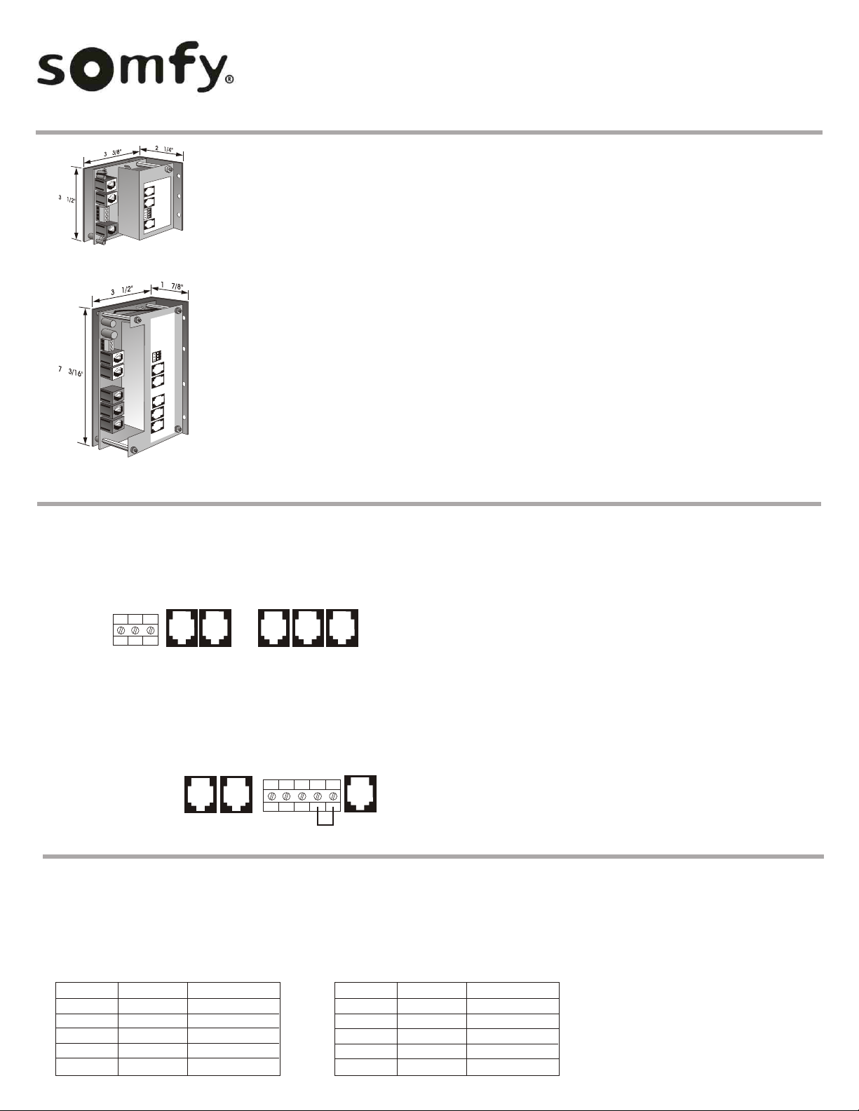
1. Individual ports (IND) control only one output. The Decorator
IGC Switch connects to the control via 6 conductor modular
cable.
2. A switch connected to the Master ports (MAS) operates all the
motors on the control board as a group. This port can also be
used to connect a number of IGCs or IGC/3N1s together to form
a group.
3. For group only control from an external device, low voltage
terminals have been provided on both the single IGC and
IGC/3N1. A momentary contact between the MAS UP and
COMMON terminals will activate the Master Up command.
Similarly, connecting the MAS DWN and COMMON terminals will
activate the Master Down command.
4. SINGLE IGC ONLY: The N-C (normally closed) INPUT terminal
is for a normally closed contact connected to a casement
window or french door. When the door or window opens, this
contact opens and disables the down direction. DO NOT
REMOVE FACTORY INSTALLED JUMPER IF THIS FEATURE IS
NOT USED.
LINE VOLTAGE CONNECTIONS
Connect Motor & Power Cables to the IGC & IGC/3N1 according to the wiring charts below.
Line Voltage installation must comply with local and NEC codes.
IGC
POWER
BLACK
WHITE
GREEN
MOTOR
WHITE
GREEN
RED
BLACK
IGC
BLACK
WHITE
GREEN
RED
BROWN
IGC/3N1
POWER
BLACK
WHITE
GREEN
MOTOR
WHITE
GREEN
RED
BLACK
IGC/3N1
BLACK
WHITE
GREEN
RED
BROWN
Note: An additional wire can
be provided on the IGC for
dry contact output capability.
Please contact customer
service for more information.
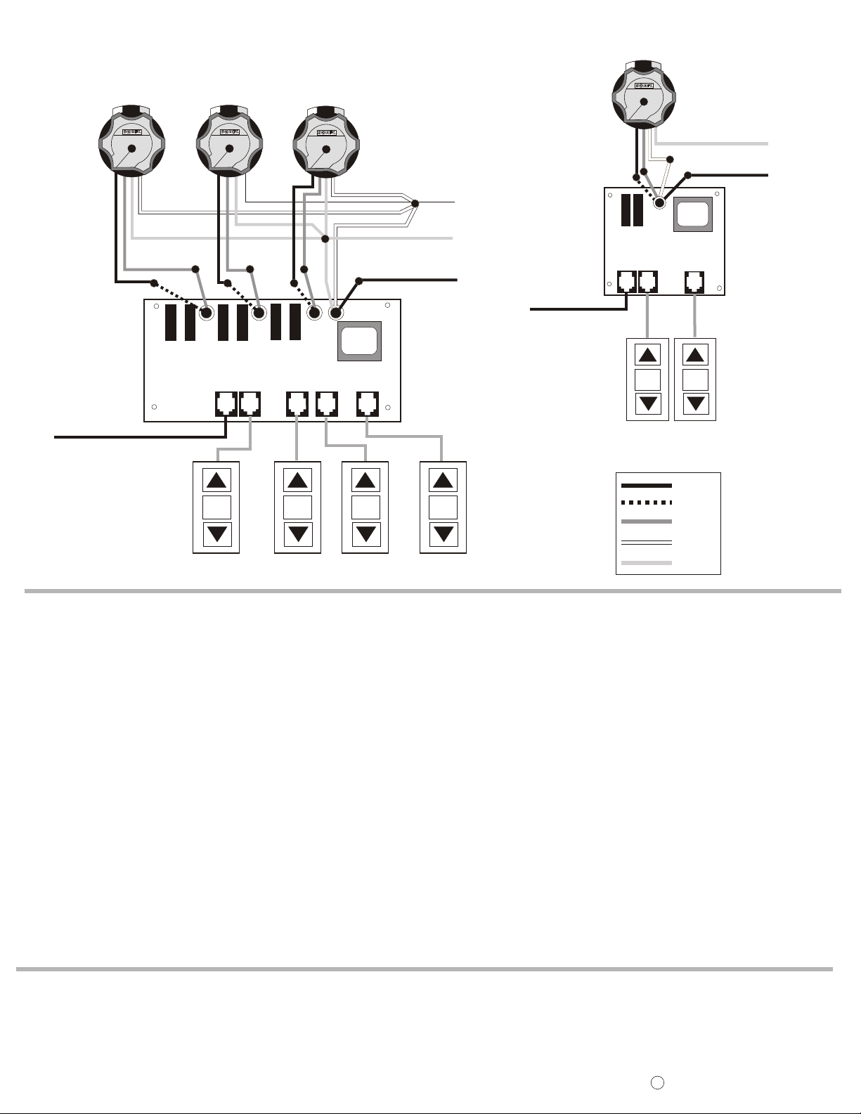
WIRING SCHEMATICS
IGC/3N1
TO NEXT IGC
RR RR
IGC/3N1
M M
STOPSTOP STOPSTOP STOPSTOP STOPSTOP
IND.
RR
IND. IND.
MOTORS
NEUTRAL
GROUND
HOT
IGC
TO NEXT IGC
RR
IGC
M M
STOPSTOP STOPSTOP
COLOR CODE
BLACK
BROWN
RED
WHITE
GREEN
MOTOR
GROUND
NEUTRAL
HOT
IND.
OPERATING INSTRUCTIONS
A. System Power Up
1.
With power off, wire IGC or IGC/3N1 as indicated above. Turn
all circuit breakers on (Note: motors should not move).
2. Pressing the DOWN arrow on the IGC Switch should move the
window covering down or out. If the direction is correct,
proceed to the next individual switch and repeat.
3. If the direction is not correct, turn off circuit breakers and
reverse the red and black wires at the appropriate motor and
repeat step 2.
B. Individual Motor Operation
1. A single motor can be controlled from its corresponding
individual switch. To activate either direction, momentarily
depress the button corresponding to the desired direction.
2. If the window covering is in motion, a STOP command can be
SOMFY CANADA
6315 Shawson Drive, Unit #1
Mississauga, Ontario L5T1J2
SOMFY SYSTEMS, INC.
47 Commerce Drive
Cranbury, NJ 08512
given by activating the direction of movement. For example, if
the treatment is moving up, activating another UP command
within 3 minutes will stop the window treatment. Alternately, it
can be stopped in any position by depressing the stop button on
the IGC Switch.
C. Group Operation
1. All motors on an IGC/3N1 can be operated as a group from an
IGC Switch connected to the Master Port. For multiple IGCs in a
system, connect one Master Port to the next.
2. A low voltage terminal block is provided for group control from
an external device such as home automation, lighting or other
system.
3. Direction and stop commands are the same as for Individual
Ports.
SOMFY MEXICO S.A. De C.V.
Calle 3 No.47, Loc.E-5
Fracc Ind. Alce Blanco
Nau.,Edo. de Mex C.P. 53370,Mex
SOMFY SYSTEMS, INC. reserves the right to change,
update or improve this document without prior notice.
Ref. No: 2500769 Rev. C
C
SOMFY SYSTEMS, INC. 4/02
 Loading...