

Page 1
FTS INSTALLATION
INSTRUCTIONS
Ref.900156D
r 1. INTRODUCTION.
..-
È
TL
U)
o
€)
J
o
=
3
o
=
a
0)
f
d
c)
d
.E
!
q)
c
G
-
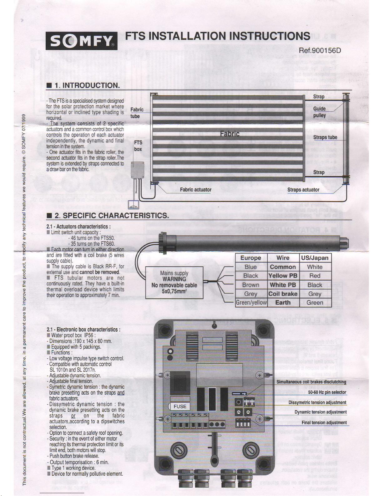
The FIS is
a
Eærallsed
system dæigned
for
the solar
protection
market
where
horizontal
or
inclined
type shading
is
reourreo.
..-
Tie-system,csnsislgof
I
specifig'
actuators
and a
common æntrol box which
controls
the ooeration of each actuator
independenlly, the dynamic
and
final
tension
in
tn sy$em.
-
One actuator fiS in he fahic roller,
tp
sæond actuator
fib in
tp stæ
rdb.Ttp
system
is
extended by stap ænnæled to
a draw bar on the fabric.
r 2.
SPECIFIC CHARACTERISTICS.
I
+i
o
l
q)
€
c)
.E
o
q)
(s
o
c
o
c
(É
E
Q)
o-
(É
.c
o,
E
c
(d
(d
!
o
È
=
(g
o
(t
c)
=
r
l
G
E
o
o
o
c
.9.
c
0)
E
f
.0
E
F
2.1
-
Aciuators
characterislics :
I
Limit
switch unit æpacity
:
-
46
tums on the
FIS50.
-
35 tums on the
ffS60.
with
a coil
brake
(5
wires
supply cable).
I The
supply cable
is
Black RR-F.
for
external use and ænnol be
removed.
I
FTS
tubular
motors
are
nol
continuously
rated. Tïey have
a fuill-in
thermal overload device
which limits
their operation to approximately
7 min.
2.1 - Eleclronic box characleristics :
ffi Water
oroof box
lP56 :
-
Dimensions :1
90
x 145 x
80
mm.
ffi Equipped
with
5
packings.
ffi Functions :
-
Low voltage impulse
type switch control.
-
Comoatible
with
automatic control
SL 1 01 0n and SL 201 7n.
-
Adiustable dynamic tension.
-
Adjustable
final
tension.
-
Symetric dynamic tension : the dynamic
brake
presetÏing
acts on the straps
and
fabric actuators.
-
Dissymetric
dynamic tension : the
dynamic brake
presetting
acts on the
straps or on the
fabric
actuators,according to a dipswitches
selection.
-
0ption to connect
a salety roof
opening.
-
Securitv
: in
the event oT either
motor
reachirig its
thermal
prolection
limil
or
its
limit
end, both
motors will
stop.
-
Push
button brake
release.
-
Output temporisation : 6
min.
e
Type 1 working device.
X Device for normally
pollutive
element.
lilains
supply
wARlill{G
No
æmovabb cable
5x0,75mrf
Europe Wire
US/Japan
Blue Common White
Black
Yellow
PB Red
Brown White PB Black
Grey Doil brake Grey
ireenffellou
Earth
Green
Simultaæous coil brakes
50-60
Hz
tension
tension
Final tension
Page 2
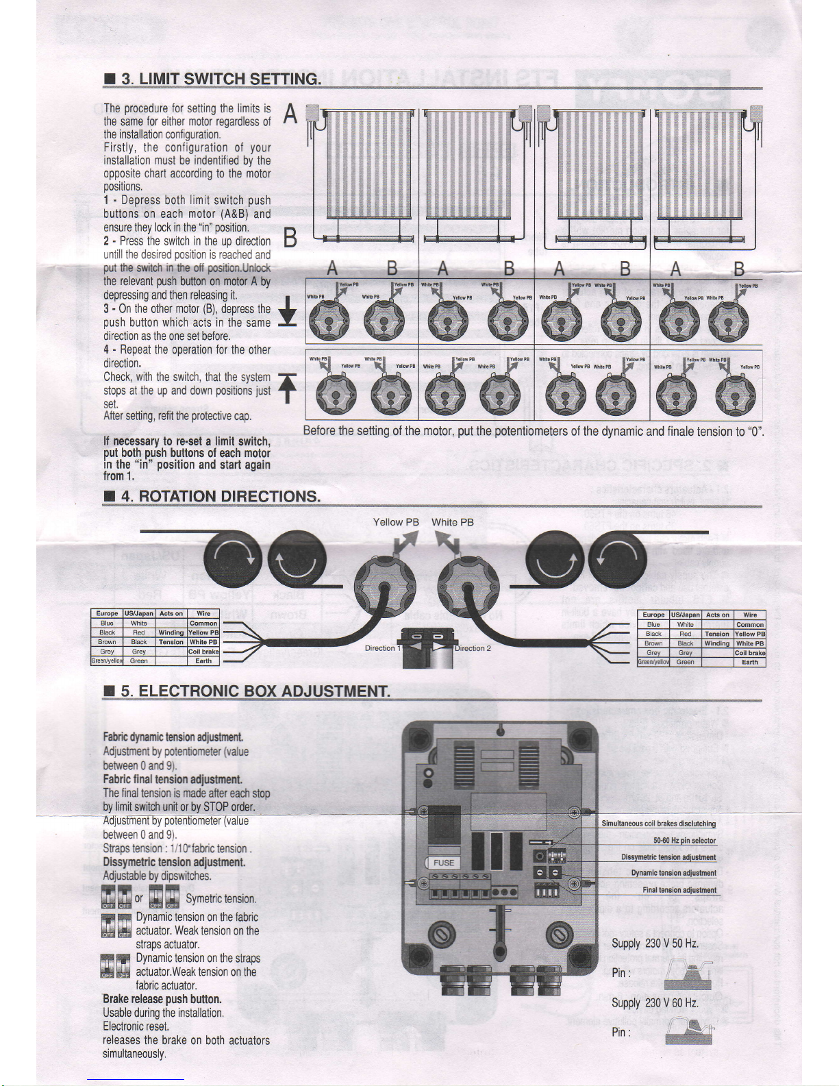
The
procedure
for
setting
the
limits is
the same
for
either
motor regardless
of
lhe installation
conf
iguration.
Firstly,
the configuration of
your
installation
must be indentified
by lhe
opposite chart according
to the
motor
positions.
1 - Depress
both
limit
switch
push
buttons on each
motor
(A&B)
and
ensure they lock in
lhe
"in" position.
2 - Press
the switch in
the up direction
untill the desired
position
is reached
and
put
the slvrtch
in
the off
posibon.Unlodr
the
relevant
push
button on motor A
by
depressing and then
releasing it.
3 - 0n the other
motor
(B),
depress
the
push
button which
acts
in
the same
direction as lhe one set before
4 - Repeat
the operation
for
the
other
direction,
Check,
with
the
switch,
that the system
stops at lhe up and down
positions
just
set.
After
setting,
refit
the
protective
cap.
lf necessary
to
re-set
a
limit
switch,
put
both
push
buttons
of each
motor
in
the
"iri" position
and start again
from 1.
r 4. ROTATION DIRECTIONS.
A;J
B
*
I
ffi
A B
A B
W
A
B A B
W"
@-w'
w"w@W
WNhèPBI WhfuPBI
\l
:** \
"'*m
@@
tYdlowP8 lYèrlowPB
**:
It
www
ly'
@@
snePBl
lYello{PB
{
"u**
*n'nru
IrÉ
,,q ,H\
rEt
TiST
***
llfl'"
*\
*u**
@@
Before
the setting
of the
motor,
put
the
potentiometers
of the dynamic and finale
tension to
"0".
Yellow PB
White PB
-3Q-
ofl
r
5.
ELECTRONIC
BOX ADJUSTMENT.
Fahh
dynamic tension adjustnent
Adjustmenl
by
polentiometer
(value
between 0 and 9I.
Fabric final
tension
adjusfnent
The final
tension
is made
after
each stop
by
limit
switch unit
or by STOP order.
Adjuslmfifty
poiêntkimeGr
(ùâlue
--
between
0 and 9).
Straps tension :
1;1
0'fabric tension
.
Dissymetric
lension adjustment.
Adjustable
by dipswitches.
rr iiltt
H#bi#
0r
HH#
symermc
tensron.
Dynamic
tension on the fabric
actualor. Weak
tension on the
straps actuator.
Dynamic
tension on the
straps
actuator.Weak tension on
the
fabric
actuator.
Brake
release
push
button.
Usable during the installation.
Electronic
resel.
releases
the
brake on both actuators
simultaneouslv.
SFil
H,çH#
F!'l!il!
ËHM
Simultaneous coil
Supply
Pin :
230 V
50
Hz.
Supply 230 V
60
Hz.
Pin :
Page 3

r
6. CONTROL BOX
CONNECTIONS.
-
The
commons wire
(blue)
from
both
actuators
are connected 1o
terminal 3.
-
The
earth wire
(yellow/green)
from
both actualors
must
be
connected lo
the
supply earth using a
connector
block.
-
An impulse
type
switch can
be
connected
to terminals
10,1
1
and
12.
-
lT no
safety device is fitted,
then
bridge
terminals
10
and 13
(done
in
Tactory).
iôt
BuÏ'Thd
attuator supply
and the security control cables
together in
the same slive.
r 7. INSTALLATION
PROCEDURE.
lc
i lO
i iE
I tÉ
I to
I t:
-*El-Ë
gRç
o_2,<
1 - Ensure
the correct size of
motors has
been selected
by
using the Somfy FfS
sdector
chart.
2 - Fit
the actuators
into
the tube with
the conecl drive adapters in
accordance with
our standard
installation instruclions.
3
-
depress both
limit
switch unil
push
buttons and ensure
they
lock in
the
"in'position.
4 - Mount
the motorised
barrels onto
uref
respeuuve
stop
ring re1.910002
must
be
Dynamic tension
with
the
motor
end
bracket.Ensure
thal both banels are
parallel.
5 - Attach
the
fabric
to the
lube.Connect the
test
lead
ref.137080
to the motor
as shown
and wind
the
labric
around the
tube. Set the
"in"
limit
by
releasing
the
relevant
push
button.
6
-
Fit
the
pulleys
and straps.Adjust
the straps as
required
to
ensure
that thev are
all the same
lenglh.Cdnnect
the test lead
to
molor
as shown
and
wind
the
straps around the
tube.Set the
"out"
limit
by
releasing
the relevant
button.
7-Before
connecting the actuators
and the
switch to the control box
set the
2
potentiometers
to "0"
and ensure that all the dioswitches
are
in
the'up"position.Connect
the
actualors and switch to the control
box as shown.
8 - Check that the system operates in
the conect sense and ensure that
the
limits have
been set conectly.
9 - Set the dynamic and final
lension
in
lhe system by
gradually
increasing
the settings on the
potentiometers.When
setting the
final
tension
in
the system, care
should be taken to
ensure lhat the
fabric
and all
fixtures
and fittinos
are capable of withsanding
tËe
operating
load.
1O-lf
the straps have to be adjusted,
press
the brake
release
button in
ihe control box, adjust the straps
as
necessary
and then operale the
system as normal.
For 2 heads
on the left
and
fabric
and straps above winding
Page 4

FTS WITTIONE
CONTROL
POINT
2 motor heads on the right. Fabric and straps above winding
WARNING
I Do not forget to connecl the eanh wirês,
IThe
wires section is depending on the
number and the Ëted
power
ol
the
aduarore
Oblique : US
wiring
For 2
heads
on the
right
and
fabric
and straps above
winding
FTS WITH
ONE CONTROL
POINT
2 motor heads on the right. Fabric and
straps
above winding
ËÈp.9Èæ,9
ffi
e
ilililil1
TTTÏTI-| I I
#ËËÊ#.sËEs
5 core cable
lndividual
control switch
\
o
o
=
o
\^
Y
E
E
o-
o
=
o
WARNING
lYou
hâve to identilicate the ^andv
direction ol each aduato6.
a Do not forget to connd the eadh wires,
lThe wires section is depending on the
number and the rated
power
of lhe
aclualo6.
I
Cables atter
installation must not ooerate
trâction on the têminals
Oblique : US wiring
 Loading...