

SOMFY Freevia 280,Freevia 300 Operating And Installation Manual
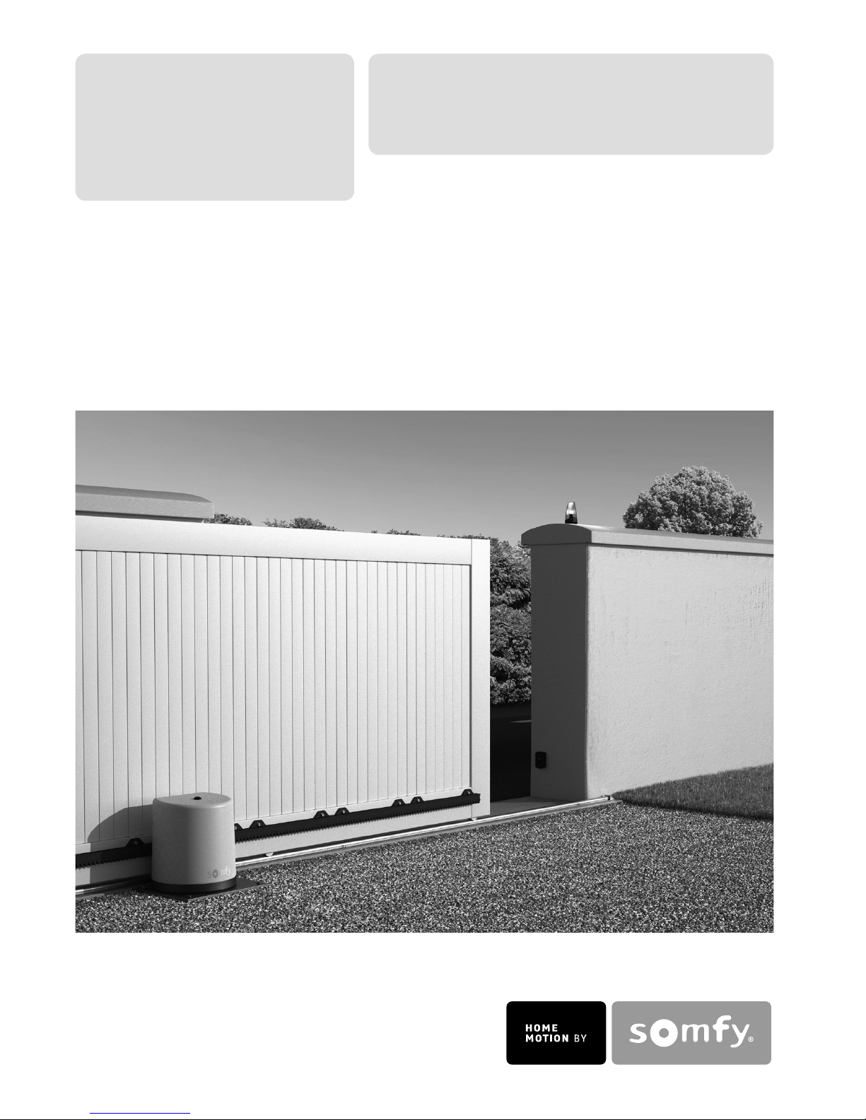
Freevia 280
Freevia 300
Operating and installation guide
Instrukcja montażu i obsługi
5057966C
FreeVia 280
+
FreeVia 300
8
14
17
15
16
6
11
9
9
8
12
20
10
3
7
21
22
18
1
2
5
4
13
19

1
EN
TABLE OF CONTENTS
WELCOME .........................................................................................2
Who are Somfy? 2
Assistance 2
SAFETY INSTRUCTIONS .................................................................2
PRODUCT DESCRIPTION ................................................................3
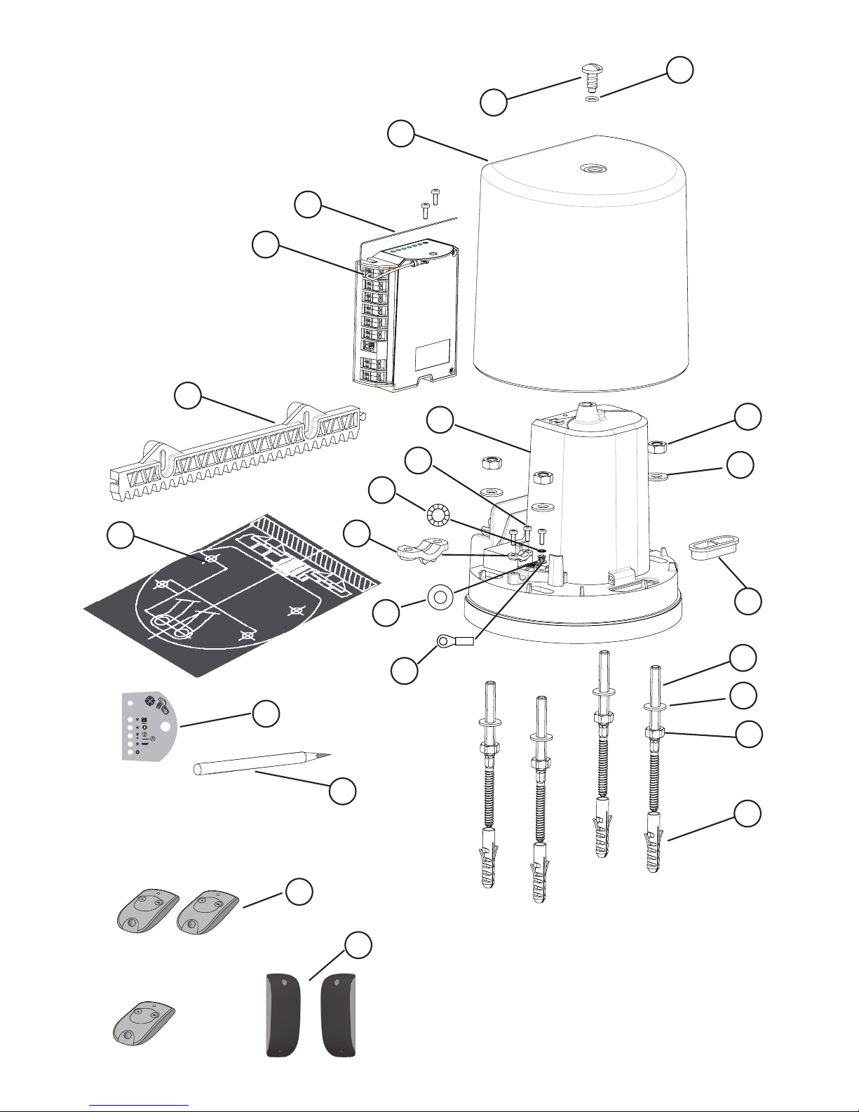
Composition of the kit 3
Maximum weight and dimensions of the gate 4
Motor dimensions 4
General view of the installation 5
Technical specications 5
PRELIMINARY OPERATIONS ..........................................................6
Pre-installation checks 6
Tools required 6
Electrical preequipment 7
Safety instructions 7
1. PREPARING THE BASE ...............................................................8
2. MOUNTING ....................................................................................9
3. ELECTRICAL CONNECTIONS ...................................................12
4. QUICK COMMISSIONING ...........................................................14
5. FITTING THE COVER .................................................................15
OPERATION ....................................................................................16
Operation in sequential mode 16
Operation in automatic mode 17
Obstacle detection operation 17
Area lighting operation 17
Operation of the 3 button control points or remote controls 18
Unlocking/locking the motor 18
ADVANCED PARAMETER SETTING .............................................19
Selecting the buttons of your 2 or 4 button remote control 19
Memorising a 2 or 4 button remote control 19
Memorising a 3 button remote control 19
Activating pedestrian opening 20
Activating AUTO CLOSE mode 20
ACCESSORIES ...............................................................................21
SOLAR POWER ..............................................................................29
TROUBLESHOOTING GUIDE .........................................................30

2
EN
WELCOME
Thank you for choosing a Somfy product. This equipment has been designed, manufactured
and distributed by Somfy in accordance with a quality policy complying with the ISO 9001
standard.
Who are Somfy?
Somfy develops, manufactures and sells automatic control devices for domestic opening
and closing systems. We offer alarm systems, automatic control devices for awnings, roller
shutters, garages and gates. We guarantee all Somfy products will meet your expectations in
terms of safety, comfort and time saving on a daily basis.
At Somfy, the pursuit of quality is a continuous process of improvement. Somfy's reputation
has been built upon the reliability of its products and the Somfy brand is synonymous with
innovation and technological expertise worldwide.
This product fully complies with the essential safety guidelines and specications set out by the
directive according to the EN 60335-2-103 standard.
Assistance
Getting to know our customers, listening to them, meeting their needs: this is Somfy’s approach.
For further information on how to choose, purchase or install Somfy systems, please ask for
advice at your DIY store or contact a Somfy advisor directly for help and assistance.
Somfy UK Hotline : 0113 391 30 30
Internet: www.somfy.com
SAFETY INSTRUCTIONS
Before installing your motor, carefully read all the instructions in this guide. All the instructions
given must be followed closely and this guide must be stored in a safe place throughout the
service life of your product.
Failure to follow these installation instructions may result in serious injury or damage to the
equipment. Somfy shall not be held liable in this event.
This device is not designed to be used by persons (including children) whose physical, sensory
or mental capacity is impaired, or persons with little experience or knowledge, unless they are
under supervision or have received instructions on using the device by a person responsible
for their safety.
Do not allow children to play with the xed control devices.
Remote controls must be placed out of sight and out of reach.
If you are using a switch without a locking device***, ensure that other people remain at a
distance.
Frequently check the product to detect any defects in balance in the gate or any signs of wear.
Do not use the motor if it requires repair or adjustment.
Disconnect the supply motor during cleaning operations or other maintenance operations.
Before installing the motor, ensure that the driven part is in good mechanical condition, that it
is correctly balanced and that it opens and closes correctly.
Ensure that any danger zones (crushing, cutting, trapping) between the driven part and the
surrounding xed parts created by the opening of the driven part are avoided.
3
EN
Watch your gate while it is moving.
Any switch without a locking device*** must be in direct view of the driven part, but away from any
mobile parts. It must be installed at a minimum height of 1.5 m and must not be accessible to the
public, unless it is key-operated. Ensure that people remain at a distance when it is in use.
Maintain a clear area of 500 mm from the end of the gate when it is completely open.
After installation, ensure that the mechanism is correctly adjusted and that the protection
system and any manual release mechanism operate correctly.
Somfy declares that this product complies with the essential requirements and other relevant
provisions of Directive 1999/5/EC. A Declaration of Conformity is available at www.somfy.
com/ce. Product can be used in the European Union and Switzerland.
*** example: interphone, key lock, code keypad...
PRODUCT DESCRIPTION
This motor is designed for sliding doors on individual residential properties.
Composition of the kit
No. Description Quantity
1 Cover 1
2 Aerial 1
3 Electronic unit 1
4 Motor 1
5 Cover screw 1
6 O-ring (9 x 2) 1
7 Rack (33 cm) 12
8 Galvanised screw (M10) 8
9
Galvanised medium plain washer (10.5 x 22 x
2)
8
10 Cable grommet 1
11 Dual thread lag screws (M10 x 15) 4
12 Plug (12 x 60 S12) 4
13 Galvanised TCB self-tapping screw (M4 x 12) 3
14 Serrated washer (AZ4) 1
15 Cable clip 1
16 Medium plain washer (M4 x 10) 1
17 Insulated round terminal (D4) 1
18
Installation template to be cut out (printed on
card)
1
19 Electronic unit label 1
20 Pencil 1
21 Keytis NS 2 RTS remote control 1/2
Only in the FreeVia 300 kit
22 Set of photoelectric cells 1
Do not throw away your scrapped equipment or used batteries with household waste.
It is your responsibility to dispose of your electronic equipment in the relevant recycling
points.
4
EN
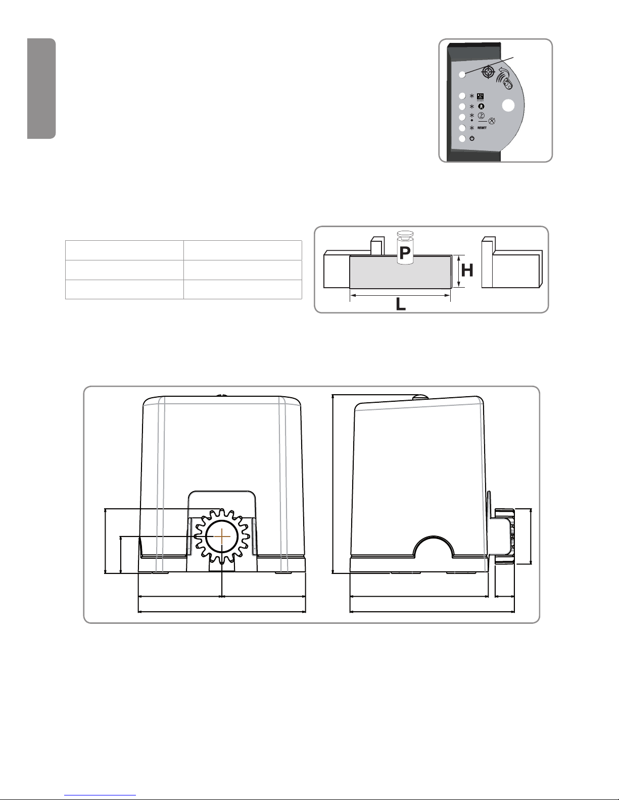
Maximum weight and dimensions of the gate
Max. weight (W) 300 kg
Max. height. (H) 2 m
Max. width. (W) 5 m
Size of motor (in mm)
Ambient light detector
The motor's electronic unit is tted with an ambient light detector
which detects whether or not the cover is tted. This means that
settings mode is only available when the cover is removed. If the
cover is tted, the motor is in standby mode.
84
72
232
48
109
218 214
109
180
25
Light
sensor
5
EN
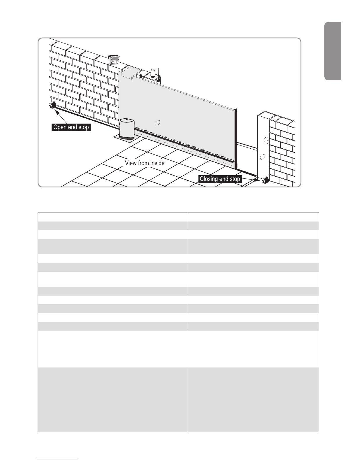
General view of the installation
Technical data
Supply voltage ~ 230 V/Solar
Motor type 24 Vdc
Motor output 150 W
Max. power consumed
(with area lighting)
600 W
Standby consumption 4.5 W
Average frequency of movements per day 20 cycles/day
Opening speed*
3 m in 16 seconds, excluding slow zone
(20 cm)
Automatic obstacle detection Compliant with standard EN 12 453
Operating temperature - 20°C to + 60°C
Thermal protection Yes
Protection rating IP 44
Integrated radio receiver Yes
Remote controls:
Radio frequency
Range in eld of use
Storage quantity
433.42 MHz
~50 m
16
Possible connections:
Output for orange light
Area lighting output, contact supplied
Accessories supply output
Backup battery input
Photoelectric cell input
Dry contact control input
Flashing, 24 V, 10 W
500 W max. (~ 230 V)
24 V - 15 W max, 230V only
Yes
Yes (BUS)
Yes, 230V only
* The opening time varies according to the gate specications.
6
EN
Pre-installation checks
Checking your gate ►
Your gate must be in good condition: ensure that its structure is suitable for automatic
control and that it conforms to the relevant standards.
Your gate must remain horizontal throughout its travel, and must open and close
manually with ease. Ensure that the gate travels straight at ground level, and that there
are no sticking points that may prevent it from sliding correctly.
Types of gates which can be motorised ►
Your motor can be adapted to all types of sliding door (PVC, wood, metal etc.).
For a barred gate with bars spaced
more than 50 mm apart, it is essential
to install a mesh (40 x 40 mm type)
along the entire length of the gate.
This will prevent any risk of trapping
(see mark ‘C’ opposite).
Fitting end stops to the gate ►
The gate must be stopped by end stops
xed securely to the ground to delimit the travel of the gate on opening and closing.
Tools required
C
PRELIMINARY OPERATIONS
17
12

7
EN
Electrical preequipment
Ensure that you have an Orange ICT Ø 25 mm protective sheath for underground
cabling. If a cable conduit cannot be made, use a cable grommet which will
withstand the passage of vehicles (ref. 2400484).
Power supply (230 V only) ►
Fit a 230 V electrical input as close as possible to the motor.
The motor's electronic unit must be supplied with 230 V - 50 Hz with a exible 1.5 mm²
cable.
The electric line should be:
Exclusively reserved for the motor.•
Fitted with protection: •
– a 10 A fuse or breaker,
– a differential type device (30 mA).
Installed according to current electrical safety standards in the countries in which •
it is used.
An all-pole supply cut-off device must be provided:
either by using a supply cable tted with a plug,•
or by using a switch ensuring a minimum separation distance between the contacts •
of 3 mm on each pole (according to the EN 60335-1 standard).
It is recommended that you t a lightning conductor (max. residual voltage 2 kV).
The cells (as an option in the Freevia 280 pack) ►
The cells are essential for operation in automatic mode and for opening in public
areas.
Cell wiring • (see page 23)
Ensure that there is a sheathed connection between the two pillars for the cell wiring.
Drill holes in the two ends of the gate frame to feed through the sheaths. The cells
must be connected to the motor electronics using a 2 x 0.75 mm² cable. The feed
wires should arrive under the cells.
Cell location (see page 22).•
Orange light (optional) ►
It is recommended that you install an orange light for operation in automatic mode and
for opening in public areas.
Orange light wiring (see page 26) •
Allow the cable to be fed through for the installation of the orange light. The orange
light must be connected to the motor electronics using a 2 x 0.75 mm² cable.
Orange light location (see page 25)•
Safety instructions
The safety instructions must be followed throughout the installation:
Remove any jewellery (bracelets, chains, etc.) during installation.•
For drilling or welding operations, wear special goggles and sufcient protection.•
Use appropriate tools, specied on page 6.•
Be careful when handling the motorisation system to prevent any risk of injury.•
Do not connect the unit to the power supply or to the backup battery (optional) before the •
installation process is complete.
Never use high pressure cleaning equipment.•
8
EN
Fitting the end stops ►
The gate must be stopped by end stops which are securely xed to the ground and which
delimit the end of travel.
Base ►
The lag screws for mounting the
motor must be securely anchored to
the ground. The type and dimension
of the base depends on the nature
of the ground. Allow for the supply
cable to be fed through according to
the electrical standards in force in
the country of use.
1. PREPARING THE BASE
Steps
Positioning the motor•
Fitting the end stops•
Base•
Positioning the motor ►
Horizontal position
Ensure that the motor is always positioned in the eld of the gate when opening and closing.
Vertical position
Ensure that the motor
is raised off the ground
slightly (over 20 mm).
Rack
min. 250 mm
min. 200 mm
Gate
Base
Base
Gate
cable feed

9
EN
Mounting the motor ►
[1]. Tighten the 4 nuts (8) and add 4 washers (9).
[2]. Remove the cover (1) from the motor (4).
[3]. Position the motor on the
lag screws: ensure that
the bracket (base of the
motor) is no more than
25 mm above the ground.
The recommended space is
between 20 and 25 mm.
Use a spirit level to
check that the motor is level.
[4]. Once the motor is positioned at the right height
in relation to the ground, x it in place using the
washers (9) and tighten the 4 nuts (8).
[5]. Position the pre-drilled grommet (10) in the
opening through which the supply cable
should be fed.
Steps
Fitting the lag screws•
Mounting the motor•
Fitting the rack•
Mechanical adjustment•
Fitting the lag screws ►
[1]. Position the installation template (18) on the
ground and drill 4 holes using a drill bit (Ø
12 mm) suitable for the type of ground.
[2]. Insert the plugs (12). Screw in the lag
screws (11).
2. MOUNTING
Grease the lag screws lightly before
screwing them into the plugs.
10
EN
Fitting the rack ►
77
1
2
3
[1]. Check that the motor is
unlocked and that the
handle is in position
.
[2]. Use the pencil provided
(20) to mark the
position of the rack.
With one hand, hold
the pencil in the
notches provided on the
motor.
With the other hand, slide
the gate to trace the height
of the rack mounting.
[3]. Fix an initial rack component
(7) by positioning the top
of the rack on the line
drawn by the pencil.
Fix the other rack
components in the same
way. Use HSHC head
screws (ø 6) to suit the gate
material (metal, wood).
Up to 5 m of rack can be installed (set of 3 x 33 cm rack components, ref: 2400962).
 Loading...