

SOMFY Elixo 500 230 V Installation Manual
somfy.com
Elixo 500 230 V
EN
Installation manual
ES
Manual de instalación
PT
Manual de instalação
EL
Εγχειρίδιο εγκατάστασης
5054409A


Elixo 500 230 V
CONTENTS
GENERAL INFORMATION 2
SAFETY 2
General information 2
Safety instructions 2
PRODUCT DESCRIPTION 3
Composition of the kit 3
Description of the motorisation 3
General motor size 3
Area of application 4
General view of a standard installation 4
INSTALLATION 4
Assembling the release lever 4
Disengaging the motorisation 4
Installing the motorisation 5
Wiring 6
QUICK COMMISSIONING 7
Memorising the remote controls 7
Setting the motor torque 7
MOTORISATION OPERATION 8
CONNECTING ADDITIONAL DEVICES 8
230 V integrated fl ashing amber light 8
Photoelectric cells 8
Electric eye 8
Wired keypad 8
Wired keyswitch 9
EN
PARAMETER SETTING 9
CLEARING THE REMOTE CONTROLS 10
DIAGNOSTICS 10
TECHNICAL DATA 10
Copyright © 2008 Somfy SAS. All rights reserved. 1

Elixo 500 230 V
GENERAL INFORMATION
This product, installed in accordance with this guide, complies with EN 12453 and EN 13241-1 standards.
Hereby, Somfy, declares that this product is in compliance with the essential requirements and other relevant provisions
EN
of Directive 1999/5/EC. A declaration of conformity is available on the website at www.somfy.com/ce (Elixo 500 230V),
usable in EU, CH and NO.
SAFETY
General information
Always read this installation guide and the attached safety instructions before installing this Somfy product.
This Somfy product must be installed by a professional motorisation and home automation installer, for whom these
instructions are intended.
The use of any safety components not approved by Somfy remains the sole responsibility of the installer.
These instructions describe how to install, commission and operate this product.
Moreover, the installer must comply with current standards and legislation in the country in which the product is being
installed, and inform his customers of the conditions for use and maintenance for the product.
Any usage outside of applications defi ned by Somfy constitutes non-compliance, and is therefore not covered by
the guarantee. In this event, as for all usage not consistent with the instructions given herein, Somfy accepts no
responsibility for harm or damage.
Safety instructions
Before installation, ensure that the gate frame conforms to current standards, particularly:
The gate sliding rail must be straight and horizontal and the wheels must be able to support the weight of the gate.•
The gate should move easily over its entire travel distance and there should be no sign of excessive side sway.•
The upper guide should allow the gate exact clearance to ensure regular, silent movement.•
End stops must be installed on the ground at both the opening and closing stop positions.•
The position in which the motorisation mechanism will be fi tted must allow for safe and easy manual release. •
If after evaluation the gate system does not meet the conditions set out above, they must be repaired or, if necessary,
replaced.
The selected safety accessories for the installation must comply with the current standards and regulations in force in the
country in which the product is being installed.
Ensure that there are no danger zones (risk of crushing, cutting, trapping) between the gate and the surrounding fi xed
elements caused by the opening movement of the gate.
On a barred gate, if the bars are more than 40 mm apart, install an appropriate safety device to prevent cutting.
Maintain a clear area of 500 mm behind the gate when it is completely open.
Take care while the gate is moving.
Place the fi xed control devices and remote controls out of the reach of children.
Any switch without a locking device must be installed in direct view of the gate and away from any mobile parts. The
minimum height at which it must be installed is 1.5 m. It must not be accessible to the public.
During installation of the motorisation:
Remove any jewellery (bracelets, chains, etc.).•
For drilling and welding operations, wear special glasses and suffi cient protection.•
Use the appropriate tools.•
Do not connect to the mains or to a backup battery before installation is complete.•
Be careful when handling the motorisation system to prevent any risk of injury.•
In order to operate, the motorisation must be supplied with 230 V 50 Hz. The electric supply should:
solely be used for the motorisation,•
have a minimum cross section of•
be fi tted with an approved all-pole switch with contact openings of at least 3.5 mm, fi tted with a protection device •
(fuse or circuit breaker with a 16 A rating) and a differential device (30 mA),
be installed in accordance with the current electrical safety standards.•
It is recommended that the installation be fi tted with a lightning conductor (in compliance with standard NF C 61740,
maximum residual voltage 2 kV).
1.5 mm²,
2 Copyright © 2008 Somfy SAS. All rights reserved.
Elixo 500 230 V
Regularly check the condition of the gate. Gates in poor condition must be repaired, reinforced or even replaced. Check
that the various motorisation component’s screws and fi ttings are correctly tightened.
Before carrying out work on the installation, switch off the power supply.
PRODUCT DESCRIPTION
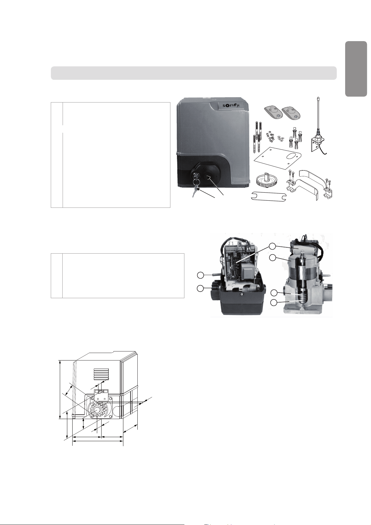
Contents of the standard kit
1 Elixo 230 V Motor x 1
2 Keytis 2 RTS remote control x 2
3 RTS 3 m offset aerial x 1
Ground mounting kit:
4a Lag screws x 4
4b Nut x 8
4c Washer x 4
4d Plug x 4
4e Base plate x 1
5 Manual release handle assembly x 1
6 Handle locking key x 2
7 End limit brackets x 2
8 Torque setting handle x 1
9 Spanner x 1
Description of the motorisation
1 Control unit and capacitor
2 Motor
3 Reduction unit with worm screws - helicoid drive wheel
4 Mechanical clutch on the motor shaft
5 End limit unit
6 Pinion with release mechanism
EN
1
5
6
5
6
2
4
a
4
b
4
c
4
d
4
e
8
7
3
9
1
2
3
4
General motor size
260
Øp56
122
Copyright © 2008 Somfy SAS. All rights reserved. 3
37
22
50
131
227
43
159
96
Elixo 500 230 V
E
E
D
C
F
G
A
B
C
E
E
D
F
G
i
i
H
Area of application
Sliding gates up to 500 kg and carrying out 100 operations per day.
In order to comply with standard EN 12453, an active edge sensor fi tted with autotest electronics (Bircher Reglomat
ref. ELE040/080A0J0/1/XXXX/2 + ref.ESA25-24ACDC) must be installed on the motorisation. After installing the active
edge sensor, it is essential that a stress test be carried out using measurement equipment which conforms to the requi-
EN
rements set out in clause 5.1.1 of standard EN 12445.
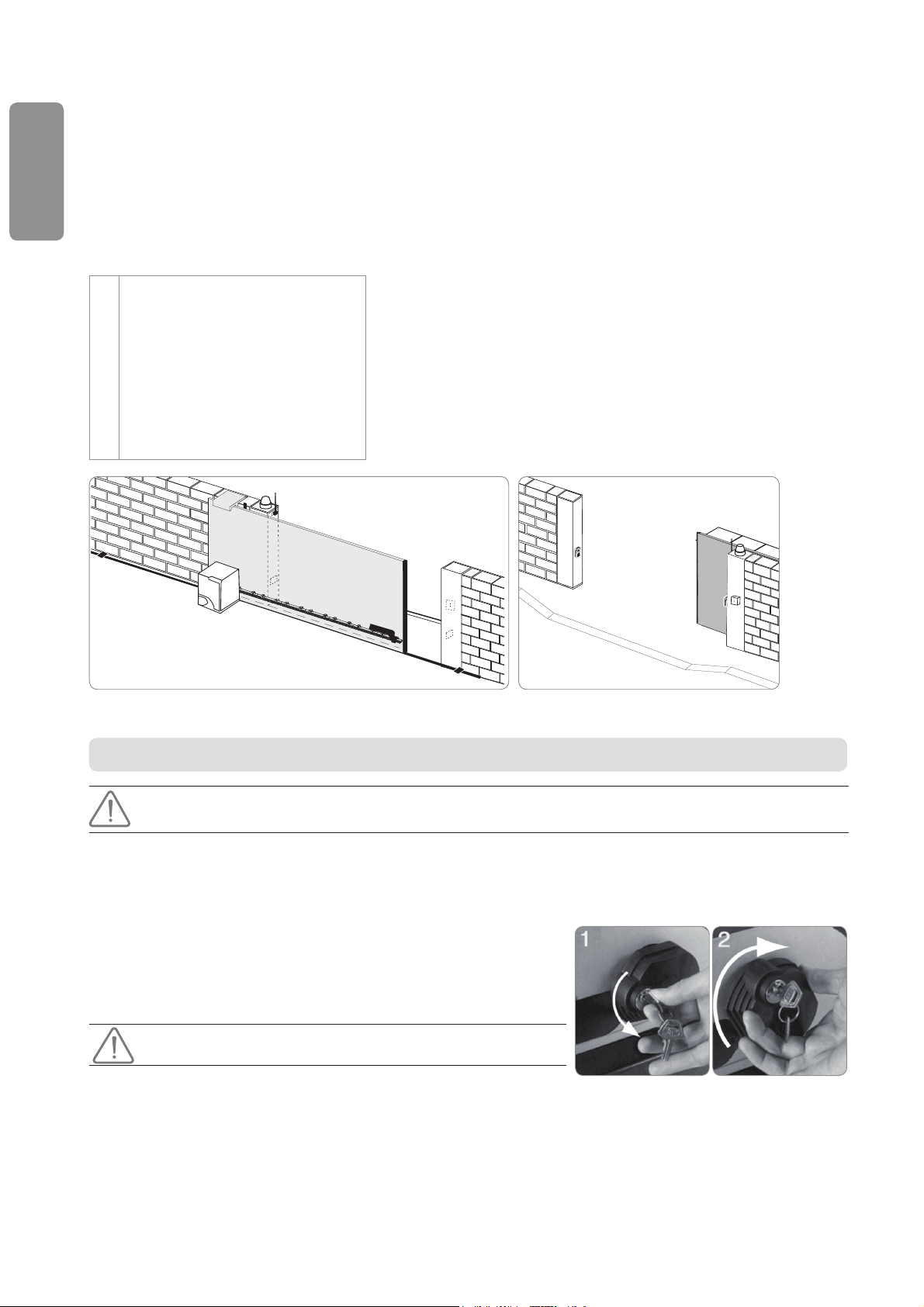
General view of a standard installation
A Motor
B Rack
C Aerial
D Orange light
E Set of photoelectric cells
F Key lock
G Active safety edge sensor
H End limit brackets
i End stops in the ground
INSTALLATION
The motorisation must be disengaged during installation.
Assembling the manual release handle
Insert the release handle into the specifi c housing on the motor.[1]
Tighten the release handle.[2]
Fit the screw cover.[3]
Disengaging the motorisation
Turn the key a quarter of a turn to the left. [1]
Turn the release handle to the right.[2]
Do not forcibly push the gate. Hold the gate over its entire travel
during manual manoeuvres.
4 Copyright © 2008 Somfy SAS. All rights reserved.
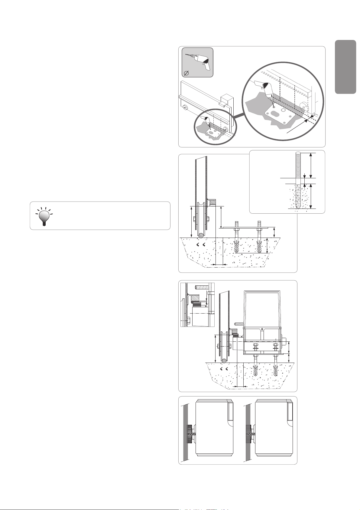
Installing the motorisation
25 mm
14 mm
h
25
>23
h100 130
85
77
h
25
50
>23
h100 130
2 mm
60 mm
20 mm
55 mm
100 mm<h<110 mm
110 mm<h<130 mm
NO OK
Fitting the mounting system
The motor mounting kit provided is to be used on a concrete
base. For all other types of mounting, use the appropriate
fi ttings.
Position the base plate:[1]
parallel to the gate,•
with the symbol on the pinion pointing towards the gate,•
by moving it by 25 mm in relation to the front line of the •
rack (if the rack is fi tted with a cover, measure from the
line on the rack, not on the cover),
so that it does not obstruct movement and to ensure the •
gate is able to open and close completely.
Mark the location for the ground mountings.[2]
Drill to a depth of 85mm.[3]
Insert the plugs.[4]
Tighten the lag screws on:[5]
the threaded section for a rack height of between 110 and •
130 mm,
the threaded section + the unthreaded section for a rack •
height of between 100 and 110 mm.
Elixo 500 230 V
EN
To facilitate tightening of the lag screws, use 2
nuts to form a “double nut”.
Screw a nut onto each lag screw.[6]
Place the base plate onto the lag screws with the symbol [7]
on the pinion pointing towards the gate. It must be a
minimum of 23 mm from the ground.
Mounting the motor
Position the motor on the lag screws, insert it and push it [1]
towards the gate.
Ensure the pinion is correctly positioned under the rack[2]
Set the height of the motor and/or the rack to ensure a [3]
clearance of approximately 2 mm between the rack and the
pinion. This setting is important to prevent premature wear
of the pinion and rack; the pinion must not be supporting
the weight of the gate.
Check:[4]
that the setting nuts all come into contact with the base of •
the motor,
the motor is level,•
the gate runs correctly,•
the clearance between the rack and pinion does not vary •
signifi cantly over the gate’s travel.
Fit a washer and nut onto each lag screw in order to fi t the [5]
motor.
Copyright © 2008 Somfy SAS. All rights reserved. 5
Elixo 500 230 V
5 mm
15 mm
a
b
181516
17
a
b
5
M
1
GND
2
3
4
N
L
DXSX
Fitting the end limit brackets
Manually move the gate to the open position.[1]
Position a bracket onto the rack so that it activates the motor end limit contact. [2]
Screw the bracket onto the rack.[3]
Manually move the gate to the closed position then repeat steps 2 and 3 to fi t [4]
EN
the second bracket to the rack.
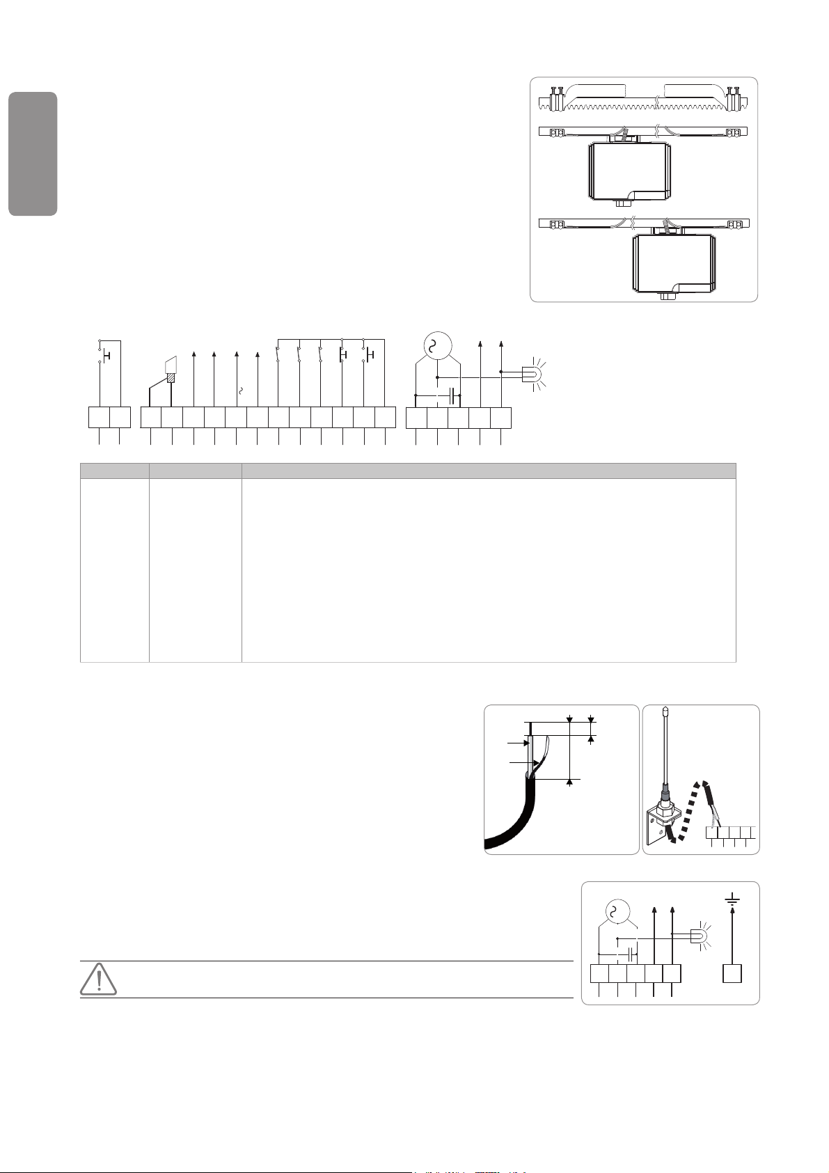
Wiring
General wiring diagram
PED
24V
NC
SWC
NCSTNO
PHOT
N
L
M
BL
COM
NC
NC
SWO
0V
20
Terminals Description Function
1 N Neutral single-phase 230 V~, 50-60 Hz power supply
2 L Live single-phase 230 V~, 50-60 Hz power supply
3-4-5 Motor connection (4 = shared, 3 and 5 = motor and capacitor)
1-4 230 V output, fl ashing orange light
7 COM Shared by control inputs (8-9-10-11-12)
8 START Control point input, sequential operation
9 STOP Control point input (closing only)
10 PHOT Photoelectric cell input
11 SWO Opening end limit contact
12 SWC Closing end limit contact
13-14 0V-24V~ Alternating 24 V output for power supply to the additional devices
15-16 Unused outputs
17 ANT Aerial core
18 ANT Aerial braid
19 COM Shared
20 PED Pedestrian opening control point input
19
18
17
16
141513
12
11
10
5
3
7
8
9
4
1
2
Aerial wiring
For optimum reception, the aerial must not be cut and must be as far away
as possible from the power supply terminal blocks and wires. The aerial
must always be installed at a height and must be visible from a distance.
Do not fi t the aerial to a metal post or behind a wire fence.
Cut the coaxial cable if it is too long. Shortening the cable will improve the
signal (a coaxial cable
insulating screw joint will distort the signal).
The mounting plate is an active component of the aerial. It must not be
removed or modifi ed.
which is too long, extended or connected with an
Connection to the power supply
To connect the motor to the power supply, use a standard multicore cable with a minimum
cross section of 3x1.5mm².
Inputs 9 and 10 must be bridged to terminal 7 if they are not used to connect a
safety device.
6 Copyright © 2008 Somfy SAS. All rights reserved.
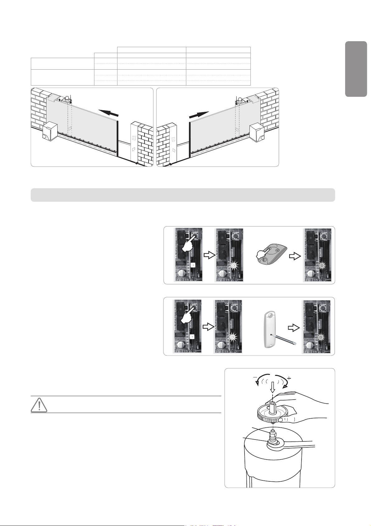
Checking the motorisation wiring
A
B
2 s
[1]
[2]
.......2 min........
2 s
[1]
[2]
.......2 min........
A
B
Elixo 500 230 V
Wire Terminal Terminal
Motorisation to the left (A) Motorisation to the right (B)
Motor connection Black 3 5
Brown 5 3
End limit connection Red 11 12
Brown 12 11
Black 7 7
Switch on the power to the installation before commissioning.
QUICK COMMISSIONING
Memorising the remote controls
To memorise a remote control:
Press the PROG button on the control unit for [1]
2 seconds. The red indicator light will come on.
Press a channel on the remote control to which [2]
the motorisation will be linked within 2 minutes.
The red indicator light fl ashes, the remote control
has been memorised.
If this procedure is carried out using a channel which
has already been memorised, this channel will be
cleared.
To add other remote controls: repeat the above
procedure.
To add a Telis type remote control:
Press the PROG button on the control unit for [1]
2 seconds. The red indicator light will come on.
Press the PROG button on the back of the Telis. [2]
This must be done within 2 minutes. The red
indicator light fl ashes, the remote control has
been memorised.
To exit programming mode without programming a
remote control: briefl y press the PROG button on the
control unit.
EN
Setting the motor torque
The motor torque must be set in accordance with current safety
standards before operating the motorisation.
[1] Turn off the power supply.
[2] Using the spanner provided, lock the motor shaft “A”.
[3] Using the torque setting handle, tighten the automatic tightening nut “B” to
increase the torque or loosen it to reduce the torque.
AT THIS STAGE IN THE INSTALLATION, THE MOTORISATION IS OPERATIONAL.
Copyright © 2008 Somfy SAS. All rights reserved. 7
Elixo 500 230 V
5
M
1
234
N
L
24V
ac/dc
0V C NC NO
12345
12
24V
ac/dc
0V
CR
CE
24V
IIß RC
0V
BL
NC
PHOT
COM
NCSTNO
18
7
NC
SWCNCSWO
8
9
11
12
141513
10
16
17
24V
IIß RC
0V
BL
NC
PHOT
NCSTNO
7
NC
SWC
COM
NC
SWO
8
9
11
12
141513
10
16
T1
C1 R1 V
R3
T2 C2 R2
T3 C3
H
P2
M
P1+HE – V
}
}
7 s
24V
0V
19
20
STOPNCPHOT
NC
START
COM
NO
7
NC
SWO
SWC
NC
PED
8
9
11
12
14
13
10
MOTORISATION OPERATION
See pages 2 to 3 in the user’s manual.
EN
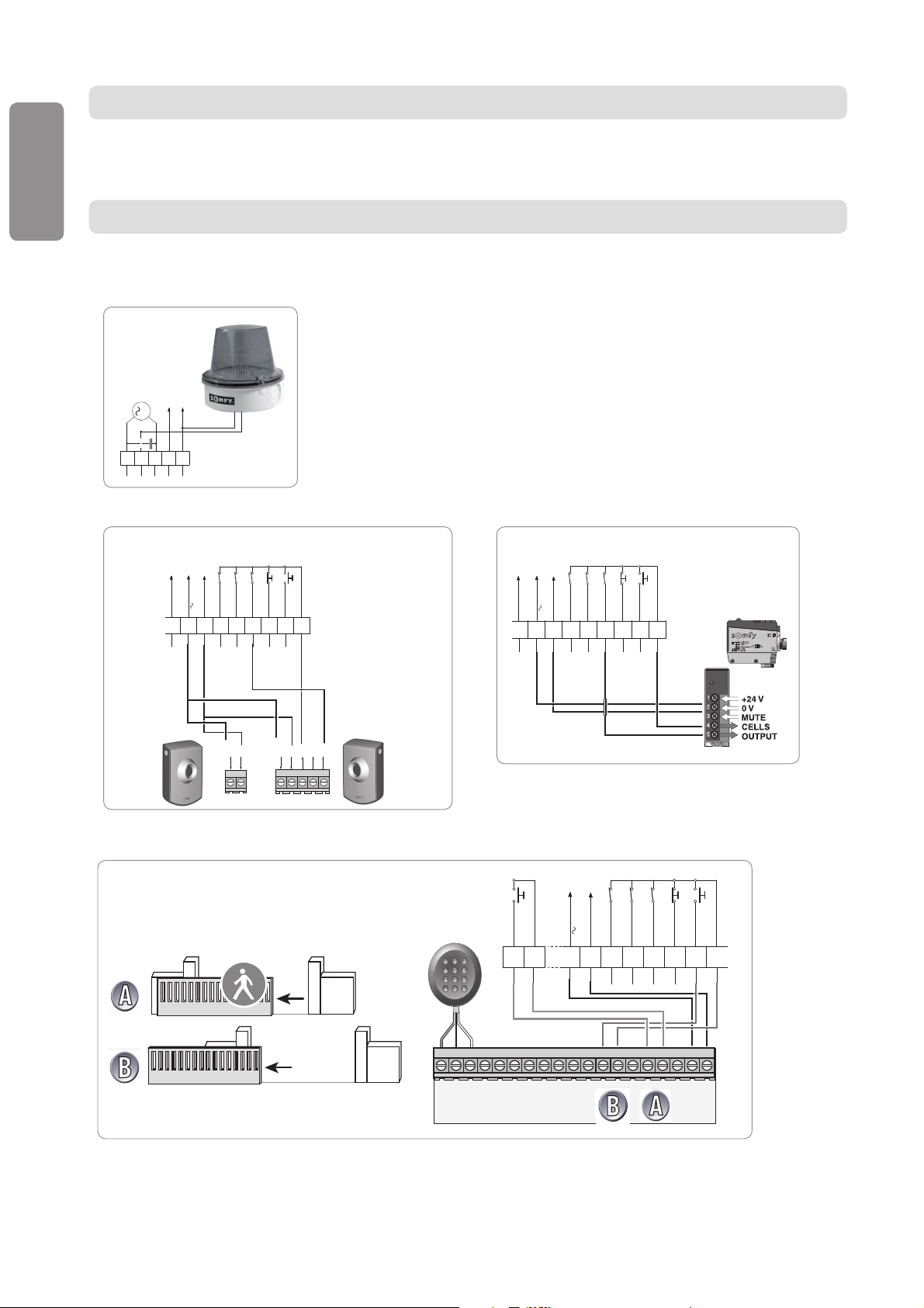
CONNECTING ADDITIONAL DEVICES
230 V integrated fl ashing amber light
(ref. 9 011 084)
Photoelectric cells Refl ex photoelectric cells
On the cell, set the DIP switch1 and the DIP switch2 to ON.
Wired keypad
8 Copyright © 2008 Somfy SAS. All rights reserved.
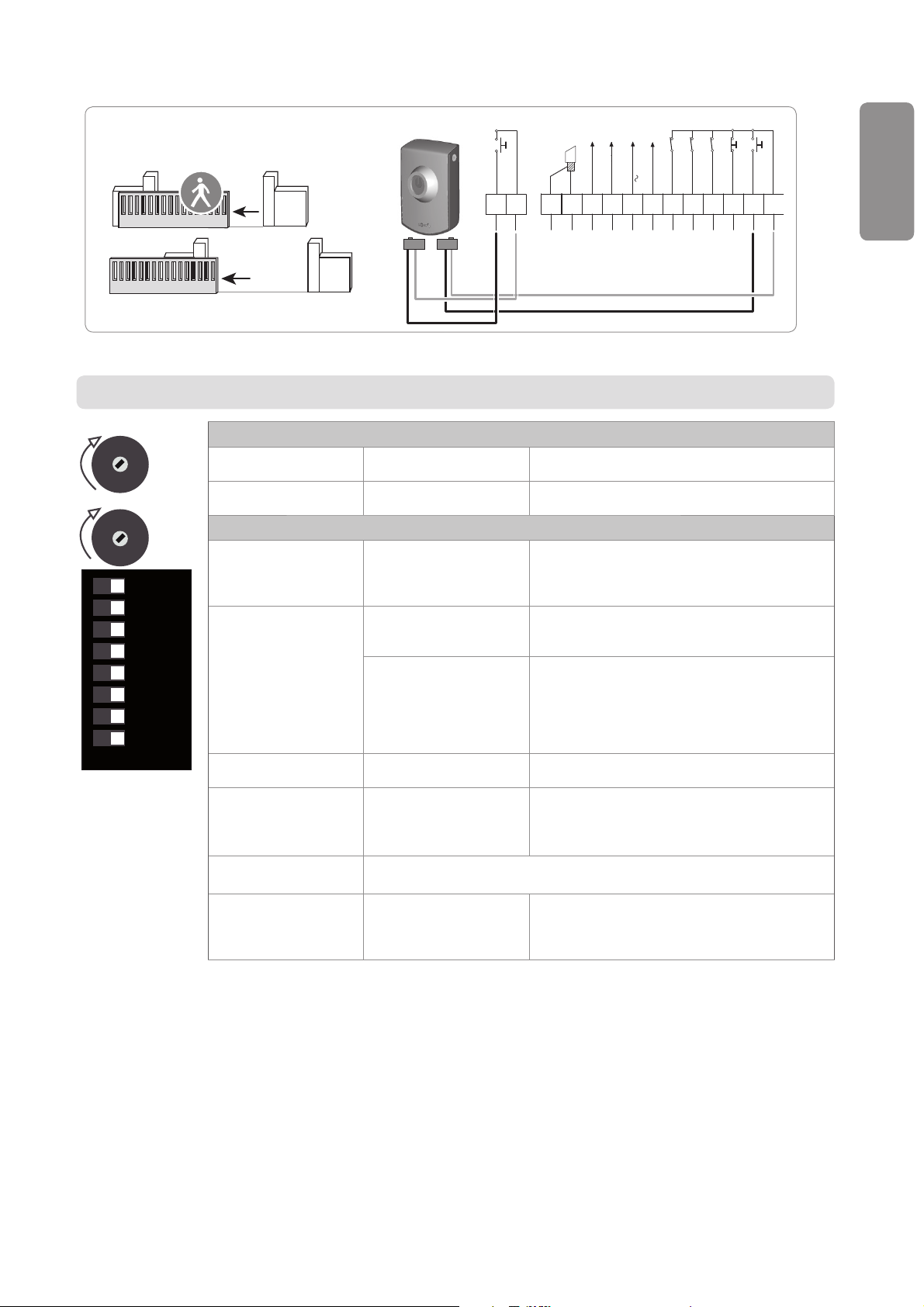
Wired keyswitch
7 s
A
A
B
B
24V
IIß RC
0V
19
20
STOPNCPHOT
NC
START
COM
NO
18
7
NC
SWO
SWC
NC
PED
8
9
11
12
141513
10
16
17
PARAMETER SETTING
Elixo 500 230 V
EN
ON
+
TCA
+
TW
-
DIP 8
DIP 7
DIP 6
DIP 5
DIP 4
DIP 3
DIP 2
DIP 1
OFF
Potentiometers: to modify the automatic closing time and the motor run time.
TCA:
Automatic closure time
TW:
Motor run time
Between 0 and 90
seconds
Between 0 and 120
seconds
Setting the time delay for automatic closing
(if DIP1 is ON).
The motor run time should be slightly longer than
the actual closing time of the gate.
DIP switch: to select the operating mode for the motor and its additional devices.
DIP 1:
Automatic closure
ON: Activates automatic
closure
The gate closes automatically after the
programmed time delay (TCA).
OFF: Deactivates
automatic closure
DIP 2:
Operation of the
photoelectric cells
ON: In closing mode only. In closing mode, the gate stops then reverses its
movement.
In opening mode, cells are inactive.
OFF: In opening and
closing mode.
In closing mode, the gate stops and reverses
its movement once the cells are no longer
obstructed.
In opening mode, the gate stops then
continues its movement once the cells are no
longer obstructed.
DIP 3:
Blocking impulses
DIP 4:
3 Step/4 Step
DIP 5
DIP 6
DIP 7
Pedestrian opening
ON: In opening mode only
Impulses during opening have no effect.
OFF: None
ON: Activates the 3 step
logic.
OFF: Activates the 4
step logic.
3 STEP = operation in semi-automatic mode
(see “User's manual” pg. 2).
4 STEP = operation in sequential mode
(see “User's manual” pg. 2).
DIP 5 and 6 are not used and have no effect on the operation of the motor
and its additional devices.
ON: Activates the
pedestrian opening.
OFF: Deactivates the
pedestrian opening.
Pressing the remote control briefl y partially opens
the gate and pressing and holding the remote
control fully opens the gate.
Fixed opening time: 7 seconds.
Copyright © 2008 Somfy SAS. All rights reserved. 9

Elixo 500 230 V
CLEARING ALL REMOTE CONTROLS
Press the PROG button on the motorisation control unit for more than 7 seconds. The indicator light fl ashes to indicate that all
remote controls have been cleared.
EN
DIAGNOSTICS
The auto-diagnostic LEDS, located on the control unit terminal, control the
operation of the motor and its additional devices.
DL2 START - lights up on the START command
DL3 STOP - goes out on the STOP command
DL4 PHOT - goes out if the photoelectric cells are not aligned or if they are
obstructed
DL5 SWO - goes out on the opening end limit command
DL6 SWC - goes out on the closing end limit command
TECHNICAL SPECIFICATIONS
MOTOR
Power supply 230 V 50Hz
Motor power supply 230 V AC
Motor revolutions 1400 rpm
Power consumption 290 W
Maximum consumed current 1.5 A (230 V) - 3 A (110 V)
Capacitor 10 μF (230 V) - 40 μF (110 V)
Thermal protection 110°C
Insulation category F
Reduction ratio 1/30
Revolutions at output 48 rpm
Pinion 4 mm module (14 teeth)
Gate speed 8.5 m/min
Maximum weight of the gate 500 kg
Maximum torque 20 Nm
Lubrication Permanent grease
Manual manoeuvres Mechanical release with handle
Number of cycles/day 100
Obstacle detection Friction clutch
Control unit Integrated
Operating temperature -20 °C to +60 °C
Index protection rating IP24
Weight 15 kg
Dimensions see “General motor size” pg. 3
ELECTRONICS
Accessories power supply 24 V (0.2 A maximum absorbed)
Automatic closure time between 0 and 90 seconds
Operating time between 0 and 120 seconds
Pedestrian opening time 7 seconds (fi xed)
Reversal pause 1 second approximately
Flashing orange light connection 230 V maximum 15 W
Fuses 250 V T 0.62 A and T 1 A
Built in radio receiver RTS
Number of storable remote controls 36
RTS remote control frequency 433.42 Mhz
Aerial resistance 50 Ohm (RG58)
10 Copyright © 2008 Somfy SAS. All rights reserved.

Elixo 500 230 V
ÍNDICE
CUESTIONES GENERALES 2
SEGURIDAD 2
Cuestiones generales 2
Normas de seguridad 2
DESCRIPCIÓN DEL PRODUCTO 3
Composición del kit 3
Descripción de la motorización 3
Dimensiones generales del motor 3
Ámbito de aplicación 4
Vista general de una instalación tipo 4
INSTALACIÓN 4
Ensamblaje del mango de desembrague 4
Desembrague de la motorización 4
Instalación de la motorización 5
Cableado 6
PUESTA EN SERVICIO RÁPIDA 7
Memorización de los telemandos 7
Ajuste del par del motor 7
ES
FUNCIONAMIENTO DE LA MOTORIZACIÓN 8
CONEXIÓN DE LOS PERIFÉRICOS 8
Luz naranja intermitente 230 V 8
Células fotoeléctricas 8
Célula réfl ex 8
Teclado de código por cable 8
Contacto de llave 9
PROGRAMACIÓN 9
BORRADO DE TELEMANDOS 10
DIAGNÓSTICO 10
CARACTERÍSTICAS TÉCNICAS 10
Copyright © 2008 Somfy SAS. All rights reserved. 1

Elixo 500 230 V
CUESTIONES GENERALES
Este producto, instalado conforme a las presentes instrucciones, permite una puesta en servicio conforme a las normas EN
12453 y EN 13241-1.
Por la presente, Somfy declara que este producto cumple con los requisitos básicos y demás disposiciones pertinentes recogidas en la
directiva 1999/5/CE. Puede consultar la declaración de conformidad válida para la UE, CH y NO en www.somfy.com/ce (Elixo 500 230 V).
SEGURIDAD
Cuestiones generales
ES
Lea siempre estas instrucciones de instalación y las normas de seguridad adjuntas antes de comenzar la instalación de este
producto Somfy.
La instalación de este producto Somfy deberá correr a cargo de un profesional de la motorización y la automatización de la
vivienda, a quien va dirigida esta guía.
El uso de cualquier accesorio de seguridad no validado por Somfy se realizará bajo la única responsabilidad del instalador.
Esta guía describe la instalación, puesta en marcha y funcionamiento del producto.
Por otro lado, el instalador deberá adecuarse a las normas y a la legislación vigente en el país de instalación y deberá informar
a sus clientes de las condiciones de uso y de mantenimiento del producto.
Todo uso diferente del ámbito de aplicación defi nido por Somfy se considera inapropiado. Esto conllevará, al igual que cualquier
otra inobservancia de las instrucciones que fi guran en este manual, la exclusión de responsabilidad y garantía por parte de Somfy.
Normas de seguridad
Antes de proceder a la instalación, asegúrese de que la estructura del portal es conforme a las prescripciones de las normas
vigentes, y en particular:
El raíl de deslizamiento del portal deberá ser lineal, horizontal y las ruedas deberán ser aptas para soportar el peso del portal.•
El portal deberá poder desplazarse con facilidad de forma manual a lo largo de su recorrido, y no deberá constatarse •
ningún bandazo lateral excesivo.
El guiado superior deberá permitir el juego exacto con el portal para asegurar un movimiento regular y silencioso.•
Los topes de parada en el suelo deberán instalarse tanto en la apertura como en el cierre.•
La posición establecida para la fi jación de la motorización deberá permitir efectuar el desembrague manual de la •
motorización de un modo fácil y seguro.
Si estos elementos comprobados no respondieran a las condiciones expuestas anteriormente, se deberán reparar o, cuando
fuera necesario, se deberán sustituir
La elección de los accesorios de seguridad de la instalación deberá ser conforme a las normas aplicables y reglamentaciones
vigentes en el país de instalación.
Asegúrese de que no existen zonas peligrosas (aplastamiento, cizallamiento, atasco) entre el portal y las partes fi jas
circundantes debidas al movimiento de apertura del portal.
Sobre un portal con barrotes, cuando los barrotes tengan un espacio superior a 40 mm entre ellos, instale el dispositivo de
seguridad adecuado para evitar el cizallamiento.
Conserve una zona despejada de 500 mm en la parte posterior del portal cuando esté completamente abierto.
Mantenga el portal a la vista durante el movimiento.
Mantenga los dispositivos de control fi jos y los dispositivos a distancia fuera del alcance de los niños.
Todo interruptor sin bloqueo deberá instalarse a la vista directa del portal, aunque alejado de las partes móviles. Deberá
instalarse a una altura mínima de 1,5 m y no deberá ser accesible al público.
Durante la instalación de la motorización:
Retírese todas las joyas (pulseras, cadenas y otras).•
Para las operaciones de taladrado y soldadura, utilice gafas especiales y las protecciones adecuadas.•
Utilice herramientas adecuadas.•
No se conecte a la red eléctrica o a una batería auxiliar antes de haber fi nalizado la instalación.•
Manipule con precaución el sistema de motorización para evitar cualquier riesgo de lesiones.•
Para su funcionamiento, la motorización deberá recibir una alimentación de 230 V 50 Hz. La línea eléctrica deberá:
estar reservada exclusivamente a la motorización,•
contar con una sección mínima de •
estar equipada con un interruptor omnipolar homologado con apertura de los contactos de al menos 3,5 mm, dotado con •
una protección (fusible o disyuntor de calibre 16 A) y un dispositivo diferencial (30 mA),
instalarse según las normas de seguridad eléctrica vigentes.•
1,5 mm²,
2 Copyright © 2008 Somfy SAS. All rights reserved.
 Loading...