

SOMFY Dexxo Pro Installation Manual

1
GB
GENERAL PRESENTATION 2
SAFETY INSTRUCTIONS 2
Caution 2
Safety instructions 2
PRODUCT DESCRIPTION 2
Product components 2
Types of door 2
POINTS TO CHECK PRIOR TO INSTALLATION 3
Preliminary checks 3
Safety instructions 3
INSTALLATION 3
Installation height 3
Detailed description of installation steps 3
PROGRAMMING 5
Programming button description 5
Learning 5
Memorising remote controls 5
OPERATING TEST 5
Using the remote controls 5
Obstacle detection function 5
Built in lighting operation 6
CONNECTING PERIPHERALS 6
Description of the various peripherals 6
Electrical connections for the various peripherals 6
SETUP 7
Setup general diagram 7
Definition of the different settings 7
SPECIAL OPERATION 8
CLEARING REMOTE CONTROLS AND ALL SETTINGS 8
Clearing remote controls 8
Resetting all settings 8
TROUBLESHOOTING 8
Operating codes displayed 8
Programming codes displayed 9
Error and failure codes displayed 9
Accessing stored data 9
TECHNICAL SPECIFICATIONS 10
CONTENTS
5048551A-GB 26/04/07 14:36 Page 1
www.garagedoorsonline.co.uk
01926 463888
www.garagedoorsonline.co.uk
www.garagedoorsonline.co.uk
01926 463888
www.garagedoorsonline.co.uk
2
GB
This product complies with the “safety, specific rules for powering vertically opening garage doors in residential use” requirements (standard EN
60335-2.95). When installed in line with these instructions and in compliance with the “Installation Checklist”, the product will be compliantwith
standards EN 13241-1 and EN 12453.
The instructions referred to in the installation manual and instructions for use of this product are designed to prevent damage to property and
personal injury along with compliance with the above standards. Failure to comply with these instructions absolves Somfy from any liability resulting
from damage that may be caused. Dexxo Pro is a product that must be installed inside the garage with an integrated back-up control system.
Somfy hereby declares thatthe device is compliant with the essential demands and other relevant requirements of directive 1999/5/CE.
A declaration of compliance is available from the web site at
www.somfy.com/CE (Dexxo Pro).
This product is suitable for use in the European Union and in Switzerland.
GENERAL PRESENTATION
Caution
These are important safety instructions. Always follow the instructions, incorrect installation may lead to serious injury.
Safety instructions
Before installing the motor drive unit, remove all unessential lines or chains and switch off all equipment that is not essential for motorised door
operation.
Before installing the motor drive unit, make sure that the door is in good mechanical condition, that it is properly balanced and that it opens and
closes correctly.
Locate all control systems at least1.5 metres above floor level, making sure that they are visible from the entrance to the garage but safe from moving
parts.
Position the manual release cord no more than 1.8 metres above floor level.
Whe
re a removable release mechanism is used, we recommend storing it close to the door.
Fix the label describing the manual release procedure close to the release mechanism.
Fix the warning labels describing the hazards of doormotion close to any fixed control mechanisms installed and make sure that the labels are clearly
visible to the user.
After installation, make sure that the mechanism is correctly adjusted and that the motor drive unit reverses its motion when the door encounters
an obstacle that is at least 50 mm from floor level.
After installation, make sure that no part of the door overhangs an area accessible to the public.
After installation, make sure that the motor drive unit inhibits or stops the door opening motion when the door is loaded down with a 20 kg weight
attached to a central position of the door’s bottom edge.
SAFETY INSTRUCTIONS
PRODUCT DESCRIPTION
Product components
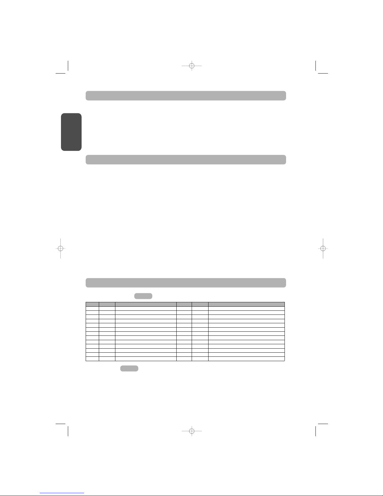
Fig. 1
Key Number Description Key Number Description
1
1 Motor head 14 4 Hex. head M8x12 bolt & washer
2 1 Motor cover 15 6 HU8 nut
3 1 Built-in light cover 16 2Shaft
4 1 Lintel bracket 17 2 Circlips
5 1 Door bracket 18 4
Self-tapping φ3x10 screw
6 2 Ceiling bracket 19 4
Self-shaping φ4x8 screw
7 2 Motor head bracket 20 2
Special screw for plastic
φ
3.5x12
8
1
Manual release cord
21a 1 Single part rail
9
1
Link arm 21b 1 Two part rail
10
2
Travel stop 21b1 1 Sleeve
11
4
Chain retainer pad 21b2 8
Self-shaping φ4x8 screw
12
1
Power cable 22 2 Keytis remote control
13 2 Hex. head M8x16 bolt 23 1 230 V 40 W E14 socket light bulb
Types of doors
A: Projecting up and over door.
B: Sectional door. If the door surface exceeds 10 sq. metres or if the upper profile is a specific one, use the sectional door kit, ref.: 2400650.
C: Swinging door. Use the swinging door kit, ref.: 2400459.
D: Semi-projecting up and over door (canopy door). Use the semi-projecting up and over door kit, ref.: 2400458.
Fig. 2
5048551A-GB 26/04/07 14:36 Page 2
www.garagedoorsonline.co.uk
01926 463888
www.garagedoorsonline.co.uk
www.garagedoorsonline.co.uk
01926 463888
www.garagedoorsonline.co.uk

3
GB
POINTS TO CHECK PRIOR TO INSTALLATION
Preliminary checks
Check the garage door can be operated manually and runs smoothly. Ensure the door is in good mechanical condition (pulleys, mounts…) and is
correctly balanced (spring tension).
Remember that any work performed on door springs may be dangerous.
The structure of your garage (walls, lintel, inside surfaces, cross members, door rails…) are used to mountthe Dexxo Pro system. Reinforce them where
necessary.
Never splash water onto the system. Never install Dexxo Pro in a location where water may cause damage.
The bottom edge of the door should be fitted with a rubber strip to avoid hard contact and enhance the contact surface.
If the garage door is the only entry point into the garage, fit an external release (external release keylock (ref. 9012961) or an external release
(ref. 9012962) and include a back-up battery (ref. 9001001).
If the garage door includes a separate pedestrian door, the door must be fitted with an interlock to prevent garage door movement when the
pedestrian door is open (pedestrian door safety kit ref. 2400657).
If the garage door opens on to a public road, install an indicator light, such as a flashing orange light (ref. 9012762).
If the garage door operates in automatic mode, install a photoelectric cell type safety system (ref. 9012763 or ref. 9013647) and a flashing orange
light type indicator.
Make sure that the door does not comprise any accessible parts.
Unlocking the door may trigger uncontrolled door movement if the door is not balanced correctly.
Safety instructions
Safety instructions must be complied with throughout the installation process:
. Take off any personal jewellery (bracelet, chain or others) during installation work.
. During drilling and welding work, always wear safety glasses and suitable protection.
. Always use suitable tools.
. Take care when handling the motor drive system.
. Never connect the mains power supply or the battery back-up system before completing the installation process.
. Never use high pressure water systems for cleaning purposes.
Door dimensions (Fig. 3)
For maximum door heights, the motor travel can be optimised:
. By installing the motor head at a 90° angle (
AAbbbb.. 77--
).
. By fixing the lintel bracket to the ceiling, behind the lintel itself by up to 200 mm (
AAbbbb.. 55--
).
. By cutting the link arm to size.
Installation height
Measure the distance “D” between the door’s highest point and the ceiling.
If “D” is between 35 and 200 mm, mount the complete system straightonto the ceiling.
If “D” exceeds 200 mm, mount the system so that the height “H” falls between 10 and 200 mm.
Detailed description of installation steps
Mounting the lintel bracket and the door bracket (Fig. 5).
When installing the system directly onto the ceiling (flush with the ceiling), the lintel bracket can be mounted on the ceiling, if necessary recessed
from the lintel by up to 200 mm max.
(Fig. 5--).
Assembling the two part rail (Fig. 6)
[1] [2] [3]. Unfold the two parts of the rail.
[4]. Assemble the two parts of the rail using the sleeve.
[5]. Mount
the complete assembly using the eight mounting screws.
When installing the system directly onto the ceiling, do not use the sleeve mounting screws.
Figs. 5 to 16
Fig. 4
INSTALLATION
5048551A-GB 26/04/07 14:36 Page 3
www.garagedoorsonline.co.uk
01926 463888
www.garagedoorsonline.co.uk
www.garagedoorsonline.co.uk
01926 463888
www.garagedoorsonline.co.uk

4
GB
Fitting the rail onto the motor head (Fig. 7)
Fitting the complete assembly onto the garage ceiling (Figs. 8 to 10)
Fitting to the lintel bracket (Fig. 8)
Ceiling mounting
. Flush with the ceiling: mount the system directly onto the ceiling using the rail (Fig. 9).
It is possible to add mounting points at the motor head level (
Fig. 9--).
. Hung from the ceiling
(Fig. 10)
Intermediate mounting points can be added to the rail, especially in the case of a two part rail or a rail that measures 3.5M in length (Fig. 10--).
Fitting the arm onto the door and the trolley (Fig. 11)
[1].
Release the trolley using the manual release cord
[2]. Bring the trolley up to the door
[3]. Attach the arm to the door bracket and the trolley
Fastening and adjusting the travel stops (Figs. 12 and 13)
Close travel stop (Fig. 12)
[1].
Release the trolley from the runner using the manual release mechanism and bring the door to the closed position.
Fully close the door.
[2]. Position the close travel stop against the trolley and attach it to the rail.
Open travel stop
(Fig. 13)
[1].
Release the trolley from the runner using the manual release mechanism and bring the door to the open position.
Do not open the door fully, but position it so that it does not reach the travel stops.
[2]. Position the open travel stop against the trolley and attach it to the rail.
Note: The stop positions can be set by positioning the door open or closed using the forced operation mode
(Fig. 39).
Fitting the chain retainer pads (Fig. 14)
For chain rails only.
Position the chain retainer pad into the first hole in the rail after each travel stop.
Be sure to press the pad all the way down so that the positioning pin sticks out from the rail.
Make sure that the manual release cord is located at a maximum height of 1.80 metres off the ground. If necessary, extend
the cord.
Checking the chain or belt tension (Fig. 15)
Dexxo Pro is supplied with the tension preset and checked. If necessary, adjust the tension.
The rubber or tension spring must never be full compressed during operation.
Connecting the mains power supply (Fig. 16)
[1].
Remove the motor cover and the protective sheet.
[2]. Fit the light bulb.
[3]. Connect to the mains supply.
Plug the power cable into a suitable power outlet that complies with electric power requirements.
The electric supply must be suitably protected (a fuse or circuit breaker with a 5 A rating) and a residual current device
(30 mA).
An omnipolar disconnection mechanism must be provided for the power supply:
. by using a power cord with a mains splug that can be disconnected, or
. by fitting a switch that ensures a contact separation distance of at least 3 mm for each pole (refer to standard EN60335-1)
5048551A-GB 26/04/07 14:36 Page 4
www.garagedoorsonline.co.uk
01926 463888
www.garagedoorsonline.co.uk
www.garagedoorsonline.co.uk
01926 463888
www.garagedoorsonline.co.uk
5
GB
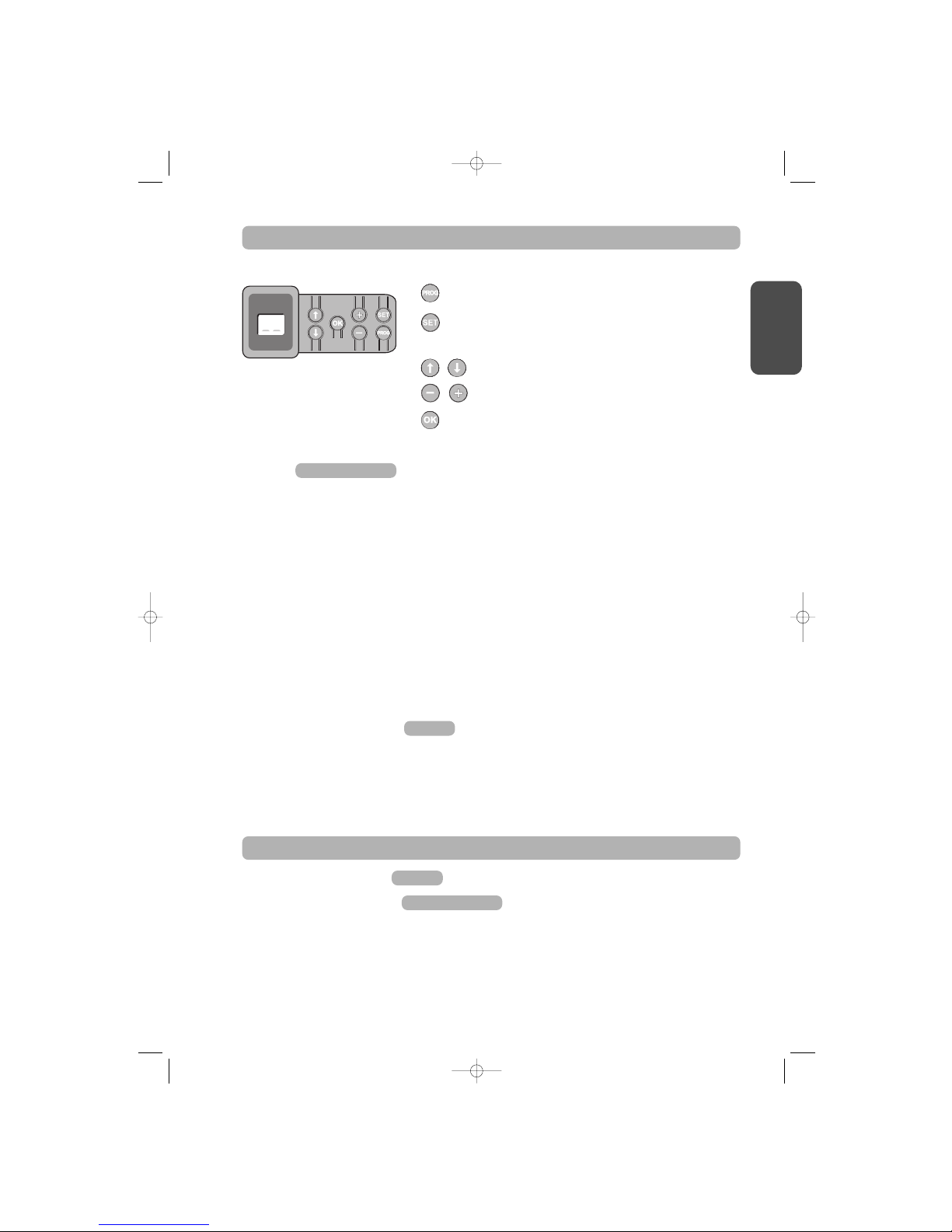
Programming button description
. Press for 2 s: memorise remote controls
. Press for 7 s: delete remote controls
. Press for 0.5 s: call up and exit the setup menu
. Press for 2 s: start learning
. Press for 7 s: clear learning and settings
. Stop learning
. Selecting a setting
. Modifying a setting value
. Using the forced mode
. Start the learning cycle
. Confirm setting selection
. Confirm setting value
Learning
Setting the type of door (Fig. 17).
The motor is already setup to workwith up and over or sectional doors (Display S1). When the motor drive unit is used with a swinging door, change
the setup by pressing the “
+” or “-” buttons until the S0 value is displayed.
Learning (Fig. 18).
[1].
Press the “SET” button until the light comes on (2 s).
The display shows “
S2”
[2]. Press the “-” or “+” buttons until the transmission system runner moves to link up with the trolley:
. Pressing and holding the “
-” button moves the runner in the close direction.
. Pressing and holding the “+” button moves the runner in the open direction.
[3]. Press the “OK” button to start the learning cycle.
The door moves to the closed position, then performs a complete open and close cycle.
. If learning was correct, the display will show “
C1”.
. If the learning cycle was not completed correctly, the display will show “S0” or “S1”.
The learning cycle can be run at any time when the trolley is engaged and the display shows “S2”.
During the learning cycle:
. If the door is moving, pressing any button will stop the movement and interrupt the learning mode.
. If the door is stopped, pressing “
SET” once will exit the learning mode.
You can call up the learning mode at any time, even when the learning cycle has already been executed and the display shows “
C1”.
Memorising remote controls
Up to 32 control channels can be stored.
Running this procedure for a previously stored channel will clear it.
At this stage in the installation process, the Dexxo Pro motor drive unit is ready to run.
Fig.
19
Figs. 17 and 18
OPERATING TEST
Using the remote controls
Obstacle detection function
The detection of an obstacle during door opening will stop the door (Fig. 21).
The detection of an obstacle during door closure will reopen the door
(Fig. 22).
Make sure that obstacle detection works when the door encounters an obstacle 50 mm from the ground.
Figs. 21 and 22
Fig.
20
PROGRAMMING
5048551A-GB 26/04/07 14:36 Page 5
www.garagedoorsonline.co.uk
01926 463888
www.garagedoorsonline.co.uk
www.garagedoorsonline.co.uk
01926 463888
www.garagedoorsonline.co.uk
6
GB
Electrical connections for the various peripherals
Cut the electric power supply to the motor before performing any work on peripherals. If the display remains off after working on the system, check
the wiring (for possible short circuits or polarity reversals).
General electrical diagram (Fig. 23)
Photoelectric cells (Fig. 24)
Two types of connections can be made:
A: Standard (without self test): program the setting “P2” = 2.
B: With self test: program the setting “P2” = 1.
This means that an automatic test is conducted to check photoelectric cell operation every time the door operates.
If the test fails, no door movement is possible.
Reflex photoelectric cell (Fig. 25)
With self test: program the setting “P2” = 1.
This means that an automatic test is conducted to check photoelectric cell operation every time the door moves.
If the test fails, no door movement is possible.
Sensor bar (Fig. 26)
With self test: program the setting “P2” = 1.
This is used to perform an automatic test of sensor bar operation every time the door moves.
If the test result is negative, no door movement is possible.
Make sure you have correctly configured parameter “P2” taking into account the photoelectric cells or the sensor bar.
Orange light (Fig. 27)
Program the setting “P1” depending on the required operating mode:
. Without warning before door movement: “
P1” = 0.
. With a 2 s warning before door movement: “
P1” = 1.
Code keypad (Fig. 28)
Pedestrian door safety kit (Fig. 29)
When the pedestrian door contact is fitted, it must be connected in place of the jumper normally fitted between terminals 5 and 6 in the terminal
block.
If the pedestrian door contact is removed, the jumper between terminals 5 and 6 in the terminal block must be refitted.
Battery (Fig. 30)
Antenna (Fig. 31)
Remote lighting (Fig. 32)
Class 2 (double insulation) light units that are connected do not require an earth connection.
If a Class 1 (single insulation) light unit is used, always connect it to earth.
Figs. 23 to 32
CONNECTING PERIPHERALS
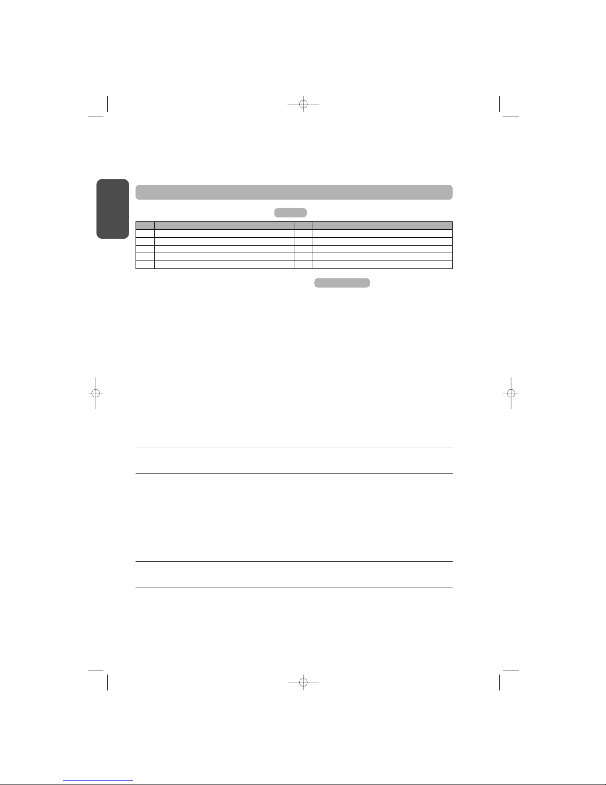
Key Description Key Description
1 Orange light 6 Battery
2 Remote lighting 7 Pedestrian door safety kit
3 Code keypad 8 Photoelectric cells
4 Keyswitch 9 Reflex type cells
5 Antenna 10 Sensor bar
Description of the various peripherals
Fig. 23
Built in lighting operation
The light will come on every time the motor drive unit is operated. It will go out automatically after one minute once the door stops. This time delay
is adjustable (refer to the Setup chapter). Repetitive use which causes the light to stay on continually may result in an automatic cut-off condition
triggered by the thermal cut out protection mechanism.
5048551A-GB 26/04/07 14:36 Page 6
www.garagedoorsonline.co.uk
01926 463888
www.garagedoorsonline.co.uk
www.garagedoorsonline.co.uk
01926 463888
www.garagedoorsonline.co.uk
 Loading...