

Page 1
Tire Pressure Sensor System Tool Kit
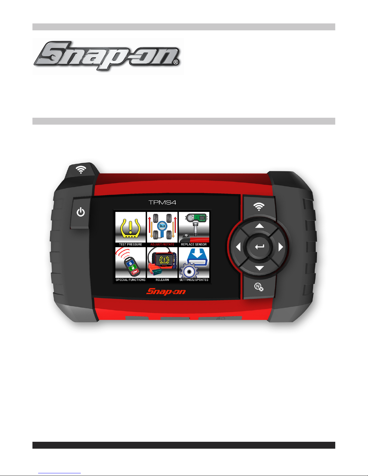
TPMS4
TPMS diagnostic tool that tests tire pressure monitoring sensors, captures sensor
data and relearns tire pressure monitoring systems. Also programs aftermarket
sensors and prints sensor information. Perfect complement to a shop or technician
that owns a Snap-on® diagnostic platform.
Page 2

Contents
TPMS4 User Manual Cover. . . . . . . . . . . . . . . . . . . . . . . . . . . . . . . . . . . . . . . . . . . . . . . . . . . . . . . . . . . . . . . 1
Contents. . . . . . . . . . . . . . . . . . . . . . . . . . . . . . . . . . . . . . . . . . . . . . . . . . . . . . . . . . . . . . . . . . . . . . . . . . . . . . 2
Safety Information. . . . . . . . . . . . . . . . . . . . . . . . . . . . . . . . . . . . . . . . . . . . . . . . . . . . . . . . . . . . . . . . . . . . . . 3
Safety Precautions . . . . . . . . . . . . . . . . . . . . . . . . . . . . . . . . . . . . . . . . . . . . . . . . . . . . . . . . . . . . . . . . . . . . . 4
Federal Communication Commission Interference Statement . . . . . . . . . . . . . . . . . . . . . . . . . . . . . . . . . . 5
Chapter 1: What’s Included Features and Layout . . . . . . . . . . . . . . . . . . . . . . . . . . . . . . . . . . . . . . . . . . . . 6
Chapter 2: Basic Tool Operation and Navigation. . . . . . . . . . . . . . . . . . . . . . . . . . . . . . . . . . . . . . . . . . . . . 7
A)
Test Pressure . . . . . . . . . . . . . . . . . . . . . . . . . . . . . . . . . . . . . . . . . . . . . . . . . . . . . . . . . . . . . . . . . . . . 8
B)
Adjust / Rotate . . . . . . . . . . . . . . . . . . . . . . . . . . . . . . . . . . . . . . . . . . . . . . . . . . . . . . . . . . . . . . . . . . . . 9
C)
Replace Sensor. . . . . . . . . . . . . . . . . . . . . . . . . . . . . . . . . . . . . . . . . . . . . . . . . . . . . . . . . . . . . . . . . . 10
D)
Special Functions . . . . . . . . . . . . . . . . . . . . . . . . . . . . . . . . . . . . . . . . . . . . . . . . . . . . . . . . . . . . . . . . 11
E)
Relearn . . . . . . . . . . . . . . . . . . . . . . . . . . . . . . . . . . . . . . . . . . . . . . . . . . . . . . . . . . . . . . . . . . . . . . . . 12
F)
Settings / Updates . . . . . . . . . . . . . . . . . . . . . . . . . . . . . . . . . . . . . . . . . . . . . . . . . . . . . . . . . . . . . . . . 13
G)
Settings / (Update) . . . . . . . . . . . . . . . . . . . . . . . . . . . . . . . . . . . . . . . . . . . . . . . . . . . . . . . . . . . . . . . 14
Chapter 3: PC Print Instuctions . . . . . . . . . . . . . . . . . . . . . . . . . . . . . . . . . . . . . . . . . . . . . . . . . . . . . . . . . . 15
TPMS4 Warranty / Service and Repair. . . . . . . . . . . . . . . . . . . . . . . . . . . . . . . . . . . . . . . . . . . . . . . . . . . . . 16
Page 3
Safety Signal Words
All safety messages contain a safety signal word that indicates the level of the hazard. An
icon, when present, gives a graphical description of the hazard. Safety Signal words are:
Indicates an imminently hazardous situation which, if not avoided, will result in death or
serious injury to the operator or to bystanders.
Indicates a potentially hazardous situation which, if not avoided, could result in death or
serious injury to the operator or to bystanders.
Indicates a potentially hazardous situation which, if not avoided, may result in moderate or
minor injury to the operator or to bystanders.
Safety Message Conventions
Safety messages are provided to help prevent personal injury and equipment damage. Safety
messages communicate the hazard, hazard avoidance and possible consequences using
three different type styles:
• Normal type states the hazard.
• Bold type states how to avoid the hazard.
• Italic type states the possible consequences of not avoiding the hazard.
An icon, when present, gives a graphical description of the potential hazard.
Safety Message Example
Risk of unexpected vehicle movement.
• Block drive wheels before performing a test with engine running.
A moving vehicle can cause injury.
SAVE THESE INSTRUCTIONS
3
Page 4
SAFETY PRECAUTIONS
TPMS4 QTY: 1
Caution! Lithium-Ion Battery
For Emergencies only. Call CHEMTREC
1-800-424-9300 US and Canada
+1-703-741-5970 International
3.8V 20.0 Amps 11.59 Wh
FCC ID: 2ANR7-TPMS4
WARNING
• Use of diagnostic equipment can cause electrical shock, fire and explosion.
Use caution and proper procedures when connecting
Diagnostic equipment
must be located 18" or more above floor level. Avoid
and disconnecting leads.
sparks and other sources of ignition.
Electrical shock, flames and explosion can cause serious injury.
• Improper use can cause hazardous conditions.
Read and follow all safety precautions accompanying the product. Wear safety
goggles.
Unexpected electrical, thermal or mechanical occurrences can cause injury.
• Electromagnetic and electronically generated waves may interfere with
pacemakers.
Individuals with pacemakers should never use this product.
Using this product with a pacemaker can result in serious injury or death.
• Internal battery presents a risk of fire, explosion and electric shock.
Charge battery pack only with charger provided.
Do not store at temperatures above 120°F (49°C).
Do not discard used batteries; return them to a Snap-on repair center for
recycling. Follow all safety messages in user manual.
Fire or explosion or electric shock can cause injury.
This device complies with Part 15 of the FCC Rules. Operation is subject to the following two conditions:
(1) This device may not cause harmful interference, and
(2) This device must accept any interference received, including interference that may cause undesired operation.
4
Page 5

Federal Communication Commission Interference Statement
This equipment has been tested and found to comply with the limits for a Class B
digital device, pursuant to Part 15 of the FCC Rules. These limits are designed to provide
reasonable protection against harmful interference in a residential installation. This
equipment generates, uses and can radiate radio frequency energy and, if not installed and
used in accordance with the instructions, may cause harmful interference to radio
communications. However, there is no guarantee that interference will not occur in a
particular installation. If this equipment does cause harmful interference to radio or
television reception, which can be determined by turning the equipment off and on, the user
is encouraged to try to correct the interference by one of the following measures:
Reorient or relocate the receiving antenna.-
-
-
Increase the separation between the equipment and receiver.
Connect the equipment into an outlet on a circuit different from that to which
------------------the receiver is connected.
- Consult the dealer or an experienced radio/TV technician for help.
FCC Caution: Any changes or modifications not expressly approved by the party
responsible for compliance could void the user's authority to operate this equipment.
This device complies with Part 15 of the FCC Rules. Operation is subject to the
following two conditions: (1) This device may not cause harmful interference, and (2) this
device must accept any interference received, including interference that may cause
undesired operation.
5
Page 6

Directional
Buttons
Test
Button
Antenna
Power
(On/ Off)
Button
Enter
No / Cancel
Button
N
USB
USB Jack SD Card Slot
RJ45 Jack
SD
RJ45
Chapter 1: Introduction
Battery
Replacement
Screws*
TPMS diagnostic tool that tests tire pressure monitoring sensors, captures sensor data and
relearns tire pressure monitoring systems. Also programs aftermarket sensors and prints
sensor information
.
Kit Contents
TPMS4
Diagnostic Tool
TPMS3-4
USB Cable
TPMS4-7
AC/DC Power Adapter
TPMS4-9
Soft Carry Case
TPMS4-10
TPMSconnect USB
Jump Drive
Battery Replacement
Bottom View
Nylon Soft Case
* Torque to 0.26 – 0.43 in-Lb
Included Power Adaptors
6
Page 7

Chapter 2: Basic Tool Operation and Navigation
When testing sensor position TPMS4 antenna on sidewall
near valve. Press TEST to trigger sensor.
On certain applications such as Asian
vehicles, a Snap-on diagnostic scan
tool is required to place the vehicle into
relearn mode. For these applications,
the TPMS4 triggers the TPM sensors in
order to register the sensor IDs to the
on-board vehicle computer.
7
Page 8

MAKE / MODEL / YEAR
1
2
3
4
5
6
SILVERADO
/
TEST NEXT
2015
2016
2017
2004
2005 - 2006
2007 - CLAMP-IN
2007 - SNAP-IN
2008 - 2009 - SNAP-IN
CHEVROLET
/
TEST NEXT
EQUINOX
EXPRESS SERIES
HHR
IMPALA
MALIBU
MONTE CARLO
ORLANDO
SILVERADO
VEHICLE SELECTION
/
TEST NEXT
CADILLAC
CHEVROLET
CHRYSLER
CODA
DODGE
FERRARI
FIAT
FISKER
SELECT TIRE PRESS
OR USE ARROWS ON KEYPAD
TO TEST PRESS
SILVERADO
TROUBLESHOOTER STOP
SILVERADO
TROUBLESHOOTER END
SILVERADO
TROUBLESHOOTER END
ODBAF869
36.0 PSI
315MHz
TRIGGER PROCESSING
82º
BAT : OK
1.0 g
A
Test Pressure
Perform this function to retrieve TPM sensor information,such as Unique sensor ID, Pressure,
Frequency,Temperature, Battery status (Note: Ford banded style-sensors requires the triggering to be performed 180 degree from valve stem).The following sensor information
insures that the TPMS sensor is correct and that it is working as designed.
8
Page 9

ROTATE
ADJUST
INCREASE OR DECREASE AIR PRESSURE
2010 GMC SIERRA
EXPANDS TPMS4 TOOL TO INCLUDE INFLATION
1
2 2
3
3
Tech Support #844.349.8767
help@tpms4.com
SN : B365-06685
VERSION : JALL2-07-02
BOOTLOADER : 02.000
DATABASE : JYA1-56
RELEARN : JZA1-56
SIERRA ALL
With Keyless Entry
With DIC Button
With Odometer Reset
Tech Support #844.349.8767
help@tpms4.com
SN : B365-06685
VERSION : JALL2-07-02
BOOTLOADER : 02.000
DATABASE : JYA1-56
RELEARN : JZA1-56
SIERRA ALL
Make sure TPMS MIL light is Solid
not flashing.
Adjust tire pressure to tire placard
value.
Use TPMS4 to check all sensors.
Press NEXT to trigger all
sensors in the tires.
SIERRA ALL
With Odometer Reset
1. Inflate all tires
2. Apply parking brake
3. Turn Ignition ON
4. Push and hold the trip odometer
reset stem on instrument panel
until PRESS ✓ TO RELEARN TIRE
/
TEST NEXT
/
TEST
NEXT
SELECT TIRE PRESS
OR USE ARROWS ON KEYPAD
TO TEST PRESS
SIERRA ALL
TROUBLESHOOTER STOP
B
Adjust / Rotate
Perform the TPM system reset of relearn procedure after tire service, such as a rotate or after
pressure adjustment.Note: Cold pressure adjustment is always recommended when adjusting
pressure to recommended placard specification.
9
Page 10

PROGRAMMABLE
OE / OE STYLE
INSTALL SENSOR
SELECT SENSOR
2015 GMC ACADIA
CREATE NEW ID
READ OE SENSOR
COPY ID
CREATE SENSOR
OE RELEARN/RESET
OE RELEARN/RESET
OE RELEARN/RESET
COPY ID
1
2
4
2
3
C
1
Use black EZ-sensor
or 33500 EZ-sensor
GMC
ALLIGATOR SENS.IT
BWD STANDARD QWIK
DYNAMIC PRO SELECT
ECHLIN NAPA QWIK
HAMATO N UPRO
HUF INTELLISENS
PROGRAMMABLE
ACADIA
ID : 586AC27C
SUCCESSFUL
INSTALL IN TIRE
4
ACADIA
COPY ID
ACADIA
ID : 586AC27C
SUCCESSFUL
INSTALL IN TIRE
1
OE
BWD STANDARD OE
DILL VDO REDI
DORMAN DIRECT
ECHLIN NAPA OE
OE / OE STYLE
PROGRAMMABLE
MAX TOTAL
ORANGE UNIVERSAL
PDQ
SCHRADER EZ
STEELMAN SELECT
TYC SENSOR
/
TEST NEXT
/
NEXT
Use 33500 (rubber valve),
33700 (alluminum valve), or
33000 EZ-sensor
OE / OE STYLE
/
NEXT
/
NEXT
/
NEXT
/
TEST NEXT
/
TEST NEXT
C
Adjust / RotateReplace Sensor
Perform vehicle sensor replacement for OE or aftermarket Programmable sensor brands. Follow
on screen instructions as well as relearn the TPM system after all sensors have been replaced.
Each specific relearn procedure is provided along with sensor programming instructions.
10
Page 11

1
2
SPECIAL FUNCTIONS
KEY FOB /RF TEST
REDI SENSOR UNLOCK
315 MHz
0% 50% 100%
PRESS KEY FOB BUTTON
D
Special enhanced functions are enabled to the TPMS4 that allows the user to perform and insure
that the vehicle will achieve relearn mode and the registration of the new sensor ID's are successful. The special functions will include Key fob testing, REDI Sensor - Unlock, and future
TPMS procedures.
Special Functions
11
Page 12

MAKE / MODEL / YEAR
RELEARN PROCEDURE
AFTER RELEARN PROCEDURE IS
COMPLETED DRIVE VEHICLE. IF FLASHING
TPMS LIGHT IS ON CONNECT SCAN TOOL
TO RETREIVE TPMS CODES
1
2
3
ALTIMA
This process requires the use of
your Snap-on Scan tool.
Connect Scan tool to OBDII port
and select TPMS from Menu. Use
of TPMS4 will be required to
activate all sensors.
GMC ACADIA
1. Inflate all tires
2. Turn Ignition ON
3. Press and hold unlock and lock
button on key fob until horn
sounds
4. Use TPMS4 to activate LF Sensor
5. Single horn sounds
TROUBLESHOOTER STOP
TROUBLESHOOTER STOP
E
Relearn
Specific vehicle instructions to assist in registering the new sensor ID's after a new sensor replacement. Instructs for the use of Snap-on diagnostic equipment to scan for DTC codes, as it
may direct the user to an in-depth diagnosis. Diagnosis of all DTC's is always recommended before a successful RELEARN can be achieved.
12
Page 13

TOOL SETTINGS
G
1 2
3 4
5
REGION : AMERICA
UNITS : PSI / F
FORMAT : AUTO
BUZZER ON : YES
AUTO OFF : 5 minutes
LANGUAGE : ENGLISH
ABOUT
SETTINGS
AMERICA
EUROPE
REGION
PSI/ºF
PSI/ºC
kPa/ºC
kPa/ºF
bar/ºF
bar/ºC
UNITS
Tech Support #844.349.8767
support@tpmsconnect.com
SN : B365-06685
VERSION : JALL2-07-02
BOOTLOADER : 02.000
DATABASE : JYA1-56
RELEARN : JZA1-56
ABOUT
LOADING. . .
EUROPE
F
Setting / Updates
Customizable settings to suit the user's preference, such as world regions, SI or Metric, and language.
13
Page 14

TPMSCONNECT
CONNECT USB DRIVE TO PC
CONNECT TPMS4 TO PC
G
Setting / (UPDATE)
USB Jump Drive TPMSconnect
The USB jump drive is used to install the TPMSconnect portal and also includes TPMS4 User's
manual. Insert the USB Jump Drive into the PC or Laptop USB port and follow the on-screen instructions. This will provide the user with initial product registration and it will also bring the TPMS4
to the most current software version. After the first 12-months the purchase of TPMS4U update
will allow software updates for a 12-month time period.
14
Page 15

Chapter 3: PC Print Instructions
Print Sensor Information–
Connect to PC to print the last vehicle sensor data screen.
Printing sensor information such
as Sensor ID, Pressure, Temperature and Battery condition is a
feature of the TPMS4. This function is performed after triggering
the vehicle sensors and connecting the TPMS4 through the
WebTPM portal. In some cases,
printing sensor information
requires the most current software version to be functional.
IMPORTANT:
This feature is only available after
the user has triggered the TPM
sensors in the vehicle, and the
tool has not been turned off.
1) Trigger TPM sensors with the
TPMS4.
2) Open up the TPMSconnect portal.
3) Connect USB cord to PC/Lap-
top and docking station.
4) In the TPMSconnect portal,
select "Print Sensor Information".
5) Sensor information is sent to
the printer.
Printing Result function will not
be available if the TPMSconnect
software driver is not installed.
15
Page 16

TPMS4 WARRANTY/SERVICE AND REPAIR
Snap-on Tools Company Limited One (1) Year Warranty
Snap-on Tools Company (the “Seller”) warrants only to original purchasers who use the Equipment in their business that under normal use, care and service, the Equipment (except as otherwise provided herein) shall be free
from defects in material and workmanship for one year from the date of original invoice. Seller does not provide
any warranty for accessories used with the Equipment that are not manufactured by Seller.
SELLER’S OBLIGATIONS UNDER THIS WARRANTY ARE LIMITED SOLELY TO THE REPAIR OR, AT
SELLER’S OPTION, REPLACEMENT OF EQUIPMENT OR PARTS WHICH TO SELLER’S SATISFACTION ARE
DETERMINED TO BE DEFECTIVE AND WHICH ARE NECESSARY, IN SELLER’S JUDGMENT, TO RETURN
THIS EQUIPMENT TO GOOD OPERATING CONDITION. NO OTHER WARRANTIES, EXPRESS OR IMPLIED
OR STATUTORY, INCLUDING WITHOUT LIMITATION ANY IMPLIED WARRANTY OF MERCHANTABILITY OR
FITNESS FOR A PARTICULAR PURPOSE, SHALL APPLY AND ALL SUCH WARRANTIES ARE HEREBY EXPRESSLY DISCLAIMED.
SELLER SHALL NOT BE LIABLE FOR ANY INCIDENTAL, SPECIAL OR CONSEQUENTIAL COSTS OR
DAMAGES INCURRED BY PURCHASERS OR OTHERS (including, without limitations, lost profits, revenues,
and anticipated sales, business opportunities or goodwill, or interruption of business and any other injury or damage).
This Warranty does not cover (and separate charges for parts, labor and related expenses shall apply to) any
damage to, malfunctioning, inoperability or improper operation of the Equipment caused by, resulting from or attributable to (A) abuse, misuse or tampering; (B) alteration, modification or adjustment of the Equipment by other
than Seller’s authorized representatives; (C) installation, repair or maintenance (other than specified operator
maintenance) of the Equipment or related equipment, attachments, peripherals or optional features by other than
Seller’s authorized representatives; (D) improper or negligent use, application, operation, care, cleaning, storage
or handling; (E) fire, water, wind, lightning or other natural causes; (F) adverse environmental conditions, including,
without limitation, excessive heat, moisture, corrosive elements, dust or other air contaminants, radio frequency
interference, electric power failure, power line voltages beyond those specified for the Equipment, unusual physical, electrical or electromagnetic stress and/or any other condition outside of Seller’s environmental specifications;
(G) use of the Equipment in combination or connection with other equipment, attachments, supplies or consumables not manufactured or supplied by Seller; or (H) failure to comply with any applicable federal, state or local
regulation, requirement or specification governing emission analyzers and related supplies or consumables.
Repairs or replacements qualifying under this Warranty will be performed on regular business days during Seller’s
normal working hours within a reasonable time following purchaser’s request. All requests for Warranty service
must be made during the stated Warranty period. Proof of purchase date is required to make a Warranty request.
This Warranty is nontransferable.
US SERVICE AND TECH SUPPORT
35990 Industrial Road,
Livonia, Michigan 48150
844-349-8767
Assembled in Thailand
Snap-on is a trademark, registered in the United States and other countries, of Snap-on Incorporated.
©2018 Snap-on Incorporated. All Rights Reserved. All other marks are trademarks of their respective holders.
Snap-on, 2801 80
www.snapon.com
th
Street, Kenosha, WI 53143
CANADA SERVICE AND TECH SUPPORT
4-2355 Royal Windsor Drive, Mississauga,
Ontario L5J 4S8
855-455-8767
Email: support@tpmsconnect.com
16
 Loading...