

Snap-On TIG 250 AC-DC Service Manual

CEBORA S.p.A. 1
TIG 250 AC-DC
POWER SOURCE art. 236.76
SERVICE MANUAL
3.302.221 15/01/07

CEBORA S.p.A. 2
CONTENTS
1 - GENERAL INFORMATION..........................................................................................................................3
1.1 - Introduction. ................................................................................................................................................. 3
1.2 - General service policy. .................................................................................................................................3
1.3 - Safety information........................................................................................................................................3
1.4 - Electromagnetic compatibility......................................................................................................................3
2 - SYSTEM DESCRIPTION..............................................................................................................................4
2.1 - Introduction. ................................................................................................................................................. 4
2.2 - Technical specifications................................................................................................................................4
2.3 - Description of TIG 250 AC/DC power source. ............................................................................................ 4
3 - MAINTENANCE............................................................................................................................................7
3.1 - Periodic inspection, cleaning........................................................................................................................ 7
3.2 - Operating sequences.....................................................................................................................................7
3.2.1 - Control panel commands and signals.........................................................................................................7
3.2.2 - Power Source TIG operation. .................................................................................................................... 8
3.3 - Troubleshooting..........................................................................................................................................10
3.3.1 - The power source does not start, control panel off..................................................................................10
3.3.2 - Power source powered, control panel on, fan (45) stopped.....................................................................12
3.3.3 - System powered, display and signals do not show the correct values..................................................... 13
3.3.4 - The start button produces no effect.......................................................................................................... 15
3.3.5 - In TIG mode, no gas flows from the torch...............................................................................................16
3.3.6 - In TIG mode, gas flows from the torch, the arc does not strike (no high fre quency). .............................17
3.3.7 - In open circuit operation, the output voltage is not regular. ....................................................................19
3.3.8 - In resistive load operation, the output voltage is n ot regul ar...................................................................22
3.3.9 - AC operation, arc unstable, welding irregular.........................................................................................24
3.4 - Alarm signals.............................................................................................................................................. 25
3.4.1 - Led (Y) off. Power source output voltage greater than 48 Vac...............................................................25
3.4.2 - Led (F) on. Temperature of the transformer (46) or inductor (50) too high, or low pressure of the coolant
fluid.
........................................................................................................................................................25
4 - COMPONENTS LIST...................................................................................................................................26
4.1 - Power source art. 236.76 : see file ESP236.76.pdf enclosed at the end of the manual............................... 26
4.2 - Components table : see file ESP236.76.pdf enclosed at the end of the manual..........................................26
4.3 - Spare parts list. ........................................................................................................................................... 26
5 - ELECTRICAL DIAGRAMS ........................................................................................................................27
5.1 - Power source art. 236.76 : see file SCHE236.76.pdf enclosed at the end of the manual............................27
5.2 - Waveforms. ................................................................................................................................................27
5.2.1 - Output voltage with open-circuit power source (par. 3.3.7). ................................................................... 27
5.2.2 - Firing pulses for SCR1 with open-circuit power source (par. 3.3.7). ......................................................27
5.2.3 - Firing pulses for SCR2 with open-circuit power source (par. 3.3.7). ......................................................27
5.2.4 - Output current with power source loaded in table conditions (par. 3.3.8)...............................................28
5.2.5 - Output voltage with power source loaded in table conditions (par. 3.3.8)...............................................28
5.2.6 - Firing pulses for SCR3 with power source loaded in table conditions (par. 3.3.8).................................. 28
5.3 - Mains filter board (51) code 5.600.993/A. ................................................................................................. 29
5.4 - Fuse board (4) code 5.602.288....................................................................................................................29
5.5 - Control board (40) code 5.602.293/ A.........................................................................................................30
5.6 - Shut-off board (48) code 5.602.289............................................................................................................31
5.7 - Snubber board (6) code 5.602.294..............................................................................................................32
5.8 - HF board (42) code 5.602.290.................................................................................................................... 32
5.9 - HF-filter board (41) code 5.602.291...........................................................................................................33
5.10 - Connector board (49) code 5.602.292. .......................................................................................................33
5.11 - Diode group (19) code 3.200.090/A...........................................................................................................34
3.302.221 15/01/07

CEBORA S.p.A. 3
1 - GENERAL INFORMATION
1.1
- Introduction.
The purpose of this manual is to train personnel assigned to carry out maintenance on the TIG
250 AC/DC Power Source, art. 236.76.
1.2
- General service policy.
It is the responsibility of the customer and/or operator to use the equipment appropriately, in
accordance with the instructions in the Instructions Manual, as well as to maintain the equipment
and related accessories in good working condition, in compliance with the instructions provided
in the Service Manual.
Any internal inspection or repairs must be carried out by qualified personnel who are
responsible for any intervention on the equipment.
It is forbidden to attempt to repair damaged electronic boards or modules; replace them with
original Cebora spare parts.
1.3
- Safety information.
The safety notes provided in this manual are an integral part of those given in the Instruction
Manual. Therefore, before working on the machine, please read the paragraph on safety
instructions in the aforementioned manual.
Always disconnect the power cord from the mains, before accessing the interior of the
equipment.
Some internal parts, such as terminals and dissipaters, may be connected to mains or
otherwise hazardous potentials. It is therefore forbidden to work with the safety guards removed
from the machine unless strictly necessary. In this case, take special precautions such as wearing
insulating gloves and footwear, and working in a perfectly dry environment with dry clothing.
1.4
- Electromagnetic compatibility.
Please read and observe the instructions provided in the paragraph “Electromagnetic
compatibility” of the Instruction Manual.
3.302.221 15/01/07

CEBORA S.p.A. 4
2 - SYSTEM DESCRIPTION
2.1
- Introduction.
The TIG 250 AC/DC is un electronic power source suitable for AC/DC TIG welding with
high-frequency arc striking.
It may be used together with a range of accessories for various types of applications (see list
in the Sales catalogue).
The operator interface is developed via the control panel built into the power source.
2.2
- Technical specifications.
To check the technical specifications, see the plates affixed to the equipment, the Instruction
Manual, and the Sales Catalogue.
2.3
- Description of TIG 250 AC/DC power source.
The TIG 250 AC/DC is a controlled-current power source, made up of a single-phase
transformer and a converter that can be configured as a rectifier bridge for direct current
applications, or as a static switch for alternating current applications.
The configuration may be selected using the AC/DC selector switch (30)(AF) on the front
panel.
Referring to the electrical diagram in par. 5.1, drawing 4.1 and table 4.2, one may identify the
main blocks that make up the power source.
The main switch (15), on the rear panel, directly powers the transformer (46) and the terminal
board (52), to which are connected the various internal services of the power source.
The power source can operate with either mains at 208 Vac or at 230 Vac, depending on the
setting of switch (15). As an effect of the primary circuit of the transformer (46) which acts as an
autotransformer, the terminal board (52) and thus all internal services connected to it are always
powered at 230 Vac.
The mains filter board (51), connected to the terminal board (52), contains the filter to reduce
conducted interference reflected in the mains.
The transformer (46) has a second power winding, with voltage and current values suitable for
welding, and two secondary service circuits; all windings are made up of two half-windings
arranged on the two columns of the magnetic core.
One 30 Vac service winding powers the circuits for the signals that dialogue outside the
power source through the connector board (49).
The second service winding a 27 Vac powers the thermal protection circuits of the power
source (thermostats on inductor (50) and transformer (46)) and to measure the pressure of the
liquid in the cooling unit.
The secondary power circuit of the transformer (46) is connected to the current converter,
made up of the thyristor group (47) (SCR1 and SCR2), the diode module (19) (D1, D2, D3), the
inductor (50) and the AC/DC selector switch (30). The electrical diagram of the power source in
par. 5.1 shows the operating table of the AC/DC selector switch (30).
Based on the position of the AC/DC selector switch (30), the converter acts as a Halfcontrolled rectifier to generate and regulate direct current, or as static switch to generate and
regulate alternating current (in the latter instance the frequency of the alternating output current
corresponds to the supply voltage frequency of the power source).
The SCR1 and SCR2 (47) receive the driver signals from the control board (40), through the
shut-off board (48), and the output current is regulated by the control board (40) by changing the
firing angle of SCR1 and SCR2 (47).
3.302.221 15/01/07

CEBORA S.p.A. 5
NOTE
In the shut-off board (48) there are two low-powered thyristors, inserted into two similar
circuits, one of which is always connected and available, while the other is parallel connected to
the first through a relay, when the welding current exceeds approximately 50 Aac. Both are
controlled by the same driver signal and thus work simultaneously.
Because of this characteristic, in this manual these two thyristors shall be considered as a
single one, known as SCR3, “the shut-off thyristor”.
SCR3 and the circuits of the shut-off board (48) serve to force SCR2 (47) to shut off during
AC operation. This function, simultaneous with the engagement of SCR1 (47), makes it possible
to generate the high voltage pulse necessary to perforate the oxidation that forms when welding
certain materials (aluminium and similar) and thus makes it possible to maintain the arc when the
polarity of the welding current changes. This function repeats during each period of the welding
current.
Since the value reached by the high voltage depends on the type of oxidation that the material
presents, a special circuit of the control board (40) makes sure that this voltage does not reach
levels hazardous for operation of the converter. If necessary, it prematurely engages SCR2 (47).
In this case welding is poor quality in AC (see par. 3.3.9).
At the converter output, on the connection before the “-”output terminal (AB) of the power
source, is connected to the HF transformer (28) which, appropriately driven by the HF board
(42), generates high voltage and high frequency to strike the arc in TIG welding.
Operation of the HF board (42) is dependent upon the presence of 27 Vac alternating voltage
on the connector J9, terminals 5 and 6, of control board (40) (HF board (42) power stage power
supply) and the HF start command on the connector J9, terminals 7 and 8, of control board (40)
(HF relay start command).
The connection before the “+”(AC) output terminal of the power source hosts the Hall-effect
current transducer (5), which sends to the control board (40) the output current feedback signal,
used to regulate the welding current.
Near the output terminals of the power source is the HF-filter board (41), which is of primary
importance to TIG operation with HF, since it prevents the HF pulse from climbing through the
internal circuits of the power source, damaging other parts. Thus,
during various maintenance
operations, make sure that this board is always firmly connected to the original terminals before
activating HF start-up.
The mains voltage, again at 230 Vac, to power the service transformer (4) combined with the
fuse board (4), is drawn from the terminal board (52). This transformer provides both the supply
voltages needed by the various sections of the control board (40) and the synchronization signal
of the pulse generators on control board (40). This is why it is important to match the polarity of
the connections for both the primary circuit of the service transformer (4) and the secondary
synchronization circuit leading to connector J4.
The control board (40) is the heart of the power source. It supervises management of the other
boards with more specialized functions, regulates the welding current by generating the pulses to
send to the thyristors (47). It contains the microprocessor that manages all of the functions of the
power source, including those that interface with the user, obtained via the control panel built
into the board itself.
The signal of the power source output voltage, is drawn from the output terminals of the
converter. Appropriately filtered by the snubber board (6), this signal continues toward the
control board (42), where it is used to check for any presence of “hazardous voltage” at the
power source output (see par. 3.4.1).
3.302.221 15/01/07

CEBORA S.p.A. 6
The snubber board (6) also includes the load resistors for SCR1 and SCR2 (47), which make
it possible for SCR1 and SCR2 (47) to function correctly even with an open circuit power
source, and the capacitor C1, which helps strike the arc in DC mode.
The connector (13) on the rear panel of the power source is connected to the pressure switch
on the cooling unit; it is connected in series to the thermostats on transformer (46) and inductor
(50), on the same alarm line that reaches the control board (40). When the cooling unit is not
connected, it is necessary to make a bridge on connector (13) between terminals 1 and 3, to
prevent the power source from remaining blocked.
The fan (45), to cool the power elements of the power source, is powered directly by terminal
board (52) and therefore always at 230 Vac.
On the front panel is the connector board (49), which acts as an interface for the power source
input and output signals. It dialogues directly with the control board (40) and contains the filters
to eliminate disturbances on the power source input and output signals.
These signals include:
− Power source start, from torch trigger.
− External adjustment of the welding current via external potentiometer.
The signals processed by the electronic boards and present at their connectors are listed in the
tables in chapter five of this manual.
3.302.221 15/01/07
CEBORA S.p.A. 7
3 - MAINTENANCE
WARNINGS
ANY INTERNAL INSPECTION OR REPAIRS MUST BE CARRIED OUT BY QUALIFIED
PERSONNEL.
UNPLUG THE POWER SOURCE FROM THE MAINS BEFORE REMOVING THE
PROTECTIVE COVERS AND ACCESSING THE INTERNAL PARTS.
3.1
- Periodic inspection, cleaning.
Periodically remove any dirt or dust to ensure smooth air flow, and thus keep the internal
elements of the power source cool.
Check the conditions of the output terminals, the output and power cables of the power
source; replace if damaged.
Check the conditions of the internal power connections on the electronic boards; if you find
“loose” connections, tighten them or replace the connectors.
3.2
- Operating sequences.
The following sequences reflect proper machine operation. They may be used as guidelines
for troubleshooting. After each repair, they must be carried out without encountering any error or
impediment.
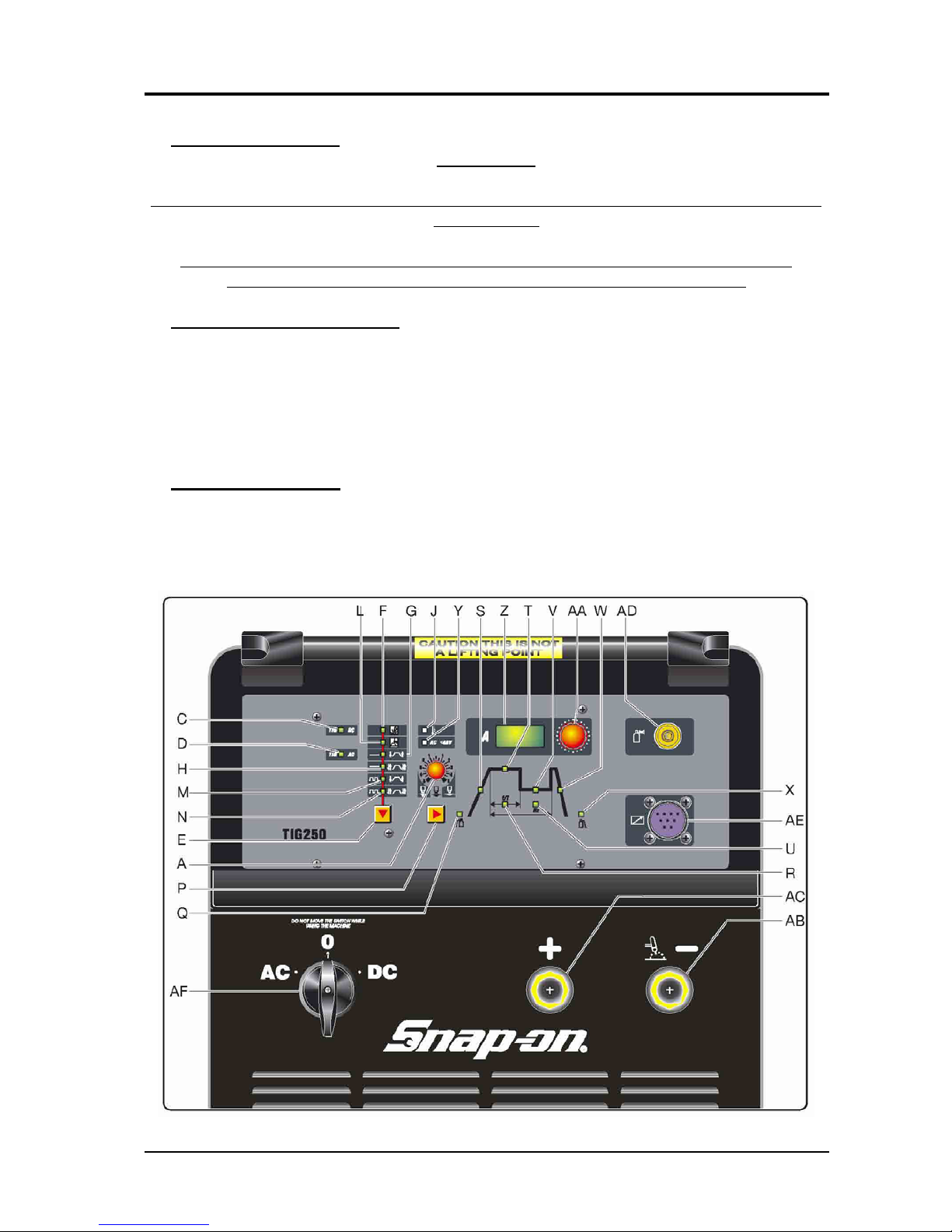
3.2.1 - Control panel commands and signals.
3.302.221 15/01/07
CEBORA S.p.A. 8
NOTE
Operations preceded by this symbol refer to operator actions.
♦ Operations preceded by this symbol refer to machine responses that must occur following an
operator action.
3.2.2 - Power Source TIG operation.
Connect the gas supply to the fitting on the rear panel.
Connect the TIG torch to the negative pole (AB) of the power source.
Connect the cable of the positive pole (AC) of the power source to the workpiece.
Connect the power source to the mains.
Close the switch (15) on the rear panel in the position corresponding to the mains voltage.
♦ System powered.
♦ On control panel all leds and display light on (lamp test).
♦ After one second, display (Z) shows the version of the program inserted into
control board (40) (es.: P01).
Correct?
♦ Subsequently, display (Z) indicates the programmed current; the Mode signaling
are lit as set before the last time the unit was shut off.
NO (see 3.3.1, 3.3.2, 3.3.3).
YES
Press the button (E) several times; the “Mode” selection is repeated in sequence.
Press the button (P) several times; the “Cicle” selection is repeated in sequence.
♦ Each time the button (E) is pressed, the leds G, H, M and N light in sequence,
together with one of leds (F) or (L), that lit alternatively one each other.
Correct?
♦ Each time the start button (P) is pressed, the leds Q, S, T, R, V, U, W and X light
in sequence, according with the “Mode” selected.
NO (see 3.3.3).
YES
WARNINGS
DURING THE FOLLOWING TESTS DO NOT AIM THE TORCH AT PEOPLE OR PARTS
OF THE BODY, BUT ONLY TOWARDS AN OPEN SPACE OR THE WORKPIECE.
DO NOT TRY TO MEASURE THE OUTPUT VOLTAGE DURING THESE STEPS. THE
PRESENCE OF HIGH FREQUENCY MAY DAMAGE THE INSTRUMENT OR THE
POWER SOURCE ITSELF.
With switch AC/DC (30) select the TIG-DC or TIG-AC process.
Use the button (E) to select the TIG-CONTINUOUS with HF, 2-STAGE “Mode”, leds (L)
and (G) lit.
Briefly press the torch start button.
♦ With switch AC/DC (30) in DC position led (C) remains lit and led (D) off. With
switch AC/DC (30) in AC position led (D) remains lit and led (C) off.
3.302.221 15/01/07
CEBORA S.p.A. 9
♦ Gas begins flowing from the torch, for as long as the button is held down.
Correct?
♦ Gas continues to flow from the torch for the duration of the post-gas time set, led
(X) lit, even after the start button is released.
NO (see 3.3.3, 3.3.4, 3.3.5).
YES
Press the start button and hold it down for approximately 5 seconds.
♦ Gas output begins; the high frequency is then generated to start the arc, as well as
the power source output DC voltage (AC voltage is generated only if output
current in present).
Correct?
♦ After approximately three seconds, the output voltage and high frequency are no
longer generated (TIG operation stops if there is no current at the power source
output after start) and the post-gas stage begins.
NO (see 3.3.6, 3.3.7).
YES
Use the knob (AA) to set the current based on the welding you intend to perform.
Move the torch near the workpiece and press the torch trigger.
♦ Begin welding. Turn the knob (AA) or the torch potentiometer to obtain the
current level suitable for the type of welding to be done.
Correct?
♦ During welding display (Z) indicates the welding current.
NO (see 3.3.3, 3.3.8).
YES
Release the torch start button.
♦ The arc shuts off immediately (if long ramp times are not set).
Correct?
♦ Gas continues to flow for the entire post-gas time.
NO (see 3.3.5).
YES
REGULAR OPERATION.
3.302.221 15/01/07
CEBORA S.p.A. 10
3.3
- Troubleshooting.
WARNINGS
ANY INTERNAL INSPECTION OR REPAIRS MUST BE CARRIED OUT BY QUALIFIED
PERSONNEL.
UNPLUG THE POWER SOURCE FROM THE MAINS BEFORE REMOVING THE
PROTECTIVE COVERS AND ACCESSING THE INTERNAL PARTS.
NOTE
The problems the machine may suffer (symptoms) are indicated in boldface.
Operations preceded by this symbol refer to situations that the operator must check into
(
causes).
♦ Operations preceded by this symbol refer to actions that the operator must carry out to solve
problems (solutions).
3.3.1 - The power source does not start, control panel off.
MAINS SUITABILITY TEST.
Correct?
No voltage for mains protection.
NO
YES
♦ Eliminate any short-circuits or insulation losses on the connections between
power cable, switch (15), terminal board (52), transformer (46) primary winding,
services transformer (4), fan (45) and socket (12) on rear panel.
♦ Make sure wiring between mains cable, switch (15) and transformer (46) primary
winding, with particular care to the connections that perform mains voltage
adjustment and between transformer (46) secondary winding and terminals “A” of
scr group (47) and “C8” of switch AC/DC (30). If you find damage connections
restore them, or devices in short-circuit replace them.
♦ Mains not suitable to power the power source (ex.: insufficient installed power).
MAINS CONNECTION TEST.
Correct?
Switch (15), terminals U and W = 230 Vac with both mains at 208 Vac or 230 Vac.
YES
NO
♦ Check power cable and plug and replace if necessary.
♦ Make sure wiring between mains cable, switch (15) and transformer (46) primary
winding, with particular care to the connections that perform mains voltage
adjustment and between transformer (46) secondary winding and terminals “A” of
scr group (47) and “C8” of switch AC/DC (30). If you find damage connections
restore them, or devices in short-circuit replace them.
♦ Check operation of the switch (15), making sure the contacts close in the sequence
shown in the table in the electrical diagram of par. 5.1.
♦ Check mains voltage conditions.
3.302.221 15/01/07
CEBORA S.p.A. 11
CONTROL BOARD (40) POWER SUPPLY TEST.
Control board (40), connector :
− J2, terminals 1 and 2 = 16 Vac, pulse generator synchronization signal for SCR1, SCR2 and
SCR3 on control board (40).
− J3, terminals 2 - 4 - 1 = 16 - 0 - 16 Vac, power supply to internal circuits of control board
(40).
− J3, terminals 5 - 4 - 6 = 8 - 0 - 8 Vac, power supply to microprocessor circuits on control
board (40).
− J5, terminals 1 - 2 = 26 Vac, start command circuit power supply.
− J6, terminals 4 - 5 - 6 = 7 - 0 - 7 Vac, pulse power source supply for SCR2 and SCR3.
− J6, terminals 1 - 2 = 7 Vac, pulse power source supply for SCR1.
Correct?
− J8, terminals 1 - 2 = 30 Vac, protection circuit power supply.
YES
NO
♦ Check the wiring between J2 control board (40) and J4 fuse board (4).
♦ Check the wiring between J3 control board (40) and J1 fuse board (4).
♦ Check the wiring between J5 control board (40) and 26 Vac signal winding of the
transformer (46).
♦ Check the wiring between J6 control board (40) and J2 fuse board (4).
♦ Check the wiring between J8 control board (40) and 30 Vac signal winding of the
transformer (46).
♦ With power source off, temporarily disconnect connectors J2, J3, J5, J6 and J8, on
control board (40) and check the resistance on the following points of control
board (40):
− Conn. J2, terminals 1 - 2 = approximately 900 ohm;
− Conn. J3, terminals 4 - 1 = 4 - 2 = >Mohm;
− Conn. J3, terminals 4 - 5 = 4 - 6 = >Mohm;
− Conn. J5, terminals 1 - 2 = >Mohm;
− Conn. J6, terminals 5 - 4 = 5 - 6 = >Mohm;
− Conn. J6, terminals 1 - 2 = >Mohm;
− Conn. J8, terminals 1 - 2 = >Mohm.
If incorrect replace control board (40).
♦ With power source off, temporarily disconnect connectors J2, J3, J5, J6 and J8, on
control board (40). Power up again and check once more for the presence of
voltage on the connectors of control board (40):
− Conn. J2, terminals 1 - 2 = 16 Vac (fuse F4 on fuse board (4);
− Conn. J3, terminals 4 - 1 = 4 - 2 = 16 Vac (fuse F1 on fuse board (4);
− Conn. J3, terminals 4 - 5 = 4 - 6 = 8 Vac (fuse F1 on fuse board (4);
− Conn. J5, terminals 1 - 2 = 22 Vac;
− Conn. J6, terminals 5 - 4 = 5 - 6 = 7 Vac (fuse F3 on fuse board (4);
− Conn. J6, terminals 1 - 2 = 7 Vac (fuse F2 on fuse board (4);
− Conn. J8, terminals 1 - 2 = 30 Vac.
If incorrect, make sure the fuses F1, F2, F3 on fuse board (4) are intact, or replace
fuse board (4) or service transformer (4) or power transformer (46).
♦ Replace control board (40).
3.302.221 15/01/07

CEBORA S.p.A. 12
3.3.2 - Power source powered, control panel on, fan (45) stopped.
FAN (45) TEST.
Correct?
Fan (45) terminals on terminal board (52) = 230 Vac, with switch (15) closed and mains
voltage both at 208 or 230 Vac.
NO
YES
♦ Make sure that there are no mechanical impediments blocking the fan (45).
♦ With the power source off, temporarily disconnect, the fan (45) terminals from
terminal board (52) and check resistance between terminals of fan (45). Correct
value = 50 ohm approximately. If incorrect replace the fan (45).
♦ Replace the fan (45).
♦ Check the wiring between switch (15), terminal board (52), the wired bridges on terminal
board (52) and fan (45) terminals.
♦ Check connections between transformer (46) primary winding and switch (15).
3.302.221 15/01/07
 Loading...