

Page 1

SWB 100
WHEEL BALANCER
EQUILIBREUSE DE ROUES
RADAUSWUCHTMASCHINE
•OPERATOR’S MANUAL
•NOTICE D’ UTILISATION
•BETRIEBSANLEITUNG
Page 2
ii
Snap-on Equipment Srl a unico socio
Via Provinciale per Carpi, 33
42015 CORREGGIO (RE) ITALY
Tel.: +39-(0)522-733480
Fax: +39-(0)522-733479
E-mail: corrcs@snapon.com
Internet: http://www.snapon-equipment.eu
EC DECLARATION (Original document contained in Spare Parts Booklet)
DECLARATION CE (Le document original fi gurant dans le Liste des pièces détachées)
CE KONFORMITÄTSERKLÄRUNG (Originaldokument in der Ersatzteilliste enthaltenen)
ДЕКЛАРАЦИЯ EC (Оригинал документа прилагается к ведомости запчастей)
DICHIARAZIONE CE (Originale contenuta nel Libretto Ricambi)
DECLARACIÓN CE (El original se encuentra en tabla de repuestos)
DECLARAÇÃO CE (O original está contida em Lista de peças)
- FACSIMILE -
- ФАКСИМИЛЕ -
ENG - DECLARATION OF CE CONFORMITY
FRA - DECLARATION CE DE CONFORMITE
DEU - KONFORMITÄTSERKLÄRUNG
FIN - EY-VAATIMUSTENMUKAISUUSVAKUUTUS
NLD - VERKLARING VAN OVEREENSTEMMING
SWE - EG-FÖRSÄKRAN OM ÖVERENSSTÄMMELSE
DAN - EF-OVERENSSTEMMELSESERKLÆRING
ISL - EB-SAMRÆMISYFIRLÝSING
POL - DEKLARACJA ZGODNO•CI “CE”
RUM - DECLARA•IE DE CONFORMITATE CU NORMELE CE
SLO - ES VYHLÁSENIE O ZHODE
SLV - IZJAVA O SKLADNOSTI CE
ALB - DEKLARATË KONFORMITETI KE
HUN - EK MEGFELEL•SÉGI NYILATKOZAT
DICHIARAZIONE CE DI CONFORMITA’ - ITA
DECLARAÇÃO CE DE CONFORMIDADE - POR
DECLARACIÓN CE DE CONFORMIDAD - SPA
•••!"#"$%& '" ( )*+,•+(+,%• - BUL
ES PROHLÁŠENÍ O SHOD. - CES
DEKLARACIJA CE O PODOBNOSTI - HRV
EÜ VASTAVUSDEKLARATSIOON - EST
/01230 CE 34556782303 - ELL
ES ATBILST9BAS DEKLAR: CIJA - LAV
ATITIKTIES DEKLARACIJA - LIT
“EC” •••!"#"$%;" '" ( **<# "'=*( + - MKD
DEKLARACIJA CE O USKLA>ENOSTI - MON
EC UYGUNLUK BEYANNAMES? - TUR
•••!"#"$%& ( **+,•+(+,%& ( +" =•" #+" @ •( -
RUS
Snap-on Equipment Srl - Via Provinciale per Carpi, 33 - 42015 Correggio (RE) Italy
ENG - takes full responsibility for declaring that the machineQ
FRA - déclare sous sa propre responsabilité que la machine Q
DEU - erklärt auf eigene VerantwortungX dass die MaschineQ
ITA - dichiara sotto la propria responsabilità che la macchinaQ
POR - declara sob a própria responsabilidade que a máquinaQ
SPA - declara bajo su propia responsabilidad que la máquinaQ
ALB - deklaron nën përgjegjësinë e tij se makineriaQ
BUL - [\] ^_`v`_ xz [ z {| z} z`~z€{X ‚\ ƒ_„v~_{_Q
CES - prohlašuje na …lastní †odpo…‡dnostX že strojní †aˆí†eníQ
HRV - i†ja…ljuje pod …lastitom odgo…ornoš‰u da strojQ
DAN - erklærer på eget ans…arX at maskinenQ
EST - kinnitab omal …astutuselX et aparaatQ
FIN - …akuuttaa omalla …astuullaanX että koneQ
ELL - ‹ŒŽ‘•–— ˜™–›œ˜•Ÿ ¡— Œ ¢Œ£Ÿ•¤Q
ISL - lýsir þ…í y¥ r á eigin ábyrgð að bíllinnQ
LAV - ap†in¦damies sa…u atbild§bu apliecinaX ka maš§na¨iek¦rtaQ
LIT - prisiimdama atsakomyb© skelbiaX kad mašinaQ
MKD - vª«_}¬}_ xz[ €}z «_ z[ |z} z`~z€{ [\]_ ƒ_„v~_{ _Q
MON - i†ja…ljuje pod …lastitom odgo…oroš‰u da mašinaQ
NLD - …erklaart …oor eigen …erantwoordelijkheid dat de machineQ
POL - o-wiadc†a na w®asn¯ odpowied†ialno-‰X °e mas†ynaQ
RUM - declarã pe propria rãspundere cã ma±inaQ
SLO - …yhlasuje na …lastnú †odpo…ednos²X že strojo…é †ariadenieQ
SLV - pod lastno odgo…ornostjo i†ja…ljamoX da je strojQ
SWE - försäkrar under eget ans…ar att maskinenQ
TUR - kendi sorumlulu³u alt´nda makinenin a±a³´da belirtilen yönetmeliklere uygun oldu³unu beyan etmektedirQ
HUN - a saját felelµssége tudatában kijelentiX hogy a gépQ
RUS - € xz^~z¶ z{} \ {€{}\~~z€{·¸ ª_¹}^¹\ { ‚{z ƒ_„v~_
WHEEL BALANCER
EQUILIBREUSE
RADAUSWUCHTGERÄT
EQUILIBRATRICE
MÁQUINA DE EQUILIBRAR RODAS
EQUILIBRADORA
EKUILIBRUESE
!"#$%" &" '"("%)$*"%+ %" ,.!$
VYVAŽOVA/KA
BALANSER
HJULAFBALANCERINGSMASKINE
TASAKAALUSTUSSEADE
TASAPAINOTUSKONE
0123455467873
JAFNVÆGISSTILLINGARVÉL
BALANSÇÐANA
BALANSAVIMAS
$&+9%":.;":
BALANSERKA
BALANCEERMACHINE
WYWA<ARKA
ECHILIBROR
VYVAŽOVA/KA
STROJ ZA URAVNOTEŽEVANJE
BALANSMASKIN
DENGELEY=C=
KERÉKKIEGYENSÚLYOZÓ
'"("%)$*>;>:%?@ )X+%9
Correggio (RE) - ITALYFrancesco Frezza
date:
FRA - est conforme à toutes les dispositions pertinentes des directives suivantes :
DEU - Allen zu folgenden Richtlinien gehörenden Bestimmungen entspricht:
ITA - è conforme a tutte le disposizioni pertinenti delle seguenti direttive:
POR - satisfaz todas as disposições relevantes das seguintes directivas:
SPA - es conforme con todas las disposiciones pertinentes a las siguientes directivas:
ALB - është konform me të gjitha dispozitat që kanë të bëjnë me direktivat e mëposhtme:
BUL - ••••••••••! "! ••#$%# &!'(•&•)*#, ••)•&+!.# •• • •/•)•!.#•• )#&•%•#•#:
CES - vyhovuje všem požadavk0m, které se vztahují na následující sm1rnice:
HRV - udovoljava svim relevantnim odredbama slijede2ih smjernica:
DAN - er i overensstemmelse med bestemmelserne i følgende direktiver:
EST - vastab järgmiste direktiivide kõikidele asjassepuutuvatele sätetele:
FIN - on seuraavien direktiivien asiaankuuluvien säännösten mukainen:
ELL - 34567 89;<=5> ;3 ?@3J K7J MQ>W@XY37J 8Z3K7[XJ ;3 K7J 6[?@>\]3J >^_`43J:
ISL - er í samræmi við allar viðeigandi tilskipanir eftirfarandi reglugerða:
LAV - atbilst visiem attiecxgajiem noteikumiem š{d{s direktxv{s:
LIT - atitinka visus toliau nurodyt| direktyv| reikalavimus:
}~D - • •• ••€/!•"••• •• •#•• "•&‚# •) •/•)"#•• )#&•%•#•#:
}ON - je u skladu sa svim relevantnim odredbama slede2ih direktiva:
NLD - overeenstemt met alle toepasselijke voorschriften van de volgende richtlijnen:
POL - jest zgodna ƒjest zgodny„ ze wszystkimi zarz…dzeniami zawartymi w nast†puj…cych dyrektywach:
RU} - este fabricat în conformitate cu toate prevederile în materie din urmãtoarele directive:
SLO - vyhovuje všetkým požiadavkám, vz‡ahujúcim sa na nasledujúce smernice:
SLV - v skladu z vsemi predpisi, ki se nanašajo na naslednje direktive:
SˆE - överensstämmer med alla bestämmelser tillhörande följande direktiv:
TUR - a‰aŠ‹da belirtilen yönetmeliklere ili‰kin tüm hükümlere uygundur:
HUN - megfelel a következŒ irányelvekbe foglalt, valamennyi rendelkezésnek:
RUS - ••••••••••Ž•• •••‚ (&#‚•"‘•‚’‚ "•&‚!‚ •/•)Ž“.#” )#&•%•#•:
ENG-The } anager of the Technical Of• ce is authorised to compile a technical lea– et in compliance with appendi— VII, letter A, of the ˜™™›œŸ˜œCE directive
FRA-Le Responsable du Bureau Technique est autorisé à constituer le fascicule technique visé sous l¡anne—e VII lettre A de la directive ˜™™›œŸ˜œCE
DEU-DerLeiterdertechnischenAbteilungistbevollmächtigt,dietechnischenUnterlagenzuerstellenƒsieheAnhangVII,BuchstabeAderRichtlinie˜™™›œŸ˜œCE
ITA-Il Responsabile dell¡Uf•cio Tecnico è autorizzato a costituire il fascicolo tecnico di cui all¡allegato VII lettera A della direttiva ˜™™›œŸ˜œCE
POR-O Responsável do Gabinete Técnico está autorizado a compilar o processo técnico, referido no ane—o VII alínea Ada directiva ˜™™›œŸ˜œCE
SPA-ElResponsabledelDepartamentoTécnico estáautorizadoa constituirelfascículo técnicoindicadoen elane—oVII letraA dela directiva˜™™›œŸ˜œCE
ALB-Përgjegjësi i ¢yrës Teknike është i autorizuar të realizojë fashikullin teknik sipas dokumentit bashkëngjitur VII germa Ae direktivës ˜™™›œŸ˜œ~E
BUL-£•€•••&" #%••" ! ¤•”"#$••%#‘••) •/ •Ž( •/ "•‚•. •" )! ••••!•# ••”"#$••%! •! *&•¥ Ž&! •••••••••••#••¦ &#/•+•" #•VII,§A¨,©#&•%•#•! ˜™™›œŸ˜œEª
CES-¢odpov1dný pracovník technického odd1lení je oprávn1ný vypracovat technickou dokumentaci podle p«ílohy VII ¬ásti ASm1rnice ˜™™›œŸ˜œES
HRV-Odgovorna osoba Tehni¬kog ureda je ovlaštena ustroji ti tehn i¬ki svezak kako se vidi u dodatku VII slovo A smje rnice ˜ ™™›œŸ˜œCE
DAN-Chefen i den tekniske afdeling har t illadelse til udarbejdelse af den te kniske dokumentat ion jf bilag VII litra A i direktivet ˜™™›œŸ˜œEF
EST-Te hnoos akon na vas tuta v tööt aja on voli tatu d koos tama t ehni lise t oimi ku vas taval t dir ektii vi ˜™™ ›œŸ˜ œEÜ VI I lisa osal e A
FIN-Teknisen toimiston vastuuhen kilö on valtuut ettu koko amaan te kninen er itelmä di rektiivin ˜™™›œŸ˜œE- li itteen V II kohdan A m ukaisesti
ELL-®¯M39] \5>JK>\ °3Z57[>9±Q6<34>\ 345673²>\ 87>^>K_;X5>J56 M6Q³ ² 37K>5K3Z57[ ?< ³[ 3@>89; <= 56; 3K> 8\ 5_;; X5>VII` Q³ ; ; 6AK_J>^_`46J ˜™™›œŸ˜œ´ µ
ISL- Ábyr gðar mann i tæk nisk rifs tofu nnar e r hei milt a ð ger a t ækni skja lið s amkv æmt A-l ið VI I við auka í reg luge r𠘙 ™›œŸ ˜œEB
LAV-Tehnisk{s noda¶as vadxt{ js ir pilnvaro ts sast{ dxt teh nisko do kument{ ciju atbilstoši ES direktxvas ˜™™ ›œŸ˜œE~ VII pielikuma A ie da¶ai
LIT-užtechnin·skyri| atsakingasasmuo yra·galiotassudaryti technin†byl…, kuriossudarymo tvarkanurodyta Direktyvos˜™™›œŸ˜œEBVII priedoA dalyje
} ~D-£ )€•••&"#•• " ! ••”" #$%#•• •)) •/ • ••/ !•••" ) ! €• ••••! •#••”" #$%#•• (&#&!$" #%) ! )•" ••( &#/•€VII ( #•‚•A•) ) #&•%•#•! •! ˜™™›œŸ˜œCE
} ON-Odgovorno lice Tehni¬kog ured a je ovlašteno da sastavi tehni¬ku fasciklu kako se vidi u dodatk u VII slovo A direkt ive ˜™™›œ Ÿ˜œCE
NLD-HetHoofdvandeTechnischeAfdelingisgemachtigdomhettechnischdossiersamentestellenwaaroverinBijlageVII,afdelingA, vanderichtlijn˜™™›œŸ˜œEG
POL-~ierownikBiuraProjektowegojestupowa¸nionydo za¹o¸eniaskoroszytutechnicznego,októrym mowaw¢a¹…cznikuVIIliteraAdyrektywy˜™™›œŸ˜œUE
RU} -ResponsabilulBirouluiTehnicesteautorizatsãîntocmeascãdosarultehnicprevãzutînane—aVIIliteraAdirectiva˜™™›œŸ˜œCEprivindechipamenteletehnice
SLO-¢odpovedný pracovníktechnického oddelenia jeoprávnený vypracova‡ technickúdokumentáciu podºaprílohy VII ¬astiA Smernice˜™™›œŸ˜œES
SLV-Vodja tehniè nega urada je poo blašèena za s estavo tehn iène mape, kot na vedeno v pril ogi VII, èrka A di rektive ˜™™› œŸ˜œES
SˆE-AnsvarigpådettekniskakontoretharbehörighetattsammanställamedföljandetekniskdokumentationienlighetmedavsnittAibilagaVIIi direktiv˜™™›œŸ˜œEG
TUR- Teknik Ofis Sor umlus u ˜™™› œŸ˜œ EC - ö netm eliŠi ¡nin VI I eki nin A har finde bel irtil en te knik d osyay ‹ haz ‹rlam aya ye tkil idir
HUN-A} »szaki IrodaIrodavezetŒjefeljogosította˜™™›œŸ˜œE~ irányelvArészénekVII } ellékletébenmeghatározott,m»szakidokumentációösszeállítására
RUS-¼Ž%•••)#••/½ ••”"#$••%•€• ••)•/! Ž(•/"•‚•$•" ••••!•#•½ ••”"#$••%#¾ /#•• • ••••••••••## • (&#/•+•"#•‚ VII, /#••& A )#&•%•#•’ ˜™™›œŸ˜œCE
ITA-Direttore Operativo SPA-Director Operativo POR-Director Operacional ENG-Operations } anager FRA-Directeur Opérationnel
DEU-Betriebsleiter ALB-Drejtori Operativ BUL-£(•&!•#••" )#&•%••& CES-Výkonný «editel HRV-Operativni direktor DAN-Driftsleder
EST-TegevdirektorFIN-Operatiivinen johtajaELL-´ M7Z37Q_876[ ?J ¿73\ ] \ 5KÀJISL-Starfandi framkvæmdarstjóri LAV-Operatxvais direktors
LIT-Operacij| vadovas }~D-£(•&!•#••" )#&•%••& }ON-Operativni direktor NLD-Operationeel directeur POL-Dyrektor Operatywny
RU}-Director Operator SLO-Výkonný riaditeº SL V-Operativni vodja SˆE-Driftledare TUR-‰letme }üdürü HUN-Operatív Igazgató
RUS - Ã(&!•/‘“.#¾ (&•#'••)••••‚
2006/42/CE
2014/35/CE
2014/30/CE
All Information in this manual has been supplied by the producer of the equipment:
Toutes les informations fi gurant dans le présent manuel ont été fournies par le fabricant de l’équipement :
Alle in diesem Handbuch enthaltenen Informationen wurden durch den Hersteller der Maschinen geliefert:
Вся информация, содержащаяся в данном руководстве, предоставлена производителем оборудования
Tutte le informazioni contenute nel presente manuale sono fornite dal produttore dell’apparecchiatura:
Todas las informaciones contenidas en este manual han sido facilitadas por el productor del equipo:
Todas as informações contidas neste manual foram fornecidas pelo produtor da máquina:
SWB 100
SWB 100
BRAND
Page 3
iii
DICHIARAZIONE CE
EC DECLARACIÓN CE
DECLARAÇÃO CE
Schema Elettrico
WD Esquema Eléctrico
Esquema Eléctrico
Contenuto in SP
Integradas en SP
Conteúdos em SP
Contained in SP
Teil der SP
Contenu dans SP
Содержится в каталоге запчастей
EC DECLARATION
EC CE KONFORMITÄTSERKLÄRUNG
DECLARATION CE
ДЕКЛАРАЦИЯ ЕС
Wiring Diagram
WD Schaltplan
Schéma électrique
Схема электрических соединений
NOTE SULLA DOCUMENTAZIONE - ITA
NOTAS SOBRE LA DOCUMENTACIÓN - SPA
NOTAS SOBRE A DOCUMENTAÇÃO - POR
ENG - NOTES REGARDING DOCUMENTATION
DEU -
ANMERKUNGEN ZUR DOKUMENTATION
FRA - NOTES SUR LA DOCUMENTATION
RU - ПРИМЕЧАНИЯ ПО ДОКУМЕНТАЦИИ
DOCUMENTAZIONE DISPONIBILE
DOCUMENTAÇÃO DISPONÍVEL
DOCUMENTACIÓN DISPONIBLE
DOCUMENTATION AVAILABLE
DOCUMENTATION DISPONIBLE
VERFÜGBARE DOKUMENTATION
ДОСТУПНАЯ ДОКУМЕНТАЦИЯ
Pubblicazione di supporto al prodotto:
EQUILIBRATRICE
Publicación de soporte al producto:
EQUILIBRADORA
Documentação de apoio ao produto:
MÁQUINA DE EQUILIBRAR RODAS
edizione di lingua originale in: ITALIANO
edición original en idioma: ITALIANO
edição original em: ITALIANO
Data di prima pubblicazione:
Fecha de la primera publicación:
Data da primeira publicação:
Product aid publication:
WHEEL BALANCER
Zum Produkt gehörendes Dokument:
AUSWUCHTMASCHINEN
Publication de support au produit:
EQUILIBREUSE
Публикация для поддержки изделия:
БАЛАНСИРОВОЧНЫЙ СТАНОК
original language edition in: ITALIAN
Originalausgabe in: ITALIENISCH
langue d’origine de la publication: ITALIEN
оригинального издания: итальянский
Date of fi rst publication:
Datum der Erstveröffentlichung:
Date de la première édition:
дата первого издания:
06 / 2016
06 / 2016
SWB 100
ABB. DESCRIPTION CODE LANGUAGE
SIGLE DESCRIPTION CODE LANGUE
KENN. BESCHREIBUNG CODE SPRACHE
Operator’
s Manual
Manuel de l’Opérateur ZEEWB117A03
ENG-FRA-DEU
OM Betriebsanleitung
Руководство по эксплуатации
ZEEWB117A08 RU
Spare Parts Booklet ENG-FRA-DEU
SP Liste des pièces détachées TEEWB117A3 ITA-SPA-POR
Ersatzteilliste RU
Safety Booklet (Quick Start) EAZ0103G25A
ENG-FRA-DEU
QS Manuel de Securité EAZ0103G26A ITA-POR-SPA
Sicherheitsvorkehrungen EAZ0103G27A RU
SIGLA DESCRIZIONE CODICE LINGUA
SIGLA DESCRIPCIÓN CÓDIGO IDIOMA
SIGLA DESCRIÇÃO CÓDIGO IDIOMA
Manuale Operatore
OM Manual de Operador ZEEWB117A05 ITA-SPA-POR
Manual do Operador
Libretto Ricambi ENG-FRA-DEU
SP tabla de repuestos TEEWB117A3 ITA-SPA-POR
Lista de peças RU
Libretto di Sicurezza EAZ0103G25A
ENG-FRA-DEU
SB Manual de Seguridad EAZ0103G26A ITA-POR-SPA
Manual de Segurança
EAZ0103G27A RU
Page 4

iv
UPDATING REPORTS
DISCLAIMER OF WARRANTIES
AND LIMITATIONS OF LIABILITIES
While the authors have taken care in the preparation
of this manual, nothing contained herein:
- modifi es or alters in any way the standard
terms and conditions of the purchase, lease or
rental agreement under the terms of which the
equipment to which this manual relates was
acquired,
- increases in any way the liability to the customer
or to third parties.
TO THE READER
While every effort has been made to ensure that
the information contained in this manual is correct,
complete and up-to date, the right to change any part
of this document at any time without prior notice is
reserved.
Before installing, maintaining or
operating this unit, please read
this manual carefully, paying extra
attention to the safety warnings
and precautions.
Table of Contents
Table of contents iv
1.0 Safety 6
2.0 Speci! cations 8
3.0 Introduction 10
4.0
Layout 14
5.0 Operation 22
6.0 Maintenance 74
7.0
Trouble shotting 76
8.0 Disposing of the unit 88
9.0 Appendix 88
Appendix: Installation Instructions 91
Revision A
of June 2016
First document issue PCN: 16G0160
Page 5

v
Inhaltsverzeichnis
Inhaltsverzeichnis v
1.0 Sicherheit 7
2.0 Spezi! kationen 9
3.0
Einfürung 11
4.0 Layout 15
5.0 Betrieb 23
6.0 Wartung 75
7.0 Fehlerbeseitigung 77
8.0 Entsorgung 89
9.0 Anhang 89
Anhang: Installationsanweisugen 91
GEWÄHRLEISTUNGS- UND
HAFTUNGSAUSSCHLUSS
Die Informationen in dieser Bedienungsanleitung wurden
gewissenhaft und sorgfältig zusammengestellt. Der Inhalt
oder Teile des Inhalts dieser Bedienungsanleitung:
- haben keinen Einfluß auf die Allgemeinen
Geschäftsbedingungen des Kaufvertrages,
Leasingvertrages oder Mietvertrages auf dessen
Grundlage das in dieser Bedienungsanleitung
beschriebene Maschine bezogen wurde,
- erweitern in keiner Weise den Haftungsanspruch
des Kunden oder Dritter.
AN DEN LESER
Be i d er Zu sa m me ns t el lu n g d er in di es er
Bedienungsanleitung enthaltenen Informationen wurde
größten Wert auf deren Richtigkeit, Vollständigkeit und
Aktualität gelegt. Wir behalten uns jedoch ausdrücklich
das Recht vor, diese Informationen jederzeit und ohne
vorherige Ankündigung zu ändern.
Lesen Sie diese
Bedienungsanleitung sorgfältig
durch, bevor Sie die Maschine
installieren, warten oder betreiben.
Beachten Sie insbesondere die
Sicherheitsvorschriften und
Warnungen.
LIMITES D’APPLICATION DE LA GARANTIE ET
LIMITATIONS DE LA GARANTIE
Bien que les auteurs aient accordé la plus grande
attention à la rédaction du présent manuel, aucun
élément fi gurant dans ce dernier:
- ne modifi e les conditions et les termes standards
d’un accord d’achat en crédit-bail ou de location,
aux termes desquels les appareils traités dans
le présent manuel sont achetés,
- ou n’augmente la responsabilité de la société
envers le client ou les tiers.
POUR LE LECTEUR
Bien que tout effort ait été fait pour assurer l’exactitude
des informations fi gurant dans le présent manuel,
comme complément ou mise à jour de ce dernier, le
droit d’y apporter des modifi cations à tout moment sans
préavis est réservé.
Avant d’installer, d’entretenir ou d’uti-
liser la machine, lire attentivement le
présent manuel, en faisant particuliè-
rement attention aux avertissements
et précautions de sécurité.
Table des matieres
Table des matieres v
1.0 Sécurité 7
2.0 Speci!
cations 9
3.0 Introduction 11
4.0 Disposition 15
5.0
Utilisation 23
6.0
Entretien 75
7.0 Dépannage 77
8.0 Vente 89
9.0 Annexes 89
Annexe: Instructions d’Installation 91
Page 6

6
1-1
WICHTIG!! DIESE ANLEITUNG IST
AUFZUBEWAHREN
IMPORTANT!! CONSERVER LES
PRÉSENTES INSTRUCTIONS
Safety
IMPORTANT!! SAVE THESE
INSTRUCTIONS
1.0 Safety
Important safety precautions relevant to the unit are
described in the Safety Booklet, refer to Figure 1 – 1.
The Safety Precautions should be fully understood and
observed by every operator. We suggest you store (a
copy) of the Safety Booklet near the unit, within easy
reach of the operator.
The Operator’s Manual will contain specifi c warnings
and cautions when dangerous situations may be
encountered during the procedures described.
1.1 Typographical conventions
This manual contains text styles intended to make the
reader pay extra attention:
Note: Suggestion or explanation.
CAU
TION: INDICATES THAT THE FOLLOWING
ACTION MAY RESULT IN DAMAGE TO THE UNIT
OR OBJECTS ATTACHED TO IT.
WARNING: INDICATES THAT THE FOLLOWING
ACTION MAY RESULT IN (SERIOUS) INJURY TO
THE OPERATOR OR OTHERS.
• Bulleted list:
• Indicates that action must be taken by the operator
before proceeding to the next step in the sequence.
TOPIC (F n°) = see the Chapter number.
The topic indicated is explained in full in the charter
specifi er.
1.2 Manuals for the unit
The unit includes the following documentation:
- Safety Booklet (standard supplement , Fig. 1-1)
- Operator’
s Manual
The operator must learn in detail the instructions
contained in them and meticulously observe the
notes HAZARD and CAUTION WARNINGs.
- Spare Parts Booklet
Document used only by the Technical Support staff.
Installation instructions
The installation instructions are in the Appendix of
the Operator Manual.
EC Declaration of Conformity
The EC Declaration is included in the Spare Parts
Booklet.
P/N: EAZ0103G25A
Page 7

7
Sicherheit
1.0 Sicherheit
Wichtige Sicherheitsmaßnahmen für dieses Gerät
sind im Sicherheitshandbuch beschrieben; siehe
Abbildung 1-1.
Die Sicherheitsmaßnahmen müssen von allen
Bedienern verstanden und eingehalten werden.
Wir empfehlen, eine Kopie des Sicherheitshefts in
der Nähe des Geräts gut sichtbar für den Bediener
aufzubewahren.
Das Bedienungshandbuch enthält spezifische
Warnungen und Hinweise, wenn bei den beschriebenen
Maßnahmen gefährliche Situationen auftreten können.
1.1 Typographie
Dieses Handbuch enthält Schriftweisen, die zu
besonderer V
orsicht auffordern:
Anmerkung:
Vorschlag oder Erklärung
VORSICHT: WEIST DARAUF HIN, DASS DIE
FOLGENDE MASSNAHME ZU SCHÄDEN AM
GERÄT ODER DARAN BEFESTIGTEN TEILEN
FÜHREN KANN.
WARNUNG: WEIST DARAUF HIN, DASS DIE
FOLGENDE MASSNAHME ZU (SCHWEREN)
VERLETZUNGEN DES BEDIENERS ODER
ANDERER PERSONEN FÜHREN KANN.
• Aufzählungspunkte:
• Zeigen an, dass der Bediener Maßnahmen
durchführen muss, bevor er zum nächsten Schritt
des Vorgangs übergehen kann.
THEMA F Nr. (= siehe Kapitel Nummer).
Das angegebene Thema wird in dem bezeichneten
Kapitel ausführlich behandelt.
1.2 Handbücher des Geräts
Das Gerät ist mit folgender Dokumentation ausgestatt
et:
-
Sicherheitsheft (Standardbeilage, Abb. 1-1).
- Betriebsanleitung
Der Benutzer muss die da r i n enthaltenen
Anweisungen im Detail erfassen und die Hinweise,
die WARNUNGEN vor Gefahren und die Angaben
mit der Bezeichnung ACHTUNG genauestens
befolgen.
- Ersatzteilhandbuch
Dieses Dokument ist dem Wartungspersonal
vorbehalten.
Installationsanweisungen
Die Installationsanweisungen fi nden Sie in der
Anlage der Betriebsanleitung.
CE-Konformitätserklärung
Die CE-Konformitätserklärung befi ndet sich im
Ersatzteilhandbuch.
Sécurité
1.0 Sécurité
Les mesures de sécurité importantes relatives à l’unité
sont décrites dans le Livret de Sécurité et résumées
Figure 1-1.
Chaque opérateur doit totalement comprendre les
mesures de sécurité. Nous suggérons de conserver
une copie du Livret de Sécurité près de la machine à
la portée de l’opérateur.
Le Manuel de l’Opérateur contient des avertissements
et des mesures de prudence spécifiques à des
situations potentiellement dangereuses qui peuvent
se produire durant les procédures décrites.
1.1 Typographie
Ce manuel contient des styles de texte qui vous
demande de prêter une attention particulière :
Remarque : Suggestion ou explication.
ME
SURE DE PRUDENCE : INDIQUE QUE L’ACTION
SUIVANTE RISQUE D’ENDOMMAGER LA MACHINE
ET DES OBJETS ATTACHES A LA MACHINE.
AVERTISSEMENT : INDIQUE QUE L’ACTION
SUIVANTE RISQUE DE CAUSER DES BLESSURES
(SERIEUSES) A L’OPERATEUR OU AUTRES.
• Liste à puces :
• Indique que l’opérateur doit effectuer une action
avant de pouvoir passer à l’étape suivante de la
séquence.
ARGUMENTO (F n°) = ir para o número do capítulo.
A actualização indicada è tratada dentro do capítulo
especifi cado.
1.2 Manuels de la machine
La machine est accompagnée des manuels suivants:
-
Livret de Sécurité
(supplément de norme, Fig. 1-1)
- Manuel d’utilisation (Chapitre 1 – 9) L’utilisateur
doit apprendre dans le détail les instructions que
ce manuel contient et observer scrupuleusement
les remarques, les MISES EN GARDE de danger
et d’ATTENTION
-
Tables et Listes des Pièces de Rechange Document
à usage exclusif du personnel d’assistance.
Instructions pour l’installation
Les instructions pour l’Installation se trouvent dans
l’Appendice du Manuel d’utilisation.
Déclaration de Conformité CE
La Déclaration CE fi gure dans la Notice des Pièces
détachées.
Page 8

8
230V~, 50/60 Hz, 1 ph
1,1 A
0,12 KW
(2x)IEC 127 T 6,3A
>6 sec.
<100 rpm
0–250 mm
1/5 g o 0,05/0,25 oz
20” (508 mm)
35” (900 mm)
70 Kg (154 lbs)
1-20” (25-508mm)
8-25”
8-32”
40 mm
70 Kg
90 Kg
1711x1005x1100 mm
1180x940x760 mm
<70 db(A)
0-50 °C
10-90%
Specifi cations
2.0 Speci! cations
Power:
Power Supply
Power consumption
Motor rating
Mains fuses
Measurements:
Measuring time
Measuring speed
O
ffset
Resolution
Wheel dimensions:
Max. width
Max. diameter
Max. weight
Rim width
Rim diameter:
NORMAL, ALU, ST
ATIC
Manual
Shaft:
Stub shaft diameter
Dimensions:
Weight
Shipping weight
Max. Dimensions (hxdxw)
Shipping dimensions
Miscellaneous:
Noise level
2.1 Conditions
During use or long term storage, the conditions shou
ld
never exeed:
Temperature range
Humidity range
non condensing
Page 9

9
230V~, 50/60 Hz, 1 ph
1,1 A
0,12 KW
(2x)IEC 127 T 6,3A
>6 sec.
<100 rpm
0–250 mm
1/5 g o 0,05/0,25 oz
20” (508 mm)
35” (900 mm)
70 Kg (154 lbs)
1-20” (25-508mm)
8-25”
8-32”
40 mm
70 Kg
90 Kg
1711x1005x1100 mm
1180x940x760 mm
<70 db(A)
0-50 °C
10-90%
230V~, 50/60 Hz, 1 ph
1,1 A
0,12 KW
(2x)IEC 127 T 6,3A
>6 sec.
<100 rpm
0–250 mm
1/5 g o 0,05/0,25 oz
20” (508 mm)
35” (900 mm)
70 Kg (154 lbs)
1-20” (25-508mm)
8-25”
8-32”
40 mm
70 Kg
90 Kg
1711x1005x1100 mm
1180x940x760 mm
<70 db(A)
0-50 °C
10-90%
Spezifi kationen
2.0 Spezi• kationen
Strom:
Stromversorgung
Stromverbrauch
Motorwerte
Netzsicherungen
Daten:
Messzeit
Messdrehzahl
Abstand Maschine/Felgenhorn
Aufl
ösung
Radmaße:
Max. Breite
Max. Durchmesser
Max. Gewicht
Felgenbreite
Felgendurchmesser:
NORMAL,
ALU, STATISCH
Manuell
Welle:
Hauptwellendurchmesser
Maße:
Gewicht
Versandgewicht
Max. Maße (HxTxB)
Versandmaße
Anderes:
Geräuschpegel
2.1 Bedingungen
Während der Benutzung bzw. einer Langzeitlagerung
d
ür
fen die folgenden Werte nicht überschritten werden.
Temperaturbereich
Luftfeuchtigkeitsbereich
nicht kondensierend
Specifi cations
2.0 Speci• cations
Données électrices :
Alimentation
Consommation électrique
Puissance moteur
Fusibles
Mesures :
Durée des mesures
V
itesse rotation
Ecart
Résolution
Dimensions de roue :
Largeur max.
Diamètre max.
Poids max.
Largeur de la jante
Diamètre de la jante:
NORMAL, ALU, ST
ATIQUE
Manuel
Arbre :
Diamètre de bout d’arbre
Misure:
Poids
Poids d’expédition
Dimensions max. (hxdxl)
Dimensions d’expédition
Divers :
Niveau sonore
2.1 Conditions
Lors d’une utilisation ou un stockage prolongé les
conditions ne doivent jamais dépasser :
Gamme de températures
Gamme d’humidité
sans formation de buée
Page 10

10
Introduction
3.0 Introduction
This wheel balancer combines advanced, highper
formance technology, robustness and reliability with
very simple, user-friendly operation.
The low rotation speed of the wheel ensures that this
balancer is very safe.
It is characterised by a display and input panel which
are easy to use and guarantee rapid, intuitive operation.
Operator time and effort are reduced to a minimum,
while maintaining accuracy and reliability.
Always work in a clean area and with clean wheels,
no dirt stuck in the tyre or on the rim. That way proper
mounting of the wheel and an optimal balancing result
can be achieved.
Application
The off-the-vehicle wheel balancer is designed for
dynamic and static balancing of passenger car and
light-truck wheels, that fall within the limits stated in
the technical specifi cations.
This is a high accuracy measuring device. Handle
with care.
Page 11

11
Einführung
3.0 Einführung
Dieses Auswuchtgerät verbindet hochmoderne
Hoc
hleistungstechnik, Robustheit und Zuverlässigkeit
mit einfachem, benutzerfreundlichem Betrieb.
Durch die niedrige Rotationsgeschwindigkeit des
Rades ist das Auswuchtgerät extrem sicher in der
Benutzung.
Es ist mit einem einfach zu benutzenden Displayund Eingabefeld ausgestattet, was eine schnelle und
intuitive Benutzung gewährleistet.
Die Bedienungszeit und der Bedienungsaufwand
sind auf ein Minimum reduziert, ohne jedoch die
Genauigkeit und die Beständigkeit zu beeinträchtigen.
Arbeiten Sie immer in einer sauberen Umgebung
und mit sauberen Rädern, an denen weder an Reifen
noch an der Felge Schmutz klebt. Auf diese Weise ist
sichergestellt, dass das Rad richtig aufgespannt wird
und eine optimale Auswuchtung erzielt wird.
Einsatzbereich
Das Auswuchtgerät für demontierte Räder wurde zur
statischen und dynamischen Auswuchtung von Rädern
von Personenkraftwagen und leichten Lkws entwickelt,
die in den Bereich der angegebenen technischen
Spezifikationen fallen. Dies ist ein hochgenaues
Messgerät. Behandeln Sie es pfl eglich.
Introduction
3.0 Introduction
Cette équilibreuse vous offre une technologie avancé
e
de haute performance, solidité et fiabilité et son
opération est très simple et conviviale.
La faible vitesse de rotation de la roue assure que
cette équilibreuse peut être utilisée en toute sécurité.
Son Clavier affi cheur, simple à utiliser vous assure une
opération rapide et intuitive.
Le temps et l’effort d’utilisation sont réduits au minimum
mais la précision reste constante.
Travaillez toujours dans un endroit propre avec des
roues propres, pas de pneus ou jantes sales. Ainsi
vous obtiendrez une installation correcte de la roue
et des résultats d’équilibrage parfaits.
Application
Cette équilibreuse roues démontéespermet de mesurer
ledéséquilibre dynamique et statique des roues de
voitures et de camionnettes, qui se trouvent dans les
limites mentionnées des spécifi cations techniques.
Ceci est un appareil de mesure de haute précision.
Manipuler avec soin.
Page 12
12
3.1-1
EAA0263G66A
EAA0277G61A
EAC0058D08A
EAC0058D07A
EAC0058D15A
EAM0005D25A
EAM0005D24A
EAM0005D23A
EAM0005D40A
8-04250A
EAA0247G21A
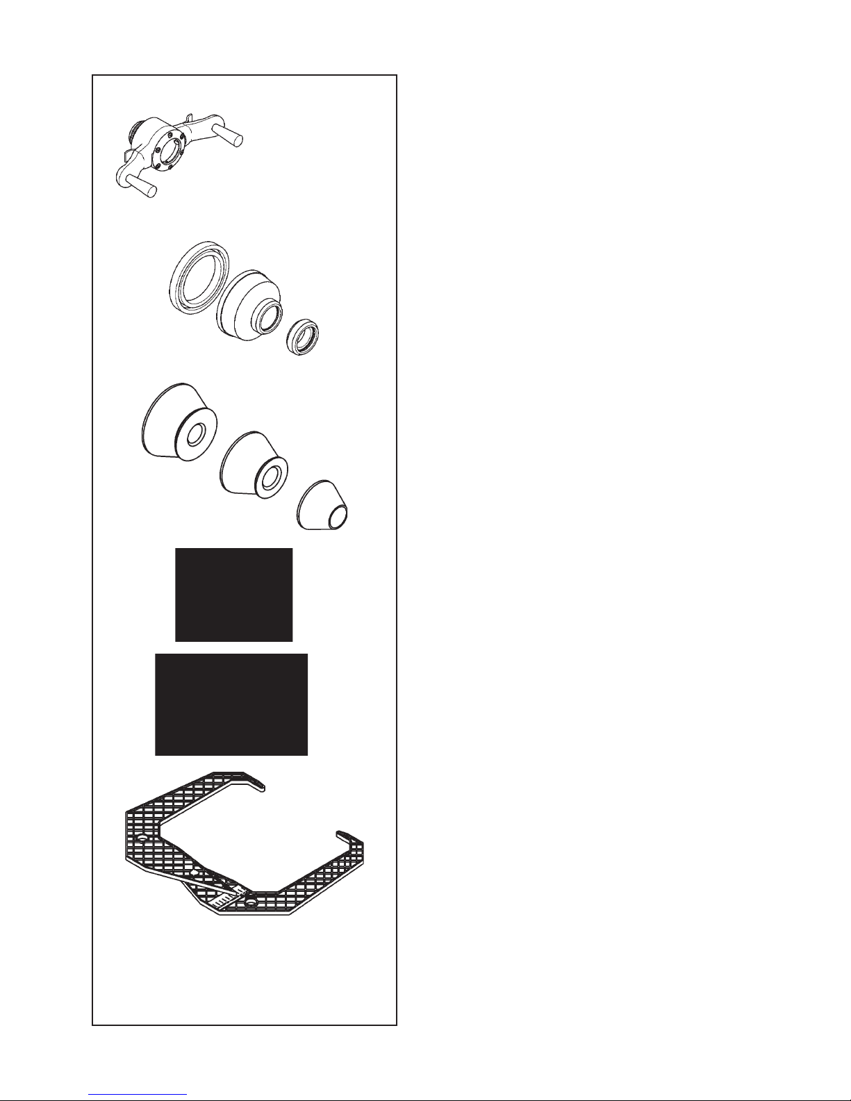
Accessories
3.1 Accessories
Refer to Figure 3.1-1.
The standard accessories are:
Quick-Release Hub Nut
Quick-clamping MZV (Ring-Nut)
Spacer ring
Universal drum
Universal drum cushion
Large cone
Medium cone
Small cone
User Calibration weight
W
eight pliers
Caliper
Page 13

13
EAA0263G66A
EAA0277G61A
EAC0058D08A
EAC0058D07A
EAC0058D15A
EAM0005D25A
EAM0005D24A
EAM0005D23A
EAM0005D40A
8-04250A
EAA0247G21A
EAA0263G66A
EAA0277G61A
EAC0058D08A
EAC0058D07A
EAC0058D15A
EAM0005D25A
EAM0005D24A
EAM0005D23A
EAM0005D40A
8-04250A
EAA0247G21A
Zubehör
3.1 Zubehör
Siehe Abbildung 3.1-1.
Das folgende Standardzubehör steht zur V
erfügung:
Schnellspannmutter
Quickmutter MZV
Distanzring
Drucktopf
Schützring für Drucktopf
Großer Konus
Mittlerer Konus
Kleiner Konus
Benutzerkalibriergewicht
Gewichtzange
Meßlehre
Accessoires
3.1 Accessoires
Se reporter à la Figure 3.1-1.
Les accessoires standard sont:
Manivelle de serrage rapide
Ecrou à serrage rapide MZV
Disque de distance
Coupelle plastique
Joint protection de la coupelle
Grand cône
Cône moyen
Petit cône
Masse de calibrage utilisateur
Pince à masses
Calibre largeur jantes
Page 14

14
1
2
3
4
6
7
8
1
2
9
5
4-1
4-2
OFF
ON
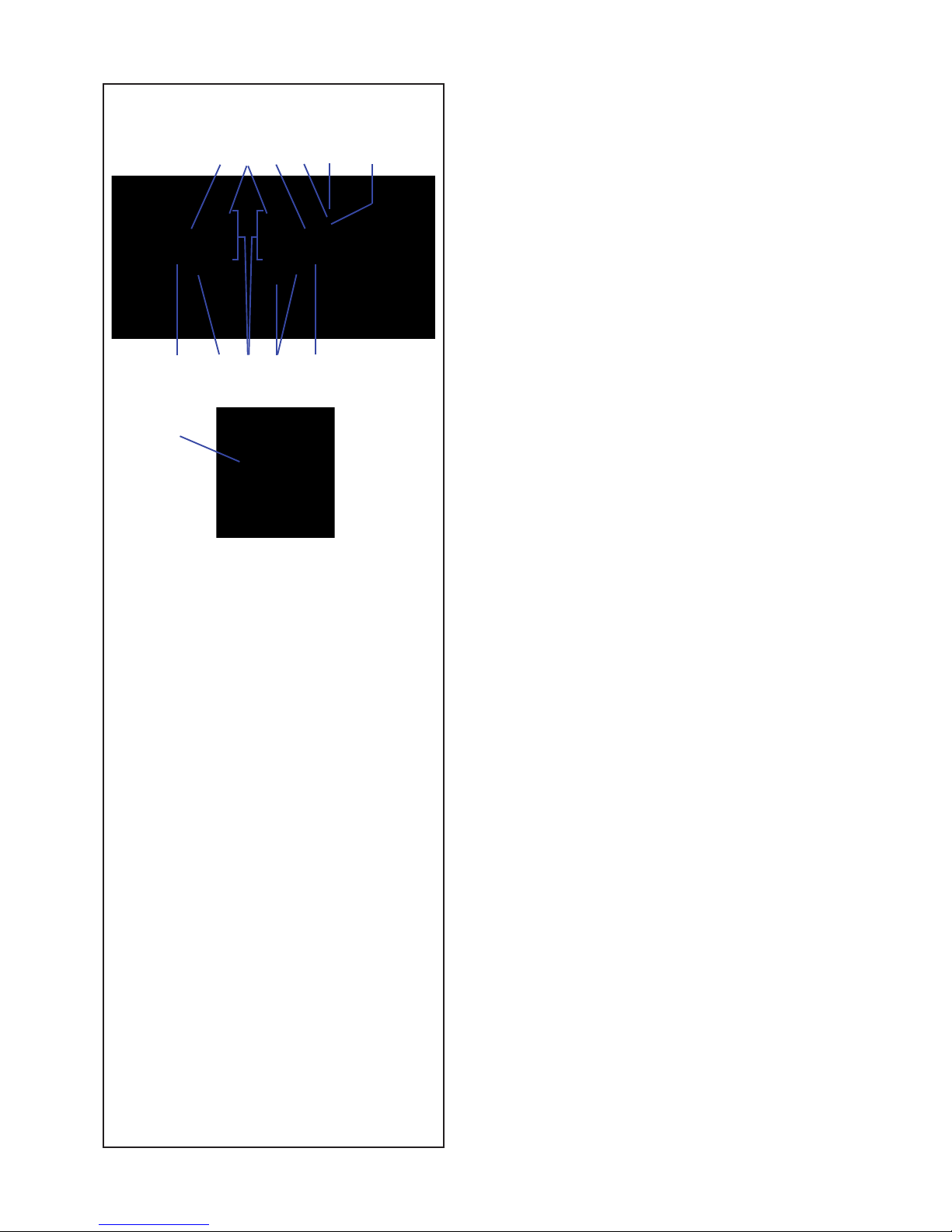
Layout
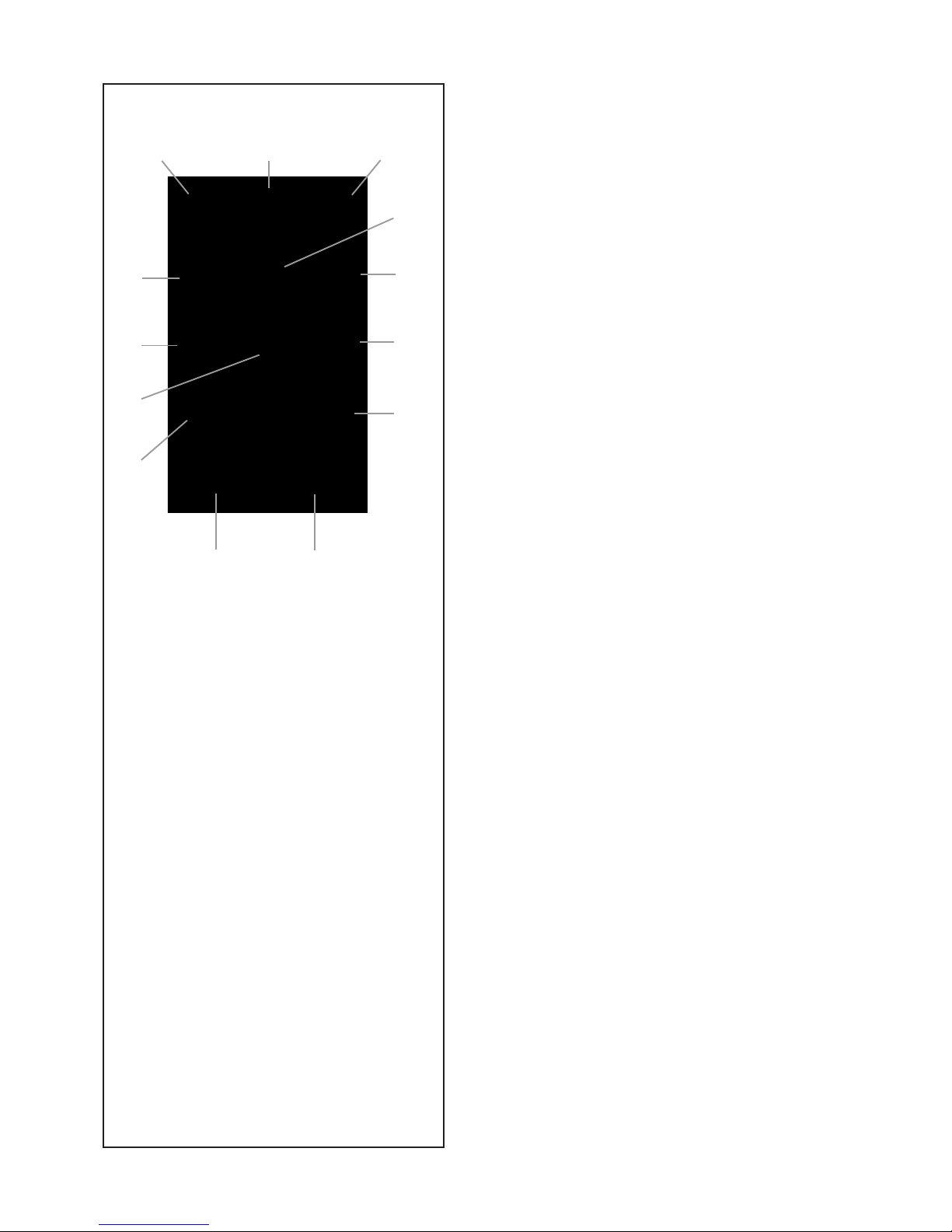
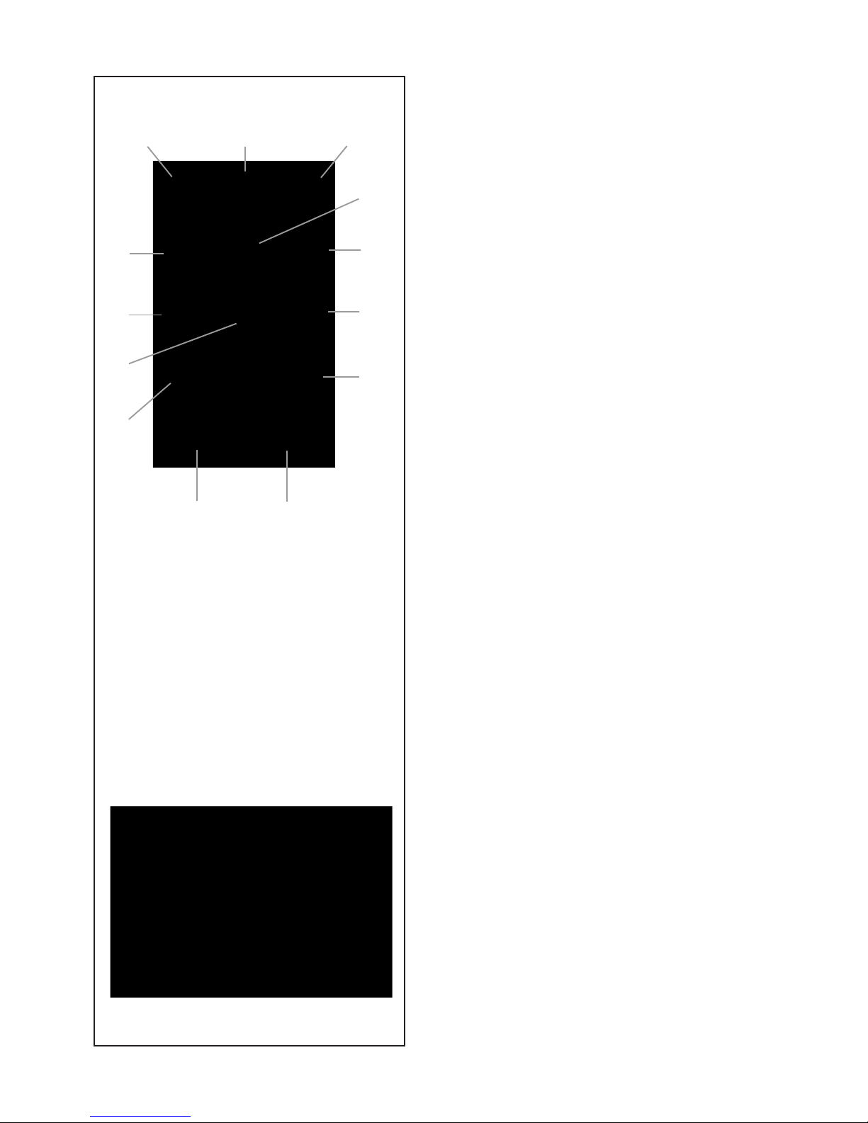
4.0 Layout
Refer to Figure 4-1.
Functional description of the unit:
1. Display
Refer to Chapter 4.1.
2. Input panel
Refer to Chapter 4.2.
3. Internal gauge arm
4. Flange
5. Stub shaft
6. Weight compartments
7. Storage areas for cones and hub nuts
8. Wheel guard
9. Brake Wheel
Refer to Figure 4-2.
1.
Mains switch (ON/OFF)
2. Power inlet
Page 15

15
Layout
4.0 Layout
Siehe Abbildung 4-1.
Funktionsbeschreibung des Geräts:
1. Display
Siehe Kapitel 4.1.
2. Eingabefeld
Siehe Kapitel 4.2.
3. Innerer Messarm
4.
Flansch
5. Flanschwelle
6. Gewichtefächer
7. Auf bewahrun gsbereiche für Konen oder
Spannteile
8. Radschutz
9. Bremsrad
Siehe Abbildung 4-2.
1.
Netzschalter (AN/AUS)
2. Netzanschluss
Disposition
4.0 Disposition
Se reporter à la Figure 4-1.
Description fonctionnelle de la machine :
1. Af! chage
Se reporter au Chapitre 4.1
2. Clavier
Se reporter au Chapitre 4.2
3. Jauge de déport interne
4. Montage
5. Embout d’arbre
6. Bac porte-plombs
7. Zones de stockage pour cônes et outils de
blocage
8. Carter de roue
9. Frein de roue
Se reporter à la Figure 4-2.
1.
Interrupteur secteur (ALLUMÉ / ÉTEINT)
2.
Branchement electrique
Page 16
16
4.1-1
Layout
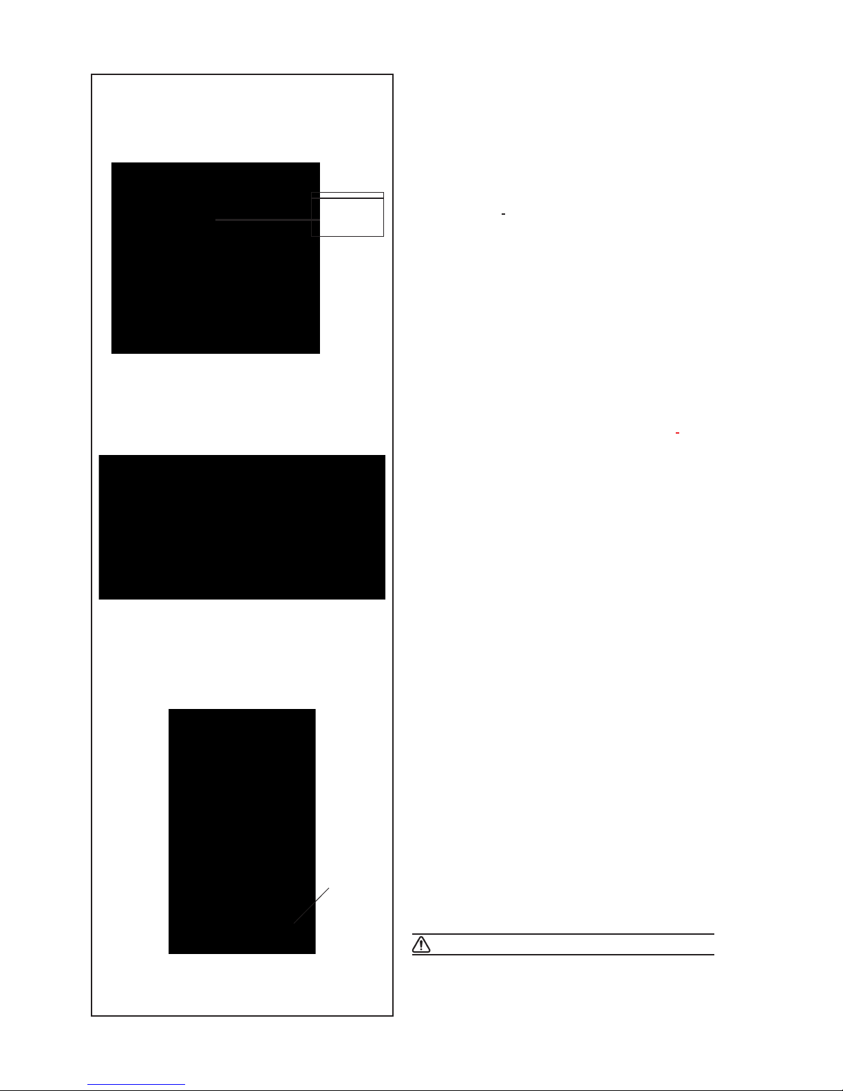
4.1 The display
Refer to Figures 4.1-1.
1. Rotation indicators of the correction plane.
The indicators show the direction the operator has
to rotate the wheel (by hand) after a balancing run.
2. Weight Application Position (WAP) indicator.
The indicator will light up when the wheel is in the
correct position for weight application. This indicator
will be referred to as the WAP indicator.
Refer to the weight mode selected before applying
a weight!
3. Display.
Depending on the stage of the program the display
gives the operator information about rim sizes,
balancing weights, error codes, etc.
4. Weight units indicator, “Oz”.
The
indicator will
light if the weight is displayed in
ounces instead of grams.
5. Motorcycle Dynamic and Static Indicator.
The indicator lights up when you activate the
motorcycle wheel balancing program or the single
weight (static mode).
6. Flange compensation.
This indicator lights up when fl ange compensation
is activated
7. Weight Position Indicator.
Apply a clip-on weight to the rim at the position
indicated when the WAP indicator for this plane
lights up.
8.
Weight Position Indicator.
Apply a stick-on weight to the rim at the position
indicated when the WAP indicator for this plane
lights up.
64 51
27 8 7
33
8
4
Page 17

17
Layout
4.1 Das Display
Siehe Abbildungen 4.1-1.
1. Rotationsanzeige der Korrekturebene.
Die
Anzeigen geben die Richtung an, in der
der Bediener das Rad (per Hand) nach einer
Auswuchtrotation drehen muss.
2. Gewichtanbringungspositionsanzeige (WAP).
Die Anzeige leuchtet ganz auf, wenn sich das
Rad in der richtigen Stellung zur Anbringung des
Gewichts befi ndet.
Diese Anzeige wird als WAP-Anzeige bezeichnet.
Achten Sie auf den gewählten Gewichtsmodus,
bevor Sie ein Gewicht anbringen!
3. Display.
Je nach Stand des jeweiligen Programms gibt
das Display dem Bediener Informationen über
Felgengröße, Auswuchtgewichte, Fehlercodes,
usw..
4. Gewichtseinheitsanzeige, “Oz”.
Diese Anzeige leuchtet auf, wenn das Gewicht in
Unzen anstatt in Gramm angegeben wird.
5. Anzeige Motorrad Dynamisch und Statisch
Die Anzeige leuchtet bei Aktivierung des Programms
zur Auswuchtung von Motorradrädern auf.
6. Kompensation des Flansches.
Di e se An z ei ge l euc hte t au f, w enn d ie
Kompensations des Flansches aktiviert wird.
7. Gewichtanbringungspositionsanzeige.
Befestigen Sie ein Klemm- oder ein Klebegewicht
an der angegebenen Felgenposition, wenn die
WAP-Anzeige dieser Ebene aufl euchtet.
8.
Gewichtanbringungspositionsanzeige.
Befe s tige n Sie e in Kl e bege w icht a n der
angegebenen Felgenposition, wenn die WAPAnzeige dieser Ebene aufl euchtet.
Disposition
4.1 L’af! chage
Se reporter à la Figure 4.1-1.
1.
Indicateurs de position de masses correctives
Les indicateurs indiquent la direction vers laquelle
l’opérateur doit tourner la roue (manuellement)
après un équilibrage.
2. Indicateur (WAP) Position de la Pose des
Masses
L’indicateur s’allume quand la roue est dans la
position correcte pour la pose des masses. Cet
indicateur est appelé indicateur WAP.
Se reporter au type de roue sélectionné avant de
poser la masse !
3. Af! chage
Lors des différentes étapes du programme
l’affi chage donne à l’opérateur des renseignements
sur la taille des jantes, les masses d’équilibrage,
les codes erreur, etc.
4. Indicateur “Oz” d’unités de poids
Cet indicateur s’allume si le poids est affi ché en
onces au lieu de grammes.
5. Indicateur Equilibrage roue mode dynamique
et statique moto.
L’indicateur s’allume à l’activation du programme
d’équilibrage des roues moto.
6. Compensation de la bride
Cet indicateur s’allume lors de la sélection du
compensation de la bride.
7. Indicateur de position des masses.
Poser une masse agrafée ou adhésive à la position
de jante indiquée quand l’indicateur Position masse
de ce plan s’allume.
8.
Indicateur de position des masses.
Poser une masse adhésive à la position de jante
indiquée quand l’indicateur “WAP” de ce plan
s’allume.
Page 18
18
13 9
5
1
3
2
11
6
10
12
8
4
7
4.2-1
Layout
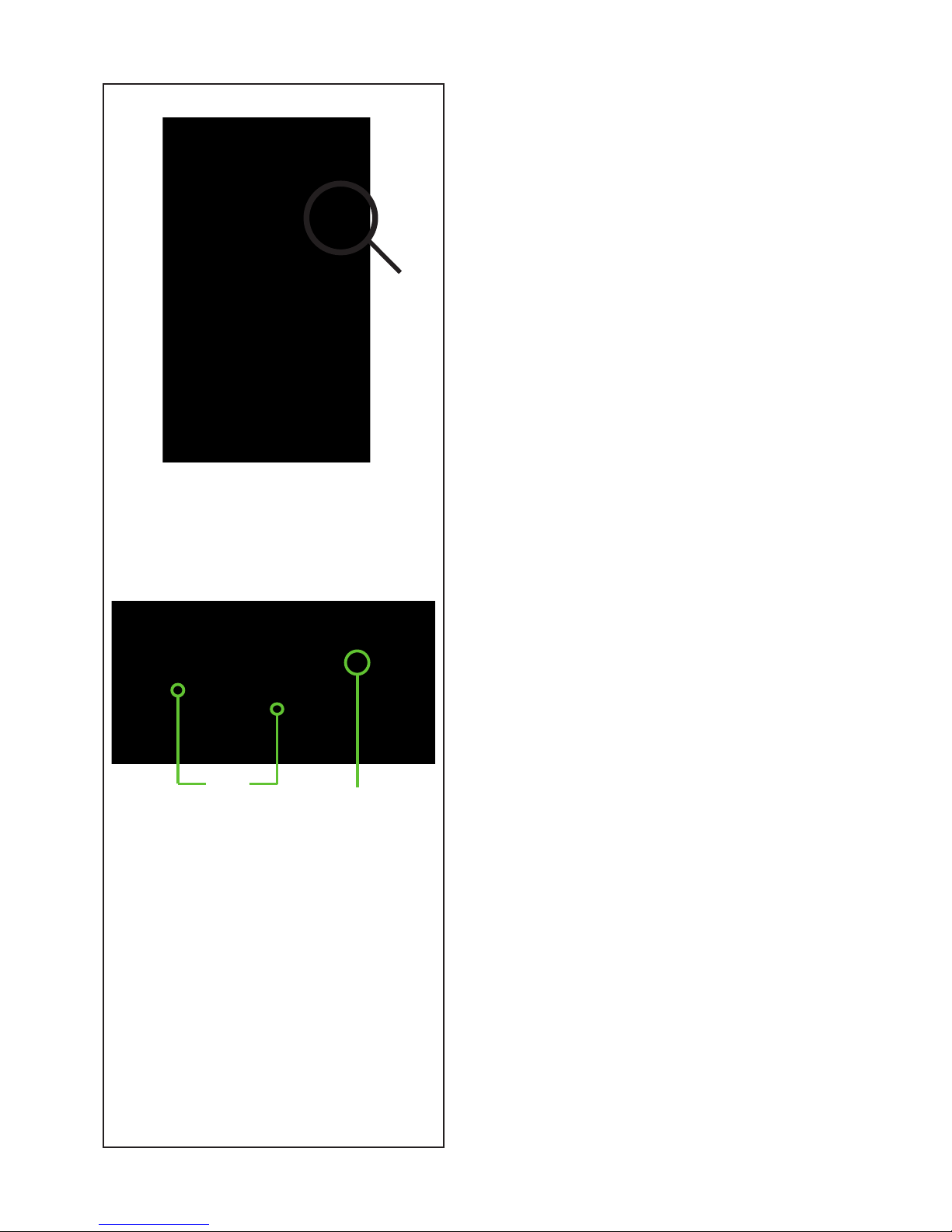
4.2 The input panel
Refer to Figure 4.2-1.
1. Diameter key with indicator.
Press to select “rim diameter” mode, the current
diameter or “dia” value will appear and the unit
will beep.
The current value will be shown on the display and
can be edited.
2. Width key with indicator.
Press to select “rim width” mode, the [¦- - -¦] symbol
will appear, representing the width value and the
unit will beep.
The current value will be shown on the display and
can be edited.
3. Offset key with indicator.
Press to select “Offset” mode, the ---I or current
offset value will appear and the unit will beep.
4. + key.
To increase an input value (e.g. rim diameter, offset,
rim width).
Hold the key down to increase the values shown
automatically.
5. - key.
To decrease an input value (e.g. rim diameter,
offset, rim width).
Hold down the key to reduce the values shown
automatically.
6. Function key.
Activates the second function of multi-function keys
(indicated by the graphics on the lower section of
the keys). Press this key and F appears on the
left display then disappears when you press one
of the function keys. The F on the display also
disappears when you press the function key again
(it is sometimes used like enter).
7. Fine key (Lens)
Press to toggle the read-out accuracy between
Normal, i.e. 25, 50 or 100 grams (0,5,1 or 2 oz)
depending on the registered value and Fine i.e. 10
grams (0.5oz) regardless of the registered value.
The unit will beep. Release the key to return to
normal accuracy. F+Fine key activates the car
wheel optimisation and minimisation operation.
The unit will beep.
Release the key to return to normal accuracy.
F+Fine key; activates the PRO MATCH function,
optimisation and minimisation procedure.
Page 19

19
Layout
4.2 Das Eingabefeld
Siehe Abbildung 4.2-1.
1. Durchmesser-Taste mit
Anzeige.
D r ü c k e n S ie d i e s e Ta s t e , u m d e n
„Felgendurchmesser”-Modus zu wählen. Es
erscheinen „dia”, der aktuelle Durchmesserwert,
und das Gerät piept.
Der aktuelle Werte wird auf dem Display dargestellt
und kann geändert werden.
2. Breiten-Taste mit Anzeige.
Drücken Sie diese Taste, um den „Felgenbreiten”Modus zu wählen. Das Symbol [¦- - -¦] und der
Breitenwert erscheinen und das Gerät piept.
Der aktuelle Werte wird auf dem Display dargestellt
und kann geändert werden.
3. Abstand-Taste mit Anzeige.
Drücken Sie diese Taste, um den Modus “Abstand”
(“Offset”) zu wählen. Es erscheinen die Anzeige
“- - -¦” und der aktuelle Abstandswert und das
Gerät piept.
4. + Taste
Zur E rhöhu ng de s Eing a bewer t es (z . B.
Felgendurchmesser, Abstand, Felgenbreite).
Halten Sie die Taste gedrückt, um den angezeigten
Wert automatisch zu erhöhen.
5. - Taste
Zur Verringerung des Eingabewertes (z. B.
Felgendurchmesser, Abstand, Felgenbreite).
Halten Sie die Taste gedrückt, um den angezeigten
Wert automatisch zu verringern.
6. Funktionstaste
Um die zweite Funktion der Multifunktionstasten
zu aktivieren (sie ist graphisch im unteren Teil
der Tasten dargestellt). Bei Drücken dieser
Taste erscheint “F” auf dem linken Display und
verschwindet wieder, wenn man danach eine der
Funktionstasten drückt. Das “F” verschwindet auch
vom Display, wenn man die Taste noch einmal
drückt (manchmal wird sie auch als “Enter”-Taste
verwendet).
7. Fein-Taste (Lupe)
Drücken Sie diese Taste, um zwischen der
Anzeigegenauigkeit Normal, d.h. 25, 50 oder 100
(0,5, 1 oder 2 Unzen) je nach gemessenem Wert,
und Fein, d.h. 10 Gramm (0,5 Unzen) unabhängig
vom erfassten Wert, hin und her zu schalten.
Wenn man „F” und danach die Feinanzeige-Taste drückt, wird die Funktion zum Optimieren und Minimieren von Pkw-Rädern aktiviert.
Disposition
4.2 Le Panneau de Données
Se reporter à la Figure 4.2-1.
1.
Touche diamètre avec indicateur
Appuyer sur cette touche pour sélectionner le mode
“diamètre de jante”. L’indicateur diamètre s’allume,
la machine émet un bip sonore.
La valeur en cours est indiquée sur l’écran, elle
peut être modifi ée.
2. Touche largeur avec indicateur
Appuyer sur cette touche pour sélectionner le mode
“largeur de jante”. L’indicateur
[¦- - -¦] s’allume, la
machine émet un bip sonore.
La
valeur en
cours est indiquée sur l’écran, elle
peut être modifi ée.
3. Touche déport avec indicateur.
Appuyer sur cette touche pour sélectionner le mode
“déport” (“Offset”). L’indicateur [- - -¦] s’allume, la
machine émet un bip sonore.
La valeur en cours est indiquée sur l’écran, elle
peut être modifi ée.
4. Touche +
Pour augmenter la valeur d’entrée (par ex. diamètre
de jante, déport, largeur de jante).
Maintenir appuyé pour changer automatiquement
la valeur indiquée.
5. Touche -
Pour diminuer la valeur d’entrée (par ex. diamètre
de jante, déport, largeur de jante).
Maintenir pour changer automatiquement la valeur
indiquée.
6. Touche Fonction
Presser cette touche pour activer la seconde
fonction
de touches
multi-fonction (graphiquement
visualisé dans la partie inférieure des touches
mêmes). L’’indication “F” sur l’affichage à la
gauche Il sera affi ché lorsque la touche “F” sera
sélectionné. L’indication “F” disparaîtra en pressant
de nouveau la touche, (parfois la touche est utilisée
aussi comme fonction de “ENTER”).
7. Touche ! ne (Loupe)
Appuyer sur cette touche pour basculer la précision
de lecture entre le Normal, c’est-à-dire 25, 50 ou
100 grammes (0,5, 1 o 2 oz), selon le valeur relevée
et 10 grammes (0,5 oz), indépendamment de la
valeur relevée. . La machine émet un bip sonore.
Relâcher la touche pour revenir à la précision
normale.
F+Fine ; active la fonction
“PRO MATCH”,
procédure de la optimisation et minimisation.
Page 20
20
4.2-1
4.2-2
13 9
5
1
3
2
11
6
10
12
8
4
7
Layout
8. Weight key
Press to select the required weight application
mode (weight mode), the unit will beep.
F
+Weight key; activates the Motorcycles wheel
balancing Mode.
9. Stop key.
Press to stop spinning the wheel.
The STOP key also has an emergency stop
function.
10. g/oz key.
Toggles between reading in grams and in ounces,
and vice versa.
F+g/oz; activates the C-Code functions, special
user functions.
11. Static/Dynamic key.
Toggles between dynamic and static modes.
F+Stat/Dyn; activates the function for balancing with
a stick-on counterweight inside the tyre.
The INT LED on the panel lights up.
12.
SWM key, hidden weight split and mm/inch Key
Press to select the SWM function, hidden weight
split.
This can
only be activated after selecting the
ALU2P/ALU3P application mode.
In combination with the “F” key, toggles between
readings in inches (default setting) and millimeters.
13. START key.
Starts the machine spinning the wheel.
4.3 Main shaft lock
Fig. 4.2-2 Pedal of main shaft lock
T
he
main shaft is locked when the pedal is depressed.
This facilitates tightening or untightening of the
clamping nut and retains the wheel in the correction
position for correct fi tting of the balance weights.
Note:
This lock is designed only to facilitate orientation
of the wheel and must not be used for braking the
main shaft.
Page 21

21
Layout
8. Gewicht-Taste.
Drücken Sie diese Taste, um den gewünschten
Gewichtsanbringungsmodus (Gewichtsmodus)
zu wählen. Das Gerät piept.
Wenn man „F” und danach die Gewicht-Taste
drückt, Moto wird die Funktion aktiviert.
9. Stopp-Taste.
Drücken Sie diese Taste, um die Rotation des
Rades zu sperren bzw. freizugeben.
Die STOP-Taste dient auch als Not-Aus-Schalter.
10. g/oz Taste
Mit dieser Taste ist es möglich, vom Ablesen in
Gramm zum Ablesen in Unzen umzuschalten. Wenn
man „F” und danach die g/oz-Taste drückt, werden
die C-Code Funktionen aktiviert (siehe Kapitel 5.7);
es handelt sich um spezielle Benutzerfunktionen.
11.Taste Statisch/Dynamisch
Mit dieser Taste ist es möglich, die Einstellung
vom dynamischen auf den statischen Modus
umzuschalten und umgekehrt. Wenn man F und
danach die Taste Stat/Dyn drückt, aktiviert man
die Funktion für das Auswuchten mit Klebegewicht
innen im Reifen.
Auf dem Eingabefeld geht die LED “INT” an.
12.SWM-Taste und mm/inch.
Drücken Sie diese Taste zur Aufteilung des
versteckten Gewichts SWM aktiviert. Diese
Funktion kann nur aktiviert werden, wenn der
Anbringungsmodus ALU 2P/ALU 3P gewählt wurde.
Zusammen mit der Taste „F” ändert es bei
jedem Drücken die Ableseeinstellung von Zoll
(Grundkonfi guration) auf Millimeter und umgekehrt.
13. START Taste
Startet die Maschine für den Messlauf.
4.3 Feststellbremse
Bild 4.2-2 Pedal der Feststellbremse
Bei
getretenem Pedal wird die Hauptwelle festgestellt.
Hierdurch wird das Anziehen bzw. Lösen der
Radspannmutter erleichtert. Außerdem kann zum
Anbringen der Ausgleichsgewichte das Rad in der
eingedrehten Ausgleichsposition gehalten werden.
Hinweis:
Diese Feststellbremse ist nur eine Positionierhilfe
und darf nicht zum Abbremsen der Hauptwelle
benutzt werden.
Disposition
8. Touche de Masse
Appuyez pour sélectionner le mode de pose des
masses requis (mode de poids), l’unité émet un
bip sonore.
F+Touche de Masse ; active la fonction Moto.
9. Touche stop
Presser cette touche pour bloquer la rotation libre
de la roue. Le frein on débloquera en pressant
encore la touche.
La touche STOP sert aussi d’interrupteur d’arrêt
d’urgence.
10. Touche g/oz
A
vec
cette touche il est possible de commuer entre
lecture en grammes et lecture en onces.
Presser en premier F et puis la Touche g/oz pour
activer la fonction C-Code (voir chapitre 5.7),
fonctions spéciales pour l’utilisateur.
11. Touche Statique/Dynamique
Avec cette touche il est possible de commuer la
position entre modalité dynamique et modalité
statique. Presser en premier F et puis la Touche
Stat/Dyn, la fonction pour l’équilibrage avec masses
adhésif à l’intérieur du pneu est activée.
Sur l’Affi chage le Led “INT” s’illumine.
12. Touche SWM, en permettant la division de
masse et mm/pouce.
Appuyez pour sélectionner la fonction SWM, en
permettant la division de masse en deux parties.
Cette fonction est seul possible si la manière
d’application ALU 2P / ALU 3P a été sélectionné
avant. La lecture en pouce (confi guration de base)
ou en millimètre varie en alternance à chaque
pression par le biais de la touche “ F “.
13. Tasto START
Appuyer sur cette touche pour Initialiser la lancée
de mesure.
4.3 Blocage de l’arbre principal
Fig. 4.2-2 Pédale de blocage
L
’ar
bre principal est bloqué quand la pédale est
actionnée. Cela permet de serrer ou de desserrer
l’écrou de serrage plus facilement et de maintenir la
roue en position de correction pour une mise en place
correcte des masses d’équilibrage.
Remarque:
Ce système de blocage n’est qu’une aide de
positionnement et ne doit pas être utilisé pour
arrêter la course du mandrin.
Page 22

22
5.1-4
5.1-5
Operation
5.0 Operation
This chapter describes how to operate the unit in order
to balance a wheel.
The standard balancing runs will be described fi rst.
In chapter 5.4 and up special modes and functions
will be described.
Be sure to be familiar with:
- possible dangers, refer to chapter 1
- the unit, refer to chapter 4.
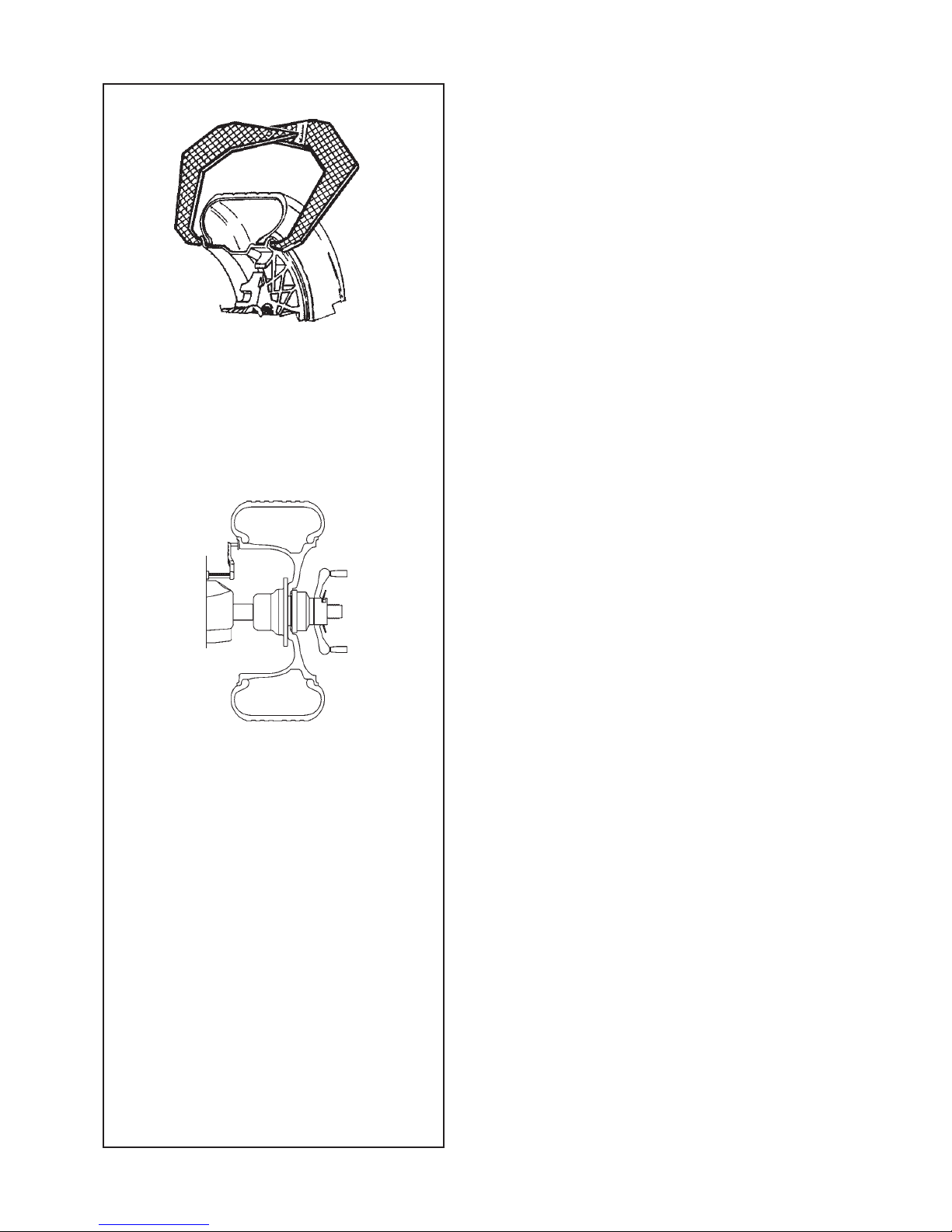
5.1 Clamping a car wheel
Fig. 5.1-4 illustrates clamping a conventional car w
he
el
using a clamping adaptor on the central bore.
Fig. 5.1-5 illustrates clamping a stud hole located
car wheel or a car wheel without centre bore using a
universal clamping adaptor.
The range and applications of the clamping means are
described in separate leafl ets.
Fig. 5.1-4 Clamping adaptor to clamp centre bore
located car wheels
1 Cone for car wheels
2 Rim
3 Clamping head with clamping nut (quick–clamping
nut)
4 Wing nut for clamping
Fig. 5.1-5 Universal clamping adaptor for clamping stud
hole located wheels or wheels with closed
rim. This clamping adaptor is also capable of
clamping centre bore located wheels when
suitable centring rings are used.
1 Rim
2 Quick–clamping nut
3 Centring ring for centre bore located car wheels
(optional extra).
Page 23

23
Betrieb
5.0 Betrieb
In diesem Kapitel wird beschrieben, wie mit dem Gerät
ein Rad ausgewuchtet wird.
Zue
rst werden die standardmäßigen Auswuchtvorgänge
beschrieben. In den Kapiteln ab 5.4 werden spezielle
Auswuchtungen und Funktionen beschrieben.
Stellen Sie sicher, dass Sie mit folgendem vertraut
sind:
- Den möglichen Gefahren, siehe Kapitel 1.
- Dem Gerät , siehe Kapitel 4.
5.1. Aufspannen eines Pkw–
Rades
Au f d em B ild 5 .1- 4 wi rd d a s A ufs pa n ne n
ein e
s h erkö m mli c hen PKW- Rads mi t ei n er
Mittenzentriervorrichtung gezeigt.
Bild 5.1-5 zeigt das Aufspannen eines bolzenzentrierten
Pkw-Rades bzw. eines Pkw-Rades ohne Mittenloch mit
einer Universalspannvorrichtung.
Die Auswahl und Verwendung der Spannmittel sind in
speziellen, eigenen Broschüren beschrieben.
Bild 5.1-4: Mittenzentriervorrichtung für das Aufspannen
von mittenzentrierten PKW-Rädern.
1 Pkw-Aufnahmekonus
2 Felge
3 Drucktopf mit Spannmutter (Schnellspannmutter)
4
Flügelmutter zum Spannen
Bild 5.1-5: Universalspannvorrichtung für das
Aufspannen von PKW-Rädern mit geschlossener
Felge, die mit Bolzen zentriert sind.
Sie kann zusammen mit entsprechenden Zentrierringen
auch zum Aufspannen von mittenzentrierten PKWRädern verwendet werden.
1 Felge
2 Schnellspannmutter
3 Zentrierring für mittenzentrierte PKW-Räder
(Zubehör).
Utilisation
5.0 Utilisation
Ce chapitre décrit l’utilisation de la machine pour
équilibrer une roue.
Les
étapes d’équilibrage standard sont décrites en
premier. Au chapitre 5.4 et au-delà vous trouverez la
description des modes et fonctions spéciaux.
Veuillez-vous familiariser avec :
- les dangers possibles, se reporter au chapitre 1
- la machine, se reporter au chapitre 4.
5.1 Serrage d’une roue de voiture
t
our
isme
La Fig. 5.1-4 montre le serrage d’une roue de voiture
tourisme courante à l’aide d’un cône de serrage.
La Fig. 5.1-5 montre le serrage d’une roue de voiture
tourisme à centrage par boulons ou d’une roue de
voiture sans trou central à l’aide d’un dispositif de
serrage universel.
La sél e ct ion et l’ u tilisat i on des mo y ens de
serrage sont décrites dans des manuels séparés.
Fig. 5.1-4 Cône de serrage pour les roues de voitures
tourisme centrées par le trou central
1 Cône pour roues de voitures tourisme
2 Jante
3 Tête de serrage avec écrou de serrage (écrou à
serrage rapide)
4 Ecrou à oreilles pour serrage
Fig. 5.1-5 Moyen de serrage universel pour les roues
à jante fermée ou les roues centrées par
des boulons. Ce moyen se prête également
pour les roues centrées par trou central
si les anneaux de centrage appropriés
(accessoires) sont utilisés.
1 Jante
2 Ecrou à serrage rapide
3 Anneau de centrage pour roues de voitures
tourisme à centrage central (option).
Page 24
24
5.2.1-1
5.2.1-2
5.2.2-1
1
I
O
Operation
5.2 Preparation
• The operator should be familiar with the warnings
and cautions.
• The operator should be qualifi ed to work with the
unit.
• Always ensure that the wheel guard (when
applicable) is lifted and the gauge arm is in its home
position (far left position) when the unit has been
switched off.
5.2.1 Power up
• Do not keep any key pressed down during power
up
.
Refer to Figure 5.2.1-1.
• Insert the power cable plug in the mains socket.
• Set the switch on the socket to the “I” position.
Note:
If the unit beeps and does not proceed or if
an error code is shown, refer to Chapter 7.
The unit will beep and perform a self-test now.
The display and the weight position indicators relating
to the current weight mode will stay on (default).
Refer to Figure 5.2.1-2 for an example.
The unit is now ready to receive input.
5.2.2 Emergency stop
Refer to Figure 5.2.2-1.
To perform an emergency stop:
• Se
lect the STOP key to apply the electronic
brake.
In the event of an emergency stop due to an unexpected
action by the unit, rethink the steps that were made:
Did the operator make an error or omit to do
something?
Correct the input and continue working. No special
procedure is required.
Did the unit do something unexpected?
• Read the relevant chapters again.
• Prepare the unit for a restart:
switch off the unit
switch on the unit again.
• Carefully repeat the commands with the manual
available.
• If the unit does not function correctly, call the service
team immediately and:
PREVENT ANY FURTHER USE OF THE UNIT.
Page 25

25
Betrieb
5.2 Vorbereitung
• Der Bediener muss mit den Warnhinweisen und
Vorsichtsmaßnahmen vertraut sein.
• Der Bediener muss für die Arbeit mit dem Gerät
qualifi ziert sein.
• Stellen Sie immer sicher, dass die Radabdeckung
ange h oben i s t und d e r Mess a rm in d er
Ausgangsstellung (ganz links) ist, wenn die
Maschine ausgeschaltet ist.
5.2.1 Anschalten
• Halten
Sie beim Einschalten keine Taste gedrückt!
Siehe Abbildung 5.2.1-1.
• Stecken Sie den Stecker des Netzkabels in die
Stromversorgungsdose.
• Sc
halten Sie den Schalter, der sich in der Nähe des
Steckers befi ndet, auf “I”.
Hinweis: Schauen Sie in Kapitel 7 nach, wenn das
Gerät piept oder stecken bleibt oder wenn
ein Fehlercode angezeigt wird.
Das Gerät piept und führt einen Selbsttest durch.
Daraufhin werden die Displays und die Anzeigen
für die Gewichtspositionen je nach dem aktuellen
Gewichtsmodus (Default) angezeigt.
Abbildung 5.2.1-2 zeigt ein Beispiel.
Das Gerät ist nun bereit zur Eingabe.
5.2.2 Notabschaltung
Siehe Abbildung 5.2.2-1.
So führen Sie eine Notabschaltung durch:
• B e tätige n Sie d i e STOP- Taste , um di e
elektronische Bremse zu aktivieren.
Wenn
Sie auf Grund eines unerwarteten Verhaltens
des Geräts eine Notabschaltung durchgeführt haben,
versuchen Sie sich an die Schritte zu erinnern, die Sie
davor vorgenommen haben:
Hat der Bediener einen Fehler gemacht oder etwas
vergessen?
Korrigieren Sie den Fehler und fahren Sie mit
d
er Arbeit fort. Es müssen keine besonderen
Maßnahmen durchgeführt werden.
Hat das Gerät irgend etwas Unerwartetes getan?
•
Lesen Sie die entsprechenden Kapitel noch einmal durch.
• Bereiten Sie das Gerät auf einen Neustart vor.
Schalten Sie das Gerät ab.
Schalten Sie das Gerät wieder ein.
• Wiederholen Sie vorsichtig die Befehle und
befolgen Sie dabei die Anweisungen in der
Betriebsanleitung.
• Rufen Sie sofort den Kundendienst an, wenn das
Gerät nicht richtig funktioniert.
V E RHI N DE R N S I E E I N E W EI T ERE
BENUTZUNG DES GERÄTS.
Utilisation
5.2 Préparation
• L’op é rateur d oit se f a miliar i ser ave c les
avertissements et les mesures de sécurité.
• L’opérateur doit être formé pour travailler avec la
machine.
• S’assurer toujours que la protection de la roue
(quand elle peut être appliquée) est soulevée et que
le bras de mesure est en position de repos (placé
à l’extrême gauche) quand l’unité est éteinte.
5.2.1 Allumage
• Ne pas toucher la machine pendant l’allumage!
Se reporter à la Figure 5.2.1-1.
• G
reffer l’épine du câble d’alimentation dans la prise
de réseau.
• Activer l’interrupteur qui se trouve en proximité de
l’épine en le portant en position «I».
Remarque : Si la machine émet un bip sonore et
s’arrête ou si un code erreur est indiqué,
se reporter au Chapitre 7.
La machine émet ensuite un bip sonore et effectue
une vérifi cation.
Seront donc affi chés l’indicateur d’allumage, l’affi cheur
et les indicateurs des positions des masses en rapport
au type courant de roue (préétabli d’usine).
Se reporter à la Figure 5.2.1-2 pour avoir un exemple.
La machine est maintenant prête pour l’entrée des
paramètres.
5.2.2 Arrêt d’urgence
Se reporter à la Figure 5.2.2-1.
Pour ef
fectuer un arrêt d’urgence :
• Ap
puyer sur la touche STOP pour actionner le frein
électronique.
Après un arrêt d’urgence causé par une action
imprévue de la machine, réfl échissez aux étapes
effectuées :
Est-ce une erreur de l’opérateur ?
Corriger l’entrée et continuer. Il n’y a pas de
procédure spéciale à suivre.
Est-ce une action imprévue de la machine ?
• Relire les chapitres appropriés encore.
• Préparer la machine pour un redémarrage :
Éteindre la machine
attendre quelques secondes
rallumer la machine.
• Répéter soigneusement les instructions avec le
manuel à portée de main.
• Appeler le SAV immédiatement si le mauvais
fonctionnement se répète et :
INTERDISEZ TOUTE UTILISATION DE LA MACHINE
.
Page 26

26
5.2.2-1
4
10
Operation
5.2.3 Shutting down
Always shut down properly when work is complete:
• Remove the wheel from the balancer.
• Re
move the cones and hub nut from the stub shaft.
Check the surfaces (internal and external) of the
cones for damage. The condition of the cone is
very important for a good balance quality.
• Check the thread of the hub nut and stub shaft.
• Clean all threads and surfaces with a dry, soft cloth.
• Store the cones and the hub nut in the correct place.
• Unplug the mains cable from the power outlet.
• Check the power cable for damage or wear.
• Tidy up the storage areas.
• Clean the display and input panel with a soft, dry
cloth.
• Remove old wheel weights and other material from
under the balancer. The balancer must rest on its
three feet only.
5.2.4 Settings
After switching on the unit, a default weight mode is
shown.
If the
unit then shows another weight mode,
refer to Chapter 5.3.2.
The unit of measurement indicated at power up is
inches, but the setting selected before switching off
for grams / ounces remains.
5.2.4.1 Changing the Weight Unit
Default weight unit setting:
grams.
Proceed as follows
to change the weight unit, whether
you have already spun the wheel or not.
Refer to Figure 5.2.1-1.
• Press the key “g/oz” (10).
When oz is applied, the indicator (4) is bright
• Repeat the procedure to return to the previous unit
displayed.
5.2.4.2 Changing the Dimensions Unit
Default diameter and width unit setting: inches.
• Press and hold down the “F” key and then press
“-mm-inch”.
Repeat the procedure to return to the previous unit
displayed.
Page 27

27
Betrieb
5.2.3 Abschalten
Schalten Sie das Gerät am Ende einer Arbeitsschicht
immer ordnungsgemäß ab:
• Nehmen Sie das Rad von dem Auswuchtgerät.
• Neh
men Sie die Konusse und die Spannmutter
von der Flanschwel l e. Über p rüfen Sie die
Oberfl ächen der Konusse (innen und außen) auf
Beschädigungen. Die Unversehrtheit des Konus ist
sehr wichtig für eine gute Auswuchtqualität.
• Überprüfen Sie das Gewinde der Schnellspannmutter
und der Flanschwelle.
• Reinigen Sie alle Gewinde mit einem trockenen und
weichen Lappen.
• Be w a hr en S i e d i e K o n us se u n d d i e
Schnellspannmutter an dem ordnungsgemäßen
Platz auf.
• Ziehen Sie das Stromversorgungskabel aus der
Steckdose.
• Überprüfen Sie das Stromversorgungskabel auf
Beschädigungen und Verschleiß.
• Räumen Sie die Aufbewahrungsbereiche auf.
• Reinigen Sie das Display und das Eingabefeld mit
einem trockenen und weichen Lappen.
•
Entfernen Sie alte Radgewichte und anderes Material
aus dem Bereich unter dem Auswuchtgerät. Das
Auswuchtgerät darf nur auf seinen drei Füßen stehen.
5.2.4 Einstellungen
Nach dem Eins c h al te n d e s Ge r ä ts wi r d ei n
standardmäßiger Gewichtsmodus angezeigt. Sehen
Sie in Kapitel 5.3.2 nach, wenn das Gerät einen
anderen Gewichtsmodus anzeigt.
Die standardmäßige Maßeinheit beim Einschalten des
Geräts ist Zoll; es bleibt aber die Einstellung in Gramm
oder Unzen, die vor dem Abschalten vorgenommen wurde.
5.2.4.1 Umschaltung der Gewichtseinheit
Standardeinstellung der Gewichte: Gramm.
Mit dieser Methode können Sie die Maßeinheit
des Gewichts ändern – sowohl vor oder nach dem
Messlauf.
Siehe Abbildung 5.2.2-1.
• Drücken Sie die “g/oz”
Taste (10).
Wenn oz angewendet wird, ist die LED (4) hell.
• Wiederholen Sie den Vorgang, um die Anzeige
wieder auf vorherigen zu schalten.
5.2.4.2 Umschaltung Größeneinheit
Standardeinstellung der Einheit für Durchmesser und
Breite: Zoll
• Halten Sie die Taste “F” gedrückt und
drücken Sie die “-mm/inch” Taste.
Wiederholen Sie den Vorgang, um die Anzeige wieder
auf vorherigen zu schalten.
Utilisation
5.2.3 Arrêt
À la fi n du travail compléter toujours les opérations de
façon convenable:
• Retirer la roue de l’équilibreuse.
• R
eti
rer les cônes et la manivelle de serrage. Vérifi er
que les surfaces des cônes (internes et externes)
ne sont pas endommagées. Le cône est très
important pour un équilibrage de bonne qualité.
• Vérifi er le taraudage de la bague de blocage et de
l’embout d’arbre.
• Nettoyer tous les fi lets et surfaces avec un chiffon
doux et sec.
• Replacer les cônes et la bague à leur juste
emplacement.
• Débrancher la fi che d’alimentation électrique de la
prise de courant.
• Vérifi er que le câble secteur n’est pas endommagé
ou usé.
• Ranger les bacs porte-plombs.
• Nettoyez le panneau d’affi chage et d’entrée avec
un chiffon sec.
• Retirez les vieux masses de roue et autres matériaux
qui se trouvent sous la machine. L’équilibreuse doit
reposer sur ses trois pieds seulement.
5.2.4 Réglages
Après l’allumage de l’unité un type de roue est affi ché
par défaut. Si l’unité
montre ensuite un type de roue
différent, reportez-vous au Chapitre 5.3.2.
Les paramètres par défaut de la machine sont les
grammes et les pouces. Pour les changer, reportezvous au Chapitre 5.2.4.1 et 5.2.4.2 respectivement.
5.2.4.1 Commutation Unité de Poids
Sélection poids de défaut en :
grammes.
Sélectionner cette méthode pour changer l’unité de
poids, indifféremment avant ou après avoir exécuté
un lancement.
Se reporter à la Figure 5.2.2-1.
• Presser la touche “g/oz” (10).
Quando “oz” é aplicado, o indicador (4) é luminosos.
• Répétez la procédure pour revenir à l’écran
précédent.
5.2.4.2 Commutation Unités dimensionnelles
de défaut diamètre et largeur en : pouces.
• Maintenu pressé la touche “F” et presser la
touche “- mm-inch.”
Répéter la procédure pour reconvertir la
visualisation précédent.
Page 28
28
5.3-1
5.3-2
1
12
LED
Operation
5.3 Balancing procedure
The unit always has a weight mode automatically
selected, refer to the display. Select the appropriate
key (1 - Fig.5.3-1) to scroll through the weight modes
continuously. The weight mode currently selected is
shown by the illuminated indicator(s).
NORMAL
Used for steel rims.
ALU mode
Used for light alloy rims or where one or more stickon weights are to be used.
The stick-on weight(s) must be applied by hand.
Hidden Weight Mode
Used for light alloy rims or for wheels that are
diffi cult to balance.
The stick-on weight(s) must be applied with the
gauge arm. This guarantees more accurate weight
positioning compared to applying the stick-on
weight(s) by hand.
Note: If the stick-on weight must be hidden
behind two spokes, select the Split Weight
Mode before applying the weight in the
right plane. Refer to Chapter 5.4.1.
STATIC
Retrieve the function with key 12 fi g. 5.3-2. Two
LEDs light up and fl ash.
Used for small wheels that are not balanced
dynamically, e.g.: small moped wheels.
No “left” or “right” weight is calculated.
Mount the wheel according to Chapter 5.1 and select
the correct weight mode.
Page 29

29
Betrieb
5.3 Auswuchtvorgang
Das Ger ät z eig t im mer aut omat isch ei nen
Gewi
chtsmodus an. Blättern Sie mit der entsprechenden
Taste (1 - Bild 5.3-1) durch die verschiedenen
Gewichtsmodi. Der ausgewählte Gewichtsmodus wird
durch den entsprechenden Leuchtanzeiger angezeigt.
NORMAL
Wird für Stahlfelgen benutzt.
“ALU-Modes”
Wird für Leichtmetallfelgen oder in Situationen
benutzt, bei denen ein oder mehrere Klebegewichte
benutzt werden sollen. Die Klebegewichte werden
mit der Hand angebracht
“Hidden Weight Modes” (HWM)
Wird bei Leichtmetallfelgen und bei Rädern, die
schwer auszuwuchten sind, benutzt.
Die Klebegewichte werden mit dem Messarm
angebracht. Dies gewährleistet eine genauere
Positionierung des Klebegewichts im Vergleich zur
Anbringung mit der Hand.
Hinweis: Wenn ein Klebegewicht hinter zwei
Speichen versteckt werden muss,
müssen Sie “Split Weight Mode” wählen,
bevor Sie das Gewicht in der rechten
Ebene anbringen. Siehe Kapitel 5.4.1.
“STATIC”
Diese Funktion wird mit der Taste 12 Abb. 5.3-2
abgerufen; es leuchten 2 LEDs auf und blinken.
Wird bei kleinen Rädern benutzt, die nicht
dynamisch ausgewuchtet werden, z. B. kleine
Motorradräder.
Es wird kein „linkes” oder „rechtes” Gewicht
berechnet.
Montieren Sie das Rad nach der Anleitung im Kapitel
5.1 und wählen Sie den richtigen Gewichtsmodus.
Utilisation
5.3 Procédure d’équilibrage
La machine a toujours un type de mode d’équilibrage
sélectionné à l’affi chage.
Sélectionnez la touche appropriée (1 - Fig.5.3-1) pour
faire dérouler les différents modes d’équilibrage. Le
mode sélectionné est indiqué par le(s) leed(s) allumées
correspondant à la position des masses.
NORMAL
Utilisé pour les jantes en acier.
Modes ALU
Utilisés pour les jantes en métal léger ou lorsqu’une
utilisation d’un ou plusieurs masses adhésifs est
nécessaire.
Le(s) masses adhésif(s) doit/doivent être posé(s)
manuellement.
Modes de Masses Cachés
Utilisés pour les jantes en métal léger, ou pour les
roues diffi ciles à équilibrer.
Le(s) masses adhésif(s) doit/doivent être placé(s)
avec le bras de jauge qui assure un placement
des masses plus précis en comparaison avec le
placement manuel.
Remarque : Si la masses adhésive du plan
droit doit être caché derrière les batons,
sélectionner le Mode Masses Divisé
avant de placer le masses dans le plan
droit. Se reporter au Chapitre 5.4.1.
STATIQUE
Cette fonction est rappelée avec la touche 12
illustré dans l’illustration 5.3-2; à l’activation deux
LED intermittents s’illuminent. Utilisé pour les roues
de moins de 3‘’ qui ne sont pas dynamiquement
équilibrées, par ex. les roues de moto de petite
cylindrée. Placer une masse seulement sur la
ligne médiane de la roue. Les masses «gauche»
et «droite» ne sont pas calculés.
Installer la roue selon le Chapitre 5.1 et sélectionner
le type de roue correct.
Page 30
30
5.3.1-1
5.3.1-2
Operation
5.3.1 Rim data input
Dimensions can be measured by hand and then typed
in on the keyboard.
Dimension
Units
diameter: inches (default) or mm.
rim width:
inches (default) or mm.
offset: millimetres.
To change the units, refer to Chapter 5.2.4.2.
MANUAL data entry
Manual data entry is required only if the gauge arm
malfunctions. In that case proceed as follows:
- Rim or tyre diameter
• Read the nominal rim diameter directly on the rim
or tyre itself.
• Select the diameter key on the control panel. The
last value entered appears.
• Enter the value read previously using the appropriate
keys (refer to Chapter 4.2).
• Select another measurement to edit (if necessary)
or spin the wheel.
- Rim width
• Measure the rim manually with the callipers (refer
to Fig. 5.3.1-1) or read the measurement directly
on the rim itself if it’s written there.
• Press the “Rim width” key.
• Enter the value manually using the keyboard.
- Offset:
• Position the gauge arm correctly as described
above in the “Rim Diameter” phase of the Automatic
Data Entry operation
• Read the arm extraction value on the gauged
column.
• Enter the value read previously using the appropriate
keys.
Page 31

31
Betrieb
5.3.1 Eingabe der Felgendaten
Die Maße können manuell gemessen werden und über
die Tastatur eingegeben werden.
Maße Einheiten
Durchmesser:
Zoll (Standard) oder mm.
Felgenbreite: Zoll (Standard) oder mm.
Offset (Abstand): Millimeter.
Anweisungen zum Ändern der Einheiten fi nden Sie in
Kapitel 5.2.4.2.
MANUELLE Dateneingabe.
Eine manuelle Dateneingabe ist nur erforderlich,
wenn der Messarm versagt oder Schwierigkeiten
beim Gebrauch auftreten. Gehen Sie in diesem Fall
folgendermaßen vor:
- Felgen- oder Reifendurchmesser
• An der Felge oder am Reifen den Nenndurchmesser
der Felge ablesen.
• Wählen Sie die Taste des Durchmessers auf dem
Eingabefeld. Der zuletzt eingegebene Wert wird
angezeigt.
• Den zuvor abgelesenen Wert eingeben; dazu die
entsprechenden Tasten verwenden (siehe Kapitel
4.2).
• Wählen Sie ein anderes Maß, das geändert werden
soll, oder führen Sie den Messlauf aus.
- Felgenbreite
• Messen Sie manuell mit Hilfe der Schieblehre
(siehe Abbildung 5.3.1-1), oder lesen Sie das
Maß direkt von der Felge ab, falls angegeben.
• Die Taste “Felgenbreite” drücken.
• Von Hand den gemessenen Wert über die
Tastatur eingeben.
- Offset
• D e n M e s s a r m k o r r e k t w i e u n t e r
“Felgendurchmesser” bei der automatischen
Datenerfassung positionieren.
• A n d er Sk a la au f d e m M ess arm de n
entsprechenden Wert ablesen.
• D en zuvor a bgele s enen Wer t mit de n
entsprechenden Tasten eingeben.
Utilisation
5.3.1 Entrée Paramètres Roue
Les dimensions peuvent être mesuré manuellement
et vous insérez par clavier
.
Dimension Unités
diamètre: Pouce (défaut) ou mm.
largeur de jante: Pouce (défaut) ou mm.
déport: millimètres.
Pour changer les unités, se reporter au Chapitre
5.2.4.2.
Entrée MANUELLE des données.
L’entrée manuelle des données est requise
uniquement si la jauge de déport ne fonctionne
pas. Dans ce cas:
- Diametre de la jante ou de la roue
• Obtenir les diametre de la jante en lisant directement
sur la jante ou sur le pneu.
• À partir du tableau de commande sélectionner la
touche de les diamètre. La dernière valeur introduite
est affi chée.
• Modifi er la valeur en sélectionnant les touches
appropriées (se reporter au Chapitre 4.2).
• Sélectionner une autre dimension (si nécessaire)
à modifi er ou effectuer un lancement.
- Largeur de jante
• Mesurez manuellement avec le compas (voir
Figure5.3.1-1) ou dérivez de la jante, si reporté.
• Sélectionner le touche “Largeur de la jante”.
• Entrez manuellement.
- Offset:
• Positionner correctement les jauge sur la
jante, voir “Entrée de données par JAUGE DE
DÉPORT”.
• Lire la valeur d’écart de l’échelle.
• Insérer le valeur en sélectionnant la touche
approprié.
Page 32

32
5.3.2.1-1
5.3.2.2-1
5.3.2.2-3
5.3.2.2-4
5.3.2.2-6
5.3.2.2-5
5.3.2.2-2
5.3.2.1-2
Operation
5.3.2 Balancing
This chapter describes how to balance a wheel.
For help on:
rim data input
refer to Chapter 5.3.1
spinning the wheel refer to Chapter 5.3.3
weight application refer to Chapter 5.3.4
the check spin refer to Chapter 5.3.5
5.3.2.1 Normal weight mode
When selected, the display is as shown in Figure 5.3.2.1-
1.
Figure 5.3.2.1-2 shows the rim reference point.
• Establish the following dimensions:
- Rim diameter of the reference point.
- Rim width.
- Of
fset of the reference point.
• After entering the dimensions, spin the wheel.
• Apply the clip-on weights at the indicated positions,
at the 12 o’clock position.
• Perform a check spin when done.
5.3.2.2 ALU weight modes
Select an ALU weight mode if one or more stick-on
weights will be used.
When selected, the display shows:
ALU1: Refer to Figure 5.3.2.2-1.
ALU2: Refer to Figure 5.3.2.2-2.
ALU3: Refer to Figure 5.3.2.2-3.
ALU4: Refer to Figure 5.3.2.2-4.
ALU5: Refer to Figure 5.3.2.2-5.
• Establish the following dimensions:
- Rim diameter of the reference point.
- Rim width.
- Offset of the reference point.
Note: For ALU2 and ALU3 the right hand plane
is equal to the front surface of the fl ange.
The weight should be applied in that
plane. Deviations in that plane should be
compensated by increasing or reducing
the weight applied. Refer to Figure 5.3.2.2-
6.
• After entering the dimensions
, spin the wheel.
• A
pp
ly the clip-on/stick-on weights at the indicated
12 o’clock positions.
• Perform a check spin when done.
Page 33

33
Betrieb
5.3.2 Auswuchten
In diesem Kapitel wird das Auswuchten eines Rades
beschrieben.
Hier fi nden Sie Hilfe zu den folgenden
Themen:
Eingabe von Felgendaten Kapitel 5.3.1
Durchführen des Messlaufs Kapitel 5.3.3
Anbringen von Gewichten Kapitel 5.3.4
Der Kontrolllauf Kapitel 5.3.5
5.3.2.1 Normaler Gewichtsmodus
Wird dieser Typ gewählt, so sieht das Display aus wie
A
bbildung 5.3.2.1-1. Die Abbildung 5.3.2.1-2 zeigt den
Felgenreferenzpunkt.
• Geben Sie die folgenden Maße an:
- Felgendurchmesser des Referenzpunkts.
- Felgenbreite.
- Offset des Referenzpunkts.
• Nachdem die Maße eingegeben sind, starten Sie
den Messlauf.
• Br i n ge n S i e d i e Kl e mm ge wi c ht e a n de n
angegebenen Stellen (in 12-Uhr-Position) an.
• Führen Sie danach einen Kontrolllauf durch.
5.3.2.2 „ALU”-Gewichtsmodi
Wenn ein oder mehrere Klebegewichte benutzt werden
s
ol
len, müssen Sie den “ALU”-Gewichtmodus wählen.
Das Display sieht dann folgendermaßen aus:
ALU1: Siehe Abbildung 5.3.2.2-1
ALU2: Siehe Abbildung 5.3.2.2-2
ALU3: Siehe Abbildung 5.3.2.2-3
ALU4: Siehe Abbildung 5.3.2.2-4
ALU5: Siehe Abbildung 5.3.2.2-5.
• Geben Sie die folgenden Maße ein:
- Felgendurchmesser des Referenzpunkts
- Felgenbreite
- Offset des Referenzpunkts
Hinweis: Bei ALU2 und ALU3 entspricht die rechte
Ebene der Vorderseite des Flansches. Das
Gewicht muss in dieser Ebene angebracht
werden. Abweichungen von dieser Ebene
müssen ausgeglichen werden, indem das
Gewicht erhöht oder verringert wird. Siehe
Abbildung 5.3.2.2-6.
• Nachdem die Maße eingegeben sind, starten Sie
den Messlauf.
• Befestigen Sie die Klemm-/Klebegewichte an den
angegebenen Stellen in der 12-Uhr-Position.
• Führen Sie danach einen Kontrolllauf durch
.
Utilisation
5.3.2 Equilibrer un type de roue
Ce chapitre décrit comment équilibrer une roue.
Pour des renseignements sur:
Entrée données jante
voir Chapitre 5.3.1
Faire tourner la roue voir Chapitre 5.3.3
Application des masses
voir Chapitre 5.3.4
Lancement de contrôle voir Chapitre 5.3.5
5.3.2.1 Type de roue normal
A la sélection, l’affi chage égale Figure 5.3.2.1-1.
La Figure 5.3.2.1-2 indique le point de référence sur
la jante.
• Indiquez les dimensions suivantes:
- Diamètre de jante au point de référence.
- Largeur de jante.
- Offset du point de référence.
• Une fois les dimensions entrées, faites tourner la
roue.
• Appliquez les masses à clip aux positions
indiquées, à 12 heures.
• Faites un lancement de contrôle à la fi n.
5.3.2.2 Types de roues ALU
Si un ou plusieurs masses adhésifs vont être utilisés,
sélectionnez un type de roue
ALU.
A la sélection, l’affi
chage égale:
ALU1: Voir Figure 5.3.2.2-1.
ALU2: Voir Figure 5.3.2.2-2.
ALU3: Voir Figure 5.3.2.2-3.
ALU4: Voir Figure 5.3.2.2-4.
ALU5: Voir Figure 5.3.2.2-5.
• Indiquez les dimensions suivantes:
- Diamètre de j
ante du point de référence.
- Largeur de jante.
- Offset du point de référence.
Note: Pour ALU2 et ALU3 le plan droit est égal à
la surface frontale de la bride. Le poids doit
être appliqué dans ce plan. Les déviations
de ce plan doivent être compensées en
augmentant ou diminuant les masses
appliqué. Voir Figure 5.3.2.2-6.
• Une fois les dimensions entrées, faites tourner la
roue.
• Appliquez les poids à clip/adhésifs aux positions
indiquées , à 12 heures.
• Faites un lancement de contrôle à la fi n.
Page 34

34
5.3.2.3-1
5.3.2.3-2
5.3.2.3-3(1)
5.3.2.3-3(2)
5.3.2.4-1
5.3.2.4-2
Operation
5.3.2.3 Alu2 and Alu3 (HWM) mode
Select this mode for more exact balancing, weight
positioning behind spokes or special rims (PAX, TRX,
CTS, etc.).
When selected, the display shows:
HWM1: Refer to Figure 5.3.2.3-1.
Two stick-on weights.
HWM2: Refer to Figure 5.3.2.3-2.
Left plane: clip-on weight
Right plane: stick-on weight.
Note:
The relevant HWM indicator is lit.
Figure 5.3.2.3-3 (1) and (2) shows the rim reference
points.
The distance between the left plane and right plane
offset points must be 77 mm (3”) minimum.
Note: To balance a PAX wheel (HWM1 only):
• Select mm mode (Chapter 5.2.4.2
).
• The rim diameter can only be changed to the
predefi ned values. Enter dimensions.
• After entering the dimensions, spin the wheel.
Always apply the stick-on weights at the positions
indicated. Check the correct weight application
distance when the display shows the value “0“ and
the machine beeps.
• Apply the weight in the left plane.
Note: If the weight is to be split and put exactly
behind two spokes, select SWM now.
Refer to Chapter 5.12.
• Apply the weight in the right plane.
• Perform a check spin.
5.3.2.4 Static balancing
Only static imbalance is measured and corrected.
Whe
n selected, the display is as shown in Figure 5.3.2.4-
1.
Figure 5.3.2.4-2 shows the recommended rim
reference point.
• Establish the following dimensions:
- Rim diameter of the reference point.
- Width. If the rim width is ≤ 3”, enter 3”.
- Offset of the reference point.
• After entering the dimensions, spin the wheel.
• Apply the stick-on or clip-on weight at the 12
o’clock position.
• Perform a check spin when done.
Page 35

35
Betrieb
5.3.2.3 Modus “ALU 2” und “ALU 3” (HWM)
Wählen Sie diesen Modus, um eine exaktere
Aus
wuchtung zu erzielen, um das Gewicht hinter
Speichen zu verstecken oder bei Spezialfelgen (PAX,
TRX, CTS, etc).
Das Display sieht dann folgendermaßen aus:
HWM1: Siehe Abbildung 5.3.2.3-1.
Zwei Klebegewichte
HWM2: Siehe Abbildung 5.3.2.3-2.
Linke Ebene: Klemmgewicht
Rechte Ebene: Klebegewicht
Hinweis: Die entsprechende HWM-Anzeige ist
erleuchtet.
Di e Abbildung 5.3.2.3-3 (1) und (2) zeigt die
Felgenreferenzpunkte.
Der Abstand zwischen dem Offsetpunkt der linken
Ebene und dem Offsetpunkt der rechten Ebene muss
mindestens 77 mm (3 Zoll) betragen.
Hinweis: Auswuchtung eines PAX-Rades (nur
HWM1):
• Wählen Sie den mm-Modus (Kapitel 5.2.4.2).
• Als Felgendurchmesser können nur vorgegebene
Werte ausgewählt werden. Geben Sie die Maße
ein.
• Nachdem die Maße eingegeben sind, starten Sie
den Messlauf.
Be nutzen Sie um die Klebegewi chte an den
angegebenen Stellen zu befestigen.
• Bringen Sie das Gewicht in der linken Ebene an.
Hinweis: Wählen Sie jetzt SWM, wenn das Gewicht
geteilt und genau hinter zwei Speichen
versteckt werden soll: Siehe Kapitel 5.12.
• Bringen Sie das Gewicht in der rechten Ebene an.
• Führen Sie danach einen Kontrolllauf durch.
5.3.2.4 Statische Auswuchtung
Hier wird nur die statische Unwucht gemessen und
korrigiert.
Das Display sieht dann aus wie
Abbildung 5.3.2.4-1.
Di
e Abbildung 5.3.2.4-2 zeigt den empfohlenen
Felgenreferenzpunkt.
• Geben Sie die folgenden Maße ein:
- Felgendurchmesser des Referenzpunkts.
- Breite der Felge. Wenn die Felgenbreite
≤ 3”
beträgt, geben Sie “3” ein.
- Offset des Referenzpunkts.
• Nachdem die Maße eingegeben sind, starten Sie
den Messlauf.
• Befestigen Sie das Klebe- oder Klemmgewicht an
der angegebenen Stellen in der 12-Uhr-Position.
• Führen Sie danach einen Kontrolllauf durch.
Utilisation
5.3.2.3 Mode des masses Caché
Sélectionner cette fonction pour un équilibrage plus
correct ; pour
la pose des masses derrière les rayons,
ou pour les jantes spéciales (PAX, TRX, CTS, ecc.).
Quand ce mode est sélectionné, l’affi cheur apparaît
comme indiqué :
HWM1- à la fi gure 5.3.2.3-1.
Deux masses adhésifs.
HWM2- à la fi gure 5.3.2.3-2.
Plan gauche: masses à clip
Plan droit: masses adhésif.
Remarque:
Le voyant HWM approprié est allumé.
La Figure 5.3.2.3-3 (1) et (2) indique les points de
référence de la jante.
La distance entre le point de déport du plan gauche et
du plan droit doit être minimum 77 mm (3”).
Remarque: Pe r équilibrer une roue PAX
(uniquement HWM1):
• Sélectionner le mode mm (Chapitre 5.2.4.2).
• Le diamètre de la jante peut être changé seulement
aux valeurs prédéfi nies. Entrez des dimensions.
• Effectuer un lancement de la roue.
Appliquer toujours les masses adhésifs aux positions
indiquées.
• Appliquer les masses sur le plan de gauche.
Remarque: Si les masses doit être divisé et
placé exactement derrière deux rayons,
suivre les indications du Chapitre 5.12.
• Appliquer les masses sur le plan de droite.
• À la fi n, effectuer un tour de contrôle.
5.3.2.4 Type de roue statique
Dans ce cas le déport et la correction intéressent
uniquement le balourd statique.
Quand
le mode
est sélectionné, l’affi cheur apparaît
comme indiqué à la Figure 5.3.2.4-1.
La Figure 5.3.2.4-2 montre le point de référence sur
la jante.
• Indiquez les dimensions suivantes:
- Diamètre de la jante du point de référence.
- Largeur. Si la largeur de la jante est ≤ 3”,entrez
3”.
- Offset du point de référence.
• Effectuer un lancement de la roue.
• Appliquer la masse auto-adhésive à la position à
12 heures.
• À la fi n, effectuer un tour de contrôle.
Page 36

36
5.3.3-1
5.3.4-3
5.3.4-2
5.3.4-4
5.3.4-1
1
Operation
5.3.3 Spinning the Wheel
The wheel data must be acquired and the type of rim
to be used must be entered.
With Code C13 set on “1”;
• Close the wheel guard.
With Code C13 set on “0”;
• Close the wheel guard and press ST
ART.
The motor starts up and the wheel spins.
Wheels must turn towards the right, seen from the side
of the unit on which they are mounted.
The measurement is completed as soon as the
direction indicators light up. The unit beeps. The brake
will be applied automatically and the wheel will stop.
The weight(s) to be applied will be shown on the
display. For higher precision, select Fine (1, Figure
5.3.3-1).
• Lift the wheel guard to its vertical position.
5.3.4 Weight application
The following weight types and application methods
are available:
- clip-on weights.
Always apply by hand.
- stick-on weights.
Must be applied by hand.
Note
: Hand applied weights must always be
applied exactly perpendicular to the shaft
(12 o’clock position).
After spinning the wheel look at the rotation indicators
for the left plane of the wheel (1-Figure 5.3.4-1):
• Slowly rotate the wheel manually (e.g. counter
clockwise) until the three top LEDs are on (1-Figure
5.3.4-2).
• Continue with the rotation until all the LEDs switch
off progressively towards the centre.
Once the correct weight application position is reached,
only the green central LED is on Figure 5.3.4-3.
Note: At the correct angular position all rotation
indicators will be lit. If the wheel has been
rotated too far, only the indicators for the
other half will be lit. Refer to Figure 5.3.4-
4. The wheel has to be gently reversed.
2
1
Page 37

37
Betrieb
5.3.3 Der Messlauf
Die Raddaten müssen erfasst sein, danach geht man
folgendermaßen vor:
Wenn der Code C13 auf „1” gestellt ist:
• Schließen Sie den Radschutz.
Wenn der Code C13 auf „0” gestellt ist:
•
Schließen Sie den Radschutz und drücken Sie
START.
Der Motor startet und das Rad dreht sich.
Bei Betrachtung von der Aufspannseite des Geräts aus
muss das Rad nach rechts gedreht werden.
Die Messung ist beendet, sobald die Richtungsanzeigen
aufleuchten. Das Gerät lässt dann einen Piepton
ertönen und die Bremse wird automatisch aktiviert.
Das Rad hält.
Das Gewicht / die Gewichte, das/die angebracht
werden muss/müssen, werden auf dem Display
angezeigt. Wählen Sie “Fein” (1-Abbildung 5.3.3-1),
um eine höhere Genauigkeit zu erreichen.
• Heben Sie den Radschutz an, bis er vertikal steht.
5.3.4 Anbringen von Gewichten
Es stehen die folgenden Arten von Gewichten und
Anbringungsmethoden zur V
erfügung:
- Klemmgewichte.
Diese werden immer mit der Hand angebracht.
-
Klebegewichte.
Diese werden je nach Gewichtsmodus mit der Hand
angebracht.
Hinweis: Gewichte, die mit der Hand angebracht
werden, müssen immer genau senkrecht
über der Welle angebracht werden (in
12-Uhr-Position).
Achten Sie nach dem Messlauf auf die Rotationsanzeigen
für die linke Ebene des Rads (siehe 1 - Abbildung
5.3.4-1):
• Drehen Sie das Rad langsam mit der Hand (z.B.
geg
en den Uhrzeigersinn), bis die drei oberen LED
leuchten (siehe 1 – Abbildung 5.3.4-2).
• Drehen Sie weiter, bis alle LED nach und nach zur
Mitte hin ausgehen.
Wenn die korrekte Position zum Anbringen des
Gewichts erreicht ist, leuchtet nur die mittlere, grüne
LED (siehe Abbildung 5.3.4-3).
Hinweis: Wenn das Rad zu weit gedreht wurde,
le
uchten nur die Anzeigen auf der
anderen Hälfte auf. Siehe Abbildung
5.3.4-4. Das Rad muss dann etwas
zurückgedreht werden.
Utilisation
5.3.3 Lancement roue
Les paramètres de la roue et du type de jante utilisée
doivent avoir été préalablement saisis.
A
vec le Code C13 paramétré “1”;
• Fermer le carter de roue.
Avec le Code C13 paramétré “0”;
• Fermer le carter de roue et presser ST
ART.
Le moteur démarre et la roue commence à tourner.
Les roues doivent tourner vers la droite en ayant comme
point d’observation le côté du montage de la roue.
La mesure est terminée lorsque les indicateurs de
direction s’allument. L’unité émettra un bip sonore. Le
frein entrera en fonction automatiquement et la roue
s’arrêtera.
La/les masses à poser est/sont indiquée(s) sur
l’affichage. Pour un affichage au gramme près,
Appuyer sur la touche Fine (1, Figure 5.3.3-1).
• Soulever le carter de roue, en le portant en position
verticale.
5.3.4 Pose des masses
Les types de masses et méthodes de pose suivantes
sont disponibles:
-
masses agrafées:
Poser toujours manuellement.
- masses adhésives:
Appliquer manuellement.
Remarque: L e s m a s se s a pp li ca b l e s
manuellement doivent toujours être posées
de façon exactement perpendiculaire à
l’axe (position à 12 heures).
Après avoir lancé la roue, observer les indicateurs de
rotation pour le plan gauche de la roue (1-Figure 5.3.4-1):
• Tourner lentement la roue à la main (Ex. : dans
le sens antihoraire) jusqu’à ce que les trois LEDs
supérieures s’allument (1-Figure 5.3.4-2).
• Poursuivre la rotation jusqu’à ce que toutes les
LEDs s’éteignent progressivement vers le milieu.
Quand on atteint la position correcte de la masse à
appliquer, seule la LED verte centrale reste allumée
(Figure 5.3.4-3).
Remarque : À la position angulaire correcte tous
les indicateurs de rotation seront allumés.
Si la roue se trouve au-delà du point
préétabli, seuls les indicateurs de l’autre
moitié s’allumeront. Se reporter à la
Figure 5.3.4-4. Il faudra donc tourner en
sens inverse délicatement.
Page 38

38
5.3.4-5
5.3.4-6
Operation
The weight to be applied in that plane is shown on
the display.
• Turn the wheel manually until it reaches the
counterweight application point
Attaching a clip-on weight.
Refer to Figure 5.3.4-5.
• Clip-on weights must always be applied in the 12
o’clock position.
• The lip should rest on the rim edge. Use the weight
pliers to position it.
In STATIC mode only the left hand display is used.
Attaching a stick-on weight.
ALU or STATIC weight modes only:
Refer to Figure 5.3.4-6.
• Apply the weight on the rim in the 12 o’clock
position.
Page 39

39
Betrieb
Das Gewicht, das in der Ebene angebracht werden
muss, wird auf dem Display angegeben.
• Drehen Sie das Rad mit der Hand, um es in die
Stel
lung zur Anbringung der Gegengewichte zu
bringen.
Anbringen eines Klemmgewichts.
Siehe Abbildung 5.3.4-5.
• Klemmgewichte müssen immer in der 12-Uhr-
Position angebracht werden.
• Die Lippe muss über die Felgenkante geschoben
werden. Schlagen Sie das Gewicht mit der
Gewichtzange leicht in Position.
Im “STATIC”-Modus wird nur das linke Display benutzt.
Anbringen eines Klebegewichts
Nur bei „ALU” oder „STATIC” Gewichtsmodi:
Siehe Abbildung 5.3.4-6.
• Bringen Sie das Gewicht in der 12-Uhr-Position.
Utilisation
L
a v
aleur de la masse à appliquer sur ce plan est
montrée sur l’affi cheur.
• Tourner la roue manuellement tant que la position
d’application des contrepoids est atteint.
Pose des masses à clip.
Se reporter à la Figure 5.3.4-5.
• Les masses à clip doivent toujours être appliquées
de façon perpendiculaire, position à 12 heures.
• Le clip devrait poser sur le bord de la jante. Utiliser
la Pinces à masses pour le placer correctement.
Dans le mode STATIQUE seul l’affi cheur de gauche
doit être utilisé.
Pose des masses adhésives.
Uniquement dans les modes ALU ou STATIQUE:
Se reporter à la Figure 5.3.4-6.
• Appliquer les masses sur la jante à la position à 12
heures.
Page 40

40
5.3.5-1
Operation
5.3.5 Check spin
It is good practice to perform a check spin after appl
ying
the weights.
• Spin the wheel.
If the wheel has been balanced properly, “000” will
be displayed for both planes. To check how much
imbalance is left:
• Select the fi ne key - Fig. 5.3.5-1.
• Rotate the wheel by hand.
The weight to be applied is shown on the display.
Note: The operator should decide if applying the
stated weight is necessary.
5.3.6 Results recalculation
After spinning a wheel it is possible to enter new rim
data
or select
another weight mode. The results are
recalculated automatically, if possible.
Selecting another weight mode:
- Between NORMAL, ALU and STATIC: no additional
steps required.
• Select “fine” Figure 5.3.5-1 (Lens) to toggle
between Weight Application Mode and Data Entry
Mode.
• State the new plane reference points.
• Apply the weight(s).
To have a recalculation done:
• Select the required weight mode. Check and/or edit
rim or plane data when necessary.
• Rotate the wheel to the left plane WAP position and
apply the weight.
• Rotate the wheel to the right plane WAP position
and apply the weight.
• Perform a check spin.
1
Page 41

41
Betrieb
5.3.5 Kontrolllauf
Es ist ratsam, nach Anbringen der Gewichte zur
Bestätigung einen Kontrolllauf durchzuführen.
• Führen Sie danach einen Kontrolllauf durch.
W
enn das Rad
richtig ausgewuchtet wurde, erscheint
für beide Ebenen „000” auf dem Display. So überprüfen
Sie, wie groß die verbliebene Unwucht ist:
• Betätigen Sie die “Fein”-Taste (1) Abb. 5.3.5-1.
• Drehen Sie das Rad mit der Hand.
Das anzubringende Gewicht wird auf dem Display
angezeigt.
Hinweis: Der Bediener muss entscheiden, ob es
notwendig ist, das angegebene Gewicht anzubringen.
5.3.6 Neuberechnung der Ergebnisse
Nach Rotation des Rades ist es möglich, neue
Felg
endaten einzugeben oder einen anderen
Gewichtsmodus zu wählen. Die Ergebnisse werden
automatisch neu berechnet, wenn dies möglich ist.
Änderung von Felgendaten:
- Nicht-HWM: Automatische Neuberrechnung
• Betätigen Sie die „Fein” Taste(Lupe 1, Abbildung 5.3.5-
1), um zwischen dem Gewichtsanbringungsmodus
und dem Dateneingabemodus hin und her zu
schalten.
• Geben Sie die neuen Referenzpunkte der Ebenen
an.
• Bringen Sie das Gewicht oder die Gewichte an.
Zur Durchführung einer Neuberechnung:
• Wählen Sie den gewünschten Gewichtsmodus.
Überprüfen und, falls notwenig, ändern Sie die
Daten für die Felge oder die Ebene.
• Drehen Sie das Rad in die Gewichtsanbrin-gung-
sposition der linken Ebene und bringen Sie das
Gewicht an.
• Drehen Sie das Rad in die Gewichtsanbrin-gung-
sposition der rechten Ebene und bringen Sie das
Gewicht an.
• Führen Sie einen Kontrolllauf durch.
Utilisation
5.3.5 Tour de roue de contrôle
Il est conseillé d’effectuer un lancement de contrôle
après avoir appliqué les masses.
• Effectuer le lancement de la roue.
Si
la roue a été correctement équilibrée l’affi chage pour
les deux plans sera “000”. Pour vérifi er un éventuel
déport résiduel:
• Sélectionner la touche Fine - Fig. 5.3.5-1.
• Faire tourner la roue manuellement.
L’affi cheur indiquera les masses à appliquer.
Remarque : L’opérateur évaluera l’opportunité
d’appliquer la masse affi chée.
5.3.6 Recalcul des résultats
Après avoir effectué un tour de roue vous pouvez
entrer
de nouveaux paramètres
roue ou sélectionner
un autre type de jante. Les résultats, si possible, seront
recalculés automatiquement.
Sélection d’un autre mode d’équilibrage:
- Entre NORMAL, ALU et STATIQUE : aucune autre
phase additionnelle n’est requise.
• Sélectionner la touche “Fine” (Loupe 1, Figure
5.3.5-1) pour basculer entre le mode de pose des
masses et le mode d’entrée des paramètres.
• Indiquer les nouveaux points de référence de plan.
• Appliquer la masse ou les masses.
Pour recalculer:
• Sélectionner le type de roue désiré. Si nécessaire
vérifi er et/ou modifi er les paramètres de la jante ou
du plan d’application.
• Faites tourner la roue jusqu’à l’allumage de
l’indicateur WAP du plan gauche et placer la masse.
• Faites tourner la roue jusqu’à l’allumage de
l’indicateur WAP du plan droit et placer la masse.
• Effectuer un lancement de contrôle.
Page 42

42
5.4.1-1
5.4.1-2
Operation
5.4 Special modes
Selecting the F key enables
the operator to scroll the
following modes in sequence:
- Split Weight Mode (SWM),
- Minimisation mode.
5.4.1 Split Weight Mode
Selecting is possible only after balancing a HWM whe
el
that has an imbalance
≥ 10 grams in the right plane.
Note: The “fine” read-out accuracy is not
available with this mode.
Select this mode to “hide” the right plane weights split
into two parts behind the two spokes that are nearest
to the calculated weight application position. That way,
the weights are not visible from “outside”.
Take into account the following limitations (refer to
Figure 5.4.1-1):
- The whole enclosed angle is limited to 120°.
- both angles (from “visible weight position” and
“hidden weight position”) must be greater than 0°.
• Apply the weight in the left plane of the wheel.
• Don’t apply the weight on the right plane but in the
recommended application point press Spoke (2)
fi gure 5.4.1-2. S1 appears.
• Turn the wheel until one of the spokes is in the 12
o’clock position, near the application position.
• Press Spoke (2 Fig. 5.4.1-2). S2 appears.
• Turn the wheel until the adjoining spoke is in the
12 o’clock position.
•
Press Spoke (2 Fig. 5.4.1-2). The weight is now split.
The machine can now indicate the two weights and
the relative application points.
5.4.2 Balancing optimisation / Weight
minimisation
Note: even if the optimisation procedure can be
carried out on truck wheels, it is mainly
used for car wheels.
General
Optimisation is a refi ned form of matching.
For optimisation the tyre is mounted relative to the
rim in a position selected according to the results of
various measurements. This normally further reduces
any radial and axial run-out as well as lateral and radial
forces, making the wheel run as silently as possible. In
addition, the correction weights needed for balancing
can also be reduced.
2
1
Page 43

43
Betrieb
5.4 Besondere Modi
Durch Drücken der “F” (1, Abb.
5.4.1-2) Taste kann
der Bediener nacheinander Folgendes durchlaufen:
- Modus Getrenntes Gewicht (SWM),
- Modus Herabsetzen auf ein Mindestmaß.
5.4.1 Modus “geteiltes Gewicht” (SWM)
Dieser Modus kann nur nach der Auswuchtung in
e
inem HWM Modus gewählt werden, der eine Unwucht
von ¡Ý 10 Gramm in der rechten Ebene hat.
Hinweis: In diesem Modus steht die Anzeigegenauigkeit
“Fein” nicht zur Verfügung.
Wählen Sie diesen Modus, um das Gewicht der rechten
Ebene hinter den zwei Speichen zu verstecken;
es wird aufgeteilt und hinter den zwei Speichen
angebracht, die am nächsten an dem berechneten
Gewichtsanbringungspunkt liegen. Dann sind die
Gewichte von „außen” nicht zu sehen.
Denken Sie an die folgenden Einschränkungen (siehe
Abb. 5.4.1-1):
- Der gesamte eingeschlossene Winkel ist auf 120°
beschränkt.
- Beide Winkel (von der „sichtbaren Gewichtsposition”
bis zur „versteckten Gewichtsposition”) müssen
größer als 0° sein.
• Bringen Sie das Gewicht in der linken Ebene des
Rades.
• Bringen Sie das Gewicht in der rechten Ebene
NICHT an, sondern drücken Sie in der empfohlenen
Anbringungsposition die “Spoke”-Taste (2) in Abb.
5.4.1-2. Es erscheint S1.
• Das Rad drehen und eine der Speichen in der Nähe
des Anbringungspunkts in 12-Uhr-Stellung bringen.
• Die “Spoke”-Taste (2) drücken. Es erscheint S2.
• Drehen Sie das Rad, um das zweite angrenzende
Speiche in 12-Uhr-Stellung zu bringen.
• Die “Spoke”-Taste drücken (2). Das Gewicht ist nun
aufgeteilt.
Nun kann die Maschine die beiden Gewichte und die
entsprechenden Anbringungspunkte angeben.
5.4.2 Laufruhenoptimierung/ Gewichte-
minimierung
Hinweis:
Obwohl der Optimiervorgang auch an
Lk
w-Rädern ausgeführt werden kann,
ist er in erster Linie für Pkw-Räder
vorgesehen.
Allgemeines
Das Laufruhenoptimieren ist eine verfeinerte Form des
Matchens.
Bei der Durchführung des Optimiervorgangs werden die
Felge und der Reifen gezielt aufgrund verschiedener
Unwuchtmessungen zueinander montiert. Dabei werden
Utilisation
5.4 Modes spéciaux
La sélection de la touche F (1, fi
gure 5.4.1-2) permet
à l’opérateur de dérouler en séquence:
- Mode Masses Divisées (SWM),
- Mode Minimisation.
5.4.1 Mode Masses Divisé (SWM)
Cette sélection est seulement possible après un
équilibrage
en mode MC (HWM) et lorsque le balourd
≥ 10 grammes dans le plan droit.
Remarque: Le mode “Fine” n’est pas disponible
dans ce mode.
Sélectionnez ce mode pour “cacher” les masses du plan
droit derrière les deux rayons qui sont les plus proches
de la position de pose des masses calculées. De cette
façon les masses ne sont pas visibles de “l’extérieur”.
Tenir en compte les limitations suivantes (se reporter
à la Figure 5.4.1-1) :
- l’angle de positionnement maxi est limité à 120°.
- les deux angles (de la “position des masses
visibles” aux deux “positions des masses cachées”)
doivent être supérieurs à 0°.
• Placer les masses dans le plan gauche de la roue.
• NE PAS placer les masses dans le plan droit, mais
de la position d’application conseillée appuyer la
touche Spoke (2, fi gure 5.4.1-2). S1 apparaît.
• Faites tourner la roue jusqu’à ce que un rayon
contigu il aura atteint la position MIDI.
• Appuyer sur la touche Spoke (2). S2 apparaît.
• Faites tourner la roue tant que le second rayon
contigu il aura atteint la position MIDI
• Appuyer sur la touche Spoke (2). Les masses est
Divisé.
A cette point l’affi chage indique les masses qui doivent
être posées aux positions de correction.
5.4.2 Optimisation/Minimisation des
m
as
ses
Nota : La procédure d’optimisation est à se
considérer valide en particulier pour
roues de voiture, bien que possible aussi
sur roues camion.
Généralités
L’optimisation de la stabilité de marche est une forme
plus élaborée du procédé dit “matching”.
Au cours du processus d’optimisation, la jante et le
pneu sont adaptés l’un à l’autre sur la base de diverses
mesures de balourd. En règle générale, le voilage et le
faux–rond ainsi que des variations des forces radiales
et latérales éventuellement existants sont diminués,
optimisant ainsi la stabilité de marche de la roue.
La masse nécessaire pour équilibrer la roue (masse
d’équilibrage) peut en outre être réduite.
Page 44

44
5.4.2-1
Operation
If optimisation is not required, weight minimisation (also
known as matching) is possible.
For example, when the rim has no shape defects,
meaning that wheel imbalance depends exclusively
on tyre irregularities. In such cases, the rim imbalance
may be positioned relative to the tyre imbalance so
that they compensate one another and the machine
calculates a minimum correction weight.
Instructions for balancing
optimisation / weight minimisation (Fig. 5.4.2-1)
During tyre changing operations required for balancing
optimisation / weight minimisation, the wheel balancer
can be used as a conventional wheel balancer by
another operator.
For this purpose, inte rrupt the optimisation /
minimisation program by pressing the STOP key (4).
The electronic unit will store the current program step,
the rim dimensions and all measurements taken so far.
To continue with the optimisation / minimisation
program, press the F key (1) in succession. The
program then continues from the step where it was
interrupted, with the relative measurement values and
the balancing optimisation / weight minimisation may
continue.
If a measuring run is interrupted by operation of the
STOP key (e.g.: to clamp the wheel better or due to
an emergency), the machine returns to the previous
program step. Reset the valve position and continue
balancing optimisation / weight minimisation.
After interruption by operation of the STOP key the
readings refer to the imbalance of the latest measuring
run.
To restart balancing optimisation / weight minimisation
after an interruption, simply press the PRO-MATCH
key (2).
During balancing optimisation / weight minimisation a
measuring run always has to be started with the START
key (3). The “Start measuring run by closing wheel
guard” operating mode is not operative in this case.
Wheel clamping means compensation is cancelled
by starting the balancing optimisation / weight
minimisation cycle.
Balancing optimisation program cycle
The following is a description of the balancing
optimisation program cycle (code OP) and weight
minimisation (code UN).
Balancing optimisation
If after the measuring run the imbalance in the left or
right correction plane and/or the static imbalance is
more than 30 grams, perform automatic optimisation
by activating the F+PRO-MATCH symbol.
• Before optimisation check that the rim dimensions
have been set correctly.
You cannot correct the data later.
• Demount the tyre and clamp only the rim for the
compensation run.
3
1 2
4
Page 45

45
Betrieb
in der Regel, sofern vorhanden, Höhen– und Seitenschlag
sowie Radial– und Seitenkraftschwankungen verringert und
somit die Laufruhe des Rades optimiert. Außerdem kann die
zum Auswuchten notwendige Masse (Ausgleichsgewicht)
reduziert werden.
Wird kein Optimieren gewünscht, ist es möglich, eine
Gewichteminimierung (sogenanntes Matchen) zu
erreichen.
c:Dies ist z. B. möglich, wenn die Felge keinen
Formfehler ausweist, also eine vorhandene
Laufunruhe
nur
vom ungleichförmigen
Reifen abhängt. In diesem
Fall kann die Unwucht der Felge so zur Unwucht des
Reifens positioniert werden, dass sich die Unwuchten
gegenseitig kompensieren und das kleinstmögliche
Ausgleichsgewicht für den Ausgleich ermittelt wird.
Bedienungshinweise zur Laufruhenoptimierung /
Gewichteminimierung (Abb. 5.4.2-1)
Die Radauswuchtma s chine kann während d er
Reifenmontierarbeiten, die für die Laufruhenoptimierung/
Gewichteminimierung nötig sind, durch einen anderen
Mitarbeiter als normale Radauswuchtmaschine genutzt werden.
Dazu die Laufruhenoptimierung / Gewichteminimierung
durch Drücken der STOP (4) – Taste unterbrechen. Die
Elektronik speichert den aktuellen Programmschritt,
die Felgenabmessungen und alle bisher erfassten
Messwerte.
Um die Optimierung/Minimierung fortzuführen, die F (1)
– Taste nacheinander drücken. Dadurch wird der vorher
verlassene Programmschritt mit den zugehörigen
Messwerten und Einstellmaßen wieder aktiviert, und
die Optimierung/Minimierung kann fortgeführt werden.
Wird ein Messlauf mit der STOP–Taste unterbrochen (z.
B. schlechte Radspannung oder Notsituation), schaltet
die Maschine in den vorherigen Programmschritt
zurück. Nach erneuter Übernahme der Ventilposition
kann die Laufruhenoptimierung/Gewichteminimierung
fortgeführt werden.
Nach einer Unterbrechung mit der STOP–Taste werden
die Unwuchtwerte des letzten Messlaufs angezeigt.
Soll die Laufruhenoptimierung / Gewichteminimierung
nach einem Abbruch neu begonnen werden, muss nur
die PRO-MATCH (2) – Taste gedrückt werden.
W ä h r e n d d e r L au fr uh en op ti mi e r u n g /
Gewichteminimierung muss ein Messlauf immer
mit der START (3) –Taste eingeleitet werden. Die
Funktionsweise “Starten des Messlaufs durch
Schließen des Radschutzes” ist hier nicht aktiv.
Mit der Ei n l e i t ung der Laufruhenoptimierung
b z w . G e w i c h t em in i m i e r u n g w ir d e i n e
eventuell vorgen o m me n e Komp e n sa t io n der
Spannvorrichtungsunwucht aufgehoben.
Programmablauf Laufruhenoptimierung
Na ch f ol ge n d i st d er Pr ogr am ma b la uf d er
Laufruhenoptimierung (Kennung OP) bzw. der
Gewichteminimierung (Kennung UN) beschrieben.
Laufruhenoptimierung durchführen
Wenn die Unwucht in der rechten bzw. linken
Ausgleichsebene und/oder die statische Unwucht
größer als 30 Gramm ist, wird empfohlen, die
Laufruhenoptimierung sofort nach dem Messlauf
durchzuführen. Aktivieren Sie diese Funktion durch
Drücken der Taste „F” und danach der Taste PROMATCH.
Utilisation
Si une optimisation n’est pas souhaitée, il est possible
d’obtenir une
minimisation des masses (appelée
“matching”).
Ceci est par exemple possible si la jante ne présente
pas de déformations, donc si une instabilité de marche
ne résulte que d’une distribution irrégulière des masses
du pneu. Dans ce cas, le balourd de la jante peut être
positionnée par rapport au balourd du pneu de telle
sorte que les balourds se compensent mutuellement
et que la masse d’équilibrage la plus petite possible
soit calculée pour l’équilibrage.
Conseils de manipulation pour l’optimisation /
minimisation des masses
(Fig. 5.4.2-1)
La équilibreuse de roue peut être utilisée par un autre
o
pé
rateur en tant qu’équilibreuse normale pendant les
travaux de montage de pneu qui sont nécessaires pour
l’optimisation / minimisation des masses.
Pour ce faire, interrompre l’optimisation / minimisation des masses en appuyant sur la touche STOP (4).
L’unité électronique mémorise le pas de programme
actuel, les dimensions de jante et toutes les valeurs
mesurées jusqu’à présent.
Pour poursuivre l’optimisation/minimisation, appuyer
successivement les touches
F (1). Cela réactive un
pas
de programme quitté auparavant avec les valeurs
mesurées et les dimensions réglées correspondantes
et l’optimisation/ minimisation peut être poursuivie.
Si une lancée de mesure est interrompue à l’aide de la
touche STOP (p. ex. mauvais serrage de roue ou cas
d’urgence), la machine repasse au pas de programme
précédent. Après que la position de la valve du pneu
ait êté à nouveau vérifi ée, l’optimisation / minimisation
des masses peut être poursuivie.
Après une interruption à l’aide de la touche STOP, les
valeurs de balourd de la dernière lancée de mesure
sont affi chées.
Si l’optimisation / minimisation des masses doit être
recommencée après une interruption, appuyer seulement sur la touche
PRO-MATCH (2).
Pendant l’optimisation / minimisation des masses,
u
ne
lancée de mesure doit toujours être entaméeà l’aide de la touche START (3). Le mode de
fonctionnement”Entamer la lancée de mesure par
fermeture du carter de roue” n’est pas activé.
Le démarrage de l’optimisation / minimisation des
masses supprime toute compensation du balourd du
moyen de serrage.
Programme d’optimisation - déroulement
Ci–dessous, la séquence des opérations pour le
programme d’optimisation (code OP) et le programme
de minimisation (code UN) est décrite.
Effectuer une optimisation
Il est conseillé exécuter l’optimisation après le
lancement, au cas où le balourd des plans de
correction gauche et/ou droit et/ou le balourd statique
serait supérieur à 30 g. Activer la fonction en pressant
la touche F (1) et de suite la touche POUR-MATCH (2).
• Si l’optimisation est souhaitée, vérifi er encore une
fois si les dimensions de jante ont été entrées
correctement.
Page 46

46
5.4.2-1
Operation
• Press the PRO-MATCH key (2).
The OP.1 reading appears.
In all fi gures in which the valve symbol appears on the
edge of the rim, shift the tyre on the rim then press
the PRO-MATCH key (2) to set the valve position
(exactly perpendicular to and above the main shaft).
• Readjust the rim so that the valve is exactly
perpendicular to and above the main shaft.
• Press the PRO-MATCH key (2) to acquire the valve
position.
The OP.2 reading appears.
An incorrect valve position entry can be corrected
afterwards.
Weight minimisation
If no optimisation, but only weight minimisation (i.e.
without compensation run for the rim without tyre),
proceed as follows:
• Clamp the complete wheel (rim and tyre).
• Press F (1) + PRO-MATCH (2) if minimisation is
starter separately from optimisation.
The OP.1 reading appears.
• Press the F key (1) to activate the weight
minimisation program.
The Un.3 reading appears. Run the minimisation
program.
• With program OP.2 the rim compensation run can
still be omitted. Go to the next step in the program
by pressing the F key (1).
The UN.4 reading appears.
• Continue the minimisation program.
The valve position entered with OP.1 is automatically
used.
Continuing balancing optimisation
• Press th e START key (3) to start the rim
compensation run without the tyre.
After the measuring run the OP.3 reading appears.
• Mount the tyre and inflate correctly (see note
below).
Note
For mounting and demounting (tyre changer) and tyre
turning or readjustment on the rim, always apply a
suffi cient amount of tyre lubricant on the tyre beads and
the rim edges and shoulders. Each time the position
of the tyre is changed on the rim, infl ate the tyre to
overpressure (approx. 3.5 bar) then defl ate to correct
tyre pressure.
Make sure the centring line is correctly positioned on
the tyre bead.
• Clamp the wheel.
3
1 2
4
Page 47

47
Betrieb
• Soll die Laufruhenoptimierung durchgeführt
werden, prüfen Sie, ob die Felgenmaße korrekt
eingegeben sind.
Nachträgliche Korrekturen sind nicht möglich.
• Montieren Sie den Reifen ab und spannen Sie nur
die Felge zum Kompensationslauf auf.
• Drücken Sie die PRO-MATCH (2) - Taste.
Es erscheint die Anzeige OP.1.
• Die Felge so drehen, dass das Ventil exakt
senkrecht über der Hauptwelle steht.
• Die PRO-MATCH–Taste drücken, um die Ventilposition
zu übernehmen.
Es erscheint die Anzeige OP.2.
Eine versehentlich falsch eingegebene Ventilposition kann
durch Wiederholen korrigiert werden.
Gewichteminimierung durchführen
Soll keine Laufruhenoptimierung, sondern nur eine
Gewichteminimierung (also ohne Kompensationslauf
der Felge ohne Reifen) durchgeführt werden, wie folgt
vorgehen:
• Das komplette Rad (Felge mit Reifen) aufspannen.
• Die F-Taste (1) und danach PRO-MATCH drücken,
wenn man die Minimierung unabhängig von der
Optimierung beginnt.
Es erscheint die Anzeige OP.1.
• Mi t de r F –Ta s te in d as P ro gr a mm zu r
Gewichteminimierung schalten.
Es e rs ch ei nt d i e A nz ei ge U n. 3. H i e r i m
Minimierprogramm fortfahren.
• Auc h i m P rog ram m O P.2 kan n a uf d e n
Kompensationslauf der Felge verzichtet werden.
Mit der F–Taste im Programm weiterschalten.
Es erscheint die Anzeige Un.4.
• Dort im Minimierprogramm fortfahren.
Die eingegebene Ventilposition von OP.1 wird automatisch
übernommen.
Fortführen der Laufruhenoptimierung
•
Den Kompensationslauf der Felge ohne Reifen durch
Drücken der START (3) – Taste einleiten.
Nach erfolgtem Messlauf erscheint die Anzeige OP.3.
• Den Reifen montieren und mit dem korrekten Luftdruck
mit Luft füllen (siehe nachstehender Hinweis).
Hinweis: Zum Montieren, Demontieren bzw.
Drehen oder Wenden des Reifens auf der
Felge immer ausreichend Gleitmittel auf
Reifenwülste, Felgenhörner und –schultern
auftragen. Nach jeder Positionsänderung
des Reifens auf der Felge diesen mit
Überdruck (ca. 3,5 bar) füllen, dann auf
Betriebsdruck reduzieren.
Auf korrekten Verlauf der Wulstzentrierlinie achten.
• Das Rad auf die Auswuchtmaschine aufspannen.
• Ventil exakt senkrecht über die Hauptwelle drehen.
Utilisation
Une correction ultérieure n’est plus possible.
• Démonter le pneu et
serrer la jante pour effectuer
une lancée de compensation.
• Appuyer sur la touche PRO-MATCH (2).
L’affi chage OP.1 apparaît alors.
• T
ourner la jante jusqu’à ce que la valve soit
exactement perpendiculaire à et au–dessus de
l’arbre principal.
• Appuyer sur la touche PRO-MATCH pour mettre la
position de la valve en mémoire.
L’affi chage OP.2 apparaît alors.
Une
fausse entrée de la position de la valve peut être
corrigée en répétant cette opération.
Effectuer une minimisation des masses
Si ce n’est pas l’optimisation, mais seulement la
minimisation des masses qui
doit être effectuée (donc
sans lancée de compensation de la jante sans pneu),
procéder comme suit :
• Assembler l’ensemble pneu / jante.
• S
’il se commence la minimisation de manière
indépendante de l’optimisation, appuyer sur la
touche F (1) et de suite la touche POUR-MATCH
(2).
L’affi chage OP.1 apparaît alors.
• Appuyer sur la touche F (1) pour commuter au
programme de minimisation.
L’affi chage UN.3 apparaît alors. Poursuivre alors le
déroulement du programme de minimisation.
Même au niveau de l’affi chage OP.2, la lancée de
compensation de la jante peut être omise.
• Poursuivre dans le programme en appuyant sur la
touche F (1).
L’affi chage passe alors à UN.4.
• Poursuivre le déroulement du programme de
minimisation.
La position de valve de OP.1 reste entrée.
Poursuite du programme d’optimisation
• Appuyer
sur la touche ST
ART (3) pour initialiser la
lancée de compensation de la jante sans pneu.
Après la lancée de mesure, OP.3 est affi ché.
• Monter le pneu et le gonfl er correctement (voir la
remarque ci–dessous).
Remarque : Pour le montage, le démontage, le
déplacement ou le renversement du pneu
sur la jante, appliquer toujours une quantité
suffi sante de lubrifi ant sur les talons du pneu,
les rebords de jante et les assises du pneu.
Chaque fois que la position du pneu a été
modifi ée par rapport à la jante, gonfl er le
pneu à une surpression (d’environ 3,5 bars)
puis le dégonfl er à la pression de service.
Veiller à ce que le fi let de centrage soit en position
correcte.
• Monter l’ensemble pneu/jante sur l’équilibreuse.
• Tourner jusqu’à ce que la valve soit exactement
perpendiculaire à et au–dessus de l’arbre principal.
Page 48

48
5.4.2-1
Operation
• Position the valve exactly perpendicular to and
above the main shaft.
• Press the PRO-MATCH key (2) to acquire the valve
position.
OP.4 appears.
• Press the START key.
The measuring run is carried out. After the measuring
run two readings are possible:
OP.5 - H1
Further optimisation is not recommended, but possible.
OP.5 – Reference mark
Continue with the OP program.
Reading OP.5 - H1
If OP.5 - H1 appears, further optimisation is not
recommended, since the measurement values which
activated the optimisation recommendation are below
the limit value. However, it is possible to continue
optimisation for the most silent possible wheel running,
reducing imbalances below the limit value (critical
vehicle).
To continue optimisation
• To continue with the OP program proceed as
specifi ed for OP.5 – Reference mark (see next
page).
To abort optimisation
• Press the STOP key to return to the balancing
program and balance the wheel according to the
readings.
Reading OP.5 - Reference mark
• After the measuring run readjust the wheel following
the direction indicator and make a chalk mark on
the right side of the tyre exactly perpendicular to
and above the main shaft.
• Readjust the tyre on the rim so that the reference
mark made is aligned with the valve (use tyre
changer).
• Clamp the wheel on the balancer and readjust it until
the valve is exactly perpendicular to and above the
main shaft.
• Press the PRO-MATCH key (2) to acquire the valve
position.
The OP.6 reading appears.
• Press the START key.
After the measuring run four readings are possible:
=== - OP.7
Proceed with the OP program. It is recommended that
the tyre be turned over on the rim.
OP.7 - ===
Proceed with the OP program. It is recommended that
the tyre be turned over on the rim.
H0
Optimum condition has been achieved and cannot be
improved.
3
1 2
4
Page 49

49
Betrieb
• Die Taste PRO-MATCH (2) drücken, um die
Ventilposition zu übernehmen.
Es erscheint die Anzeige OP.4.
• START–Taste drücken (3).
Der Messlauf wird durchgeführt. Nach dem Messlauf
sind zwei Anzeigen möglich:
OP.5 - H1
Weiteres Optimieren nicht empfohlen, aber möglich.
OP.5 - Markierstrich
Mit dem OP-Programm fortfahren.
Bei Anzeige OP.5 - H1
Wird OP.5 - H1 angezeigt, ist in der Regel weiteres
Optimieren nicht zu empfehlen, da die Messwerte,
die zur Optimierungsempfehlung führen, unterhalb
des vorgegebenen Grenzwerts liegen. Es ist aber
möglich, die Optimierung weiterzuführen, um auch
noch die unterhalb des Grenzwerts liegende mögliche
Laufruhenverbesserung (Problemfahrzeug) zu
erzielen.
Optimierung fortsetzen
• Wie bei Anzeige OP.5 - Markierstrich (siehe nächste
Seite) fortfahren.
Optimierung abbrechen:
• Mit der STOP–Taste in das Auswuchtprogramm
zurückschalten und den Ausgleich gemäß Anzeige
vornehmen.
Bei Anzeige OP.5 - Markierstrich
• Na ch dem Me s s la uf d a s Rad ge m ä ß d e r
Richtungsanzeige eindrehen und auf der rechten
Seite des Reifens exakt senkrecht über der
Hau ptwelle eine Markie rung (Kreidestr ich)
anbringen.
• Den Reifen auf der Felge so verdrehen, dass
die angebrachte Markierung am Ventil steht
(Reifenmontiermaschine).
• Das Rad jetzt auf die Maschine aufspannen und so
drehen, dass das Ventil exakt senkrecht über der
Hauptwelle steht.
• Die Taste P RO-MAT CH drück e n, um d ie
Ventilposition zu übernehmen.
Es erscheint die Anzeige OP.6.
• Die START–Taste drücken.
Nach erfolgtem Messlauf sind vier Anzeigen möglich:
=== - OP.7
Weiterarbeiten im OP–Programm. Wenden des
Reifens auf der Felge empfohlen.
OP.7 - ===
Weiterarbeiten im OP–Programm. Wenden des
Reifens auf der Felge empfohlen.
H0
Der optimale Zustand ist bereits erreicht und kann nicht
verbessert werden.
H2
Die Laufruhe ist nicht weiter zu verbessern.
Wenn man die Felge und den Reifen aneinander
anpasst,
Utilisation
• Appuyer sur la touche PRO-MATCH (2) pour entrer
la position de la valve.
L’affi chage OP.4 apparaît alors.
• Appuyer sur la touche ST
ART (3).
La
lancée de mesure est effectuée. Après la lancée de
mesure deux affi chages sont possibles :
OP.5 - H1
Il n’est pas recommandé, mais possible, de continuer
l’optimisation.
OP.5 - repère
Poursuivre le programme OP.
Af! chage OP.5 - H 1
Si OP.5 - H1 est affiché, il n’est en général pas
reco
mmandé de continuer l’optimisation, car les
valeurs mesurées ne dépassent pas les limites fi xées
pour que l’optimisation soit recommandée. Il est
cependant possible de continuer l’optimisation pour
améliorer les conditions de marche du véhicule, même
au–dessous de la valeur limite (véhicule critique).
Pour poursuivre l’optimisation :
• Poursuivre comme pour affi chage “OP.5 - repère”
(voir page suivante).
Pour interrompre l’optimisation :
• Appuyer sur la touche STOP pour repasser au
programme d’équilibrage et équilibrer la roue
suivant l’affi chage.
Af! chage OP.5 - repère
• Après la lancée de mesure, orienter la roue suivant
l’indicateur de direction et tracer un repère à la craie
exactement perpendiculairement à et au–dessus
de l’arbre principal du côté droit du pneu.
• Tourner le pneu sur la jante jusqu’à ce que le repère
sur le pneu coïncide avec la valve (à l’aide d’une
machine demonte-pneus).
• Serrer l’ensemble pneu/jante sur la machine et le
tourner jusqu’à ce que la valve soit exactement
perpendiculaire à et au–dessus de l’arbre principal.
• Appuyer sur la touche PRO-MATCH pour entrer la
position de la valve.
L’affi chage OP.6 apparaît alors.
• Appuyer sur la touche ST
ART.
Ap
rès la lancée de mesure, quatre affi chages sont
possibles :
=== - OP.7
Poursuivre le programme OP. Il est recommandé de
renverser le pneu par rapport à la jante.
OP.7 - ===
Poursuivre le programme OP. Il est recommandé de
tourner le pneu sur la jante.
H0
L’état optimal de la roue est déjà atteint et ne peut pas
être amélioré.
H2
La stabilité de
marche ne peut pas être améliorée. Il
est
cependant possible d’ajuster le pneu à la jante pour
Page 50

50
5.4.2-1
Operation
H2
Silent running cannot be improved.
However, it is possible to readjust the tyre relative to
the rim to achieve signifi cant weight minimisation (i.e.:
smaller balance weights) without having an adverse
effect on silent running.
Depending on the readings, there are several
possibilities for proceeding with the program. These
possibilities are described below.
Reading === - OP.7
Turn the tyre over on the rim (the left display bars are
rotating).
Option 1: Turn the tyre over on the rim (normal program).
- Readjust the wheel according to the left direction
indicator and make a double mark on the left side of the
tyre exactly perpendicular to and above the main shaft.
- Remove the wheel from the machine.
- Turn the tyre over on the rim and readjust until the
double mark coincides with the valve.
- Clamp the wheel on the balancer and readjust it so
that the valve is exactly perpendicular to and above
the main shaft.
- Press the PRO-MATCH key (2) to acquire the valve
position.
Reading OP.8 appears.
- Press the START key (3) (check run).
If balancing optimisation (silent running) has been
carried out correctly (according to the program cycle),
after the check run the machine automatically returns to
the type of weight positioning previously selected and
indicates the residual dynamic imbalance on the wheel.
- Balance the wheel according to the readings.
Both optimisation and balancing are accomplished.
Message E9
Message E9 means that at least one error occurred
during the optimisation cycle. Press the STOP key
(4) to exit the optimisation program and repeat
optimisation if necessary.
Option 2: Do not turn the tyre over on the rim
- Press the F key (1).
The result is recalculated.
Reading OP.7 - = = = or H0 or H2 appears
- To go to === - OP.7 (turning over the tyre) press the
F key (1) again.
Option 3: Abort optimisation
- Press the STOP key (4) to exit the OP program and
return to the balancing program
The imbalance on the wheel is shown on the readout.
- Balance the wheel according to the readings.
Reading OP.7 - ===
Readjust the tyre on the rim (the right display bars light
up permanently).
Option 1: Readjust the tyre on the rim
(normal program)
• Readjust the wheel following the right direction
3
1 2
4
Page 51

51
Betrieb
ist jedoch eine beträchtliche Gewichteminimierung
(kleinere Ausgleichsgewichte) möglich, ohne die
Laufruhe zu verschlechtern.
Je nach Anzeige sind verschiedene Möglichkeiten
gegeben, im Programm weiterzuarbeiten. Nachfolgend
sind diese Möglichkeiten aufgeführt.
Bei Anzeige === - OP.7
Empfehlung zum Wenden des Reifens auf der Felge
(die Striche der linken Anzeige rotieren).
Wah lm ö gl ich ke it 1 : R eif en a uf d er F el ge
wenden(Regelprogramm)
• Das Rad gemäß der linken Richtungsanzeige
eindrehen und auf der linken Seite des Reifens
exa kt senkrecht über der Haupt welle eine
Doppelmarkierung anbringen.
• Das Rad von der Maschine abnehmen.
• Den Reifen auf der Felge wenden und so verdrehen,
dass die Doppelmarkierung am Ventil steht.
• Das Rad auf die Maschine aufspannen und so
drehen, dass das Ventil exakt senkrecht über der
Hauptwelle steht.
• Die Taste PRO-MATCH (2) drücken, um die
Ventilposition zu übernehmen.
Es erscheint die Anzeige OP.8.
• Die START (3) –Taste drücken (Kontrolllauf).
Ist die Laufruhenoptimierung ordnungsgemäß (korrekt
nach Programmablauf) durchgeführt worden, schaltet
die Maschine nach dem Kontrolllauf wieder in die vor
Beginn der Optimierung gewählte Gewichteplatzierung
zurück und zeigt die noch im Rad verbliebene
dynamische Unwucht an.
• Den Ausgleich gemäß Anzeige vornehmen.
Die Laufruhenoptimierung ist damit beendet und der
Unwuchtausgleich vorgenommen.
Bei Meldung E9
Bei der Meldung E9 ist bei der Durchführung der
Optimierung mindestens ein Fehler im Programmablauf
unterlaufen. Durch Drücken der STOP (4) – Taste
das Optimierungsprogramm beenden und, wenn
gewünscht, die Optimierung erneut durchführen.
Wahlmöglichkeit 2: Reifen auf der Felge nicht
wenden.
• Die F–Taste (1) drücken.
Das Ergebnis wird neu berechnet.
Es erscheint die Anzeige OP.7 - = = = oder H0 oder H2 .
• Um in === - OP.7 (Wenden des Reifens) zu
schalten, noch einmal die F–Taste drücken.
Wahlmöglichkeit 3: Laufruhenoptimierung abbrechen
• Durch Drücken der STO P – Taste (4) aus
dem OP–Programm in das Auswuchtprogramm
zurückschalten.
Utilisation
atteindre une minimisation considérable des masses
d’é
quilibrage (donc de plus petites masses), sans avoir
un effet négatif sur la stabilité de marche.
En fonction des affichages, il existe plusieurs
possibilités de poursuivre le programme. Ces
possibilités sont indiquées ci–dessous.
Af! chage === - OP.7
Recommandation de renverser le pneu sur la jante (les
traits de l’affi chage gauche tournent).
Sélection 1 : Renverser le pneu sur la jante
(programme standard)
• Orienter la roue suivant l’indicateur de direction
àg
auche et tracer un repère double exactement
perpendiculairement à et au–dessus de l’arbre
principal du côté gauche du pneu.
• Enlever la roue de la equilibreuse.
• Renverser le pneu sur la jante et le tourner jusqu’à
ce que le repère double coïncide avec la valve.
• Serrer la roue sur l’équilibreuse et la tourner jusqu’à
ce que la valve soit exactement perpendiculaire à
et au–dessus de l’arbre principal.
• Appuyer sur la touche PRO-MATCH (2) pour entrer
la position de la valve.
L’affi chage OP.8 apparaît alors.
•
Appuyer sur la touche START (3) (lancée de contrôle).
Si l’optimisation a été correctement effectuée suivant la
séquence de programme, la machine repasse, après
la lancée de contrôle, au mode d’équilibrage qui était
sélectionné avant l’initialisation de la lancée d’optimisation
et le balourd dynamique resté dans la roue est affi ché.
• Effectuer l’équilibrage de la roue suivant les
affi chages.
L’optimisation est terminé et la roue equilibré aussi.
Affi chage du code d’erreur E9
Si E9 est affi ché, c’est qu’il y a eu au moins une
erreur relative à
la séquence de programme lors de
la procédure d’optimisation. Quitter le programme
d’optimisation en appuyant sur la touche STOP (4) et,
si cela est souhaité, relancer l’optimisation.
Sélection 2 : Ne pas renverser le pneu sur la jante.
• Appuyer sur la touche F (1).
Le résultat est alors recalculé.
L’affi chage OP.7 - = = = ou H0 ou H2 apparaît alors.
• Pour passer à === -OP.7 (renverser le pneu)
appuyer à nouveau sur la touche F.
Sélection 3 : Interruption d’optimisation
• Afi n de repasser du programme OP au programme
d’équilibrage, appuyer sur la touche STOP (4).
Le balourd de la roue est alors affi ché.
•
Effectuer l’équilibrage de la roue suivant les affi chages.
Af! chage OP.7 - ===
Recommandation de tourner la pneu sur la jante (les
traits de l’affi chage droit restent allumés).
Page 52

52
5.4.2-1
Operation
indicator and make a double mark on the right side
of the tyre exactly perpendicular to and above the
main shaft.
• Remove the wheel from the machine
• Readjust the tyre on the rim until the double mark
coincides with the valve.
• Clamp the wheel on the balancer and readjust so
that the valve is exactly perpendicular to and above
the main shaft.
• Press the PRO-MATCH key (2) to acquire the valve
position.
Reading OP.8 appears.
• Press the START key (3) (check run).
If balancing optimisation (silent running) has been
carried out correctly according to the program cycle,
after the check run the machine automatically returns to
the type of weight positioning previously selected and
indicates the residual dynamic imbalance on the wheel.
• Balance the wheel according to the readings.
Both optimisation and balancing are accomplished.
Message E9
Message E9 means that at least one error occurred
during the optimisation cycle. Press the STOP key
(4) to exit the optimisation program and repeat
optimisation if necessary.
Option 2: do not adjust the tyre on the rim
• Press the STOP key (4) to exit the OP program
and return to the balancing program.
The imbalance on the wheel is shown on the readout.
• Balance the wheel according to the readings.
Reading H0
• Press the STOP key (4) to exit the OP program and
return to the balancing program.
The imbalance on the wheel is shown on the readout.
• Balance the wheel according to the readings.
The optimum balancing optimisation condition has
been achieved and cannot be improved.
Reading H2
Silent wheel running cannot be improved. However, it
is possible to achieve weight minimisation (readings
with code UN.).
Option 1: Weight minimisation
• Press the F key to continue the program.
As a result reading is === - Un.7 or Un.7 - ===
Option 2: Abort optimisation
• Press the STOP key (4) to exit the OP program and
return to the balancing program.
The imbalance on the wheel is shown on the readout.
• Balance the wheel according to the readings.
3
1 2
4
Page 53

53
Betrieb
Es wird die im Rad vorhandene Unwucht angezeigt.
• Den Ausgleich gemäß Anzeige vornehmen.
Bei Anzeige OP.7 - ===
Empfehlung zum Drehen des Reifens auf der Felge
(die Striche der rechten Anzeige leuchten ständig).
Wahlmöglichkeit 1: Reifen auf der Felge drehen
(Regelprogramm)
• Das Rad gemäß der rechten Richtungsanzeige
eindrehen und an der rechten Seite des Reifens
exa kt senkrecht über der Haupt welle eine
Doppelmarkierung anbringen.
• Das Rad von der Maschine abnehmen.
• Den Reifen so auf der Felge verdrehen, dass die
Doppelmarkierung am Ventil steht.
• Das Rad auf die Maschine aufspannen und so
drehen, dass das Ventil exakt senkrecht über der
Hauptwelle steht.
• Die Taste PRO- M ATCH ( 2) drü cken, u m
Ventilposition zu übernehmen.
Es erscheint die Anzeige OP.8.
• Die START (3) – Taste drücken (Kontrolllaufe:).
Ist die Laufruhenoptimierung ordnungsgemäß (korrekt
nach Programmablauf) durchgeführt worden, schaltet
die Maschine nach dem Kontrolllauf wieder in die vor
Beginn der Optimierung gewählte Gewichteplatzierung
zurück und zeigt die noch im Rad verbliebene
dynamische Unwucht an.
• Den Ausgleich gemäß Anzeige vornehmen.
Die Laufruhenoptimierung ist damit beendet und der
Unwuchtausgleich vorgenommen.
Bei Meldung E9
Bei der Meldung E9 ist bei der Durchführung der
Optimierung mindestens ein Fehler im Programmablauf
unt erlaufen. Durch Drücken der STOP–Taste
das Optimierungsprogramm beenden und, wenn
gewünscht, die Optimierung erneut durchführen.
Wahlmöglichkeit 2: Reifen auf der Felge nicht drehen
• Durch Drücken der STOP–Taste aus dem
OP–Programm in das Auswuchtprogramm
zurückschalten.
Es wird die im Rad vorhandene Unwucht angezeigt.
• Den Ausgleich gemäß Anzeige vornehmen.
Bei Anzeige H0
• Durch Drücken der STO P– Tas t e a u s dem
OP–Programm in das Auswuchtprogramm
zurückschalten.
Es wird die im Rad vorhandene Unwucht angezeigt.
• Den Ausgleich gemäß Anzeige vornehmen.
Der optimale Zustand der Laufruhenoptimierung ist bereits
erreicht und kann nicht verbessert werden.
Bei Anzeige H2
D
ie Laufruhe kann nicht verbessert werden. Es ist
jedoch möglich, noch eine Gewichteminimierung
(Anzeige mit Kennung Un.) zu erreichen.
Wahlmöglichkeit 1: Gewichteminimierung durchführen
Utilisation
Recommandation de tourner la pneu sur la jante (les
traits de l’affi chage droit restent allumés).
Sélection 1 : Tourner le pneu sur la jante (programme
standard).
• Orienter la roue suivant l’indicateur de direction
à droite et tracer un repère double exactement
perpendiculairement à et au–dessus de l’arbre
principal du côté droit du pneu.
• Enlever la roue de l’equilibreuse.
• Tourner le pneu sur la jante et le tourner jusqu’à ce
que le repère double coïncide avec la valve.
• Serrer l’ensemble pneu/jante sur la machine et le
tourner jusqu’à ce que la valve soit exactement
perpendiculaire à et au–dessus de l’arbre principal.
• Appuyer sur la touche PRO-MATCH (2) pour entrer
la position de la valve.
L’affi chage OP.8 apparaît alors.
• Appuyer sur la touche START (3) (lancée de
contrôle).
Si l’optimisation a été correctement effectuée suivant la séquence de programme, la machine repasse,
après la lancée de contrôle, au mode d’équilibrage
qui était sélectionné avant l’initialisation de la lancée
d’optimisation et le balourd dynamique resté dans la
roue est affi ché.
• Effectuer l’équilibrage de la roue suivant les affi chages.
L’optimisation est terminé et la roue equilibré aussi.
Af! chage du code d’erreur E9
Si E9 est affi ché, c’est qu’il y a eu au moins une erreur relative à la séquence de programme lors de
la procédure d’optimisation. Quitter le programme
d’optimisation en appuyant sur la touche STOP et, si
cela est souhaité, relancer l’optimisation.
Sélection 2 : Ne pas tourner le pneu sur la jante
• Afi n de repasser du programme OP au programme
d’équilibrage, appuyer sur la touche STOP.
Le balourd de la roue est alors affi ché.
• Effectuer l’équilibrage de la roue suivant les
affi chages.
Af! chage H0
• Appuyer sur la touche STOP pour repasser au
programme d’équilibrage et équilibrer la roue
suivant les affi chages.
Le balourd existant est alors affi ché.
• Effectuer l’équilibrage de la roue suivant les
affi chages.
L’état optimal de la roue est déjà atteint et ne peut pas
être amélioré.
Af! chage H2
La stabilité de marche ne peut pas être améliorée. Il est
cependant possible d’atteindre encore une minimisation
des masses d’équilibrage (affi chage avec code UN.).
Sélection 1 : Effectuer la minimisation des masses
• Poursuivre dans le programme en appuyant sur la
touche F.
L’affi chage === - Un.7 ou Un.7 - === apparaît alors.
Page 54

54
5.4.2-1
Operation
Weight minimisation program cycle
If the rim compensation run was omitted and the F key
(1) was pressed to go directly into the minimisation
program (reading Un.), proceed as follows.
• Clamp the wheel.
• Position the valve exactly perpendicular to and
above the main shaft.
• Press the PRO-MATCH key (2) to acquire the valve
position.
Reading Un.4 appears.
• Press the START key (3).
The measuring run is carried out. After the measuring
run two readings are possible:
Un.5 - H1
Further minimisation is not recommended, but is
possible.
Un.5 – Reference mark
Continue with the UN program.
Reading Un.5 - H1
If Un.5 - H1 appears, further minimisation is not
recommended since the measurement values do
not exceed the limit values. However, it is possible
to continue minimisation so as to achieve an
improvement, if only slight (e.g.: for critical vehicles).
To continue minimisation:
• Proceed as indicated for reading Un.5 – Reference
mark.
To abort minimisation:
• Press the STOP key to return to the balancing
program and balance the wheel according to the
readings.
Reading Un.5 – Reference mark
• After the measuring run readjust the wheel
according to the direction indicator and make a
chalk mark on the right side of the tyre exactly
perpendicular to and above the main shaft.
• Readjust the tyre on the rim so that the mark
coincides with the valve (use the tyre changer).
• Clamp the wheel on the balancer and readjust it so
that the valve is exactly perpendicular to and above
the main shaft.
• Press the PRO-MATCH key (2) to acquire the valve
position.
Reading Un.6 appears.
• Press the START key (3).
The machine performs the second measuring run with
the tyre. After the measuring run three readings
are possible:
=== - Un.7
Proceed with the UN program. It is recommended that
the tyre be turned over on the rim.
Un.7 - ===
Proceed with the UN program. It is recommended that
3
1 2
4
Page 55

55
Betrieb
• Durch Drücken der F– Taste im Programm
weiterschalten.
Es erscheint die Anzeige === - Un.7 oder Un.7 - ===
Wahlmöglichkeit 2: Laufruhenoptimierung abbrechen
• Durch Drücken der STOP (4) – Taste aus
dem OP–Programm in das Auswuchtprogramm
zurückschalten.
Es wird die im Rad vorhandene Unwucht angezeigt.
• Den Ausgleich gemäß Anzeige vornehmen.
Programmablauf Gewichteminimierung
Wenn man beschlossen hat, auf den Kompensationslauf
der Felge zu verzichten und durch Drücken der F–
Taste (1) sofort in das Gewichteminimierprogramm zu
schalten (Anzeige Un.), fährt man folgendermaßen fort:
• Rad aufspannen.
• Ventil exakt senkrecht über die Hauptwelle drehen.
• DieTaste PRO-MATCH (2) drücken, um die
Ventilposition zu übernehmen. Es erscheint die
Anzeige Un.4
• START–Taste drücken (3).
Der Messlauf wird durchgeführt. Nach dem Messlauf
sind zwei Anzeigen möglich:Un.5 - H1
Weiteres Minimieren nicht empfohlen, aber möglich.
Un.5 - Markierstrich
Mit dem UN–Programm fortfahren.
Bei Anzeige Un.5 - H1
Wird Un.5 - H1 angezeigt, ist weiteres Minimieren nicht
zu empfehlen, da die Messwerte die vorgegebenen
Grenzwerte nicht überschreiten. Die Minimierung kann
aber trotzdem weitergeführt werden, um eine noch
mögliche geringfügige Verbesserung zu erzielen (z. B.
Problemfahrzeuge).
Minimierung fortsetzen:
• Wie bei Anzeige Un.5 - Markierstrich fortfahren.
Minimierung abbrechen:
• Mit der STOP–Taste in das Auswuchtprogramm
zurückschalten und den Ausgleich gemäß Anzeige
vornehmen.
Bei Anzeige Un.5 - Markierstrich
• Na ch dem Me s s la uf d a s Rad ge m ä ß d e r
Richtungsanzeige eindrehen und auf der rechten
Seite des Reifens exakt senkrecht über der
Hau ptwelle eine Markie rung (Kreidestr ich)
anbringen.
• Den Reifen auf der Felge so verdrehen, dass
die angebrachte Markierung am Ventil steht
(Reifenmontiergerät).
• Das Rad jetzt auf die Maschine aufspannen und so
drehen, dass das Ventil exakt senkrecht über der
Hauptwelle steht.
• DieTaste PRO-MATCH (2) drücken, um die
Ventilposition zu übernehmen. Es erscheint die
Anzeige Un.6.
• Die START (3) – Taste drücken. Der zweite
Messlauf mit Reifen wird eingeleitet.Nach erfolgtem
Messlauf sind drei Anzeigen möglich:
Utilisation
Sélection 2: Interruption d’optimisation
• Repasser au programme d’équilibrage en appuyant
sur la touche STOP (4) et effectuer l’équilibrage
suivant les affi chages.
Le balourd existant est alors affi ché.
• Effectuer l’équilibrage suivant les affi chages.
Programme de minimisation - déroulement
Si la lancée de compensation de la jante sans pneu
a été omise et si la touche F (1) a été appuyée pour
passer directement au programme de minimisation
(affi chage UN.3), poursuivre comme suit :
• Serrer l’ensemble pneu/jante sur l’equilibreuse.
• Tourner jusqu’à ce que la valve soit exactement
perpendiculaire à et au–dessus de l’arbre principal.
• Appuyer sur la touche PRO-MATCH (2) pour entrer
la position de la valve.
L’affi chage UN.4 apparaît alors.
• Appuyer sur la touche START (3).
La lancée de mesure est initialisée. Après la lancée de
mesure, deux affi chages sont possibles :
Un.5 - H1
Il n’est pas recommandé mais possible de continuer
la minimisation.
Un.5 - repère
Poursuivre le programme UN.
Af! chage Un.5 - H1
Si UN.5 - H1 est affiché, il n’est en général pas
recommandé de continuer la miminisation, car les
valeurs mesurées ne dépassent pas les limites fi xées.
Il est cependant possible de continuer la minimisation
pour obtenir une amélioration, même au–dessous de
la valeur limite (véhicule critique).
Continuer la minimisation :
• Poursuivre selon la description pour l’affi chage
Un.5 - repère.
Interrompre la minimisation :
• Appuyer la touche STOP pour repasser au
programme d’équilibrage et équilibrer la roue
suivant l’affi chage.
Af! chage Un.5 - repère
• Après la lancée de mesure, orienter la roue suivant
l’indicateur de direction et tracer un repère à la craie
exactement perpendiculairement au–dessus de
l’arbre principal du côté droit du pneu.
• Tourner le pneu sur la jante jusqu’à ce que le repère
sur le pneu coïncide avec la valve (demonte-pneu).
• Serrer l’ensemble pneu/jante sur l’equilibreuse et
le tourner jusqu’à ce que la valve soit exactement
perpendiculaire à et au–dessus de l’arbre principal.
• Appuyer sur la touche PRO-MATCH (2) pour entrer
la position de la valve.
L’affi chage UN.6 apparaît alors.
• Appuyer sur la touche START (3).
La deuxième lancée de mesure de l’ensemble pneu/
jante est initialisée. Après la lancée de mesure, trois
affi chages sont possibles :
=== - Un.7
Poursuivre le programme UN.
Page 56

56
5.4.2-1
Operation
the tyre be readjusted on the rim.
H0
The optimum minimisation condition has been
achieved and cannot be improved.
Depending on the readings, there are several
possibilities for proceeding with the program. These
possibilities are described below.
Reading === - Un.7
Turn the tyre over on the rim (the left display bars are
rotating).
Option 1: Turn the tyre over on the rim
(normal program)
• Readjust the wheel according to the left direction
indicator and make a double mark on the left side
of the tyre exactly perpendicular to and above the
main shaft.
• Remove the wheel from the machine.
• Turn the tyre over on the rim and readjust until the
double mark coincides with the valve.
• Clamp the wheel on the balancer and readjust it so
that the valve is exactly perpendicular to and above
the main shaft.
• Press the PRO-MATCH key (2) to acquire the valve
position.
Reading Un.8 appears.
• Press the START key (3) (check run).
If weight minimisation was carried out correctly
(according to the program cycle), after the check
run the machine automatically returns to the type of
weight positioning previously selected and indicates
the residual dynamic imbalance on the wheel.
• Balance the wheel according to the readings.
Both weight minimisation an d balancing ar e
accomplished.
Message E9
Message E9 means that at least one error occurred
during the minimisation cycle. Press the STOP key
(4) to exit the minimisation program and repeat
minimisation if necessary.
Option 2:
Do not turn the tyre over on the rim
• Press the F key (1).
The result is recalculated.
Reading Un.7 - = = = or H0 appears
• To return to === - Un.7 (turning over the tyre) press
the F key (1) again.
Option 3:
- Press the STOP key (4) to exit the minimisation
program and return to the balancing program
The imbalance on the wheel is shown on the readout.
- Balance the wheel according to the readings.
Reading Un.7 - ===
Readjust tyre on the rim (the right display bars light
up permanently).
Option 1: Readjust the tyre on the rim
3
1 2
4
Page 57

57
Betrieb
=== - Un.7
Mit dem UN–Programm fortfahren. Wenden des
Reifens empfohlen.
Un.7 - ===
Mit dem UN–Programm fortfahren. Drehen des Reifens
empfohlen.
H0
Der optimale Zustand ist bereits erreicht und kann nicht
verbessert werden.
Je nach Anzeige sind verschiedene Möglichkeiten
gegeben, im Programm weiterzuarbeiten. Nachfolgend
sind diese Möglichkeiten aufgeführt.
Bei Anzeige === - Un.7
Empfehlung zum Wenden des Reifens auf der Felge
(die Striche der linken Anzeige rotieren).
Wa hlm ö gli c hke it 1 : R eife n a u f d er F elg e
wenden(Regelprogramm)
• Das Rad gemäß der linken Richtungsanzeige
eindrehen und auf der linken Seite des Reifens
exa kt senkrecht über der Haupt welle eine
Doppelmarkierung anbringen.
• Das Rad von der Maschine abnehmen.
• Den Reifen auf der Felge wenden und so drehen,
dass die Doppelmarkierung am Ventil steht.
• Das Rad auf die Maschine aufspannen und so
drehen, dass das Ventil exakt senkrecht über der
Hauptwelle steht.
• DieTaste PRO-MATCH (2) drücken, um die
Ventilposition zu übernehmen. Es erscheint die
Anzeige Un.8.
• Die START–Taste drücken (Kontrolllauf).
Ist die Gewichteminimierung ordnungsgemäß (korrekt
nach Programmablauf) durchgeführt worden, schaltet
die Maschine nach dem Kontrolllauf wieder in die vor
Beginn der Minimierung gewählte Gewichteplatzierung
zurück und zeigt die noch im Rad verbliebene
dynamische Unwucht an.
• Den Ausgleich gemäß Anzeige vornehmen.
Die Gewichteminimierung ist damit beendet und der
Unwuchtausgleich vorgenommen.
Bei Meldung E9
Bei der Meldung E9 ist bei der Durchführung der
Minimierung mindestens ein Fehler im Programmablauf
unterlaufen. Durch Drücken der STOP–Taste das
Minimierprogramm beenden und, wenn gewünscht,
die Minimierung erneut durchführen.
Wahlmöglichkeit 2: Reifen auf der Felge nicht wenden
• Die F–Taste drücken. Das Ergebnis wird neu
berechnet. Es erscheint die Anzeige Un.7 - = = =
oder H0.
• Um wieder zurück in === - Un.7 (Wenden) zu
schalten, Feinanzeige–Taste nochmal drücken.
Wahlmöglichkeit 3
• Durch Drücken der STOP–Taste aus dem
Minimierprogramm in das Auswuchtprogramm
zurückschalten.
Es wird die im Rad vorhandene Unwucht angezeigt.
• Den Ausgleich gemäß Anzeige vornehmen.
Utilisation
Il est recommandé de renverser le pneu sur la jante.
Un.7 - ===
Poursuivre le programme
UN. Il est recommandé de
tourner le pneu sur la jante.
H0
L’ét
at optimal est déjà atteint et ne peut pas être amé-
lioré.
En fonction des affi chages, il existe plusieurs possibilités de poursuivre le programme. Ces possibilités
sont indiquées ci–dessous.
Af! chage === - Un.7
Recommandation de renverser la roue sur la jante (les
traits de l’affi chage gauche tournent).
Sélection 1 : Renverser le pneu sur la jante
(programme standard)
• Orienter la roue suivant l’indicateur de direction
à gauche et tracer un repère double exactement
perpendiculairement à et au–dessus de l’arbre
principal du côté gauche du pneu.
• Enlever la roue de la equilibreuse.
• Renverser le pneu sur la jante et le tourner jusqu’à
ce que le repère double coïncide avec la valve.
• Serrer l’ensemble pneu/jante sur la machine et le
tourner jusqu’à ce que la valve soit exactement
perpendiculaire à et au–dessus de l’arbre principal.
• Appuyer sur la touche PRO-MATCH (2) pour entrer
la position de la valve.
L’affi chage UN.8 apparaît alors.
•
Appuyer sur la touche START (3) (lancée de contrôle).
Si la Minimisation a été correctement effectuée suivant la séquence de programme, la machine repasse,
après la lancée de contrôle, au mode d’équilibrage
qui était sélectionné avant l’initialisation de la lancée
de minimisation et le balourd dynamique resté dans
la roue est affi ché.
• Effectuer l’équilibrage de la roue suivant les
affi chages.
La minimisation est ainsi achevée et l’équilibrage de
la roue effectué.
Af! chage du code d’erreur E9
Si E9 est affi ché, c’est qu’il y a eu au moins une erreur
relative à la
séquence de programme lors de la
procédure de minimisation. Quitter le programme de
minimisation en appuyant sur la touche STOP
(4) et,
si cela est souhaité, relancer la minimisation.
Sélection 2:
Ne pas renverser le pneu sur la jante
• Appuyer sur la touche F (1).
Le résultat est alors recalculé.
L’affi chage Un.7 - = = = ou H0 apparaît alors.
• P
our passer à === - Un.7 (renverser le pneu),
appuyer à nouveau sur la touche F (1).
Sélection 3:
• Afi n de repasser du programme de minimisation
au programme d’équilibrage, appuyer sur la touche
STOP (4).
Le balourd de la roue est alors affi ché.
• Effectuer l’équilibrage de la roue suivant les
Page 58

58
5.4.2-1
Operation
(normal program)
- Readjust the wheel according to the right direction
indicator and make a double mark on the right side of
the tyre exactly perpendicular to and above the main
shaft.
- Remove the wheel from the machine.
- Readjust the tyre on the rim until the double mark
coincides with the valve.
- Clamp the wheel on the balancer and readjust it so
that the valve is exactly perpendicular to and above
the main shaft.
- Press the PRO-MATCH key (2) to acquire the valve
position.
Reading Un.8 appears.
- Press the START key (3) (check run).
If weight minimisation was carried out correctly
(according to the program cycle), the machine
automatically returns to the type of weight positioning
previously selected and indicates the residual dynamic
imbalance on the wheel.
- Balance the wheel according to the readings.
Both weight minimisation an d balancing ar e
accomplished.
Message E9
Message E9 means that at least one error occurred
during the minimisation cycle. Press the STOP key
(4) to exit the minimisation program and repeat
minimisation if necessary.
Option 2: Do not readjust the tyre on the rim
- Press the STOP key (4) to exit the minimisation
program and return to the balancing program
The imbalance on the wheel is shown on the readout.
- Balance the wheel according to the readings.
Reading H0
The optimum minimisation condition has been
achieved and cannot be improved.
- Press the STOP key (4) to return to the balancing
program and continue according to the readings.
3
1 2
4
Page 59

59
Betrieb
Bei Anzeige Un.7 - ===
Empfehlung zum Drehen des Reifens auf der Felge
(die Striche der rechten Anzeige leuchten ständig).
Wahlmöglichkeit 1: Reifen auf der Felge drehen
(Regelprogramm)
• Das Rad gemäß der rechten Richtungsanzeige
eindrehen und an der rechten Seite des Reifens
exa kt senkrecht über der Haupt welle eine
Doppelmarkierung anbringen.
• Das Rad von der Maschine abnehmen.
• Den Reifen auf der Felge so drehen, dass die
Doppelmarkierung am Ventil steht.
• Das Rad auf die Maschine aufspannen und so
drehen, dass das Ventil exakt senkrecht über der
Hauptwelle steht.
• DieTaste PRO-MATCH (2) drücken, um die
Ventilposition zu übernehmen.
Es erscheint die Anzeige Un.8.
• Die START–Taste drücken (Kontrolllauf).
Ist die Gewichteminimierung ordnungsgemäß (korrekt
nach Programmablauf) durchgeführt worden, schaltet
die Maschine nach dem Kontrolllauf wieder in die vor
Beginn der Minimierung gewählte Gewichteplatzierung
zurück und zeigt die noch im Rad verbliebene
dynamische Unwucht an.
• Den Ausgleich gemäß Anzeige vornehmen.
Die Gewichteminimierung ist damit beendet und der
Unwuchtausgleich vorgenommen.
Bei Meldung E9
Bei der Meldung E9 ist bei der Durchführung der
Minimierung mindestens ein Fehler im Programmablauf
unterlaufen. Durch Drücken der STOP–Taste das
Minimierprogramm beenden und, wenn gewünscht,
die Minimierung erneut durchführen.
Wahlmöglichkeit 2: Reifen auf der Felge nicht drehen
• D urch Drücken der STOP–Taste aus dem
Minimierprogramm in das Auswuchtprogramm
zurückschalten. Es wird die im Rad vorhandene
Unwucht angezeigt.
• Den Ausgleich gemäß Anzeige vornehmen.
Bei Anzeige H0
Der optimale Zustand der Gewichteminimierung ist
bereits erreicht und kann nicht verbessert werden.
• D urc h D r ück en der ST O P–Ta s te in da s
Auswuchtprogramm zurückschalten und gemäß
Anzeige fortfahren.
Utilisation
affi chages.
Af! chage Un.7 - ===
Recommandation de tourner la roue sur la jante (les
traits de l’affi
chage droit restent allumés).
Sélection 1:
Tourner le pneu sur la jante
(programme normal)
• Orienter la roue suivant l’indicateur de direction
à droite et tracer un repère double exactement
perpendiculairement à et au–dessus de l’arbre
principal du côté droit du pneu.
• Enlever la roue de la machine.
• Tourner le pneu sur la jante et le tourner jusqu’à ce
que le repère double coïncide avec la valve.
• Serrer l’ensemble pneu/jante sur la machine et le
tourner jusqu’à ce que la valve soit exactement
perpendiculaire à et au–dessus de l’arbre principal.
• Appuyer sur la touche PRO-MATCH (2) pour entrer
la position de la valve.
L’affi chage UN.8 apparaît alors.
• Appuyer sur la touche START
(3) (
lancée de
contrôle).
Si la
minimisation a été correctement effectuée suivant la séquence de programme, la machine repasse,
après la lancée de contrôle, au mode d’équilibrage
qui était sélectionné avant l’initialisation de la lancée
de minimisation et le balourd dynamique resté dans
la roue est affi ché.
• E
ffectuer l’équilibrage de la roue suivant les
affi chages.
L’optimisation est ainsi achevée et l’équilibrage de la
roue effectué.
Af! chage du code d’erreur E9
Si E9 est affi ché, c’est qu’il y a eu au moins une erreur relative à la séquence de programme lors de la
procédure de minimisation. Quitter le programme de
minimisation en appuyant sur la touche STOP
(4) et,
si cela est souhaité, relancer la minimisation.
Sélection 2: Ne pas tourner le pneu sur la jante
• A
fi n de repasser du programme de minimisation
au
programme d’équilibrage, appuyer sur la touche
STOP (4).
Le balourd de la roue est alors affi ché.
• Effectuer l’équilibrage de la roue suivant les
affi chages.
Af! chage H0
L’état optimal de minimisation est déjà atteint et ne
peut pas être amélioré.
• Appuyer sur la touche STOP (4) pour repasser au
programme d’équilibrage.
Page 60

60
Operation
5.5 Special functions
In this chapter all functions that may be accessed by
the
operator are described. A special function is a
“mode” that is not necessarily required to balance a
wheel properly.
5.5.1 Non-skid function
On wheels with a limited weight, skid specifi cations
may make it impossible to perform a run at the normal
measuring speed.
This function may be disabled for a single run:
• Hold the START key down while the wheel guard
is lowered.
Note: the machine will start the wheel spinning
gradually in order to stop it from skidding and
avoiding the consequent error messages (E17).
Page 61

61
Betrieb
5.5 Besondere Funktionen
In diesem Kapitel werden alle Funktionen beschrieben,
zu denen
der Bediener Zugang hat. Eine Funktion ist
ein „Modus”, der nicht unbedingt benötigt wird, um ein
Rad ordnungsgemäß auszuwuchten.
5.5.1 Antirutsch-Funktion
Bei Rädern mit geringem Gewi c h t kann die
Charakteristik der Rutschvermessung den Start bei
Messgeschwindigkeit unmöglich machen.
Diese Funktion kann für einen einzelnen Lauf außer
Betrieb gesetzt werden:
• Halten Sie beim Absenken des Radschutzes
ständig die Taste “START” gedrückt.
Anmerkung: die Maschine startet den Lauf nach und
nach, sodass mögliches Rutschen und somit mögliche
Fehlermeldungen (E17) verhindert werden.
Utilisation
5.5 Fonctions spéciales
Dans ce chapitre sont décrites toutes les fonctions
auxquelles l’opérateur a accès. Une fonction est un
“mode” qui n’est pas nécessaire pour un équilibrage
correct d’une roue.
5.5.1 Fonction Antidérapage
Sur les roues d’un poids contenu, la fonction
d
erelèvement du dérapage peut rendre impossible
le lancement à la vitesse de mesure.
Cette fonction peut être retirée pour un seul lancementà la fois:
• Maintenir appuyé START pendant l’abaissement
de la protection de la roue.
Remarque: la machine produira un commencement
graduel du lancement, de façon à obvier
à glissements possibles et messages
conséquents de faute (E17).
Page 62

62
5.6.1-1
Operation
5.6 Calibration
This chapter describes the calibrations that can be
performed by the operator.
5.6.1 User calibration
If a number of different measuring runs have to
be performed to balance a wheel and the values
and positions of the weights have to be changed, it
generally means that measuring is not precise.
In this case the operator can recalibrate the machine.
To perform a so-called “User Calibration”, the operator
should use the calibration weight (réf. EAM0005D40A)
supplied with the machine.
A calibration run usually lasts longer than a measuring
run.
Clamping element imbalance compensation is deleted
following a User Calibration.
Important:
Ensure that the wheel-holder fl ange and shaft of the
balancer are free from any additional element (special
fl anges, wheels, cones, ring nut).
Calibration (Cod. C14)
• Prepare the calibration weight (to be installed at
a subsequent step).
• Press F + C-Code.
The display shows the indication base C 0.
• Use the + and - keys to select the C14 Code.
• Press the C-Code key.
The display shows the indication 1.
• Close the wheel guard, press the START key (if
necessary, according to the function setting) to
perform the fi rst calibration run (a longer measuring
run to detect any residual imbalances).
At the end of the fi rst calibration run the display shows
the indication 2.
• Screw the calibration weight into the threaded bore
on the machine fl ange (Figure 5.6.1-1).
• Press the START key to perform the second
calibration run (with the calibration weight to detect
the adjustment values).
After the second measuring run, the electronic system
processes the values registered in the calibration runs
and saves them in the permanent memory. At the end
of the processing phase the machine sounds a three
tone beep to indicate that recalibration is complete.
The machine is now ready to use again and the base
value is displayed.
• At the end of the calibration procedure unscrew the
calibration weight from the fl ange and put it back in
its place.
Page 63

63
Betrieb
5.6 Tarierung
In diesem Kapitel werden die Tarierungen beschrieben,
die vom Bediener durchgeführt werden können.
5.6.1 Nachjustage
We
nn zum Auswuchten eines Rads mehrere Messläufe
mit Korrekturen am Wert und an der Stellung der
Gewichte notwendig sind, hängt dies in den meisten
Fällen von einer ungenügenden Messpräzision ab.
In diesem Fall hat der Bediener die Möglichkeit, die
Maschine neu zu tarieren.
Für die sogenannte Benutzertarierung steht dem
Bediener ein Tariergewicht (réf. EAM0005D40A) zur
Verfügung, das mit der Maschine mitgeliefert wird.
Ein Tarierlauf dauert länger als ein normaler Messlauf.
Die Kompensation der Unwucht der Spannmittel wird
nach der Benutzertarierung gelöscht.
Wichtig:
Stellen Sie sicher, dass auf dem Flansch und
d
er
Radhalterwelle keine we i t e r en Elemente
angebracht sind (z.B. Spezialfl ansche, Räder, Kegel,
Schnellspannmutter o. Ä.).
Tarierung (Code C14)
• Legen Sie das Tariergewicht bereit (es muss später
eingebaut werden).
• Drücken Sie die F-Taste und danach C-Code.
Am Display wird die Basisanzeige „C 0” gezeigt.
• Wählen Sie mit den Tasten + und - den Code C14.
• Drücken Sie die Taste C-Code.
Nun wird am Display „1” angezeigt.
• Schließen Sie den Radschutz und drücken Sie
die START-Taste (falls erforderlich, je nach
Betriebseinstellung), um den ersten Tarierlauf
(längerer Messlauf - Erfassung einer eventuellen
Restunwucht) durchzuführen.
Am Ende des ersten Tarierlaufs wird am Display „2”
angezeigt.
• S chra u ben S ie d as Tari e rgew icht in d ie
Ge
windeöffnung ein, die sich am Maschinenfl ansch
befi ndet (Abbildung 5.6.1-1).
• Drücken Sie die START-Taste und führen Sie den
zweiten Tarierlauf (mit Tariergewicht – Erfassung
der Korrekturwerte) durch.
Nach dem zweiten Messlauf verarbeitet das
elektronische System die bei den Tarierläufen
erfassten Werte und schreibt sie in den permanenten
Speicher. Nach der Verarbeitung wird ein Dreitonsignal
ausgegeben, das angibt, dass die Neutarierung
abgeschlossen ist. Das Gerät ist wieder betriebsbereit
und die Grundanzeige wird gezeigt.
• Schrauben Sie das Tariergewicht am Ende der
Tarierung aus dem Flansch aus und legen Sie es
weg.
Utilisation
5.6 Procédure de calibration
Ce chapitre contient les procédures de calibration
accessibles à l’utilisateur
.
5.6.1 Etalonnage par l’opérateur
S
i plusieurs lancées de mesure sont nécessaires
pour équilibrer une roue parce que la grandeur et
la position des masses d’équilibrage doivent être
corrigées plusieurs fois, cela est très souvent dû à une
insuffi sance de précision de mesure.
Dans ce cas, l’opérateur a la possibilité de rajuster la
machine.
Pou r l’é t alon nage, une mas se–ét alon (ré f .
EAM0005D40A) est fournie avec la machine.
Un lancement de réglage il demande plus de temps
que d’un lancement normal.
Si une compensation électrique du balourd du moyen
de serrage a été effectuée, elle sera annulée par
l’étalonnage par l’opérateur.
Important:
S’assurer qu’aucun autre composant mécanique
(fl asque spéciale, roue, cône, raccord rapide) n’est
resté sur la fl asque et sur l’arbre porte-roue.
Etalonnage (Cod. C14)
• Se procurer la masse étalon (à installer par la suite).
• Appuyer sur la touche F puis sur C-Code.
L’affi cheur indique le message de base “C 0”.
• Selectionner le Code “C14” en appuyant sur le
touches + ou -.
• Appuyer sur la touche C-Code.
L’affi cheur indique “1”.
• Fermer le carter de roue, appuyer sur la touche
START (si c’est nécessaire, dépend du mode de
fonctionnement) et effectuer la première lancée
étalon (lancée de mesure plus longue - détection
d’un éventuel balourd résiduel).
A la fi n de la première lancée étalon, l’affi cheur indique
“2”.
• Visser alors la masse–étalon dans le trou taraudé
prévu à cet effet dans le corps de base du moyen
de serrage (Figure 5.6.1-1).
• Appuyer sur la touche START et effectuer une
deuxième lancée d’étalonnage (avec la masse–
étalon - détermination des valeurs de correction).
L’unité électronique traite les données déterminées
dans les lancées d’étalonnage et les enregistre dans
la mémoire permanente. Le traitement terminé, un
signal mélodieux retentit et l’étalonnage est terminé.
L’unité est prête de nouveau à l’usage et l’indication
de base est affi che.
• Une fois l’étalonnage achevé, dévisser la masse–
étalon du corps de base du moyen de serrage et
la replacer au bon endroit.
Page 64

64
5.7-2
5.7-1
* = Preset by the manufacturer
Operation “MODE”
5.7 Selecting the operating mode
To use the balancer normally you do not need to
change the operating
mode and the relative states set
by the manufacturer. In special cases, however, or if
working conditions require it, the operating modes and
states can be changed by entering the appropriate
codes.
Operating mode settings and values
• Press F (1, Fig. 5.7-1) + C-Code (2) to enter the
C-Code mode.
• Use the + and – keys (3) e (4) to select the relevant
C-Code, displayed on the left indicator (5).Press the
C-Code to confi rm.
• Use the + and – keys to select the relevant operating
state, displayed on the right indicator (6). Press the
C-Code to confi rm and return to the base value.
This changes the operating mode which is then saved
until a new setting is entered or until the machine is
turned OFF.
The operating modes that are changed in this way can
be saved permanently using the
C10 code (Fig. 5.7-2).
Now if the machine is turned OFF these modes are not
lost and every time the machine is turned ON they are
reinserted until they are changed again.
C4 Code. Clamping device compensation
This cannot be saved permanently.
• At the end press STOP to exit the function.
The editing codes and the key combinations for entering them are listed below.
.
2
4
1
3
6
5
Page 65

65
* = Voreinstellung des Herstellers
Betrieb “MODUS”
5.7 Auswahl des Betriebsmodus
Für den normalen Betrieb der Auswuchtmaschine ist es
nich
t nötig, die Betriebsmodi und die entsprechenden,
vom Hersteller programmierten Zustände zu verändern.
In besonderen Fällen oder falls es für die Werkstatt
nötig ist, können einige Betriebsmodi oder –zustände
durch Eingabe der entsprechenden Codes verändert
werden.
Anzeige und Einstellung des Betriebsmodus
• Drücken Sie die F-Taste (1, Abb. 5.7-1) und danach
C-Code (2), um in den C-Code-Modus zu gelangen.
• Mit den Tasten + und – (3) und (4) wählt man
den gewünschten C-Code, der auf dem linken
Anzeiger (5) zu sehen ist. Drücken Sie C-Code zur
Bestätigung.
• Mit den Tasten + und – erreicht man den gewünschten
Betriebszustand, der auf dem rechten Anzeiger (6)
zu sehen ist. Drücken Sie C-Code zur Bestätigung
und zur Rückkehr zur Grundanzeige.
Die Änderung des Betriebsmodus ist somit erfolgt und
bleibt gespeichert, bis eine neue Einstellung erfolgt
oder die Maschine ausgeschaltet wird.
Die so veränderten Betriebsmodi können permanent
gespeichert werden, indem man den
Code C10 einstellt (Abb. 5.7-2).
Wenn man die Maschine abschaltet, werden sie nicht
mehr gelöscht, und immer, wenn man einschaltet,
sind sie bereits vorhanden, bis sie neuerlich verändert
werden.
Code C4. Die Kompensation des Spannmittels kann
nicht in den permanenten Speicher übertragen werden.
•Drücken Sie am Ende die S
TOP-
Taste, um die
Funktion zu beenden.
Hier in der Folge fi n d en Si e d i e mö g l ic he n
Veränderungscod e s und die en t s prechenden
Tastenkombinationen, um sie einzugeben.
* = Programmé par le fabricant
Utilisation “MODE”
5.7 Sé l e c t i on d u m o d e de
fonctionnement
Pour le fonctionnement normal, il n’est généralement
pas nécessaire de
changer les modes de fonctionnement ou leur état programmé par le fabricant.
Ceci peut s’effectuer cependant dans des cas spéciaux
ou suivant les besoins, par l’entrée de codes correspondants.
Entrée et af! chage pour le changement d’un mode
de fonctionnement
• Appuyer sur la touche F (1, Fig. 5.7-1) et de suite
C-Code (2) pour entrer dans la modalité C-Code .
• Selectionner le Code C souhaite sur l’affi cheur à
la gauche (5), en appuyant sur les touches + (3)
ou – (4). Appuyer C-Code pour confi rmer.
• Selectionner l’état operatif souhaite sur l’affi cheur à
la droite (6), en appuyant sur les touches + (3) ou
– (4). Appuyer C-Code pour confi rmer et repasser
au l’affi chage de base.
Le changement du mode de fonctionnement ainsi
terminé reste mémorisé jusqu’à l’arrêt de la machine
moyennant l’interrupteur principal ou jusqu’à ce qu’une
nouvelle entrée soit effectuée.
Les modes de fonctionnement modifi és peuvent également être enregistrés dans la mémoire permanente
en introduisant le
code C10 (Fig. 5.7-2), pour qu’ils ne soient pas annulés dès que la machine s’arrête, mais qu’ils soient
retenus dans la mémoire permanente pour chaque
nouveau branchement de la machine, jusqu’à ce
qu’une modifi cation soit effectuée.
Les modes changés, mais pas enregistrés dans la
mémoire permanente seront remis à la valeur préalable quand la machine est déclenchée.
Le code C4 ne peut pas être enregistré dans la mémoire permanente.
• Pour terminer, presser STOP pour quitter la
fonctionnalité.
Trouver ci–dessous les changements possibles des
codes et les entrées nécessaires.
Page 66

66
5.7-3
5.7-4
5.7-5
5.7-6
* = Preset by the manufacturer
Operation “MODE”
Code C0
Figure 5.7-3 setting operating modes preset by the
manufacturer
0* = No action
1 = Set values preset by the manufacturer (state
1 is displayed only briefl y)
The operating mode selected can be obtained from
the permanent memory.
Code C1
Figure 5.7-4 Selecting the defi nition of the imbalance
value in steps from 1 or 5 grams (= from 0.05 to 0.25
oz.).
0* = 5 gram (0.25 oz) defi nition
1 = 1 gram (0.05 oz) defi nition
The operating mode selected can be obtained from
the permanent memory.
Code C2
Figure 5.7-5 Selecting the suppression of minor imbal-
ance values.
0* = Suppression OFF
1 = Suppression ON
The operating mode selected can be obtained from
the permanent memory.
Code C3
Figure 5.7-6 Selecting the unit of measure for indi-
cating the imbalance (grams/oz) activated after the
machine has come on.
0* = Value in grams
1 = Value in oz
The operating mode selected can be obtained from
the permanent memory.
Page 67

67
* = Voreinstellung des Herstellers
Betrieb “MODUS”
Code C0
Abbildung 5.7-3 Einstellung der vom Hersteller
festgelegten Betriebsmodi.
0* = Keine Aktion
1 = Einstellung der vom Hersteller vorgegebenen
Werte (der Zustand 1 wird nur kurz angezeigt).
De r ausgewäh lte Betriebsmodus kann in den
permanenten Speicher übertragen werden.
Code C1
Abbildung 5.7-4 Auswahl der Defi nition der Angabe
des Unwuchtwerts mit Schritten zu 1 bzw. 5 Gramm
oder von 0,05 bis 0,25 Unzen.
0* = 5 Gramm (0,25 Unzen) Defi nition
1 = 1 Gramm (0,05 Unzen) Defi nition
De r ausgewäh lte Betriebsmodus kann in den
permanenten Speicher übertragen werden.
Code C2
Abbildung 5.7-5 Auswahl der Unterdrückung kleiner
Unwuchtwerte.
0* = Unterdrückung deaktiviert.
1 = Unterdrückung aktiviert.
De r ausgewäh lte Betriebsmodus kann in den
permanenten Speicher übertragen werden.
Code C3
Abbildung 5.7-6 Auswahl der Maßeinheit für
die Unwuchtanzeige (Gramm/Unzen), die nach
Einschalten der Maschine aktiv ist.
0* = Anzeige in Gramm
1 = Anzeige in Unzen
De r ausgewäh lte Betriebsmodus kann in den
permanenten Speicher übertragen werden.
* = Programmé par le fabricant
Utilisation “MODE”
Code C0
Fig. 5.7-3 Etablir les modes de fonctionnement pro-
grammés par le fabricant
0* = Aucune action
1 = Etablir les valeurs programmées par le fabricant
(l’état 1 n’est affi ché que brièvement)
Le mode de fonctionnement choisi peut être transféré
à la mémoire permanente.
Code C1
Fig. 5.7-4 Choix des échelons pour l’affi chage du
balourd de 1 ou 5 g, ou 0,05 ou 0,25 oz.
0* = Echelons de 5 g (0,25 oz)
1 = Echelons de 1 g (0,05 oz)
Le mode de fonctionnement choisi peut être transféré
à la mémoire permanente.
Code C2
Fig. 5.7-5 Sélection de la suppression de faibles
balourds.
0* = Suppression déclenchée
1 = Suppression enclenchée
Le mode de fonctionnement choisi peut être transféré
à la mémoire permanente.
Code C3
F
ig.
5.7-6 Sélection de l’affi chage du balourd (grammes
ou onces) qui est active quand on branche la machine.
0* = Affi chage en grammes
1 = Affi chage en onces
Le mode de fonctionnement choisi peut être transféré
à la mémoire permanente.
Page 68

68
5.7-7
5.7-8
5.7-9
* = Preset by the manufacturer
Operation “MODE”
Code C4
Figure 5.7-7 Eventual residual clamping device imbal-
ance compensation.
High precision measuring (This operating mode cannot
be stored in the permanent memory).
Once compensation has been performed, if the clamping device is changed, this value must be deleted or
recalculated using the new device.
To delete clamping device compensation , set the
operating state to 0.
Compensation should be deleted when the machine
is calibrated or recalibrated, if imbalance optimisation
(silencing) is performed or if the machine is turned OFF
.
0 = Perform compensation
1 = Compensation performed
0 = Disable compensation after the measuring run.
Code C5
Figure 5.7-8 Braking of the wheel when the wheel
guard is opened during the measuring run
0 = No braking
The wheel rotates when the wheel guard is open.
Make
sure that
the wheel is not blocked by a tool or
similar item.
Wear safety goggles and tightly fi tting working clothes.
1* = Braking
The selected mode
of operation can be transferred to
the permanent memory.
Code C6
Figure 5.7-9 Entering the number of wheel spins per
measuring run. Between 5 and 25 spins are possible,
preset by the manufacturer at 10 spins per run.
Example > change to 15 spins per run.
WARNING: REDUCING THE NUMBER OF SPINS
PER RUN MEANS THAT THE MEASUREMENT WILL
BE LESS PRECISE.
The operating mode selected can be obtained from
the permanent memory.
Page 69

69
* = Voreinstellung des Herstellers
Betrieb “MODUS”
Code C4
Abbildung 5.7-7 Ausgleich der eventuell in der
Spannvorrichtung vorhandenen Restunwucht.
Messung mit hoher Präzision (dieser Betriebsmodus
kann nicht in den permanenten Speicher übertragen
werden). Sobald die Kompensation ausgeführt wird,
muss sie – wenn man die Spannvorrichtung wechselt
– gelöscht oder mit der neuen Vorrichtung neu
durchgeführt werden.
Wenn man den Betriebszustand auf 0 zurück stellt,
wird die Kompensation der Spannvorrichtung annulliert.
Der Ausgleich wird auch nach einer Tarierung
ode r Neutarierung der Maschine, nach einer
Unwuchtoptimierung (Laufruhe), sowie bei Abschalten
der Maschine annulliert.
0 = Kompensation ausführen
1 = Kompensation ausgeführt
0 = Kompensation nach Messlauf deaktivieren.
Code C5
Abbildung 5.7-8 Abbremsen des Rades durch Öffnen
des Radschutzes während des Messlaufs
0 = Keine Bremsung
Rad dreht sich bei offenem Radschutz.
Sicherstellen, dass das Rad nicht durch Werkzeug oder
Ähnliches blockiert wird. Schutzbrille und eng
anliegende
Arbeitskleidung tragen.
1* = Bremsung
Die gew ählt e F u nkt i ons w eise ka n n i n de n
Dauerspeicher übertragen werden.
Code C6
Abbildung 5.7-9 Importieren der Drehzahl des Rades
für den Messlauf. Es sind 5 bis 25 Umdrehungen
möglich; die Voreinstellung des Herstellers ist 10
Umdrehungen/Lauf.
Zum Beispiel: > 15 Umdrehungen pro Messlauf
verändern.
WA RN U NG : D I E V E RR I NG ER U NG D ER
MESSDREHZAHL PRO LAUF FÜHRT ZU EINER
GERINGEREN PRÄZISION BEI DER MESSUNG.
De r ausgewäh lte Betriebsmodus kann in den
permanenten Speicher übertragen werden.
* = Programmé par le fabricant
Utilisation “MODE”
Code C4
Fig. 5.7-7 Compensation électrique d’un éventuel
balourd résiduel dans le moyen de serrage.
Mesure à précision élevée (ce mode ne peut pas être
enregistré dans la mémoire permanente).
La
compensation doit être
effectuée à nouveau après
le changement des moyens de serrage.
En remettant l’état à 0, la compensation du balourd du
dispositif de serrage est annulée.
La compensation est annulée par un étalonnage (à
l’usine, ou par l’opérateur), une lancée d’optimisation,
ou quand la machine est déclenchée.
0 = Effectuer la compensation
1 = Compensation achevée
0 =
Compensation après la lancée de mesure à
nouveau dé branchée.
Code C5
Fig. 5.7-8 Freinage automatique de la roue par
ouverture du carter de roue pendant la lancée de
mesure
0 = Pas de freinage
La roue tourne alors que le carter est ouvert.
S’assurer que la roue ne soit pas bloquée par un outil
ou autre chose. Porter des lunettes de protection et
des vêtements de travail pas trop larges.
1* = Freinage
Le mode de fonctionnement
choisi peut être transféré
à la mémoire permanente.
Code C6
Fig. 5.7-9 Nombre de tours par lancée de mesure
5 à 25 tours possibles
reglée dans nos usines à 10 tours
Exemple: changer à 15 tours par lancée de mesure.
AVERTISSEMENT: UNE RÉDUCTION DU NOMBRE DE TOURS DE MESURE FAIT BAISSER LA
PRÉCISION DE MESURE.
Il modo operativo selezionato può venire acquisito in
memoria permanente.
Page 70

70
5.7-12
5.7-10
5.7-11
* = Preset by the manufacturer
Operation “MODE”
Code C8
Figure 5.7-10 Selecting the threshold value for sup-
pressing minor imbalances in grams or oz. The unit of
measure depends on the C3 code setting.
Grammes:
Range 5 to 20.0 g
Factory-adjusted to 5 g
Read out limit, e. g. 5 g
Select another limit, e. g. 5.50 g
—
Press OK.
Ounces:
Range 0.25 to 2.00 oz
Factory-adjusted to 0.25 oz
Read out limit, e. g. 0.25 oz
Select another limit, e. g. 0.50 oz
—
Press
OK.
After the
confi rmation OK, this operating mode can be
acquired in the permanent memory (C10).
Code C10
Figure 5.7-11 Saving an operating mode in the per-
manent memory.
0* = Don’t save
1 = Save the data in the permanent memory.
• The machine sounds a three tone beep to confi rm
that the data has been saved permanently.
If you have to save the operating mode permanently,
fi rst change the state, e.g. activate it, disable it and
then save it in the permanent memory using the C10
code (this does not apply to C4).
Code C13
Figure 5.7-12 Starting a measuring run by lowering
the wheel guard
0* = Start a run using the START key
1 = Start a run by lowering the wheel guard
The operating mode selected can be obtained from
the permanent memory.
Page 71

71
* = Voreinstellung des Herstellers
Betrieb “MODUS”
Code C8
Abbildung 5.7-10 Auswahl des Schwellenwerts zur
Unterdrückung kleiner Unwuchten in Gramm oder in
Unzen. Die Maßeinheit hängt von der Einstellung des
Codes C3 ab.
Maßeinheit Gramm:
Bereich 5 bis 20,0 Gramm
Werkseitig auf 5 Gramm eingestellt
Grenzwert anzeigen, z. B. 5 Gramm
Wahl eines anderen Grenzwertes, z. B. 5,50 Gramm
—
Drücken Sie OK.
Maßeinheit Unze:
Bereich 0,25 bis 2,00 Unzen
Werkseitig auf 0,25 Unzen eingestellt
Grenzwert anzeigen, z. B. 0,25 Unzen
Wahl eines anderen Grenzwertes, z. B. 0,50 Unzen
—
Drücken Sie OK.
D
er ausgewähl te Betriebsmodus kann in den
permanenten Speicher übertragen werden.
Code C10
Abbildung 5.7-11 Speicherung eines Betriebsmodus
in den permanenten Speicher.
0* = Keine Speicherung
1 = Die Daten werden im permanenten Speicher
archiviert.
• Die Übernahme in den permanenten Speicher
wird durch ein Dreiton-Akustiksignal bestätigt.
Wenn der Betriebsmodus permanent geändert wird,
muss zuerst der Zustand verändert werden, z.B.
aktiviert oder deaktiviert, und danach wird er mit dem
Code C10 an den permanenten Speicher geschickt
(gilt nicht für C4).
Code C13
Abbildung 5.7-12 Start des Messlaufs durch Senken
des Radschutzgehäuses.
0* = Start durch die START-Taste
1 = Start durch das Radschutzgehäuse
De r ausgewäh lte Betriebsmodus kann in den
permanenten Speicher übertragen werden.
* = Programmé par le fabricant
Utilisation “MODE”
Code C8
Fig. 5.7-10 Choix de la limite pour la suppression de
faibles balourds, en grammes ou onces. L’unité de
mesure (g ou oz) dépend des entrées faites avec C3.
Grammes:
Gamme 5 à 20,0 g
Réglée dans nos usines à 5 g
Lire la limite, p. ex. 5 g
Choisir une autre limite, p. ex. 5,50 g
— Presser OK.
Onces:
Gamme 0,25 à 2,00 oz
Réglée dans nos usines à 0,25 oz
Lire la limite, p. ex. 0,25 oz
Choisir une autre limite, p. ex. 0,50 oz
—
Presser OK.
Le mode de
fonctionnement choisi peut être transféré
à la mémoire permanente (C10).
Code C10
Fig. 5.7-11 Enregistrement dans la mémoire perman-
ente des modes de fonctionnement choisi.
0* = Pas de mémorisation
1 = Données sont stockées dans mémoire perma-
nente.
• Enregistrer dans la mémoire permanente - un
signal sonore à trois tons retentit pour confi rmer
l’enregistrement.
Si le mode enregistré dans la mémoire permanente
doit être changé, entrer l’état désiré (p. ex. branché
ou débranché) du mode en question et le transférer
dans la mémoire permanente en entrant le code C10
(ne pas possible pour le code C4).
Codice C13
Fig. 5.7-12 Entamer la lancée de mesure par ferme-
ture du carter de roue
0* = Lancée par la touche START
1 = Lancée par fermeture du carter de roue
Le mode de fonctionnement choisi peut être transféré
à la mémoire permanente.
Page 72

72
5.7-13
5.7-15
5.7-14
* = Preset by the manufacturer
Operation “MODE”
Code C14
Figure 5.7-13
User recalibration (refer to the relevant
section).
Code C21
F
ig
ure 5.7-14 This displays the program version
number and the model number.
E.g.: Program version 3.4.18 for Mid. model.
• to display the program version number release the
C key.
• to display the model number press the Fine key.
Code C28
Figure 5.7-15 Displays the error codes saved by
the balancer (a maximum of 10) and clears the error
memory.
The last 10 different error codes are saved in the error
memory so that they can be called up and consulted
by the wheel balancer operator for remote diagnosis
of malfunctions.
The most recent error code is saved in memory location
1. Previous error codes are gradually shifted down the
memory list.
— Go into code C28.
CONSULTING THE ERROR COUNTERS
— Press and release the “+” or “-” key to scroll
through the list of errors.
Note: When the key is pressed the number of the error
in the list is shown, whilst when the key is released
the corresponding code appears.
— Press the F key to make the error number appear
again (on the left) and the total number of times
that error was repeated since the last time the
memory was cleared (on the right).
ZEROING THE ERROR COUNTERS
— Press C-Code.
— Make the selection.
0* = Do not clear the error memory
1 = Clear the error memory
— Press C-Code.
Page 73

73
* = Voreinstellung des Herstellers
Betrieb “MODUS”
Code C14
Abbildung 5.7-13
Vom Benutzer durchgeführte
N
eu
tarierung der Maschine (siehe dazu das
entsprechende Kapitel).
Code C21
Abbildung 5.7-14 Anzeige der Nummer der
Programmversion und des Kürzels für das Modell.
Beispiel: Programmversion 3.4.18 für Mod. Mid.
• Für die Anzeige der Nummer der Programmversion
lassen Sie die C-Taste los.
• Für die Anzeige des Modellkürzels drücken Sie die
Taste der Feinanzeige.
Code C28
Abbildung 5.7-15 Anzeige der in der Maschine
gespeicherten Fehlercodes (maximal 10) und Löschen
des Fehlerspeichers
Die letzten 10 voneinander abweichenden Codes
für Funktionsfehler werden in den Fehlerspeicher
einge s c hrieben, so dass diese z. B. bei der
Ferndiagnose von Funktionsstörungen vom Betreiber
der Auswuchtmaschine abgerufen und übermittelt
werden können.
Die jüngste Fehlermeldung wird in den Speicherplatz
1 geschrieben. Die vorangegangenen Meldungen
werden zu den höheren Speicherplätzen verschoben.
— Den Code C28 eingeben.
ABLESEN DER FEHLERSPEICHER
— Die Tasten “+” oder “-” drücken und loslassen, um
die Liste der vorhandenen Fehlermeldungen zu
durchlaufen.
Anm.: Bei Drücken der Taste wird die Nummer der
Fehlermeldung in der Liste gezeigt; bei Loslassen
der Taste erscheint der entsprechende Code.
— Die F-Taste drücken, um die Nummer der
Fehlermeldung (links) und die gesamte Anzahl
der Wiederholungen dieses Fehlers seit dem
letzten Löschen des Speichers (rechts) noch
einmal anzuzeigen.
LÖSCHEN DER FEHLERSPEICHER
— Die C-Code-Taste drücken.
— Eine der folgenden Möglichkeiten wählen:
0* = Kein Löschen des Fehlerspeichers
1 = Sämtliche Fehler aus dem Fehlerspeicher
löschen
— Die C-Code-Taste drücken.
* = Programmé par le fabricant
Utilisation “MODE”
Code C14
Fig. 5.7-13 Etalonnage de la machine par l’opérateur
(voir la rubrique correspondante).
Code C21
Fig. 5.7-14 L
ecture du numéro de la version du
programme et de la machine.
Exemple: Version du programme no. 3.4.18 pour Mid.
• Relâcher la touche C
pour affi cher la version du
programme.
• Appuyer sur la touche de précision pour affi cher le
numéro de la machine.
Code C28
Fig. 5.7-15 Affi che les codes d’erreur mémorisés par
la machine (maximum 10) et efface la mémoire des
erreurs.
Les 10 derniers codes d’erreur, non répétitifs,
sont enregistrés en mémoire de manière à ce que
l’utilisateur, par diagnostic distant, puisse récupérer
et consulter les erreurs de fonctionnement qui se sont
manifestées.
Le dernier code est enregistré en mémoire dans
la position 1. Les codes précédents descendent
progressivement dans la liste de mémoire.
— Entrer dans le code C28.
CONSULTATION COMPTEURS ERREUR
— Presser et relâcher les touches “+” ou “-” pour
parcourir la liste des erreurs présentes.
Nota bene: A la pression, il est affi ché le numéro de
l’erreur listé, tandis qu’au relâchement, apparaît
le code correspondant.
— Presser la touche F pour faire apparaître à
nouveau le numéro de l’erreur (à gauche) et le
total des répétitions de cette erreur depuis la
dernière mise à zéro de la mémoire (à droite).
MISE A ZERO DES COMPTEURS ERREUR
— Presser la touche C-Code.
— Effectuer la sélection.
0* = Ne pas effacer les erreurs de la mémoire
1 = Effacer toutes les erreurs de la mémoire
— Presser la touche C-Code.
Page 74

74
6.2-1
2
Maintenance
6.0 Maintenance
This unit is designed to operate for a long time.
At start-up the operator should check if all indicators
and displays light up.
If the operator shuts down correctly (Chapter 5.2.3)
at the end of each shift, no further maintenance is
required.
This unit must not be opened by the operator, apart
from following the instructions below.
6.1 Storage
When the unit will be stored for a several weeks or
longer, prepare the unit correctly:
• Shut down the unit properly, refer to Chapter 5.2.3.
• Remove the threaded shaft from the balancer.
• A
pply a thin layer of non-corrosive oil on all threads
and cones.
• Wrap oiled items in paper to keep the parts dustfree.
Before putting the unit into use again, clean all oiled
parts.
6.2 Changing the mains fuse
Refer to Figure 6.2-1.
• Switch off the unit.
• Unplug the power cable from the power outlet.
• Remove the
power cable from the machine mains
socket.
• Pull out the fuse holder.
• Replace the damaged fuse with another fuse having
an identical rating.
• Return the unit to its original functioning state, by
following the steps above in reverse.
Page 75

75
Wartung
6.0 Wartung
Dieses Gerät wurde entwickelt, um viele Stunden
nacheinander arbeiten zu können.
Wäh
rend der Einschaltphase sollte der Bediener
überprüfen, ob alle Anzeigen und das Display
aufl euchten.
Wenn der Bediener das Gerät am Ende seiner
Arbeitsschicht ordnungsgemäß abschaltet (Kapitel
5.2.3), ist keine zusätzliche Wartung notwendig.
Dieses Gerät darf mit Ausnahme der nachfolgenden
Anweisungen von dem Bediener nicht geöffnet werden.
6.1 Lagerung
Wenn das Gerät für mehrere Wochen oder länger
g
el
agert werden soll, muss es entsprechend vorbereitet
werden:
• Schalten Sie das Gerät ordnungsgemäß ab, siehe
Kapitel 5.2.3.
• N ehme n S ie die Fl ans c hwe lle vo n d em
Auswuchtgerät ab.
• Geben Sie ein leichtes, nicht-korrodierendes Öl auf
alle Gewinde und Konusse.
• Wickeln Sie die geölten Teile in Papier, um diese
staubfrei zu halten.
Reinigen Sie alle geölten Teile, wenn das Gerät wieder
in Betrieb genommen werden soll.
6.2 Netzsicherung austauschen
Siehe Abbildung 6.2-1.
• Schalten Sie das Gerät aus.
• Ziehen Sie den Netzstecker aus der Steckdose.
• Ziehen
Sie das
Stromversorgungskabel aus dem
Anschluss an der Maschine.
• Ziehen Sie den Sicherungshalter (2) heraus.
•
Tauschen Sie die beschädigte Sicherung gegen
eine Sicherung der gleichen Stärke aus.
• Vers etze n Si e da s Ge rät wie d er i n d e n
ursprünglichen Betriebszustand, indem Sie die
oben beschriebenen Schritte in der umgekehrten
Reihenfolge ausführen.
Entretien
6.0 Entretien
Cette machine est conçue pour vous donner un
ser
vice de longue durée. Dans le mode de démarrage,
l’opérateur doit vérifi er que tous les indicateurs et
affi chages s’allument.
Si l’opérateur éteint correctement la machine (Chapitre
5.2.3) après son utilisation, aucune maintenance
supplémentaire n’est nécessaire.
Cette machine ne doit pas être ouverte par l’opérateur,
sauf selon les instructions ci-après.
6.1 Stockage
Lorsque la machine est entreposée pendant plusieurs
semaines ou plus,
préparer correctement la machine:
• Eteindre correctement la machine,se reporter au
Chapitre 5.2.3.
• Retirer l’arbre du montage.
• Graisser les fi lets et les cônes avec une huile légère
non corrosive.
• Envelopper les pièces graissées de papier pour les
protéger contre les poussières.
Nettoyer les pièces graissées lorsque vous désirez
réutiliser la machine.
6.2 Changer le fusible du secteur
Se reporter à la Figure 6.2-1.
• Etteindre la machine.
• Débrancher le câble de la prise secteur
.
• Débrancher le câble de la machine.
• Retirer le porte-fusible.
• Remplacer le fusible
abîmé par un autre de valeur
identique.
• Rebrancher la machine en procédant comme pour
son débranchement mais à l’envers.
Page 76

76
Trouble shooting
7.0 Trouble shooting
If a problem arises with the wheel balancer, proceed
in the following order to solve the problem:
1. Rethink the last steps taken.
Did you work according to the manual?
Did the unit work as described and expected?
2. Check
the unit according to the points listed in this
chapter.
3. Call your local sales agent for technical service.
The set up of this chapter is:
Problem
1. Possible cause #1
• Possible solution(s)
2. Possible cause #2
• Possible solution(s)
When switched on, nothing lights up.
1.
Power switch in OFF position.
• Set power switch in ON position.
2. No power cable connected.
• Connect power cable to power outlet.
3.
No mains power
• Check power supply, power system fuses
4. Unit fuse(s) blown.
• Replace unit fuse(s).
If the fuse(s) has (have) recently been replaced,
call service to check the unit.
When switched on, a beep is heard for 1 second.
1. Confi guration error.
• Call Service Team
Display appears to freeze or lock up.
1.
The unit may be in a program, waiting for a specifi c
action.
• Finish the program currently in use.
• Switch off the unit.
Wait for 20 seconds, switch on the unit.
Proceed.
2. Power to the balancer may have been interrupted.
• Switch off the unit.
Wait for 20 seconds, switch on the unit.
Proceed.
• If this happens frequently, have your power system
checked. If that is okay, call technical service team.
Page 77

77
Fehlerbeseitigung
7.0 Fehlerbeseitigung
Sollte ein Problem mit dem Auswuchtgerät auftreten,
geh
en Sie bitte in der nachfolgend beschriebenen
Reihenfolge vor, um das Problem zu lösen:
1. Versuchen Sie sich an die letzten Schritte zu
erinnern, die sie durchgeführt haben. Sind Sie in
Übereinstimmung mit den Handbuch vorgegangen?
Hat sich das Gerät wie beschrieben und erwartet
verhalten?
2. Überprüfen Sie das Gerät nach der in diesem
Kapitel angegebenen Liste.
3. Bitten Sie ihren örtlichen Vertreter um technischen
Kundendienst.
Diese Kapitel ist folgendermaßen aufgebaut:
Problem
1. Mögliche Ursache Nr. 1
• Mögliche Lösung(en)
2. Mögliche Ursache Nr. 2
• Mögliche Lösung(en)
Beim Anschalten leuchtet nichts auf.
1.
Der Netzschalter steht in Stellung AUS.
•
Schalten Sie den Netzschalter in Stellung
AN.
2. Das Netzkabel ist nicht angeschlossen.
• Schließen Sie das Netzkabel an der Steckdose an.
3. Keine Netzstromversorgung.
• Überprüfen Sie die Stromversorgung und die
Sicherungen des Stromversorgungssystems.
4. Die Sich erung ( en) d es Ge r äts i st (s i nd)
durchgebrannt.
• Wechseln Sie die Sicherung(en) des Geräts aus.
Rufen Sie den Kundendienst an, damit das Gerät
übe
rprüft wird, wenn die Sicherungen erst kurz
vorher ausgewechselt worden waren.
Beim Einschalten ertönt eine Sekunde lang ein
Piepton.
1. Konfi gurationsfehler.
• Rufen Sie den Kundendienst.
Das Display scheint einzufrieren oder stehen zu
bleiben.
1. Das Gerät kann sich in einem Programm befi nden
und auf eine bestimmte Aktion warten.
• Beenden Sie das gerade laufende Programm.
• Schalten Sie das Gerät aus.
Warten Sie 20 Sekunden und schalten Sie das
Gerät dann wieder an. Fahren Sie mit der Arbeit fort.
2. Die Stromversorgung zum Gerät kann unterbrochen
worden sein.
• Schalten Sie das Gerät aus.
Warten Sie 20 Sekunden und schalten Sie das
Ger
ät dann wieder an. Fahren Sie mit der Arbeit fort.
• Lassen Sie die Stromversorgung überprüfen, wenn
dies öfter passiert. Wenn damit alles in Ordnung ist,
rufen Sie den technischen Kundendienst.
Dépannage
7.0 Dépannage
En cas de problème avec l’équilibreuse, procéder
comme suit pour résoudre le problème :
1. Remmemorer les dernières actions effectuées.
Le
travail a-t-il été effectué selon les instructions
du manuel ?
Est-ce que la machine fonctionnait selon les
descriptions et les normes ?
2. Vérifi er la machine selon la liste de ce chapitre.
3. Appeler votre service après-vente pour une révision
technique.
Ce chapitre se divise en :
Problème
1. Cause possible #1
• Solution(s) possible(s)
2. Cause possible #2
• Solution(s) possible(s)
A la mise sous tension, rien ne s’allume.
1. Interrupteur sur position ARRET.
• Mettre l’interrupteur sur la position MARCHE.
2. Câble secteur non branché.
• Brancher le câble à la prise secteur.
3. Pas d’alimentation secteur
• Vérifier l’alimentation secteur, les fusibles du
système d’alimentation.
4. Fusible(s) de la machine a/ont sauté.
• Remplacez le(s) fusible(s) de la machine.
Si le(s) fusible(s) a (ont) été changé(s) récemment,
appeler SAV pour vérifi er la machine.
A la mise sous tension, un bip sonore de 1 seconde
se fait entendre.
1. Erreur de confi guration.
• Appeler SA
V
L’af!
chage se gèle ou se verrouille.
1. La machine est peut-être dans un certain programme
et attend une action spécifi que.
• Finir le programme en cours.
• Eteindre la machine.
Attendre 20 secondes, allumer la machine.
Continuer.
2. L’alimentation de la machine a peut-être été
coupée.
• Eteindre la machine.
Attendre 20 secondes, allumer la machine.
Continuer.
• Si cela se produit fréquemment, faites vérifi er votre
système électrique. Si votre système est sans
problème électrique, appeler SAV.
Page 78

78
Trouble shooting
Gauge arm inputs differ from wheel dimensions
stated on rim or tyre.
1.
Did you position the gauge arm correctly?
• Refer to Chapter 5.3.1.
2. C
heck the offset input of the gauge arm by entering
manually.
• Refer to the scale on the gauge.
• If not identical, proceed with step 4.
3. Check the diameter of the spot on the rim where
the diameter has been measured.
• If not identical, proceed with step 4.
4. Calibration is required.
• Have the gauge arm calibrated.
Balancing results are unreliable.
1. The balancer may not be installed properly.
• Make sure the unit rests on its 3 feet only
.
• Make sure the fl oor is not relaying shocks, for
example from trucks passing close to the unit.
2. The wheel may be mounted incorrectly.
• Check the hub, cones and adapters for play.
• Use appropriate spacers to eliminate play.
• Perform measuring unit calibration.
3. The electronics are faulty.
• Call service team.
A mo d e , display seg m en t o r in d ic ator is
continuously shown on the display.
1. A power dip may have occurred.
• Switch off the unit.
Wait for 20 seconds, switch on the unit.
• Call service team.
Page 79

79
Fehlerbeseitigung
Die Eingabewerte des Messarms stimmen nicht
mit den Angaben auf der Felge oder dem Reifen
überein.
1. Haben Sie den Messarm richtig positioniert?
•
Siehe Kapitel 5.3.1.
2. Überprüfen Sie die Offseteingabe des Messarms,
indem Sie den W
ert per Hand eingeben.
• Lesen Sie den
Wert auf der Skala des Messarms
ab.
• Fahren Sie mit Schritt 4 fort, wenn die Werte nicht
identisch sind.
3. Überprüfen Sie den Durchmesser an der Stelle der
Felge, an der der Durchmesser gemessen wurde.
• Fahren Sie mit Schritt 4 fort, wenn die Werte nicht
identisch sind.
4. Das Gerät muss kalibriert werden.
• Lassen Sie den Messarm kalibrieren.
Die Auswuchtergebnisse sind nicht zuverlässig.
1. Das Auswuchtgerät könnte
nicht korrekt installiert
sein.
• Stellen Sie sicher, dass das Gerät nur auf seinen
drei Füßen seht.
• Stellen Sie sicher, dass der Fußboden keine Stöße
auf das Gerät überträgt, z. B. durch vorbeifahrende
Lkws.
2. Das Rad könnte nicht richtig aufgespannt sein.
• Überprüfen Sie die Flanschwelle, die Konusse und
die
Adapter auf Spiel.
• Verwenden Sie geeignete Unterlegscheiben, um
das Spiel zu beseitigen.
• Führen Sie eine Kalibrierung der Messeinheit durch.
3. Die Elektronik könnte defekt sein.
• Rufen Sie den Kundendienst.
Auf dem Display wird ständig ein Modus, ein
Displaysegment oder eine Anzeige abgebildet.
1. Es kann ein Spannungsabfall aufgetreten sein.
• Schalten Sie das Gerät aus.
• Wa
rten Sie 20 Sekunden und schalten Sie das
Gerät dann wieder an.
• Rufen Sie den Kundendienst.
Dépannage
Paramètres de la
jauge diffère des dimensions de
jante indiquées sur la jante ou le pneu.
1. Avez-vous positionné correctement la jauge de
déport ?
• Se reporter au Chapitre 5.3.1.
2. Vérifi er l’entrée de déport de la jauge en faisant
une entrée manuelle.
• Se reporter à la reglette de la jauge.
• Si non identique, passer à l’étape 4.
3. Vérifier le diamètre au point de la jante où le
diamètre a été mesuré.
• Si pas identique, passer à l’étape 4.
4. Une calibration est nécessaire.
• Faire calibration de la jauge de déport.
Les résultats d’équilibrage ne sont pas consistants.
1. L’équilibreuse n’est pas installée correctement.
• Vérifi er que la machine repose sur ses 3 pieds
seulement.
• Vérifi er que le sol ne transmet pas de vibrations
ex. de camions qui passent.
2. Installation incorrecte de la roue.
• Vérifi er le jeu de l’arbre, des cônes et de l’adaptateur.
• Utiliser un plateau spécifi que pour éliminer le jeu.
• Effectuer une calibration du Système Vibratoire.
3. Le système électronique est défectueux.
• Appeler SAV.
Un mode, segment d’af! chage ou indicateur est
af! ché continuellement.
1. Une baisse de tension s’est produite.
• Eteindre la machine.
• Attendre 20 secondes, allumer la machine.
• Appeler SAV.
Page 80

80
7.1.1-0
Trouble shooting
7.1 System messages
The wheel balancer can show messages to the
ope
rator. These may be error related (E-codes) or
warnings (H-codes). The codes will be described in
the following chapters.
Whenever a code appears:
• make a note of it;
• l
ook up the code in the list. If the code is not
described, call service team;
• perform the steps described.
7.1.1 E-Codes / H-codes
E1 - Figure 7.1.1-0
Rim dimensions set are incorrect or incomplete.
When the message appears, set the data again.
E2
Wheel guard is not closed.
E3
The gauge for
measuring the distance and diameter
is not in the home position.
E5
Compensation range was exceeded.
(Clamping means with excessive imbalance).
Press the STOP key.
Check t h e clampi n g means a n d r epeat th e
compensation run.
E6
The calibration weight was not attached for calibration.
Press the STOP key.
Repeat calibration.
E7
With this weight mode selection of a type of weight
positioning is not possible.
If possible, select another weight mode.
E8
Valve position was not set (message only appears with
balancing optimisation / weight minimisation program).
Position the valve so that it is exactly perpendicular to
and above the main shaft and press the PRO-MATCH
key.
Page 81

81
Fehlerbeseitigung
7.1 Systemmeldungen
Das Auswuchtgerät kann dem Bediener Meldungen
mach
en. Diese können sich auf Fehler (E-Codes)
beziehen oder Warnungen (H-Codes) sein. Die Codes
werden in den nachfolgenden Kapiteln beschrieben.
Wenn ein Code auftaucht:
• Schreiben Sie den Code auf.
• Schauen Sie in der unten stehenden Liste nach.
Rufen Sie den Kundendienst an, wenn der Code
nicht auf der Liste steht.
• Führen Sie die angegebenen Schritte aus.
7.1.1 E-Code / H-Code
E1 - Abbildung 7.1.1-0
Die
Fel g enabmessungen wurden falsch oder
unvollständig eingegeben.
Bei dieser Meldung die Daten erneut eingeben.
E2
Der Radschutz ist nicht geschlossen.
E3
Der Messarm für Abstand und Durchmesser ist nicht
in Ruhestellung.
E5
Der Kompensationsbereich wurde überschritten (die
Spannvorrichtung hat eine zu hohe Unwucht).
STOP–Taste drücken.
Spannvorrichtung überprüfen und die Kompensation
erneut durchführen.
E6
Bei der Nachjustierung wurde das Kalibriergewicht
nicht eingeschraubt.
STOP–Taste drücken.
Nachjustierung erneut durchführen.
E7
Bei diesem Gewicht smodus ist die Wahl der
Gewichteplatzierung nicht möglich.
Wenn möglich, einen anderen Gewichtsmodus wählen.
E8
Die Ventilposition wurde nicht eingegeben (Meldung
erscheint nur im Programm Laufruhenoptimierung /
Gewichteminimierung).
Das Ventil exakt senkrecht über die Hauptwelle
stellen und die PRO-MATCH–Taste drücken.
Dépannage
7.1 Messages de système
L’équilibreuse peut afficher des messages pour
l
’op
érateur. Ces messages peuvent indiquer des
erreurs (Codes E) ou des problèmes de service (Codes
C). Les codes sont décrits dans les chapitres suivants.
Lorsqu’un code apparaît:
• Prendre note de ce code.
• Vérifi er le code sur la liste. Si le code n’est pas
décrit, appeler le service après-vente.
• Suivre les méthodes décrites.
7.1.1 Code E / Code H
E1 - Figura 7.1.1-0
Entr
ée incomplète ou fausse des dimensions de jante.
Quand le code d’erreur est affi ché, répéter l’entrée
correctement.
E2
Le carter de roue n’est pas fermé.
E3
La pige de mesure pour écart et diamètre de jante n’est
pas en position de repos.
E5
La gamme de compensation électrique est dépassée
(balourd inadmissible du moyen de serrage).
Appuyer sur la touche STOP.
Contrôler le moyen de serrage, répéter la lancée de
compensation.
E6
La masse d’étalonnage n’a pas été fixée pour
l’étalonnage.
Appuyer sur la touche STOP.
Répéter l’étalonnage.
E7
Pour ce type de roue, il n’est pas possible de choisir
une position d’application de la masse.
Si possible, choisir une autre type de roue
E8
La position de la valve n’a pas été entrée (code
d’erreur seulement en programmes d’Optimisation/
Minimisation).
Positionner la valve exactement perpendiculaire sur et
au-dessus de l’arbre principal et appuyer sur la touche
PRO-MATCH.
Page 82

82
Trouble shooting
E9
Optimisation / minimisation was not carried out
correctly.
1. Wheel was not exactly centred on clamping means
for at least one run.
2. Tyre was not centred on rim for at least one run.
3. Valve position was not set and acquired correctly
at least once.
4. Wrong reference mark (single or double) was used
when readjusting the tyre.
5. Wheel moved on clamping means during a
measuring run (sudden start or braking).
6. Wheel dimensions were not set correctly.
Repeat optimisation.
E15
Recalibration correction is out of range.
During recalibration values above or below the
calibration value envisaged were found. This message
is only a warning. Press key C to transfer the correction
values to the permanent memory.
Use the clamping means supplied with the machine or
perform basic calibration (Service).
E16
During the fi rst recalibration run the calibration weight
was attached by mistake.
Unscrew the calibration weight and press START.
E17
Wheel slips on clamping means.
The clamping nut is not tightened properly, the main
shaft accelerates too quickly. The machine will stop.
Firmly tighten the clamping nut and in special cases
press the START key for longer.
E83
During a measuring run the values measured are
rendered useless due to outside interference pulses
(e.g.: strong vibrations). The run is interrupted.
Repeat the measuring run.
E88
The main shaft speed exceeds the safety limit.
Page 83

83
Fehlerbeseitigung
E9
Die Optimierung / Minimierung wurde fehlerhaft
durchgeführt.
1. Das Rad war bei mindestens einem Lauf nicht exakt
auf dem Spannmittel zentriert.
2.
Der Reifen war bei mindestens einem Lauf
unkorrekt auf der Felge zentriert.
3. Die Ventilposition wurde mindestens einmal falsch
eingegeben und übernommen.
4.
Beim Drehen des Reifens wurde eine falsche
Markierung (Ein fach– bzw. Doppelmarkierung)
als Referenzpunkt benutzt.
5. Das Rad hat sich während eines Messlaufs auf dem
Spannmittel verdreht (eventuell durch Anlaufstoß
bzw. Bremsstoß).
6. Es waren falsche Radmaße eingegeben.
Optimierung erneut durchführen.
E15
Korrekturfaktor der Nachjustierung außerhalb des
Bereichs.
Bei der Nachjustierung wurden Werte ermittelt, die den
jeweils vorgegebenen Justierwert übersteigen bzw.
unterschreiten. Diese Meldung ist nur eine Warnung;
durch Drücken der C–Taste können die Korrekturwerte
in den Dauerspeicher übertragen werden.
Verwenden Sie die mit der Maschine mitgelieferte
Spannvorrichtung oder führen Sie die Grundjustierung
durch (Service).
E16
Bei der Nachjustierung durch den Benutzer wurde das
Kalibriergewicht fälschlicherweise schon beim ersten
Messlauf eingeschraubt.
Das Kalibriergewicht herausschrauben und die STARTTaste drücken.
E17
Das Rad rutscht auf der Spannvorrichtung.
Die Spannmutter ist nicht ausreichend fest gespannt;
die Hauptwelle beschleunigt zu schnell. Die Maschine
schaltet ab.
Spannmutter für das Rad fest anziehen und in
Sonderfällen die START–Taste länger drücken.
E83
Während eines Messlaufs wurden die gemessenen
Werte durch Einwirkung von Fremdimpulsen (z. B.
Erschütterungen) unbrauchbar und der Messlauf
wurde abgebrochen.
Den Messlauf wiederholen.
E88
Die Drehzahl der Hauptwelle überschreitet den
Sicherheitsbereich.
Dépannage
E9
Exécution incorrecte de la lancée d’Optimisation/
Minimisation.
1.
La roue n’était pas centrée exactement sur le
moyen de serrage au moins une fois pendant
les
lancées.
2. Le pneu était excentrique par rapport à la jante au
moins une fois pendant les lancées.
3.
La valve était positionnée incorrectement au moin
s
une fois, et la fausse position était entrée.
4.
Le pneu tourné sur la jante, un repère non
correct
(repère simple ou double) servait de référence.
5. La roue s’était déplacée sur le moyen de serrage
pendant la lancée (démarrage ou freinage trop
brusque).
6. Les dimensions de roue entrées étaient incorrectes.
Répéter tout le procédé d’Optimisation.
E15
Le terme correctif d’étalonnage est hors de la gamme
prévue.
Pendant l’étalonnage, des valeurs étaient déterminées
qui dépassent, ou restent inférieures à la valeur
d’étalonnage donnée. Ce code d’erreur n’est qu’un
avertissement, appuyer sur la touche C pour transférer
les termes correctifs dans la mémoire permanente.
Utiliser le moyen de serrage fourni avec la machine,
ou faire un étalonnage de base (service).
E16
Pendant la première lancée d’étalonnage par
l’opérateur, la masse d’étalonnage a été fi xée par
erreur.
Dévisser la masse d’étalonnage et répéter la lancée
de mesure.
E17
La roue glisse sur le moyen de serrage.
L’écrou de serrage n’est pas bien serré, l’arbre principal
accélère trop vite. La machine s’arrête.
Serrer l’écrou de serrage fermement ou, dans des
cas spéciaux, appuyer un peu plus longtemps sur la
touche START.
E83
Pendant une lancée de mesure, les données mesurées
sont devenues inutilisables par suite des impulsions
extérieures (p. ex. vibrations) et la mesure a été
interrompue.
Répéter la lancée de mesure.
E88
La vitesse de l’arbre principal dépasse la plage de
sécurité.
Page 84

84
7.1.1-2
7.1.1-3
7.1.1-4
7.1.1-1
7.1.1-5
Trouble shooting
E89
A key is jammed.
Find and release jammed key.
Or:
Press STOP or ESC to check the pedal switch.
If the error cannot be eliminated, the pedal function
is switched off by pressing the STOP key or the ESC
key. Call service team.
E92
The gauge for measuring the distance and diameter
is faulty.
Call service team.
As long as the geodata measuring gauge is defective,
set the distance and rim dimensions using the menu
key and turning the wheel (Chapter 2.3.3).
E93
The gauge for measuring wheel width is faulty.
Call service team.
As long as the width measurement gauge is faulty,
enter the rim width using the menu key and turning
the wheel (Chapter 2.3.1).
H0 - Figure
7.1.1-1
W
he
el silent running cannot be improved with
balancing optimisation.
H1 - Figure 7.1.1-2
Further optimisation is not recommended but is
possible.
H2 - Figure 7.1.1-3
Weight minimisation is recommended, further
optimisation does not bring improvements.
H20 - Figure 7.1.1-4
Correction plane cannot
be found with the gauge for
measuring distance and diameter.
Measure the correction plane and set the dynamic
imbalance indicator.
H21 - Figure 7.1.1-5
T
he position reached does not correspond to the
correction plane, in which the stick-on weight must be
applied with the gauge.
Turn the wheel to the position for application of the
stick-on weight on the relative correction plane.
Page 85

85
Fehlerbeseitigung
E89
Entweder hat sich eine Taste verklemmt.
Verklemmte Taste suchen und lösen.
Oder:
STOP- oder die ESC-Taste drücken, um den
Pedalschalter zu überprüfen.
Wenn der Fehler nicht behoben werden kann, kann
die Pedalfunktion mit der STOP- oder ESC-Taste
abgeschaltet werden. Rufen Sie den technischen
Kundendienst.
E92
Der Messarm für Abstand und Durchmesser ist defekt.
Rufen Sie den technischen Kundendienst.
Solange der Messarm defekt ist, geben Sie das
Abstandsmaß und die Felgenabmessungen über die
Menütaste und durch Drehen des Rades ein (siehe
Kapitel 2.3.3).
E93
Der Messarm für die Radbreite ist defekt.
Rufen Sie den technischen Kundendienst.
Solange der Breitenmessarm defekt ist, geben Sie die
Felgenbreite über die Menütaste und durch Drehen
des Rades ein (siehe Kapitel 2.3.1).
H0 - Abbildung 7.1.1-1
Die Laufruhe des Rades kann durch Optimierung nicht
verbessert werden.
H1 - Abbildung 7.1.1-2
Weiteres Optimieren nicht empfohlen, aber möglich.
H2 - Abbildung 7.1.1-3
Gewichteminimierung wird empfohlen, weiteres
Optimieren bringt keine Verbesserung.
H20 - Abbildung 7.1.1-4
Kompensationsebene mit dem Messarm für Abstand
und Durchmesser nicht auffi ndbar.
Die Kompensationsebene ausmessen und dynamische
Unwuchtanzeige einstellen.
H21 - Abbildung 7.1.1-5
Die erre ichte Posi tion ents p rich t nic h t de r
Kompensationsebene, in der das Klebegewicht mit
dem Messarm eingesetzt werden soll.
Das Rad in die Anbringungsposition für
das Klebegewicht in der entsprechenden
Kompensationsebene drehen.
Dépannage
E89
Une touche s’est coincée ou le commutateur de pédale
est fermés.
Chercher la touche et la débloquer.
Ou:
Appuyer sur la touche STOP ou ESC pour examiner
le commutateur.
Si l’erreur ne peut pas être élliminée, la fonction de
pédale est interrompue par appuyer la touche STOP
ou ESC. Appeler le service après vente.
E92
La pige de mesure pour écart et diamètre de jante est
défectueuse.
Faire appel au service après-vente.
Entrete m p s , entrer l’écart et les dimensions
nominales de jante au moyen de la touche de fonction
correspondante et en tournant la roue (voir le chapitre
2.3.3).
E93
La pige de mesure de largeur de la jante est défectueuse.
Faire appel au service après-vente.
Entrete m p s , entrer l’écart et les dimensions
nominales de jante au moyen de la touche de fonction
correspondante et en tournant la roue (voir le chapitre
2.3.1).
H0 - Figura 7.1.1-1
Impossible d’améliorer la silence de marche de la roue
au moyen d’une Optimisation.
H1 - Figura 7.1.1-2
Déconseillé de continuer l’optimisation qui reste
pourtant possible.
H2 - Figura 7.1.1-3
Recommandé de minimiser la masse; continuer à
optimiser n’apporte pas d’amélioration.
H20 - Figura 7.1.1-4
Le plan de correction ne peut pas être retrouvé avec
la pige de mesure geodata pour écart et diamètre de
jante.
Mesurer le plan de correction et vérifi er que le balourd
dynamique soit affi ché.
H21 - Figura 7.1.1-5
La position d’orientation ne correspond pas au plan
de correction sur lequel la masse adhésive doit être
placée à l’aide de la pige de mesure.
Pour placer la masse adhésive, orienter le plan de
correction adéquat.
Page 86

86
7.1.1-11
7.1.1-8
7.1.1-9
7.1.1-7
7.1.1-10
7.1.1-6
Trouble shooting
H26 -Figure 7.1.1- 6
The gauge was moved too quickly.
Return the gauge at the starting position and repeat
the operation, making the gauge approach the weight
application point moreslowly.
H28 - Figure
7.1.1-7
The gauge was moved too slowly
.
Return the gauge the starting position and repeat
the operation, bringing the gauge towards the weight
application point again.
H80 - Figure
7.1.1-8
Recalibration was not set up. As a result, it cannot be
performed by the operator.
Press the STOP key to clear the message.
Call the service team for machine calibration.
H82 - Figure 7.1.1-9
The self-test was disturbed (e.g.: by turning the whee
l).
The message is displayed for 3 seconds, then the
measurement is repeated (max. 10 times) or aborted
by pressing the STOP key.
H90 - Figure 7.1.1-10
Wheel acceleration was too slow, or braking was too
weak after a measuring run.
If the main shaft does not reach the required speed,
check that the brake is not activated or the weight of
the wheel is too great. In this case:
Release the brake.
Make sure that the shaft with the wheel clamped on it
can rotate freely.
Turn the wheel by hand then press the START key.
If the error cannot be eliminated, call the service team.
H91 - Figure
7.1.1-11
Speed variations during measuring run. The brake
may be ON.
Release the brake.
Make sure that
the shaft with the wheel clamped on it
can rotate freely.
Repeat the run.
Page 87

87
Fehlerbeseitigung
H26 - Abbildung 7.1.1-6
Der Messarm wurde zu schnell bewegt.
Messarm zurück in die Ausgangsposition bewegen und
dann nochmals langsam an die Gewichteplatzierung
heranführen.
H28 - Abbildung 7.1.1-7
Der Messarm wurde zu langsam bewegt.
Messarm zurück in die Ausgangsposition bewegen
und dann nochmals an die Gewichteplatzierung
heranführen.
H80 - Abbildung 7.1.1-8
Nachjustierung wurde nicht vorbereitet. Somit ist die
Nachjustierung durch den Benutzer nicht möglich.
STOP–Taste drücken, um die Meldung zu löschen.
Den technischen Kundendienst zur Justierung
der Maschine rufen.
H82 - Abbildung 7.1.1-9
Störung während des Selbsttests (z. B. durch Drehen
des Rades).
Wird 3 Sekunden angezeigt. Danach muss die
Messung wiederholt (max. 10 mal) oder mit der STOPTaste abgebrochen werden.
H90 - Abbildung 7.1.1-10
Das Rad wird zu langsam beschleunigt oder nach
einem Messlauf zu langsam abgebremst.Wenn die
Hauptwelle nicht die erforderliche Drehzahl erreicht,
prüfen, ob die Bremse betätigt wird oder die Masse
des Rades zu groß ist. In diesem Fall:
Bremse lösen.
Sichers t el le n, da s s s i ch di e Wel l e m i t d e m
aufgespannten Rad frei dreht.
Rad von Hand andrehen, dann die START–Taste
drücken.
Fehler dadurch nicht behoben wird, rufen Sie bitte den
technischen Kundendienst.
H91 - Abbildung 7.1.1-11
Drehzahlschwankungen während des Messlaufs. Evtl.
ist die Bremse betätigt.
Bremse lösen.
Sichers t el le n, da s s s i ch di e Wel l e m i t d e m
aufgespannten Rad frei dreht.
Den Messlauf wiederholen.
Dépannage
H26 - Figura 7.1.1-6
La pige de mesure a été bougée trop rapidement.
Remettre la pige en position de repos et l’approcher
de nouveau lentement au point de palpage du
positionnement des masses d’equilibrage.
H28 - Figura 7.1.1-7
La pige de mesure a été actionée trop lentement.
Remettre la pige en position de repos et l’approcher
de nouveau au point de palpage du positionnement
des masses d’equilibrage.
H80 - Figura 7.1.1-8
Un étalonnage par l’opérateur n’a pas été prévu dans
l’étalonnage de base. Par conséquent, l’étalonnage
par l’opérateur n’est pas possible.
Appuyer sur la touche STOP, le code d’erreur est
annulé.
Appeler le service pour l’étalonnage.
H82 - Figura 7.1.1-9
Défaut pendant l’auto-contrôle (p. ex. parce que la
roue a été tournée).
Le message est affi ché pendant 3 secondes, après
cela, la mesure se répète (10 fois maximum), ou bien
abandonner en appuyant sur la touche STOP.
H90 - Figura 7.1.1-10
L’accélération de la roue a été trop lente, ou bien la
roue a été freinée trop lentement après une lancée
de mesure.
Si l’arbre principal n’atteint pas une vitesse suffi sante,
vérifi er si le frein a été actionné ou si la masse de la
roue est trop grande.Dans un tel cas:
Desserrer la pédale de blocage.
S’assurer que l’arbre portant la roue serrée peut
tourner librement.
Lancer la roue à la main, puis appuyer sur la touche
START.
Si l’erreur ne peut pas être éliminée: faire appel au
service après-vente.
H91 - Figura 7.1.1-11
Variations de vitesse pendant la lancée de mesure.
La pédale de blocage est éventuellement actionnée.
Desserrer la pédale de blocage.
S’assurer que l’arbre portant la roue serrée peut
tourner librement.
Répéter la lancée de mesure.
Page 88

88
http://www.snapon-equipment.eu
Hotline (International) +49 8634 622-8996
Hotline (German): +49 8634 622-8994
Reception +49 8634 622-0
· Snap-on Equipment Germany ·
· Konrad-Zuse-Straße,1 D-84579 Unterneukirchen ·
Disposal / Appendices
8.0 Disposing of the unit
When you decide to get rid of your unit, contact your
reseller for a quote or
for the regulations on disposal
which apply to the unit.
8.1 INSTRUCTIONS FOR DISPOSAL
IN EU COUNTRIES
For waste electrical and electronic equipment
At the time of disposal, at the end of the lifetime of this
equipment, you must:
1. NOT dispose of the equipment as municipal waste
and separate collection is mandatory.
2. Ask the retailer about collection points authorised
for regular disposal.
3. Stick to the standards for correct waste management,
to prevent potential effects on the environment and
human health.
This symbol indicates that separate collection of waste
electrical and electronic equipment is mandatory for
scrapping.
9.0 Appendices
This chapter contains additional information about
the unit.
If reference is made to
the exact confi guration of the
unit, please note that the exact confi guration may be
different in your country. Consult the order confi rmation
for details.
7.2 After-sales service
Contact your area agent.
The company website provides information
about the
Customer Assistance service around the world:
Page 89

89
http://www.snapon-equipment.eu
Hotline (International) +49 8634 622-8996
Hotline (German): +49 8634 622-8994
Reception +49 8634 622-0
· Snap-on Equipment Germany ·
· Konrad-Zuse-Straße,1 D-84579 Unterneukirchen ·
http://www.snapon-equipment.eu
Hotline (International) +49 8634 622-8996
Hotline (German): +49 8634 622-8994
Reception +49 8634 622-0
· Snap-on Equipment Germany ·
· Konrad-Zuse-Straße,1 D-84579 Unterneukirchen ·
Entsorgung / Anhänge
8.0 Entsorgung
Wenn das Gerät entsorgt werden soll, setzen Sie
sich bitte mit Ihrem Händler
in Verbindung und fragen
Sie ihn nach einem Preisangebot bzw. nach den
Bestimmungen zur Entsorgung des Geräts.
8.1 ANLEITUNG ZUR ENTSORGUNG
IN EU-MITGLIEDSSTAATEN
Für elektrische und elektronische Geräte
Für die Entsorgung des Geräts am Ende seiner Lebensdauer
gelten folgende Vorschriften:
1. Das Gerät darf NICHT als Hausmüll entsorgt werden,
sondern muss dem Sondermüll zugeführt werden.
2. Informieren Sie sich bei Ihrem Händler über die
Müllsammelzentren, die zur ordnungsgemäßen
Entsorgung befugt sind.
3. Befolgen Sie die Richtlinien für die ordnungsgemäße
Behandlung von Müll, um mögliche Gefahren für die
Umwelt und für die Gesundheit zu vermeiden.
Dieses Symbol zeigt an, dass es Pfl icht ist, elektrische
und elektronische Geräte nach der Verschrottung dem
Sondermüll zuzuführen.
9.0 Anhang
Dieses Kapitel enthält zusätzliche Informationen zum
Gerät.
Wenn
auf die genaue Konfiguration des Geräts
verwiesen wird, denken Sie bitte daran, dass die
genaue Konfiguration des Geräts in Ihrem Land
unterschiedlich sein kann. Nähere Angaben fi nden Sie
auf der Auftragsbestätigung.
7.2 Technischer Kundendienst
Den persönlichen lokalen Verkäufer kontaktieren.
Auf der Internet-Seite sind Informationen über den
Kundendienst in den verschiedenen Ländern verfügbar:
Vente / Annexes
8.0 Vente
Lorsque vous décidez de vendre la machine, contactez
votre
revendeur pour obtenir le prix offert ou les
règlements appropriés pour la revente de la machine.
8.1 TRAITEMENT DES DECHETS
DANS LES PAYS DE L’UE
Instructions d’equipements electriques et
electroniques
Au moment de la mise à la décharge, à la fi n de la vie de
cet équipement, il est obligatoire de :
1. NE PAS ELIMINER cet appareillage comme
déchet urbain mais d’effectuer le tri sélectif de ses
composants.
2. S’informer auprès du revendeur sur les centres de
collecte autorisés au tri et au traitement de ce type
de déchet.
3. Respecter les normes sur la gestion des déchets
pour éviter tout risque probable de nuisances à
l’environnement et à la santé des personnes.
Ce symbole indique l’obligation d’effectuer le tri sélectif
des appareils électriques et électroniques au moment de
sa mise à la décharge.
9.0 Annexes
Ce c hap itr e co nti ent d es r e ns e ig n em e nt s
supplémentaires concernant la machine.
S’il
existe un problème concernant la confi guration
exacte de la machine, veuillez noter que la confi guration
exacte peut différer dans votre pays. Se reporter au bon
de commande pour de plus amples renseignements.
7.2 Service après-vente
Contacter votre représentant de zone.
Le
site Internet fournit des
informations concernant le
service après-vente dans les différents pays:
Page 90

90
Blank Page
Page 91

91
Anhang: Installationsanweisungen
In diesem Anhang werden die Installationsanforderungen, der Installationsvorgang und die Überprüfungen
beschrieben.
Annexe: Instructions d’installation
Cette annexe décrit les conditions d’installation, les procédures d’installation et les contrôles.
Appendix: Installation Instructions
This appendix describes the installation requirements, installation procedures and checks.
Page 92

92
i-1
Installation Instructions
i. Installation requirements
Space requirements
The drawing show the minimum safety requirements:
i.1
The drawing has two sets of dimensions:
1 from the wall to the center of the holes: on
the left and top of the drawing
2 from the wall to the outline of the cabinet: on
the right and bottom of the drawing
Floor requirements
The fl oor should be:
- horizontal; +/- 1° tolerance
- even; within 2 mm
- able
to bear the weight of the balancer as stated in
Chapter 2 of the Operator’s Manual.
The fl oor on which the balancer will be installed
should not relay vibrations from other devices or
from outside the building. External vibrations may
affect the accuracy of the unit.
Note: The balancer must be positioned directly
on the fl oor. Do not use spacers to fi ll
gaps.
If the above conditions are satisfi ed, the balancer
does not need fi xing to the fl oor.
Power supply requirements
Refer to Chapter 2 of the Operator’s Manual for mains
power requirements.
ENSURE THAT AN APPROVED WALL MAINS
OUTLET IS AVAILABLE.
NEVER GUIDE POWER SUPPLY CABLES
OVER THE FLOOR, UNLESS PROTECTED
BY AN APPROVED COVER.
Page 93

93
Installationsanweisungen
i. Installationsanforderungen
Platzbedarf
Di e
Ze ic hn un g z ei gt d e n Pl at z, d e r au s
Sicherheitsgründen mindestens benötigt wird:
i.1
Die Zeichnung hat zwei Arten von Maßangaben:
1 von der Wand bis zur Mitte der Bohrungen:
links und oben auf der Zeichnung
2 von der Wand bis zum Schrank: rechts und
unten auf der Zeichnung.
Anforderungen an die Standfl äche
Der Boden muss:
- waagerecht sein; Toleranz +/- 1°
- eben sein; Toleranz innerhalb von 2 mm
- die in Abschnitt 2 des Betriebshandbuchs
angegebene Last des Auswuchtgeräts tragen können.
Der Boden, auf dem das Auswuchtgerät installiert
wird, darf keine Vibrationen von anderen Maschinen
oder von außerhalb des Gebäudes übertragen.
Vibrationen von außen können die Genauigkeit des
Geräts beeinträchtigen.
Hinweis: Das Auswuchtgerät muss direkt auf
den Boden gestellt werden. Benutzen Sie keine
Unterlegplatten, um Unebenheiten auszugleichen.
Wenn die oben genannten Bedingungen erfüllt werden,
ist es nicht notwendig, das Auswuchtgerät am Boden
zu befestigen.
Anforderungen an die Stromversorgung
Die Anforderungen in Bezug auf die Stromversorgung
sind in Kapitel 2 des Betriebshandbuchs angegeben.
ST ELL EN S IE S IC HER , D A SS E IN E
ZUGELASSENE UND MIT DEM STROMNETZ
VERBUNDENE WANDSTECKDOSE ZUR
VERFÜGUNG STEHT.
VERLEGEN SIE STROMKABEL NIEMALS
Ü B ER D E M B OD E N , A U S S ER S I E
WERDEN DURCH EINE ZUGELASSENE
SCHUTZABDECKUNG GESCHÜTZT.
Instructions d’installation
i. Conditions d’installation
Conditions d’espace
Le d
essi n montr e les conditions minimum
nécessaires à la sécurité:
i.1
Les croquis a deux séries de dimensions:
1 du mur au centre des trous: à gauche et en
haut du croquis
2 du mur au contour du cabinet: à droite et en
bas du croquis
Conditions du sol
Le sol doit être:
- horizontal; +/- 1° près
- plat; à 2 mm près
- capable de supporter le poids de l’équilibreur
indiqué au Chapitre 2 du Manuel d’utilisation.
Le sol sur lequel l’équilibreur est installé ne doit
pas transmettre les vibrations d’autres appareils ou
de l’extérieur du bâtiment. Les vibrations externes
peuvent modifi er la précision de l’unité.
Note: L’équilibreur doit être placé directement sur le
sol. N’utilisez pas d’anneaux pour combler les écarts.
Si les conditions ci-dessus sont respectées, il n’est
pas nécessaire de fi xer l’équilibreur au sol.
Alimentation électrique
Voir Chapitre 2 du Manuel d’utilisation pour les
principales conditions d’alimentation sur secteur.
VERIFIEZ QU’UNE PRISE MURALE DE
SECTEUR AGGREE EST DISPONIBLE.
N E G UI D E Z J A MA I S L ES C A BLE S
D’ALIME N TATION SUR LE SOL, SAUF
SI PROTEGES PAR UNE COUVERTURE
AGREEE.
Page 94

94
ii-1
ii-2
Installation Instructions
ii Transportation, unpacking and contents
Transportation
The wheel balancer is supplied on a pallet.
• Use a pallet truck (Figure ii-1) to bring the wheel
balancer to its working area.
Unpacking
PREVENT THE STRAPS FROM SPRINGING
LOOSE AFTER BEING CUT.
• Cut the straps.
• Open the top of the box.
• Remove staples at the bottom of the box. Lift the
box up and over the unit.
• Carefully unwrap the balancer and spare parts
supplied.
• Check the contents of the shipment.
Contents
The shipment contains:
-
a wheel balancer.
- D
ocumentation with Declaration of Conformity (CE).
- the accessories mentioned in Section 3.1 of the
Operator’s Manual.
- 3 storage hooks and fl anges.
- a mains power cable.
- a wheel guard assembly (if present).
Tools required
- Screwdriver / bar (diameter 5 mm Max)
- Pin / bar (diameter 10 mm Max)
- Wrench 13 mm
- Wrench 1
7 mm
Positioning
• Remove the bolts that secure the wheel balancer
on the pallet.
DO NO T LIFT OR MOVE THE WH E E L
BALANCER BY THE MAIN SHAFT OR
MEASURING UNIT.
• Refer to Figure ii-2. Move the wheel balancer from
the pallet to its working location.
Note: Use the storage hooks (mount as
instructed in Chapter iii) and/or the wheel guard shaft
(if present) to handle the wheel balancer.
Page 95

95
Installationsanweisungen
ii Transport, Verpackung und Lieferungsumfang
Transport
Das Gerät wird auf einer Palette geliefert.
• Benutzen Sie einen Gabelstapler, (Abbildung ii-1),
um das Gerät an seinen Einsatzort zu bringen.
Entfernen Sie die Verpackung
ACHTEN SIE DARAUF, DASS DIE BÄNDER NACH
DEM DURCHTRENNEN NICHT AUFSPRINGEN.
• Schneiden Sie die Bänder durch.
• Öffnen Sie die Oberseite der Kiste.
• Entfernen Sie die Klammern unten an der Kiste.
Heben Sie die Kiste nach oben von dem Gerät
herunter.
• Pac k en Sie d as Aus w uchtge r ät und d ie
mitgelieferten Teile vorsichtig aus.
• Überprüfen Sie den Umfang der Lieferung.
Lieferungsumfang
Die Lieferung enthält:
- Ein Auswuchtgerät.
- Dokumentation mit EG-Konformitätserklärung.
- die in Kapitel 3.1 des Betriebshandbuchs
aufgeführten Zubehörteile.
- 3 Gewindebolzen mit Zubhörhalterungsplättchen.
- Ein Stromversorgungskabel.
- Eine Radschutzabdeckung (falls vorhanden).
Benötigte Werkzeuge
-
Schraubendreher/Stab (Maximaldurchmesser 5 mm)
- Pin oder bar (Maximaldurchmesser 10 mm)
- Wrench 13 mm
- Wrench 17mm
Aufstellen
• Entfern en Sie die Bolzen, mit denen das
Auswuchtgerät auf der Palette befestigt ist.
HEB EN BZW. VERS CHIEBEN SIE DAS
AU SW UC H T G E R Ä T NI CH T A N D ER
HAUPTWELLE ODER AM MESSKOPF.
• Siehe Abbildun g i i -2 . En t fe rn en Si e d a s
Auswuchtgerät von der Palette und stellen Sie es an
seinen Einsatzort.
Hinweis: Be n u t z en Sie vorzugsweise di e
Zubehörhalterungsbolzen (sie werden
montiert, wie im Kapitel iii beschrieben)
und/oder die Achse des Radschutzes
(falls vorhanden), um das Gerät zu
bewegen.
Instructions d’installation
ii Manipulation, déballage et contenu
Manipulation
L’unité est fournie sur une palette.
• Utilisez un transpalette (Figure ii-1) pour l’apporter
à son coin de travail.
Déballage
EVITEZ QUE LES BANDES SE DETENDENT
UNE FOIS COUPEES.
• Coupez les bandes.
• Ouvrez le haut de la boîte.
• Retirez les agrafes au fond de la boîte. Soulevez
la boîte par dessus l’unité.
• Déballez soigneusement l’équilibreur et les pièces
fournies.
• Vérifi ez le contenu de l’envoi.
Contenu
L’envoi contient:
- un équilibreur.
- Documentation avec Déclaration de Conformité CE.
- les accessoires mentionnés au Chapitre 3.1 du
Manuel d’Utilisation.
- 3 crochets et collerettes de stockage.
- Câble secteur.
- Un couvre roue (si présent).
Outils nécessaires
- Tournevis ou tige (diamètre maximum de 5 mm)
- Broche ou tige (diamètre maximum de 10 mm)
- clé de 13 mm
- clé de 17 mm
Mise en position
• Retirez les écrous qui fi xent l’équilibreur à la palette.
NE PA S SO UL EV ER NI D E P L AC ER
L’EQUILIBREUR PAR L’ARBRE PRINCIPAL
OU LA TETE DE MESURE.
• Voir Figure ii-2. Déplacer l’équilibreur de la palette
à son point de travail.
Note: P our manipuler l’un ité, utilisez de
préférence les crochets de stockage
(montés conformément au Chapitre iii)
et/ou l’arbre du couvre roue (si présent).
Page 96

96
iii-1
iii-2
iii-3
Installation Instructions
iii Installation procedures
Wheel balancer:
Refer to the drawing in i for correct wheel balancer
positioning. If the wheel balancer needs securing,
we recommend fi xing elements with a diameter of
8 mm, quality 8.8 or higher.
Supports for Accessories:
• Unpack the 4 threaded accessory support studs
and the support plates.
• Refer to Figure iii-1. Fit the 4 threaded accessory
support studs and the plates.
Stub shaft:
• Clean the stub
shaft and the hole in the main shaft.
• Refer to Figure iii-2. Position the stub shaft.
• Use a pin (Ø max.10mm) to tighten.
Wheel guard:
• Refer to Figure iii-3. Fix the wheel guard on the
shaft which sticks out at the back on the right.
Clamping devices:
• Put the clamping devices on the accessory studs.
Page 97

97
Installationsanweisungen
iii Installationsvorgang
Gerät:
Beachten Sie zur korrekten Aufstellung des
Auswuchtgeräts die Zeichnung in Abschnitt i.
Wenn das Auswuchtgerät befestigt werden muss,
so empfehlen wir Befestigungselemente mit einem
Bolzenschaftdurchmesser von 8 mm, Qualität 8.8
oder besser.
Halterungen für das Zubehör:
• Pa c k en S i e d i e 4 G e w i n de bo lz en z ur
Zubehörhalterung und die Aufl ageplatten aus.
• Siehe Abbildung iii-1. Montieren Sie die 4
Zubehörhalterungsbolzen mit Gewinde und die
Platten.
Flanschwelle:
• Reinigen Sie die Flanschwelle und die Bohrung in
der Hauptwelle.
• Siehe Abbildung iii-2. Positionieren Sie die
Flanschwelle.
• Verwenden Sie einen Stift (Ø max.10mm) zum
Aufschrauben.
Radschutz:
• Siehe Abbildung iii-3. Befestigen Sie den Radschutz
auf der herausragenden Achse auf der Rückseite
rechts.
Spannvorrichtungen:
• Hä ng e n S ie d i e S p an n m it t e l a n d i e
Zub ehörhalterun gsbolzen und in die dafür
vorgesehenen Fächer.
Instructions d’installation
iii Procédures d’installation
Unité:
Voir le graphique correct, section i, pour positionner
correctement l’équilibreur. Si l’équilibreur doit être
fi xé, nous conseillons des éléments de fi xation
avec un arbre d’écrou de 8 mm, qualité 8.8 ou
supérieure.
Crochets de stockage:
• Déballez les 4 crochets et collerettes de stockage
fi letés.
• Voir Figure iii-1. Montez les 4 crochets et collerettes
fi letés.
Tête de l’arbre:
• Nettoyez la tête de l’arbre et l’orifi ce de l’arbre
principal.
• Voir Figure iii-2. Positionnez la tête de l’arbre.
• Utilisez une épingle (Ø max.10mm) pour serrer.
Couvre roue:
• Voir Figure iii-3. Vissez le couvre roue sur l’arbre
qui sort à l’arrière droit.
Appareils de serrage:
• Ranger les éléments d’ancrage sur les pivots porte
accessoires et dans les logements préposés.
Page 98

98
Installation Instructions
iv Test procedures
• Balance a wheel to less than 0.25 oz. (5 grams) per
plane.
• Perform a User Calibration. See Chapter 6.3.1.
v Instructing the operator
(Following applies only if a unit is installed by a service
Technician)
• Show and explain the Safety Booklet.
• Show the operator how to switch the unit on and
off.
• Show the operator how to perform an emergency
stop.
• Show the operator how to select a wheel type, enter
data and apply a weight.
Page 99

99
Installationsanweisungen
iv Prüfvorgang
• Wuchten Sie ein Rad bis auf weniger als 5 Gramm
(0.25 oz.) pro Ebene aus.
• Führen Sie eine Benutzerkalibrierung durch; siehe
Kapitel 6.3.1.
v Einweisung des Bedieners
(Nachfolgendes gilt nur, wenn das Gerät von einem
Kundendienstingenieur installiert wurde.)
• Zeigen und erklären Sie das Sicherheitsheft.
• Erklären Sie dem Bediener, wie das Gerät an und
ausgeschaltet wird.
• Erklären Sie, wie eine Notabschaltung vorgenommen
wird.
• Erklären Sie, wie der Radtyp ausgewählt wird,
Daten eingegeben werden und ein Gewicht
angebracht wird.
Instructions d’installation
iv Procédures de véri! cation
• Equilibrer une roue à moins de 5 grammes (0.25
oz.) par plan.
• Effectuer un calibrage utilisateur, se reporter au
chapitre 6.3.1.
v Formation de l’Opérateur
(Cela s’applique seulement si la machine est installée
par un technicien de service)
• Montrer et expliquer le Livret de Sécurité.
• Expliquer à l’opérateur la façon de mettre en
marche et d’arrêter l’unité.
• Expliquer la façon d’effectuer un arrêt d’urgence.
• Expliquer la façon de sélectionner un mode,
d’entrer les données et de placer les masses.
Page 100

Manufacturing Facility
Snap-on Equipment S.r.L.
Via Provinciale per Carpi 33,
42015 Correggio (R.E.), Italy
T
el.: ++39 (0)522 733480
Fax: ++39 (0)522 733479
copyright 2016
SOE Digital Code: OM_SUN SWB 100_16-06_EN-FR-DE_A_ZEEWB117A03
SOE Digital Code: OM_SUN SWB 100_16-06_EN-FR-ES_A_ZEEWB117A06
Technical modifications reserved.
Notice: The information contained in this document is subject to change without notice. Sun makes no
warranty with regard to this material. Sun shall not be liable for errors contained herein or for incidental consequential damages in connection with furnishings, performance, or use of this material.
 Loading...