

Page 1
Sunny Boy 2800i
String Inverter Sunny Boy 2800i
The New Generation of PV System Technology
SB2800i-11:SE0504
Installation Guide
Page 2

Page 3

Table of Contents
1 Introduction . . . . . . . . . . . . . . . . . . . 3
2 Safety Instructions. . . . . . . . . . . . . . . 5
3 Overview. . . . . . . . . . . . . . . . . . . . . 7
3.1 Device Description. . . . . . . . . . . . . . . . . . 7
3.2 External Dimensions. . . . . . . . . . . . . . . . . 8
4 Requirements for the Installation . . . . 9
4.1 Requirements: Mounting Place . . . . . . . . . 9
4.2 Requirements: PV-Modules. . . . . . . . . . . 11
4.3 Requirements: Grid 230 V~ (AC) . . . . . . 12
5 Installation . . . . . . . . . . . . . . . . . . . 15
5.1 Mounting . . . . . . . . . . . . . . . . . . . . . . . 15
5.2 Electrical Installation . . . . . . . . . . . . . . . 16
5.3 Activation . . . . . . . . . . . . . . . . . . . . . . . 21
6 Opening and closing the Sunny Boy. 23
6.1 Opening the Sunny Boy . . . . . . . . . . . . . 23
6.2 Closing the Sunny Boy . . . . . . . . . . . . . . 23
7 Communication. . . . . . . . . . . . . . . . 25
7.1 Powerline Communication . . . . . . . . . . . 25
7.2 RS232 Communication . . . . . . . . . . . . . 26
7.3 RS485 Communication . . . . . . . . . . . . . 28
8 Exchanging varistors. . . . . . . . . . . . 31
9 Contact . . . . . . . . . . . . . . . . . . . . . 35
Page 4
Revision History
Document number Changes Author
SB2800i-11:SE0504 First Issue Siebert
Page 5

Installation Guide Introduction
1Introduction
This document gives short installation instructions for
electricians only. It helps to swiftly and correctly install and
commission an SMA inverter type „ SB 2800i“.
For detailed technical data and operating instructions please
see the Operating Instructions.
The „GenAu“ tool will help to dimension and check the size of
your strings with respect to the Sunny Boy you intend to use. The
„GenAu“ tool is available for download at www.SMA.de.
If you have any further questions please do not hesitate to call
the Sunny Boy hotline on the following number:
+49 561 9522-499
All trademarks mentioned in this Installation Guide are
accepted.
SB2800i-11:SE0504 SMA Regelsysteme GmbH 3
Page 6

Introduction Installation Guide
4 SMA Regelsysteme GmbH SB2800i-11:SE0504
Page 7
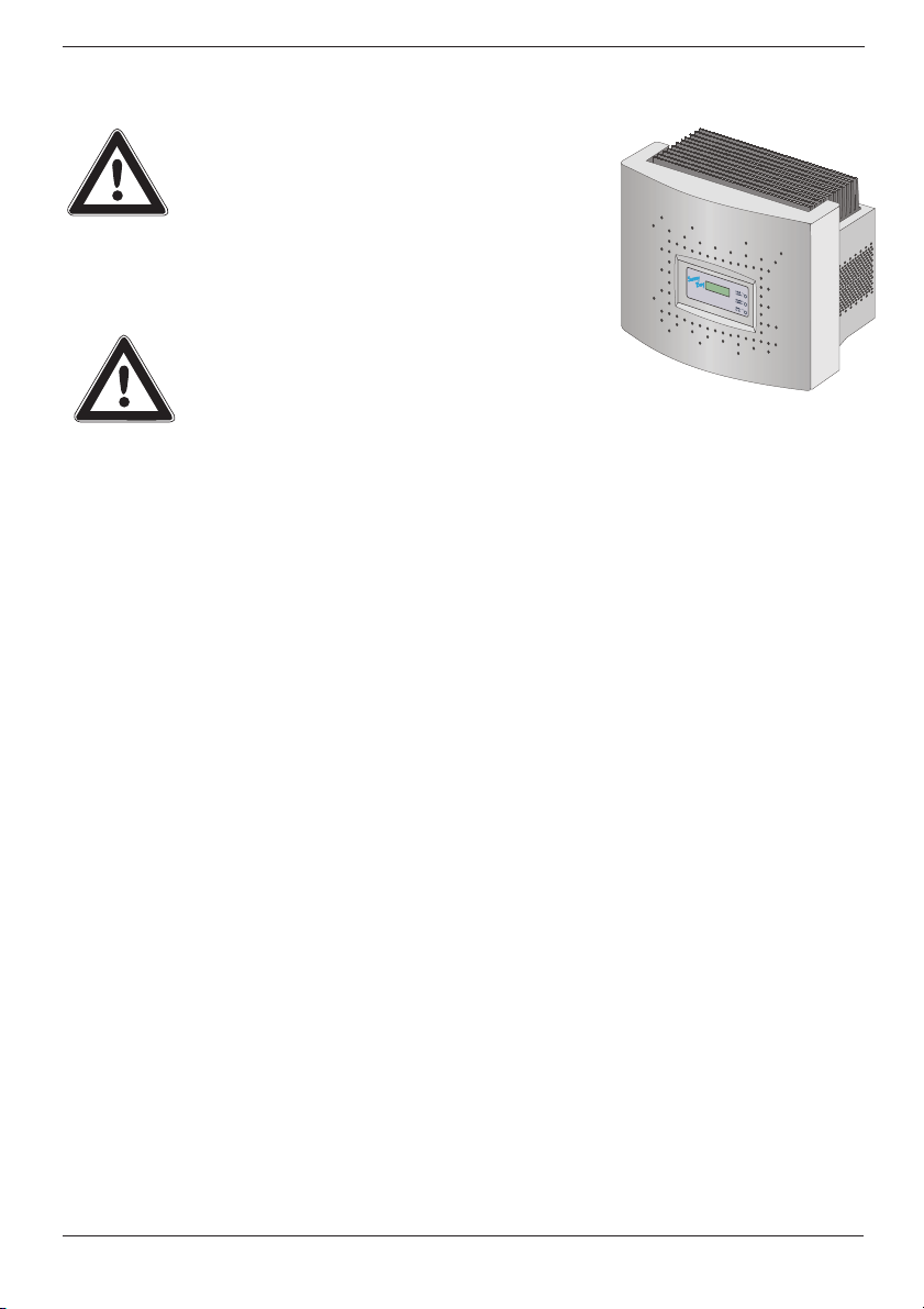
Installation Guide Safety Instructions
2Safety Instructions
Only a qualified electrician may work on the
open Sunny Boy! This work is only permissible
if the AC and DC power supply are safely
disconnected from the Sunny Boy.
The Sunny Boy must be disconnected from the grid and secured
against accidental reconnection. Connections to the PV
generator must be disconnected as well.
When this has been done, always wait for
approx. 5 minutes so that the capacitors in the
Sunny Boy can be discharged. Only then may
the lid be opened and the safe isolation from
power supply be checked.
The Sunny Boy 2800i is equipped with the anti-islanding unit
„SMA grid guard“. The Sunny Boy 2800i therefore complies
with the VDEW guidelines for grid interactive inverters and the
DIN VDE 0126 (4.99) specified in this regulation.
The Sunny Boy is equipped with high
voltage capacitors that can contain lethal
voltages even when disconnected from
supply power for some time.
SB2800i-11:SE0504 SMA Regelsysteme GmbH 5
Page 8

Safety Instructions Installation Guide
6 SMA Regelsysteme GmbH SB2800i-11:SE0504
Page 9
Installation Guide Overview
3 Overview
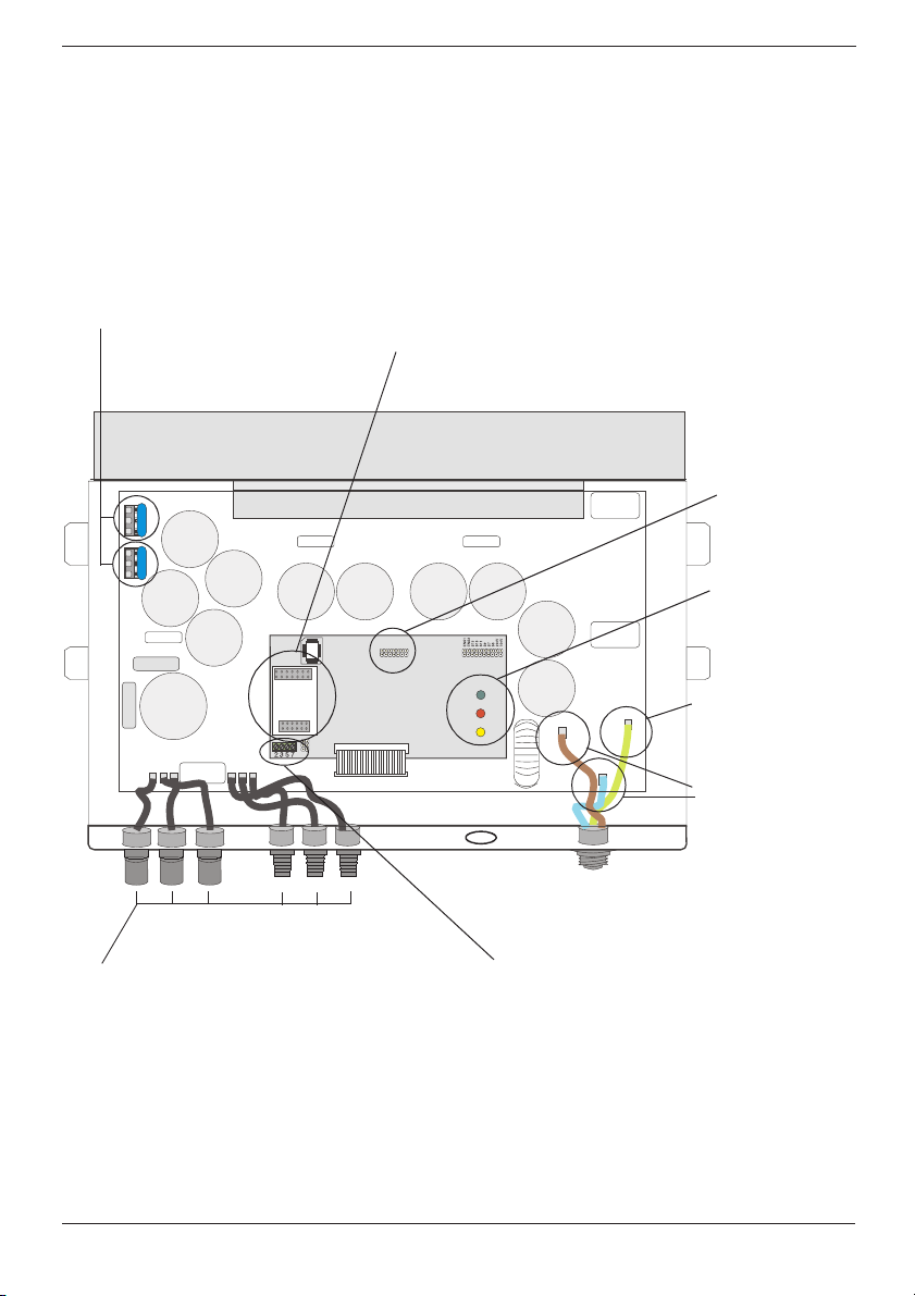
3.1 Device Description
The following figure shows the different components and
connection areas of an open Sunny Boy 2800i inverter.
Varistors,
page 31
Communication socket
(RS232, RS485, PLC),
page 25
Socket for
display unit
(Sunny Display)
LEDs indicating
operating state
Terminal for PE
Terminals (AC)
page 17
PV input plugs (DC),
page 19
Fig. 3.1: Inside view of the Sunny Boy 2800i
SB2800i-11:SE0504 SMA Regelsysteme GmbH 7
Communication
terminal
Page 10
Overview Installation Guide
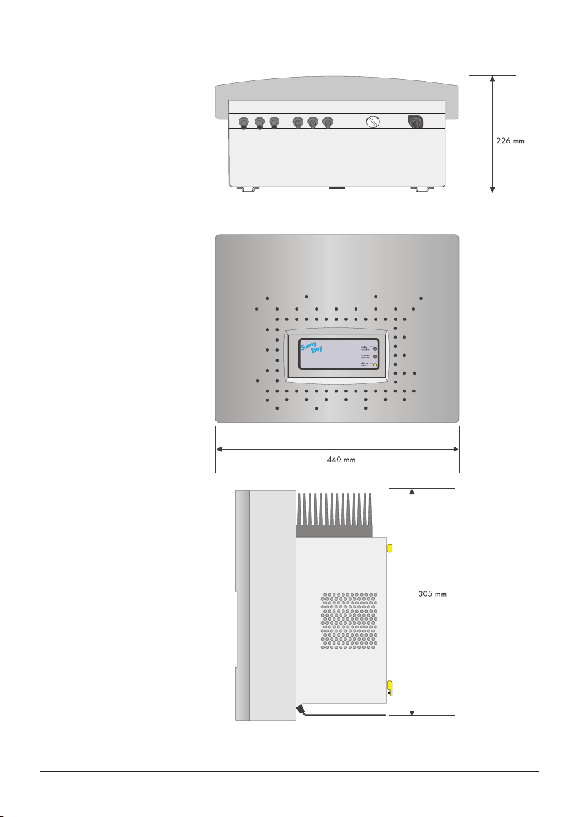
3.2 External Dimensions
Abb. 3.2: Size of the Sunny Boy 2800i
8 SMA Regelsysteme GmbH SB2800i-11:SE0504
Page 11
Installation Guide Requirements for the Installation
4 Requirements for the Installation
Please make sure to fulfill all conditions below before installing
and commissioning the Sunny Boy.
4.1 Requirements: Mounting Place
The Sunny Boy 2800i has a relatively high weight of 31 kg.
Please keep this in mind when selecting the place where and how
to mount the Sunny Boy.
The ambient temperature should be within -25 °C
and + 60 °C.
The Sunny Boy 2800i is only for inside installation. It should be
mounted in a place whithout high temperatures - otherwise this
may reduce the yield of the PV plant.
It can be mounted straight or to the back. To ensure optimum
energy yield and easy operation it should be mounted straight
and on eye level.
Important for the selection of the location:
Unintended removal of the Multi-Contact
snap-cable connectors can damage the
connectors and even result in serious injuries.
Install the Sunny Boy in a place where an
unintended removal of the Multi-Contact
connectors (e. g. by children) is not possible.
Some parts of the Sunny Boy can reach
temperatures over 80 °C. Keep a suitable
distance to flammable materials!
Never install the Sunny Boy in areas that likely
contain explosive athmospheres (battery
rooms, fuel storage rooms etc.)!
31 kg
®
®
Install the Sunny Boy 2800i in a fairly dust free
environment.
SB2800i-11:SE0504 SMA Regelsysteme GmbH 9
Page 12
Requirements for the Installation Installation Guide
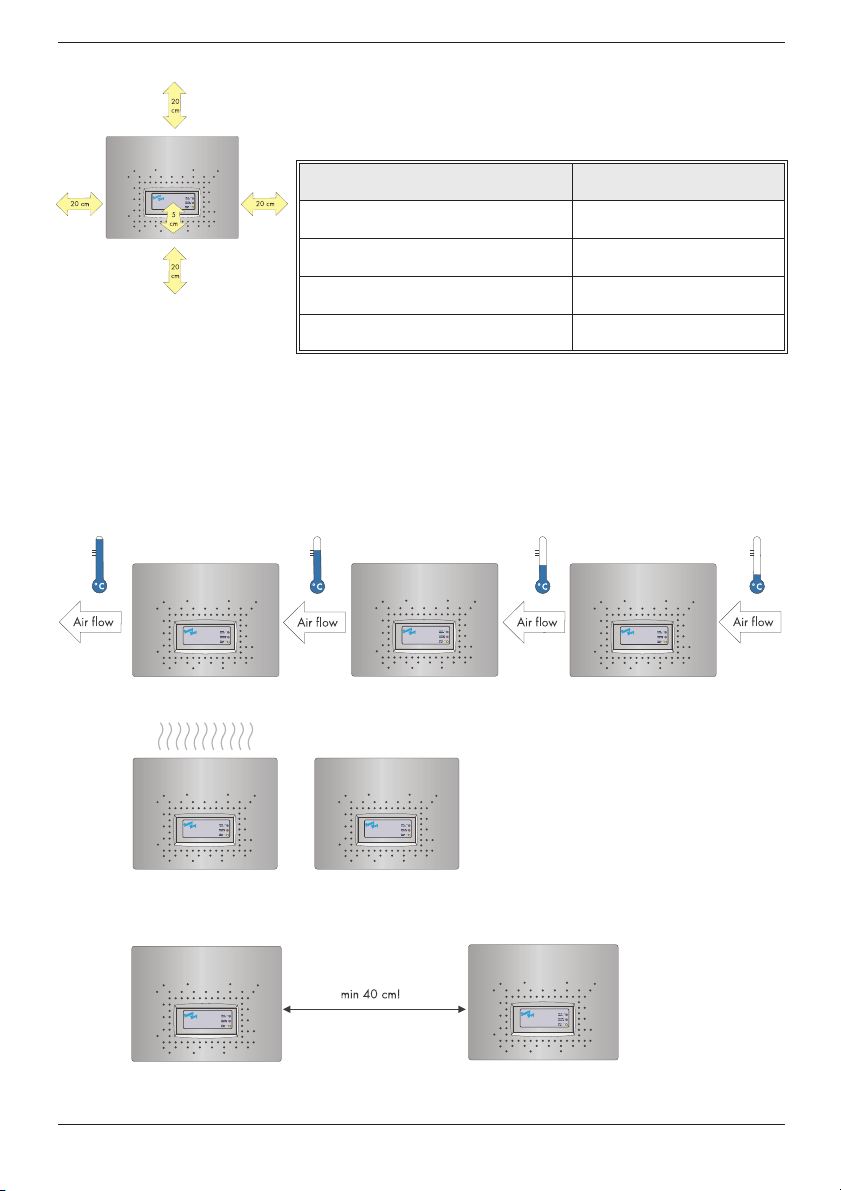
Please make sure there is a sufficient space for heat dissipation!
In a normal environment the following clearance should be
provided for a single Sunny Boy 2800i
Minimum clearance
Lateral 20 cm
Top 20 cm
Pay attention to the required minimum
clearance for the Sunny Boy 2800i
Bottom 20 cm
Front 5 cm
Table 4.1: Minimum clearance
If you want to install several Sunny Boy 2800i side by side on the
same level, pay attention to the minimum distance between them.
If there is not enough space between the devices, the left Sunny
Boy will reduce the yield of the PV plant because of the
incomming air temperature.
Two or more Sunny Boy 2800i
may not be mounted directly to
each other.
The minimum space between two Sunny Boy 2800i has to be
40 cm.
10 SMA Regelsysteme GmbH SB2800i-11:SE0504
Page 13

Installation Guide Requirements for the Installation
In a living area the Sunny Boy should not be mounted on plaster
panels, thin wooden panels etc. in order to avoid noises.
We recommend to install the inverter on a firm and sturdy
surface.
Mounting the Sunny Boy on a thin sur-
face may emit a slight noise!
SB2800i-11:SE0504 SMA Regelsysteme GmbH 11
Page 14

Requirements for the Installation Installation Guide
4.2 Requirements: PV-Modules
The Sunny Boy 2800i is designed for the connection of up to three
strings (PV modules connected in series).
The „ GenAu“ tool will help to dimension and check the size of
your strings with respect to the Sunny Boy you intend to use. The
„GenAu“ tool is available for download at www.SMA.de.
The device has six Multi-Contact plug connectors (two for each
string). The connecting cables of the PV panel therefore have to
be equipped with such plug connectors as well.
A connection kit for connection of loose cable ends in a string can
be purchased as an accessory (SMA order name: „SWR-MC“).)
Limits for DC input
Max. voltage 600 V (DC)
12 SMA Regelsysteme GmbH SB2800i-11:SE0504
Page 15

Installation Guide Requirements for the Installation
4.3 Requirements: Grid 230 V~ (AC)
The relevant technical regulations as well as specific requirements
defined by the local public utility have to be complied with.
The terminals of the Sunny Boy 2800i are suitable for cables with
a cross-section of up to 2.5 mm². The Sunny Boy is connected with
three wires (L, N, PE).
Each connection to a Sunny Boy 2800i must be
equipped with a separate circuit breaker 16 A.
No other consumers may be connected to the
cable.
The Sunny Boy has to be connected
to grid with three wires!
No additional consumers may be
connected between the Sunny Boy
and the fuse!
SB2800i-11:SE0504 SMA Regelsysteme GmbH 13
Page 16

Requirements for the Installation Installation Guide
The impedance at the AC connection point of the Sunny Boy
3000 must be below 2 Ohm in order to ensure a reliable function
of the anti-islanding unit. You should furthermore have a suitable
cable cross-section in order to keep the losses below 1 % at
nominal power. The according losses with respect to cable length
and cross-section are illustrated below:
Fig. 4.1: Losses in AC cable
The Sunny Boy 2800i is designed for 230 V grids. The voltage
should be within 198 V and 260 V and the frequency should be
198 V ... 260 V
49.8 Hz ... 50.2 Hz
within 49.8 Hz and 50.2 Hz.
Limits for AC Output
Limits for AC output
Voltage range 198 V ... 260 V
Frequency range 49.8 Hz ... 50.2 Hz
Voltage range
(without ENS)
Frequency range
(without ENS)
180 V ... 260 V
45.5 Hz ... 54.5 Hz
Table 4.2: Limits for AC output of the Sunny Boy 2800i
14 SMA Regelsysteme GmbH SB2800i-11:SE0504
Page 17

Installation Guide Installation
5 Installation
5.1 Mounting
For trouble-free mounting of the Sunny Boy 2800i we recommend
to use the bracket for wall installation included in delivery. You
can mount it vertically in firm concrete or stone walls with e. g.
stainless steel 8 mm x 50 mm hexagon screws according to DIN
571 and with dowels type SX8.
Keep the weight of the Sunny Boy 2800i (31 kg) in mind.
1. Mount the bracket. To mark the positions for drill holes you
can also use the bracket as a drilling template.
2. Hang the upper fixing straps on the Sunny Boy 2800i into
the bracket (2) so that it cannot be shifted sideways any
more.
3. Secure the Sunny Boy 2800i against lifting off by screwing
the M6x10 screw (included in delivery) into the lower middle
fixing strap (3).
4. Ensure that the Sunny Boy 2800i has been tightly fastened.
SB2800i-11:SE0504 SMA Regelsysteme GmbH 15
Page 18

Installation Installation Guide
5.2 Electrical Installation
The following figure shows the complete cabling of a Sunny Boy
2800i:
Depending on the type of PV module used, it is reasonable to
connect only one String or to use two or three parallel Strings.
Thus, the module has three plus poles and three minus poles.
These poles are simply connected in parallel within the inverter.
In case only one String terminal is used, please
cover the four plug-in contacts not used with the
seals enclosed.
16 SMA Regelsysteme GmbH SB2800i-11:SE0504
Page 19

Installation Guide Installation
Connecting of AC output
Please follow the steps below:
1. Disconnect the grid (switch off the circuit breaker), secure it
against accidental reactivation and ensure that it is disconnected.
Before opening the Sunny Boy check
2. The AC connector is a round socket that is suitable to take
different cable diameters. A PG13.5 and a PG16 cable seal
are included with the AC connection socket. Check which
size is suitable for your AC connection cable.
3. Strip the insulation off the ends of the cable and connect the
cable to the AC socket as shown below.
whether the AC output is safely isola-
ted from supply!
4. Push the rubber ring into the fastening case.
5. Put the cable through the PG13.5 or 16 cable seal. Put the
cable through the fastening case with the rubber ring and
through the socket tube.
6. Connect the wires of the AC cable as follows:
• Protective Earth (PE) to the terminal with the „ground“ symbol.
• Neutral wire to the terminal marked with „1“
• Phase L to the terminal marked with „2“
• The terminal marked with „3“ is not used.
7. Make sure that all wires are firmly connected.
8. Push the socket tube firmly onto the socket.
SB2800i-11:SE0504 SMA Regelsysteme GmbH 17
Page 20

Installation Installation Guide
9. For cables that require the PG16 gland: Tighten the bolt of the PB16 gland.
10.The AC connector socket is now ready to use.
11.Seal the AC connector socket in case you do not insert it into the Sunny Boy.
12.The AC connector socket can be inserted into the Sunny Boy
in case the Sunny Boy is already mounted in the correct position. Remove the seal from the AC connector on the Sunny
Boy, insert the AC connector plug and tighten the seal.
Do not switch on the circuit breaker yet! The
Sunny Boy 2800i may only be connected to the
AC grid when the PV strings have been
connected and the device is tightly closed.
18 SMA Regelsysteme GmbH SB2800i-11:SE0504
Page 21

Installation Guide Installation
PV string (DC) connection
Connect the PV strings as follows:
1. Check the PV generator connections on their correct polarity
and compliance with the maximum string voltage of 600 V
DC, see chapter 4.2 "Requirements: PV-Modules" (p. 12).
The voltage from the strings is very dangerous!
Be very careful and pay attention to all
applicable safety regulations!
2. Measure the DC voltages between each Multi-Contact plug
connector of a string and ground potential. Follow the safety
instructions!
3. If the voltages you measured is constant and more than a few
volts, a ground fault has occured in this string. The ratios of
voltages approximately indicate where the ground fault can
be found.
When you have found a ground fault in a
string, only connect it to the Sunny Boy 2800i
after you have removed the cause for the
ground fault in the PV generator.
4. Repeat steps 2 and 3 for each string.
5. Connect the trouble-free PV strings to the Sunny Boy. Make
sure to connect them to the correct terminals and with correct
polarization.
When connecting the plus and minus
poles of a string make sure to choose
the correct connection!
SB2800i-11:SE0504 SMA Regelsysteme GmbH 19
Page 22

Installation Installation Guide
If the lower yellow LED repeatedly blinks once
a second for four times, immediately disconnect
the grid voltage and the PV generator from the
Sunny Boy 2800i. The input voltage is too high.
The inverter might be damaged!
Check whether string voltages comply with limiting values stated
in chapter 4.2 "Requirements: PV-Modules" (p. 12). If the values
are too high, the planner / installer of the PV generator must
modify the strings.
If the LED blinks again when the PV plant is reconnected to the
inverter although string voltages have been checked to be ok,
disconnect the PV panel again and contact SMA Regelsysteme
GmbH (see chapter 9 "Contact" (p. 35)).
20 SMA Regelsysteme GmbH SB2800i-11:SE0504
Page 23

Installation Guide Installation
5.3 Activation
You can activate the Sunny Boy 2800i when:
• The AC (grid) cable has been correctly connected.
• All the DC (PV) strings have been connected and all unused
DC plug connectors on the underside of the inverter have
been closed with the protecting caps.
• The lid has been tightly screwed on.
Proceedings for activation
1. Switch the circuit breaker on.
2. Check whether the LEDs indicate trouble-free operation of the
Sunny Boy 2800i based on the following table. If this is the
case commissioning has been successfully completed.
.
SB2800i-11:SE0504 SMA Regelsysteme GmbH 21
Page 24

Installation Installation Guide
Green Red Yellow Status
off off OK (feeding)
permanently on
blinking fast
(3 x per second)
blinking slowly
(1 x per second)
shortly turns off
(approx. 1 x per
second)
off
permanently on
off failure
permanently on OK (initialization)
off off OK (stop)
permanently on off failure
off off
OK (waiting, grid
monitoring)
permanently on off failure
off off OK (derating)
permanently on off failure
off OK (stand-by)
off
on/blinking failure
off failure
permanently on
on/blinking failure
Table 5.1: LED blinking codes
You will find a detailed description of failure messages and their
causes in the „ Operating Instructions“.
22 SMA Regelsysteme GmbH SB2800i-11:SE0504
Page 25

Installation Guide Opening and closing the Sunny Boy
6 Opening and closing the Sunny Boy
When the inverter has to be openend always
follow the safety instructions given in chapter 2
"Safety Instructions" (p. 5).
6.1 Opening the Sunny Boy
Caution: Stick to the order specified below!
1. Switch off the AC connection.
2. Disconnect the PV generator from the Sunny Boy 2800i, by pulling off all the connectors.
3. Wait 5 minutes! (This is necessary to let the internal capacitors discharge.)
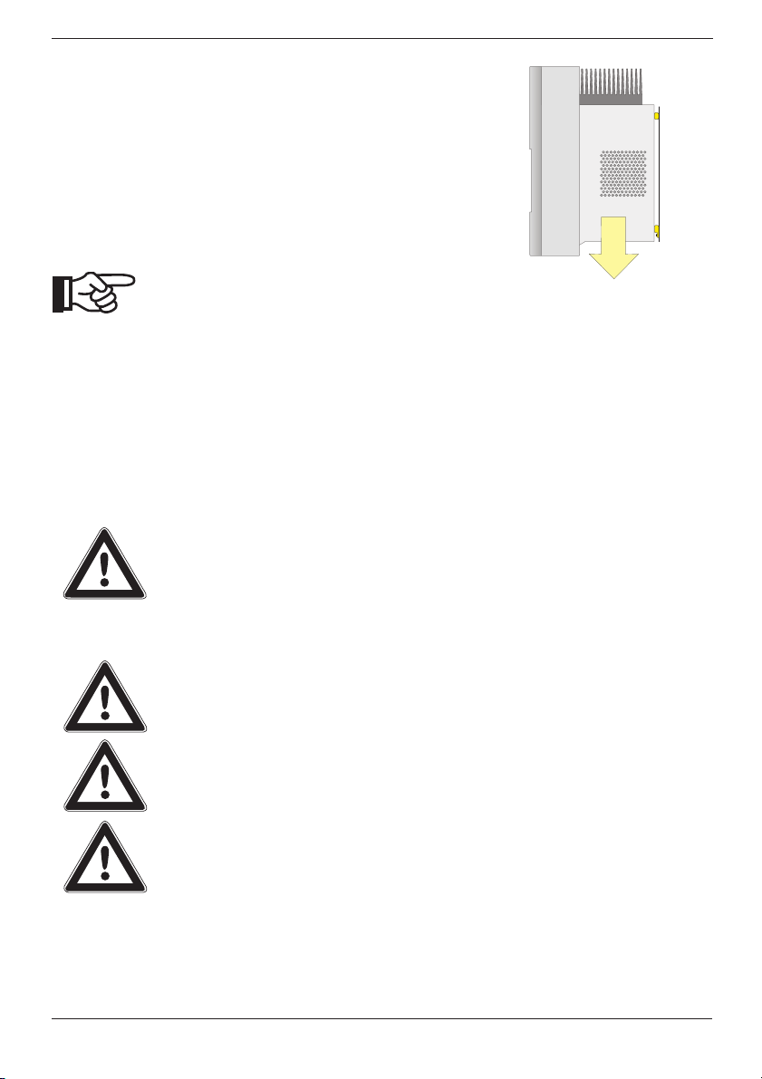
4. Unscrew the lid from the enclosure of the Sunny Boy 2800i.
The screws are on the underside of the Sunny Boy.
5. Pull down the lid carefully (approx. 4 cm)
6. and carefully move the lid forward. Then pull the PE cable off the inside of the lid.
Make sure that you pull off the green-
yellow PE cable from the inside of the
Sunny Boy when you open it!
SB2800i-11:SE0504 SMA Regelsysteme GmbH 23
Page 26

Opening and closing the Sunny Boy Installation Guide
6.2 Closing the Sunny Boy
Caution: Stick to the order specified below!
1. Connect the PE conductor to the lid. Then attach the lid to the
enclosure of the Sunny Boy 2800i by tightening the two
screws.
2. Connect the PV generator. Make sure to connect each plug to the correct terminal.
3. Switch on the circuit breaker. This activates the Sunny Boy 2800i.
4. Check whether the LEDs of the Sunny Boy 2800i indicate trouble-free operation.
24 SMA Regelsysteme GmbH SB2800i-11:SE0504
Page 27

Installation Guide Communication
7Communication
The upgrading of your Sunny Boy 2800i with communication
Piggy-Backs is described in the manuals delivered with the
communication Piggy-Backs.
You can see whether the Sunny Boy 2800i has already been
equipped with a communication interface in the factory by
checking the order name on the delivery note.
„-0xx“ without interface
„-1xx“ PLC modem (Powerline Communication)
„-2xx“ RS232 interface
„-3xx“ RS485 interface
7.1 Powerline Communication
The following conditions must be fulfilled for Powerline
Communication:
• The Sunny Boy 2800i has to be equipped with the „ PLC signal
unit“ (see chapter 3.1 "Device Description" (p. 7)).
The Sunny Boy 2800i can be upgraded for powerline
communication. The ordering code for the powerline upgrade kit
for the Sunny Boy 2800i inverter is „ NLMPB-NR“.
SB2800i-11:SE0504 SMA Regelsysteme GmbH 25
Page 28

Communication Installation Guide
7.2 RS232 Communication
RS232 is a communication standard for transmission paths up to
15 m to one single Sunny Boy 2800i. The following conditions
must be fulfilled for RS232 communication.
• The Sunny Boy 2800i has to be equipped with a second cable
gland (included in delivery) between the PV input plugs and
the cable opening for AC output on its underside.
• The Sunny Boy 2800i has to be equipped with an RS232 Piggy-Back. The ordering code for the RS232 is 232PB-NR
• A cable with a minimum of three wires and common shield,
such as LiYCY, 0.25 mm² cross-section and a maximum 15 m
length has to be used.
To provide for an RS232 interface the Sunny Boy 2800i has to be
equipped with the second cable gland included in delivery. The
RS232 cable enters the inverter through this gland and is
connected to the communication terminal within the Sunny Boy
2800i (see chapter 3.1 "Device Description" (p. 7)). Its other end
is usually connected to a serial interface of a PC. The following
table specifies the pin designation for standard PC terminals.
Terminal Signal
D-SUB 9
plug (PC)
D-SUB 25
plug (PC)
Enclosure Shielding Enclosure Enclosure
2
3
RxD (Sunny Boy
output port)
TxD (Sunny Boy
input port)
23
32
5GND57
26 SMA Regelsysteme GmbH SB2800i-11:SE0504
Page 29

Installation Guide Communication
Abb. 7.1: Sunny Boy connected to a PC via RS232
SB2800i-11:SE0504 SMA Regelsysteme GmbH 27
Page 30

Communication Installation Guide
7.3 RS485 Communication
RS485 is a communication standard for up to 50 Sunny Boy
inverters with a total cable length of up to 1200 m. The following
conditions must be fulfilled for RS485 communication:
• All Sunny Boys have to be equipped with the second cable
gland (included in delivery) on their underside.
• All Sunny Boys have to be equipped with an
RS485 Piggy-Back.
• A cable with common shield (such as LiYCY) with two twisted
pair with a line impedance of 100 ohm.
• The first and the last participant of the RS485 bus have to be
equipped with a termination resistor.
• The ordering code for the RS485 is 485PB-NR
At the moment the Sunny Boy Control and the Sunny
Boy Control Plus can communicate with PV-plants
with up to 5 different types and all in all 50 Sunny
Boy inverters in total. The Sunny Boy Control Light can
communicate with 5 different Sunny Boy types and all in all 20
Sunny Boy inverters in total.
To provide for an RS485 interface the Sunny Boy 2800i has to be
equipped with the second cable gland included in delivery. The
delivery includes two different gland fittings (a fitting with one
hole for one cable and a fitting with two holes for two cables).
Best start with the last Sunny Boy 2800i in the communication
chain (i. e. the one at the end of the RS485 cable):
1. Use the gland fitting with one hole.
2. Now attach one of the two plug connectors delivered to the
data cable. Connect the wires of one twisted pair to terminals 2 and 7 on the communication slot (see Fig. 7.2: "One
or several Sunny Boys connected with an RS485 cable to a
PC with interface converter." (p. 30)). Write down which
wire is connected to which terminal!
3. Connect one (or both) wires of the second twisted pair to ter-
minal 5 on the communication slot. Write down which
wire(s) you have used!
4. If no other inverters have to be connected,
continue with point 8.
5. Now connect the next inverter. Use the contact
units with two holes.
28 SMA Regelsysteme GmbH SB2800i-11:SE0504
Page 31

Installation Guide Communication
6. Connect the wires of a cable to the terminals on the communication slot with the same allocation as written down for the
first inverter. This applies both to the wires in the cable
coming from the last inverter and in the one running to the
next inverter. Proceed with special care! Finding wiring
failures can be very frustrating!
7. Repeat points 5 and 6 for each Sunny Boy to be connected.
8. To be able to connect them to a Sunny Boy Control or a PC
with an interface converter later, label the wires at the end of
the cable as follows.
Terminal
D-SUB 9
plug
Labeling of
wire
Your wire
labeling
Enclosure Enclosure Shielding
2 3 Data +
7 8 Data -
55GND
The connection of one or several Sunny Boy inverters to a
Sunny Boy Control is described in detail in the manual of the
Sunny Boy Control.
SB2800i-11:SE0504 SMA Regelsysteme GmbH 29
Page 32

Communication Installation Guide
Fig. 7.2: One or several Sunny Boys connected with an RS485
cable to a PC with interface converter.
SMA reccomends the usage of a I-7520 interface converter for
the connection of an RS485 bus to a PC. SMA does not support
any other types.
30 SMA Regelsysteme GmbH SB2800i-11:SE0504
Page 33

Installation Guide Exchanging varistors
8 Exchanging varistors
The Sunny Boy 2800i is a very complex technical device.
Therefore there are only a few possibilities to repair failures on
site. Please do not try to make repairs other than described in this
document. Make use of our 24-hour exchange service and the
repair service of SMA Regelsysteme GmbH.
If the red status LED is permanently on during operation please
first make sure that there is no ground fault in the PV generator.
1. Disconnect the grid (switch off the circuit breaker), secure it
against accidental reactivation and ensure that it is disconnected.
Ensure that the AC voltage is off before you open the Sunny Boy!
2. Disconnect the Multi-Contact plug connectors of all strings.
Make sure that their allocation to the different inverter input
ports can still be recognized!
Disconnect the PV strings!
3. Measure voltages between one Multi-Contact plug connector
of each string and the ground potential. Follow all applicable
safety instructions!
The voltage from the strings is very dangerous!
Be very careful and pay attention to all
applicable safety regulations!
Measure voltages between
Multi-Contact plug connectors and
the ground potential.
4. If the voltages measured are constant and their total is
approximately equal to the open-circuit voltage of the string,
there is a ground fault in this string. Its appoximate position
can be deducted from the ratios of voltages.
5. Repeat points 3 and 4 for each string.
If you have found a ground fault it is probably unnecessary
to exchange the varistors. Make sure to remove the ground
fault instead. This should normally be done by the installer of
the PV panel. In this case proceed with point 10, but without
reconnecting the faulty string! Protect its Multi-Contact plug
connectors against touching (e. g. by protective caps or insulation strip with sufficient electric strength).
SB2800i-11:SE0504 SMA Regelsysteme GmbH 31
Page 34

Exchanging varistors Installation Guide
If you have not found any ground fault in the PV generators,
probably one of the thermally monitored varistors has lost its
protective function. The varistors are subject to wear and tear
and their function is reduced in the course of their aging or
in case of repeated strain placed on them by surge voltages.
You can now check the varistors as described below while
following the safety instructions given in chapter 2 "Safety
Instructions" (p. 5).
6. Unscrew the lid of the Sunny Boy 2800i and remove it. Disconnect the PE plug inside the lid. Test safe isolation from
supply.
7. Test all varistors for an electric connection between terminals
2 and 3. If there is no electric connection the varistor is useless. The position of varistors in the Sunny Boy 2800i can be
seen in the figure in chapter 3.1 "Device Description" (p. 7).
8. Replace the defective varistor by a new one as shown in the
figure on the left. Ensure correct orientation of the varistor!
Please contact SMA if you have not received special tools to
move the terminals (included in delivery of replacement
varistors). However, the terminal contacts can also provisionally be released one by one with a suitable screwdriver. The
failure of a varistor is normally due to circumstances that
apply to all varistors in a similar manner (temperature, age,
induced surge voltages). We therefore strongly recommend
not only to exchange the defective one, but all two. These
varistors are specially manufactured for use in the Sunny Boy
2800i and are not commercially available. They have to be
purchased from SMA Regelsysteme GmbH direct (SMA
order name:“SB-TV4“).
The input port thus modified is no longer
protected against surge voltages! Equip the
inverter with varistors again as soon as
possible. The inverter should not be
operated without varistors in plants where
there is a high risk of surge voltages!
9. Reconnect the PE plug to the lid and close the Sunny Boy 2800i again.
10.Connect the faultless strings of the PV panel. Ensure correct allocation to strings.
32 SMA Regelsysteme GmbH SB2800i-11:SE0504
Page 35

Installation Guide Exchanging varistors
11.Switch on the circuit breaker.
12.Check whether the LEDs of the Sunny Boy 2800i show trouble-free operation.
If you have found neither a ground fault nor a defective varistor
there probably is a fault in the inverter. Please contact the SMA
hotline in this case to discuss further proceedings.
SB2800i-11:SE0504 SMA Regelsysteme GmbH 33
Page 36

Exchanging varistors Installation Guide
34 SMA Regelsysteme GmbH SB2800i-11:SE0504
Page 37

Installation Guide Contact
9Contact
If you have any questions or technical problems with the Sunny
Boy 2800i our hotline will be happy to help you. Please keep the
following data ready when calling SMA:
• Type of inverter used
• Connected modules
•Communication
•Serial number of device
Address: SMA Regelsysteme GmbH
Hannoversche Straße 1 - 5
34266 Niestetal
Germany
Tel.:+49 (561) 95 22 - 499
Fax:+49 (561) 95 22 - 4699
hotline@SMA.de
www.SMA.de
SB2800i-11:SE0504 SMA Regelsysteme GmbH 35
Page 38

Contact Installation Guide
36 SMA Regelsysteme GmbH SB2800i-11:SE0504
Page 39

Page 40

SMA Regelsysteme GmbH
www.SMA.de
Hannoversche Str. 1-5
34266 Niestetal
Germany
Tel. +49 561 9522 -0
Fax +49 561 9522 -100
www. SMA.de
 Loading...