

Page 1
CA
US
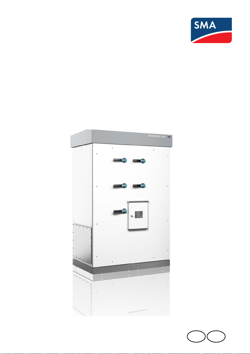
AC/DC Disconnect Unit
Disconnect Unit for Sunny Central 250U/500U/
500HE‑US and Sunny Central CP
Unpacking
DISU_SCUS-AP-eng-IUS110911 | 98-4051011 | Version 1.1
Page 2

Page 3

SMA America, LLC Legal Restrictions
Copyright © 2011 SMA America,LLC. All rights reserved.
No part of this document may be reproduced, stored in a retrieval system, or transmitted, in any form
or by any means, electronic, mechanical, photographic, magnetic or otherwise, without the prior
written permission of SMA America,LLC.
Neither SMA America,LLC nor SMA Solar Technology Canada Inc. makes representations, express
or implied, with respect to this documentation or any of the equipment and/or software it may
describe, including (with no limitation) any implied warranties of utility, merchantability, or fitness for
any particular purpose. All such warranties are expressly disclaimed. Neither SMA America,LLC nor
its distributors or dealers nor SMA Solar Technology Canada Inc. nor its distributors or dealers shall
be liable for any indirect, incidental, or consequential damages under any circumstances.
The exclusion of implied warranties may not apply in all cases under some statutes, and thus the
above exclusion may not apply.)
Specifications are subject to change without notice. Every attempt has been made to make this
document complete, accurate and up-to-date. Readers are cautioned, however, that
SMAAmerica,LLC and SMA Solar Technology Canada Inc. reserve the right to make changes
without notice and shall not be responsible for any damages, including indirect, incidental or
consequential damages, caused by reliance on the material presented, including, but not limited to,
omissions, typographical errors, arithmetical errors or listing errors in the content material.
All trademarks are recognized even if these are not marked separately. Missing designations do not
mean that a product or brand is not a registered trademark.
The Bluetooth
®
word mark and logos are registered trademarks owned by Bluetooth SIG, Inc. and
any use of such marks by SMA America,LLC and SMA Solar Technology Canada Inc. is under
license.
SMA America, LLC
3801 N. Havana Street
Denver, CO 80239 U.S.A.
SMA Solar Technology Canada Inc.
2425 Matheson Blvd. E, 8th Floor
Mississauga, ON L4W 5K5, Canada
Unpacking DISU_SCUS-AP-eng-IUS110911 3
Page 4
Important Safety Instructions SMA America, LLC
%"/(&3
8"3/*/(
$"65*0/
/05*$&
IMPORTANT SAFETY INSTRUCTIONS
SAVE THESE INSTRUCTIONS
This manual contains important instructions for the DisconnectUnit for Sunny Central 250U/500U/
500HE-US and Sunny Central CP, that must be followed during installation and maintenance of the
pv inverter.
The DisconnectUnit for Sunny Central 250U/500U/500HE-US and Sunny Central CP is designed
and tested according to international safety requirements, but as with all electrical and electronic
equipment, certain precautions must be observed when installing and/or operating the Disconnect
Unit for DisconnectUnit for Sunny Central 250U/500U/500HE-US and Sunny Central CP. To
reduce the risk of personal injury and to ensure the safe installation and operation of the Disconnect
Unit for SunnyCentral 250U/500U/500HE-US and Sunny Central CP, you must carefully read and
follow all instructions, cautions and warnings in this technical description.
Warnings in this document
A warning describes a hazard to equipment or personnel. It calls attention to a procedure or practice,
which, if not correctly performed or adhered to, could result in damage to or destruction of part or all
of the SMA equipment and/or other equipment connected to the SMA equipment or personal injury.
DANGER indicates a hazardous situation which, if not avoided, will result in death or serious injury.
WARNING indicates a hazardous situation which, if not avoided, could result in death or serious
injury.
CAUTION indicates a hazardous situation which, if not avoided, could result in minor or moderate
injury.
NOTICE is used to address practices not related to personal injury.
4 DISU_SCUS-AP-eng-IUS110911 Unpacking
Page 5
SMA America, LLC Important Safety Instructions
Other symbols in this document
In addition to the safety and hazard symbols described on the previous pages, the following symbol
is also used in this technical description:
Information
This symbol accompanies notes that call attention to supplementary information that you should
know and use to ensure optimal operation of the system.
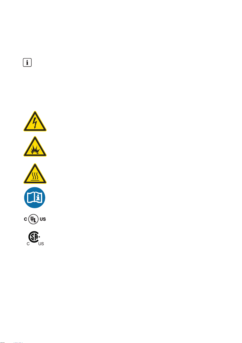
Markings on this product
The following symbols are used as product markings with the following meanings.
Warning regarding dangerous voltage
The product works with high voltages. All work on the product must only be performed
as described in the documentation of the product.
Electric arc hazards
The product has large electrical potential differences between its conductors. Arc flashes
can occur through air when high-voltage current flows. Do not work on the product
during operation.
Beware of hot surface
The product can become hot during operation. Do not touch the product during
operation.
Observe the operating instructions
Read the documentation of the product before working on it. Follow all safety
precautions and instructions as described in the documentation.
UL1741 is the standard applied by Underwriters Laboratories to the Disconnect Unit for
Sunny Central 250U/500U/500HE-US and Sunny Central CP to certify that it meets the
requirements of the NationalElectricalCode
®
, the Canadian Electrical Code® CSA
C22.1 and IEEE‑929‑2000. IEEE 929-2000 provides recommendations regarding the
proper equipment and functionality necessary to ensure compatible operation when
power generation is connected to the utility grid.
Unpacking DISU_SCUS-AP-eng-IUS110911 5
Page 6

General Warnings SMA America, LLC
8"3/*/(
General warnings
All electrical installations must be done in accord ance w ith th e local and NationalElectrical Code®
ANSI/NFPA 70 or the Canadian Electrical Code® CSAC22.1.
Before installing or using the Disconnect Unit for Sunny Central 250U/500U/500HE-US and
Sunny Central CP, read all of the instructions, cautions, and warnings on the Disconnect Unit for
Sunny Central 250U/500U/500HE-US and Sunny Central CP in this technical description.
Before connecting the Disconnect Unit for Sunny Central 250U/500U/500HE-US and Sunny
Central CP to the power distribution grid, contact the local power distribution grid company. This
connection must be made only by qualified personnel.
Wiring of the Disconnect Unit for Sunny Central 250U/500U/500HE-US and Sunny Central CP
must be made by qualified personnel only.
6 DISU_SCUS-AP-eng-IUS110911 Unpacking
Page 7

SMA America, LLC Table of Contents
Table of Contents
1 Information on this Manual. . . . . . . . . . . . . . . . . . . . . . . . . 9
2 Scope of Supply . . . . . . . . . . . . . . . . . . . . . . . . . . . . . . . . . 10
3 Storage . . . . . . . . . . . . . . . . . . . . . . . . . . . . . . . . . . . . . . . . 11
4 Transport Packaging . . . . . . . . . . . . . . . . . . . . . . . . . . . . . 12
4.1 Transport Packaging and Center of Gravity . . . . . . . . . . . . . . . 12
4.2 Symbols on the Transport Packaging . . . . . . . . . . . . . . . . . . . . 14
4.3 Technical Data for the Transport Packaging . . . . . . . . . . . . . . . 14
5 Transporting the Packaged Disconnect Unit . . . . . . . . . . 15
6 Unpacking the Disconnect Unit . . . . . . . . . . . . . . . . . . . . . 16
6.1 Removing the Film . . . . . . . . . . . . . . . . . . . . . . . . . . . . . . . . . . . 16
6.2 Removing the Lashing Straps . . . . . . . . . . . . . . . . . . . . . . . . . . 17
6.3 Removing the Clamping Bands. . . . . . . . . . . . . . . . . . . . . . . . . 18
6.4 Removing the Box Components . . . . . . . . . . . . . . . . . . . . . . . . 18
7 Transporting the Disconnect Unit Without Packaging . . 21
7.1 Transporting the Disconnect Unit Using a Crane . . . . . . . . . . . 21
7.2 Transporting the Disconnect Unit Using a Forklift Truck . . . . . . 22
8 Preparing the Disconnect Unit for Installation . . . . . . . . . 25
8.1 Opening the Disconnect Unit . . . . . . . . . . . . . . . . . . . . . . . . . . 25
8.2 Mounting the Lid . . . . . . . . . . . . . . . . . . . . . . . . . . . . . . . . . . . . 28
8.3 Closing the Disconnect Unit . . . . . . . . . . . . . . . . . . . . . . . . . . . 29
9 Contact . . . . . . . . . . . . . . . . . . . . . . . . . . . . . . . . . . . . . . . . 33
Unpacking DISU_SCUS-AP-eng-IUS110911 7
Page 8

SMA America, LLC
8 DISU_SCUS-AP-eng-IUS110911 Unpacking
Page 9
SMA America, LLC Information on this Manual
1 Information on this Manual
Validity
This manual applies to the Disconnect Unit of the following device types:
• Sunny Central 250U
• Sunny Central 500U
• Sunny Central 500HE-US
• Sunny Central 500HE-CA
• Sunny Central CP
Target Group
This manual is intended for skilled workers. Only qualified personnel are allowed to perform the tasks
set forth in this manual.
Definition of the Target Group
Skilled workers have been trained and briefed adequately and have the capability and knowledge
to install and operate the equipment. Skilled workers are trained to deal with the dangers and
hazards involved in transporting and assembling the equipment.
Additional Information
Keep all manuals for the Disconnect Unit and for the installed components together with the system
documentation. All documents must be available at all times. The documents listed below are included
in the scope of delivery for your Disconnect Unit.
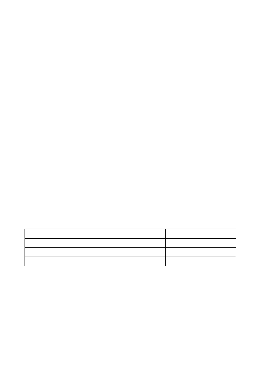
The following information is contained in these documents:
Information Document Type
Setup and installation of the Disconnect Unit Installation Guide
Unpacking, transporting and preparing the Disconnect Unit Unpacking manual
Disconnect Unit circuit diagram Circuit diagrams
Additional information is available at www.SMA-America.com.
Nomenclature
In this document, the Disconnect Unit for Sunny Central 250U/500U/500HE-US/CA and Sunny
Central CP are hereinafter referred to as the Disconnect Unit.
In this document, SMA America Production, LLC, and SMA Solar Technology Canada Inc. are
hereinafter referred to as SMA.
Unpacking DISU_SCUS-AP-eng-IUS110911 9
Page 10
Scope of Supply SMA America, LLC
2Scope of Supply
The Disconnect Unit is supplied in a box. This box contains the Disconnect Unit, the lid for the
Disconnect Unit and an accessories kit.
Ch eck the sco pe o f su ppl y fo r comple ten ess and for any ext ern al d ama ge. Ple ase con tac t yo ur d eal er
if the scope of supply is not complete or you find any damage.
The scope of supply is listed in this chapter.
Accessories Kit
The accessories kit is packed in a box. The box is called Accessories.
Supplied Components
Number Description
1 TX screwdriver T25
1 TX screwdriver T30
1 Warning sticker SC-US positive/negative grounding
1 Disconnect Unit Sunny Central US Installation Guide
1 Circuit diagram for DU-SC-US, EN
10 DISU_SCUS-AP-eng-IUS110911 Unpacking
Page 11

SMA America, LLC Storage
/05*$&
/05*$&
3Storage
Damage to property caused by penetrating moisture!
Damage to electrical component parts caused by penetrating moisture.
• The Disconnect Unit must be closed during storage.
• Storage for six months or more permissible in dry locations only.
• Do not store the Disconnect Unit in the transport packaging for longer than six months.
Damage to property caused by improper storage!
Improper storage conditions may damage the Disconnect Unit.
• The foundation must be suitable for the weight of the Disconnect Unit of 1 477 lbs. (685 kg).
The foundation may only deviate from a level of 0.25 %.
• Only store the Disconnect Unit at temperatures between − 40 °F ... +140 °F
( − 40 °C ... +60 °C).
Ensure function in the case of longer storage times
If the Disconnect Unit is stored for longer than one year, check the functionality of the
Disconnect Unit every 12 months. Move all switches to the "ON" position and the "OFF"
position ten times. This guarantees the function of the switches.
Unpacking DISU_SCUS-AP-eng-IUS110911 11
Page 12

Transport Packaging SMA America, LLC
A
BC
4 Transport Packaging
4.1 Transport Packaging and Center of Gravity
The front and back walls of the transport packaging are marked with a symbol for the center of
gravity. The center of gravity of the transport packaging is not in the middle. The symbol for the center
of gravity shows the position of the centre of gravity.
Figure1:Center of gravity indication
Center of Gravity of the Disconnect Unit for Sunny Central 250U/500U
All dimensions for the center of gravity indication relate to the bottom left corner of the back wall.
Horizontal (B) 3 5⁄16 ft. (1 013 mm)
Vertical (A) 3 3⁄
Depth (C) 1
12 DISU_SCUS-AP-eng-IUS110911 Unpacking
ft. (971 mm)
16
7
⁄8 ft. (570 mm)
Page 13

SMA America, LLC Transport Packaging
Center of Gravity of the Disconnect Unit for Sunny Central CP/500HE-US without
AC Switch:
All dimensions for the center of gravity indication relate to the bottom left corner of the back wall.
Horizontal (B) 3
Vertical (A) 3
5
⁄
ft. (1 010 mm)
16
3
⁄4 ft. (1 151 mm)
Depth (C) 1 5⁄8 ft. (494 mm)
Center of Gravity of the Disconnect Unit for Sunny Central CP/500HE-US with AC
Switch:
All dimensions for the center of gravity indication relate to the bottom left corner of the back wall.
Horizontal (B) 3 23⁄
Vertical (A) 3 43⁄
Depth (C) 1 ft. 9
ft. (1 023 mm)
64
ft. (1 119mm)
64
1
⁄2 in. (544 mm)
Unpacking DISU_SCUS-AP-eng-IUS110911 13
Page 14

Transport Packaging SMA America, LLC
4.2 Symbols on the Transport Packaging
The following symbols are applied to the transport packaging:
Symbol Explanation
Transport the transport packaging with this side up.
The contents of the transport packaging are fragile.
Do not use sharp tools when opening the transport packaging.
Do not place anything on top of the transport packaging.
Center of gravity of the transport packaging.
4.3 Technical Data for the Transport Packaging
Technical Data for the Disconnect Unit for Sunny Central 250U/500U
Weight (approximate) 1 150 lbs. (522 kg)
Width x height x depth 6 ft. x 6
Technical Data for the Disconnect Unit for Sunny Central CP/500HE-US
Weight (approximate) 1 510 lbs. (685 kg)
Width x height x depth 6 ft. x 7 in. x 3 ft. 4 in. x 8
14 DISU_SCUS-AP-eng-IUS110911 Unpacking
1
⁄2 ft. x 3 ft. 8 21⁄64 in. (1 829 mm x 1 981 mm x 1 130 mm)
21
⁄64in. (1 829 mm x 2 235 mm x 1 130 mm)
Page 15

SMA America, LLC Transporting the Packaged Disconnect Unit
8"3/*/(
5 Transporting the Packaged Disconnect Unit
You can transport the packaged Disconnect Unit using a forklift truck.
Danger of crushing caused by tipping package!
If insufficiently secured, the package can fall off the pallet.
• Only transport the package as described in this manual.
• Take note of the centre of gravity marking on the transport packaging.
• Means of transport must be designed for the weight of the package.
• Do not tip package over during transport.
• Transport the package only if sufficiently secured.
• Keep a safe distance from the package at all times during transport.
1. Drive forklift truck under the transport packaging at the center of gravity marking.
2. Secure the package against tipping, for example using lashing straps.
3. Raise the package slightly.
4. Transport the package.
Unpacking DISU_SCUS-AP-eng-IUS110911 15
Page 16

Unpacking the Disconnect Unit SMA America, LLC
/05*$&
6 Unpacking the Disconnect Unit
6.1 Removing the Film
The Disconnect Unit is packed using a protective film. This film is affixed to the pallet. Remove this film
as described in this section.
Damage to property caused by sharp objects!
When cutting through the film with a sharp object you could damage the enclosure of the
Disconnect Unit.
• Only cut through the film close to the pallet.
• Observe the correct distance from the enclosure.
1. Cut through film close to the pallet.
2. Pull film off the Disconnect Unit upward.
16 DISU_SCUS-AP-eng-IUS110911 Unpacking
Page 17

SMA America, LLC Unpacking the Disconnect Unit
$"65*0/
8"3/*/(
6.2 Removing the Lashing Straps
The Disconnect Unit box is secured to the pallet using lashing straps to prevent tipping during
transport.
Risk of being cut by rebounding lashing straps!
The lashing straps are under tension and spring back when removed.
• Wear personal protective equipment.
• Keep a safe distance from the lashing straps.
1. Cut through lashing straps with a knife.
2. Remove the lashing straps.
Danger of crushing caused by tipping package!
If insufficiently secured, the package can fall off the pallet.
• Take note of the centre of gravity marking on the transport packaging.
• All means of transport used must be designed for the weight of the package of 1 510 lbs.
(685 kg).
• Do not tip package over during transport.
• Do not transport the package unless sufficiently secured.
• Keep a safe distance from the package at all times during transport.
Unpacking DISU_SCUS-AP-eng-IUS110911 17
Page 18

Unpacking the Disconnect Unit SMA America, LLC
$"65*0/
6.3 Removing the Clamping Bands
The individual box components of the Disconnect Unit are affixed with clamping bands.
Risk of being cut by rebounding clamping bands!
The clamping bands are under tension and spring back when removed.
• Wear personal protective equipment.
• Keep a safe distance from the clamping bands.
1. Cut through clamping bands with a knife.
2. Remove the clamping bands.
6.4 Removing the Box Components
1. Remove lid of box.
18 DISU_SCUS-AP-eng-IUS110911 Unpacking
Page 19

SMA America, LLC Unpacking the Disconnect Unit
2. Remove wooden frame and squared timber.
3. Open the clamping fastener by pulling the strap on
the left-hand side.
4. Remove clamping fastener from box.
5. Remove walls of the box.
– Remove front wall of the box.
– Remove back wall of the box.
Unpacking DISU_SCUS-AP-eng-IUS110911 19
Page 20

Unpacking the Disconnect Unit SMA America, LLC
6. Remove boxes from the side. The lid and the
accessories kit are found in the lower box. The upper
box is packaging material.
7. Remove the box cover.
8. Unpack lid.
9. Remove accessories kit.
10. Open accessories kit.
20 DISU_SCUS-AP-eng-IUS110911 Unpacking
Page 21

SMA America, LLC Transporting the Disconnect Unit Without Packaging
8"3/*/(
7 Transporting the Disconnect Unit Without Packaging
7.1 Transporting the Disconnect Unit Using a Crane
Danger of crushing if raised or hovering Disconnect Unit tips over, falls or swings!
If the Disconnect Unit is raised and transported without due care or too quickly it may tip over or fall.
• Transport the Disconnect Unit as close to the ground as possible at all times.
• Use all suspension points for transportation.
• Avoid making fast and jerky movements with the crane.
• Keep a safe distance from the Disconnect Unit at all times during transport.
• All means of transport used must be designed for the weight of the Disconnect Unit of
1 510 lbs. (685 kg).
11. Position the crane hook with crane cables in the
center above the Disconnect Unit.
12. Connect the load hook of the crane cables to all four
crane eyes of the Disconnect Unit.
13. Raise the crane hook slowly until the crane cables are
tensed.
14. Ensure that all crane cables and load hooks are attached correctly.
15. Raise the Disconnect Unit slightly.
16. Transport the Disconnect Unit to the installation site.
Unpacking DISU_SCUS-AP-eng-IUS110911 21
Page 22

Transporting the Disconnect Unit Without Packaging SMA America, LLC
7.2 Transporting the Disconnect Unit Using a Forklift Truck
Removing the Kick Plates of the Disconnect Unit
Unscrew the kick plates to transport the Disconnect Unit using a forklift truck.
There are two kick plates at the front and two kick plates at the back of the Disconnect Unit.
1. Remove all eight screws of the two front kick plates.
2. Remove both front kick plates.
3. Remove all eight screws of the two rear kick plates.
22 DISU_SCUS-AP-eng-IUS110911 Unpacking
Page 23

SMA America, LLC Transporting the Disconnect Unit Without Packaging
8"3/*/(
4. Remove both rear kick plates.
Transporting the Disconnect Unit
Danger of crushing caused by tipping of the Disconnect Unit!
If insufficiently secured, the Disconnect Unit can tip over.
• Only transport the Disconnect Unit as described in this manual.
• Observe the center of gravity of the Disconnect Unit.
• All means of transport used must be designed for the weight of the Disconnect Unit of
1 510 lbs. (685 kg).
• Do not tip Disconnect Unit over during transport.
• Transport the Disconnect Unit only if sufficiently secured.
• Keep a safe distance from the Disconnect Unit at all times during transport.
1. Drive the forklift truck under t he D isc onn ect Unit at the
front or back.
2. Secure Disconnect Unit against tipping, for example using lashing straps.
3. Raise the Disconnect Unit slightly.
4. Transport the Disconnect Unit to the installation site.
Unpacking DISU_SCUS-AP-eng-IUS110911 23
Page 24

Transporting the Disconnect Unit Without Packaging SMA America, LLC
Install the Kick Plates of the Disconnect Unit
After transporting the Disconnect Unit, replace the kick plates.
1. Align both front kick plates to the Disconnect Unit and
place all eight screws in the holes.
2. Tighten all eight screws of the two front kick plates
with a torque of 44 in-lbs. (5 Nm).
3. Align both re ar kic k plat es to the Disconnect Unit and
place all eight screws in the holes.
4. Tighten all eight screws of the two rear kick plates
with a torque of 44 in-lbs. (5 Nm).
24 DISU_SCUS-AP-eng-IUS110911 Unpacking
Page 25

SMA America, LLC Preparing the Disconnect Unit for Installation
$"65*0/
Off
On
8 Preparing the Disconnect Unit for Installation
8.1 Opening the Disconnect Unit
Note the grounding strap on the front plate
At the bottom left corner of the front plate, a grounding strap is fitted and connected to the
Disconnect Unit. Do not damage the grounding strap when opening the Disconnect Unit.
Danger of crushing caused by heavy front plate!
When removing the front plate, there is a danger of crushing between the Disconnect Unit and the
front plate.
• Note the weight of the front plate of 110 lbs. (50 kg).
• Move the front plate of the Disconnect Unit with at least two persons.
• Ensure that one person is holding the front plate of the enclosure at all times when the other
person is working on it.
• Wear personal protective equipment.
1. Turn all switches of the Disconnect Unit to the right
into the "On" position. Push or pull the switches hard
to move them.
2. Release the three screws on the handles on the lefthand side of the front plate.
Unpacking DISU_SCUS-AP-eng-IUS110911 25
Page 26

Preparing the Disconnect Unit for Installation SMA America, LLC
On
Off
3. Tu rn al l sw itc hes on t he D isc onn ect Uni t to t he l eft int o
the "Off" position. Push or pull the switches hard to
move them.
4. Release all screws with the exception of the screws in
the four corners of the front plate.
5. Hold the front plate of the Disconnect Unit and
release the last four screws.
6. Pull the bottom edge of the front plate of the
enclosure approximately 6 in. (150 mm) to the front.
26 DISU_SCUS-AP-eng-IUS110911 Unpacking
Page 27

SMA America, LLC Preparing the Disconnect Unit for Installation
7. Pull the front plate of the enclosure upwards and
unhook.
8. Pull the front plate forwards by around 8 in.
(200 mm) and hold with two hands.
9. Unscrew grounding strap at the bottom left corner
of the front plate.
10. Remove front plate.
Unpacking DISU_SCUS-AP-eng-IUS110911 27
Page 28

Preparing the Disconnect Unit for Installation SMA America, LLC
$"65*0/
DISCO
N
N
ECT UNIT
SMA
8.2 Mounting the Lid
Danger of crushing between the lid and the Disconnect Unit!
• Note the weight of the lid of 37.5 lbs. (17 kg).
• Install the lid of the Disconnect Unit with at least two persons.
• Make sure that one person always hold the lid while the other person performs work at it.
Screws for Installing the Lid
Screws to affix the lid are found in a bag attached to the lid. Remove the bag and unpack the
screws before affixing the lid.
Note the grounding strap on the lid
A grounding strap is installed on the lid. The free end is affixed to the lid. Remove the adhesive
strips before installing the lid. Connect the grounding strip to the Disconnect Unit as described
below.
1. Clean lid.
2. Lay the lid on the Disconnect Unit, slightly to one side.
3. Screw grounding strap to the Disconnect Unit with
contact washer, washer, split lock washer and nut
with a torque of 71 in-lbs. (8 Nm).
4. Push the lid forwards from the back beneath the
straps.
28 DISU_SCUS-AP-eng-IUS110911 Unpacking
Page 29

SMA America, LLC Preparing the Disconnect Unit for Installation
DISCONNECT UNIT
SMA
DISCONNECT UNIT
SM
5. Align the lid flush with the sides and back of the
Disconnect Unit. Holes in the front of the lid must be
positioned to fit over the threads of the Disconnect
Unit.
6. Install the lid on the Disconnect Unit using the screws
provided.
7. Tighten screws with a torque of 18 in-lbs. (2 Nm).
8.3 Closing the Disconnect Unit
Fully Installing the Disconnect Unit
If you are fully installing the Disconnect Unit in accordance with the Installation Guide, you will
save time because the Disconnect Unit is already open. If the installation takes place later or at
a different location, close the Disconnect Unit as described in this chapter.
Note before closing the Disconnect Unit
• The handles on the front plate of the enclosure must be put into the "Off" position so that
the shafts can be engaged.
• The two hooks for the front plate of the enclosure must be correctly positioned. The two
hooks are moveable and must be arranged 11
(300 mm … 400 mm) from the sides.
3
⁄4in. … 1 ft. 33⁄4in.
Figure2:Position of the hooks for connecting the front plate.
Unpacking DISU_SCUS-AP-eng-IUS110911 29
Page 30

Preparing the Disconnect Unit for Installation SMA America, LLC
$"65*0/
D
IS
CO
N
N
EC
T U
N
IT
SM
A
Danger of crushing caused by heavy front plate!
• Note the weight of the front plate 110 lbs. (50 kg).
• Move the front plate of the Disconnect Unit with at least two persons.
• Ensure that one person is holding the front plate of the enclosure at all times when the other
person is working on it.
1. Screw the grounding strap in the bottom left corner
of the Disconnect Unit to the front plate of the
enclosure. Tighten screw with a torque of 71 in-lbs.
(8 Nm).
2. Tip the front plate over with two persons so that the
upper edge is pointing towards the Disconnect Unit.
Hook the front plate of the enclosure onto the two
hooks on the front of the Disconnect Unit.
3. Press the lower edge of the front plate of the
enclosure onto the Disconnect Unit.
4. For each of the switch handles on the front of the front plate: Shake the handles gently a few
times so that the switch shaft engages with the handle.
30 DISU_SCUS-AP-eng-IUS110911 Unpacking
Page 31

SMA America, LLC Preparing the Disconnect Unit for Installation
5. Fit the front plate of the enclosure to the Disconnect
Unit with four screws and four sealing washers at its
four corners. Tighten the screws so that they are handtight (the front plate of the enclosure can still be
moved).
6. 11 accessible holes are left without screws on the
front plate. The three holes behind the left handles
are not reachable yet. Insert one screw with sealing
washer in each of the 11 holes. Fasten the screws
hand-tight.
7. Ensure that the front plate of the enclosure is aligned at the edg es o f th e Di sco nne ct U nit . Ti ght en
all screws with a torque of 44 in-lbs. (5 Nm).
8. Ensure that all switches are functioning correctly. Switch all switches into the "On" position and
then back into the "Off" position.
The switches function properly if there is no clearance of the shafts and the switches make a
clear switching noise. Readjust if necessary.
9. When all switches are functioning correctly: Switch
all switches into the "On" position and insert three
screws with sealing washers into the holes on the
handles on the left-hand side. Tighten screws with a
torque of 44 in-lbs. (5 Nm).
10. Switch all switches into the "Off" position.
Unpacking DISU_SCUS-AP-eng-IUS110911 31
Page 32

Preparing the Disconnect Unit for Installation SMA America, LLC
11. For the Disconnect Unit for Sunny Central 500HEUS/CA/CP: Make sure that the grounding strap at
the clamp of the AC switch is correctly connected to
the flap and that it is not jammed between enclosure
and flap. Close the flap after check.
32 DISU_SCUS-AP-eng-IUS110911 Unpacking
Page 33

SMA America, LLC Contact
9Contact
If you have technical problems concerning our products, please contact our Serviceline. We require
the following information in order to provide you with the necessary assistance:
• Device type
•Serial number
SMA America, LLC
6020 West Oaks Blvd, Ste 300
Rocklin, CA 95765
Tel. +1 916 625 0870
Tel. +1 877-MY SMA TECH
Tel. +1 877 697 6283 (Toll free, available for USA, Canada, and Puerto Rico)
Fax +1 916 625 0871
Service@SMA-America.com
www.SMA-America.com
SMA Solar Technology Canada Inc.
2425 Matheson Blvd. E
8th Floor
Mississauga, ON L4W 5K5
Canada
Unpacking DISU_SCUS-AP-eng-IUS110911 33
Page 34

Page 35

Page 36

SMA America, LLC
4.""NFSJDB--$
XXXSMAANFSJDBDPN
36 DISU_SCUS-AP-eng-IUS110911 Unpacking
 Loading...