

SMA DC-CMB-U10-16,DC-CMB-U10-32,DC-CMB-U10-24 Installation Manual
Installation Manual - Manuale di installazione - Manual de Instalare
SMA STRING-COMBINER
DC-CMB-U10-16 / DC-CMB-U10-24 / DC-CMB-U10-32
DC-CMB-IA-U10-xx-en | 910.400.182C | Version 1.0
ENGLISH
ITALIANO
ROMANIAN

Legal Provisions SMA Solar Technology AG
Legal Provisions
The information contained in this document is the property of SMA Solar Technology AG. Publishing its content, either
partially or in full, requires the written permission of SMA Solar Technology AG. Any internal company copying of the
document for the purposes of evaluating the product or its correct implementation is allowed and does not require
permission.
SMA Warranty
You can download the current warranty conditions from the Internet at www.SMA-Solar.com.
Trademarks
All trademarks are recognized, even if not explicitly identified as such. A lack of identification does not mean that a
product or symbol is not trademarked.
The BLUETOOTH® word mark and logos are registered trademarks owned by Bluetooth SIG, Inc. and any use of these
marks by SMA Solar Technology AG is under license.
Modbus® is a registered trademark of Schneider Electric and is licensed by the Modbus Organization, Inc.
QR Code is a registered trademark of DENSO WAVE INCORPORATED.
Phillips® and Pozidriv® are registered trademarks of Phillips Screw Company.
Torx® is a registered trademark of Acument Global Technologies, Inc.
SMA Solar Technology AG
Sonnenallee 1
34266 Niestetal
Germany
Tel. +49 561 9522-0
Fax +49 561 9522-100
www.SMA.de
E-mail: info@SMA.de
© 2004 to 2014 SMA Solar Technology AG. All rights reserved.
2 Installation Manual
DC-CMB-IA-U10-xx-en

SMA Solar Technology AG
2 Table of Contents
Table of Contents
1 Information on this Document ................................................................................................................ 4
2 Safety ....................................................................................................................................................... 5
2.1 Intended Use ................................................................................................................................................................................................... 5
2.2 Skills of Qualified Persons .......................................................................................................................................................................... 5
2.3 Instructions and Warnings .......................................................................................................................................................................... 5
2.4 Position and securing ................................................................................................................................................................................... 6
2.5 Safety Precautions ........................................................................................................................................................................................ 7
3 Scope of Delivery .................................................................................................................................. 9
4 Product Description ............................................................................................................................... 10
4.1 Combiner Box DC-CMB-U10-16/24/32 ..................................................................................................................................................10
4.2 Type Label ...................................................................................................................................................................................................... 10
4.3 DC Load-Break Switch ................................................................................................................................................................................ 11
4.4 Suggestion on fuse choosing ....................................................................................................................................................................11
4.5 String Fuses .................................................................................................................................................................................................... 12
4.6 Overvoltage Protection .............................................................................................................................................................................. 12
5 Assembly ................................................................................................................................................ 13
5.1 Wall Mounting ................................................................................................................................................................................................ 13
5.1.2 Mounting the Combiner Box .................................................................................................................................................................................... 14
5.2 Drilling Template for Mounting ................................................................................................................................................................ 17
6 Electrical Connection ............................................................................................................................. 18
6.1 Connection Instructions ............................................................................................................................................................................... 18
6.2 Safety during Electrical Connection .......................................................................................................................................................19
6.3 Inserting the Cables into the Switch Cabinet .....................................................................................................................................19
6.3.1 DC-CMB-U10-16 ........................................................................................................................................................................................................... 19
6.3.2 Overview of the Connection Area DC-CMB-U10-16 ...................................................................................................................................... 20
6.3.3 Inserting the Cables into the Switch Cabinet DC-CMB-U10-24 ................................................................................................................... 21
6.3.4 Overview of the Connection Area DC-CMB-U10-24 ..................................................................................................................................... 22
6.3.5 Inserting the Cables into the Switch Cabinet DC-CMB-U10-32 .................................................................................................................. 23
6.3.6 Overview of the Connection Area DC-CMB-U10-32 ..................................................................................................................................... 24
6.4 Leading the Cables through the Cable Glands with Sealing Ring Cut-Outs............................................................................25
6.5 Connecting the String Cables .................................................................................................................................................................25
6.5.1 Cable requirements: .................................................................................................................................................................................................. 25
6.6 Connecting the DC Main Cables ...........................................................................................................................................................25
6.6.1 Cable Requirements .................................................................................................................................................................................................. 25
6.7 Assembly of the Connection .................................................................................................................................................................. 26
6.7.1 Two Terminal Lugs ................................................................................................................................................................................................... 26
6.7.2 One Terminal Lug ...................................................................................................................................................................................................... 26
6.7.3 Connection procedure: ............................................................................................................................................................................................ 27
6.8 Connecting the Grounding Cable .......................................................................................................................................................... 27
7 Commissioning ......................................................................................................................................28
7.1 Safety during Commissioning ................................................................................................................................................................... 28
7.2 Commissioning the Combiner Box ......................................................................................................................................................... 28
7.2.1 Requirements for Commissioning .......................................................................................................................................................................... 28
7.3 Voltage Check – Measuring Procedure .................................................................................................................................................. 28
8 Maintenance ......................................................................................................................................... 30
8.1 Periodic Maintenance .................................................................................................................................................................................. 30
8.2 Extraordinary Maintenance ...................................................................................................................................................................... 30
9 Disconnecting ......................................................................................................................................... 31
10 Decommissioning ................................................................................................................................32
10.1 Disassembling the Combiner Box .......................................................................................................................................................... 32
10.2 Disposing of the Combiner Box ............................................................................................................................................................ 32
11 Technical Data ......................................................................................................................................33
12 Contact .................................................................................................................................................34
Installation Manual
DC-CMB-IA-U10-xx-en
3
1
Information on this document
SMA Solar Technology AG
1 Information on this Document
Validity
This document is valid for the following device types:
• DC-CMB-U10-16
• DC-CMB-U10-24
• DC-CMB-U10-32
Target Group
This document is intended for qualified persons. Only persons with the appropriate skills are allowed to perform the
activities described in this document (see Section 2.2 “Skills of Qualified Persons”, page 5).
Additional Information
Links to additional information can be found at www.SMA-Solar.com.
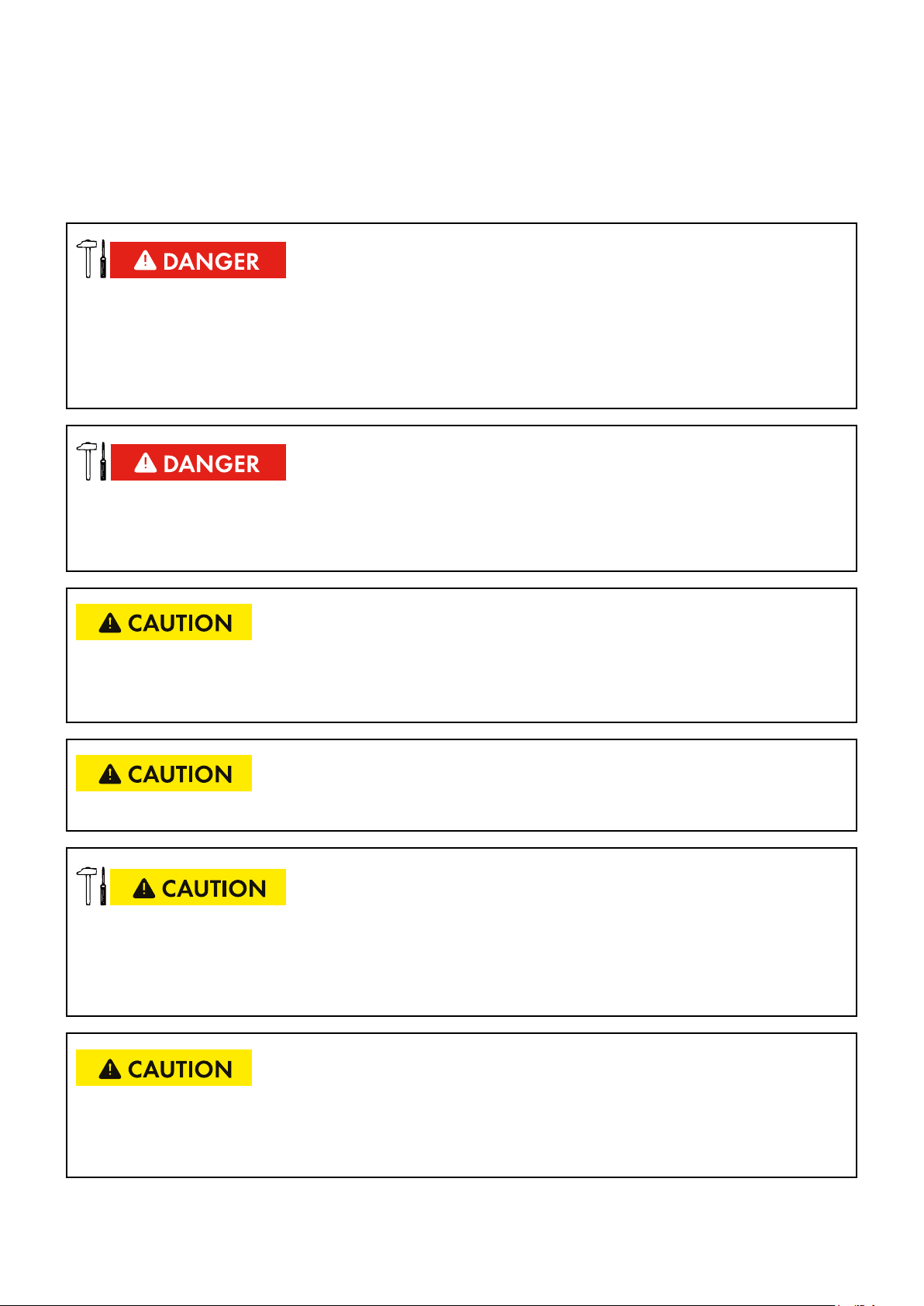
Symbols
Symbol Explanation
Indicates a hazardous situation which, if not avoided, will result in death or serious injury
Indicates a hazardous situation which, if not avoided, can result in death or serious injury
Indicates a hazardous situation which, if not avoided, can result inminoror moderate injury
Indicates a situation which, if not avoided, can result in property damage
o
R
Nomenclature
This document is relevant for the SMA String-Combiner Box for Utility Power System.
They are jointly referred to in the following as “Combiner Box”.
Indicates a requirement for meeting a specific goal
Desired result
Packaging instructions
Describes the installation procedure of the product
Describes the use of the product and its graphic display
Contains useful information for disposing of the product
4
DC-CMB-IA-U10-xx-en
Installation Manual
SMA Solar Technology AG
2 Safety
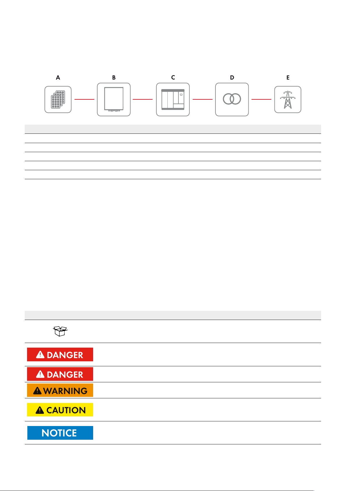
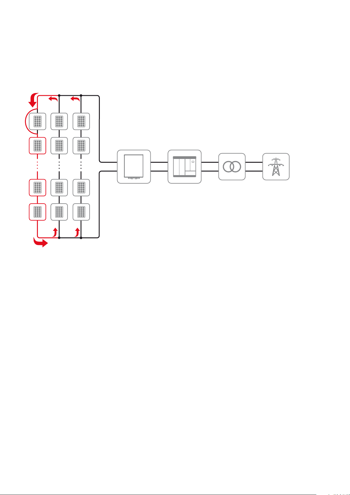
2.1 Intended Use
Position Explanation
A
B
C
D
E
PV array
Combiner Box
Sunny Central
Transformer
Utility grid
2 Safety
2.2 Skills of Qualified Persons
The tasks described in this document must be performed by qualified persons only. Qualified persons must have the
following skills:
• Knowledge of how the device works and is operated
• Training in how to deal with the dangers and risks associated with installing and using electrical devices and systems
• Training in the installation and commissioning of electrical devices
• Knowledge of all applicable standards and directives
• Knowledge of and compliance with this document and all safety precautions
2.3 Instructions and Warnings
Failure to follow these instructions may have serious consequences, such as the destruction of the device, personal injury or
death due to electric shock. Therefore, the following safety instructions must be read and understood prior to installation and
use of the Combiner Box. For any clarifications or additional information, contact the SMA technical service.
Symbol Explanation
Once the product has been removed from its original packaging, visually inspect for damage that may have occurred during shipment. If damage is found, contact the distributor or
manufacturer.
This product must only be used for the purpose for which it has been designed. Any other
use is considered improper and therefore dangerous. The manufacturer is not liable for
possible damage caused by improper, incorrect or unreasonable use.
SMA holds itself responsible only for the product in its original configuration.
SMA declines all responsibility for consequences deriving from non-original spare parts.
Any intervention that alters the structure or the operating cycle of the product must be carried out or authorized by SMA Solar Technology AG.
This manual is an integral and essential part of the product.
Carefully read the recommendations contained in it since they provide important information on safe use and maintenance.
SMA may make technical changes in this manual and to the product at any time without
notice. In case of typing errors or other types of errors, the corrections will be included in
the new versions of the manual.
Installation Manual
DC-CMB-IA-U10-xx-en
5
2 Safety
SMA Solar Technology AG
2.4 Position and securing
Failure to follow these instructions may have serious consequences, such as the destruction of the device, personal injury or
death due to electric shock. Therefore, the following safety instructions must be read and understood prior to installation and
use of the Combiner Box. For any clarifications or additional information, contact the SMA Solar Technology AG.
Symbol Explanation
The enclosure is made of fibreglass with protection rating of IP54.
If positioning in a closed environment, make sure the area is ventilated and allows regular
recirculation of air. If installing in an open environment, position the enclosure in an area
that is constantly shaded and protected from exposure to direct sunlight. These measures are
important for preventing unnecessary and excessive overheating, which prolonged in time
impairs the duration and operation of parts inserted inside, since the enclosure supports the
correct dissipation of heat developed by the energy coming from the strings at a maximum
temperature of 50°C (60°C with derating of 1%/K of max current).
The symbol indicates that the enclosure is constructed in such a way that it provides
protection against indirect contacts via complete insulation (EN 61439-2). For this purpose,
the electrical equipment must be correctly installed according to the instructions that
accompany the product and using the special accessories (screw cover caps, mounting
brackets).
Make sure the wall where the enclosure is to be mounted is suitable to support the weight.
The weight of these enclosure varies from 24 kg for the 16 string model to over 30 kg for
the model with 32 strings.
6
DC-CMB-IA-U10-xx-en
Installation Manual
SMA Solar Technology AG
2 Safety
2.5 Safety Precautions
This section contains safety precautions that must be observed at all times when working on or with the product.
To prevent personal injury and property damage and to ensure long-term operation of the product, read this section carefully and follow all safety precautions at all times.
Danger to life from electric shock due to live voltage
High voltages are present in the live components of the Combiner Box. Touching live components results in death
or serious injury due to electric shock.
• Wear personal protective equipment when working on the Combiner Box.
• Do not touch live components.
• Before performing any work, always disconnect the Combiner Box from voltage sources unless supply voltage is
absolutely necessary.
– Switch off the DC load-break switch in the Combiner Box.
– With power off, remove the DC fuses in the central inverter or main DC distribution box. Use the LV/HRC fuse
handle to do this.
– Only open the fuse holders when the Combiner Box is switched off.
• Ensure that the device cannot be reconnected.
• Ensure that no voltage is present.
• Ground and short-circuit.
• Cover or isolate any adjacent live components. Protective covers must always be mounted.
Danger to life from electric shock due to live DC cables
DC cables connected to PV modules that are exposed to sunlight carry live voltage. Touching live DC cables results in
death or serious injury.
• Prior to connecting the DC cables, ensure that the DC cables are voltage-free.
• Wear suitable personal protective equipment when working on the Combiner Box.
Danger to life from electric shock due to ground fault
In the event of a ground fault, grounded PV systems can still be live. Touching system components that have not been
properly grounded results in death or serious injuries from electric shock.
• Before working on the PV system, ensure that no ground fault is present.
• Wear suitable personal protective equipment for all work on the device.
Danger to life from electric shock if the Combiner Box is damaged
If the Combiner Box is damaged, dangerous situations may arise during operation that result in death or serious
injury from electric shock.
• Only use the Combiner Box when it is in a technically faultless condition and safe to operate.
• Regularly check the Combiner Box for visual damage.
• Make sure that all external safety equipment is freely accessible at all times.
• Make sure that all safety equipment is in good working order.
Installation Manual
DC-CMB-IA-U10-xx-en
7
2 Safety
Danger to life from electric shock if the Combiner Box is left unlocked
If the Combiner Box is unlocked, unauthorized persons will have access to components carrying lethal voltages.
Touching live components can result in death or serious injury due to electric shock.
SMA Solar Technology AG
• Always lock the Combiner Box.
• Remove the keys from the door locks.
• Keep the keys in a safe place.
Risk of fire due to failure to observe torque specifications on live bolted connections
Failure to follow the specified torques reduces the capacity of live bolted connections so that the contact resistances
increase. This can cause components to overheat and catch fire.
• Ensure that live bolted connections are always tightened with the exact torque specified in this document.
• When working on the device, use suitable tools only.
• Avoid repeated tightening of live bolted connections, as this may result in inadmissibly high torques.
Risk of burns due to hot components or devices
Some components of the Combiner Box can get very hot during operation. Touching these components can cause
burns.
• Observe the warnings on the components.
• During operation, do not touch any components or devices marked with such warnings.
• After disconnecting the PV system from voltage sources, wait until all hot components have cooled down sufficiently.
• Wear suitable personal protective equipment for all work on the device.
8
DC-CMB-IA-U10-xx-en
Installation Manual
SMA Solar Technology AG
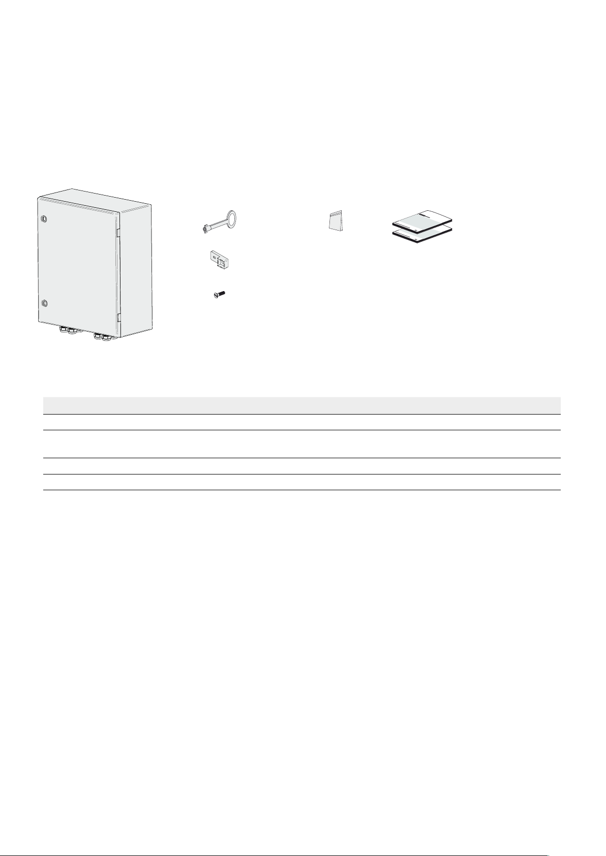
3 Scope of Delivery
3 Scope of Delivery
Check the scope of delivery for completeness and any externally visible damage. Contact your distributor if the scope of
delivery is incomplete or damaged.
DC-CMB-U10-16/24/32 for Wall Mounting
A B C D
Figure 2: Components included in the scope of delivery for wall mounting
Position Quantity Designation
A 1 DC-CMB-U10-16/24/32 Combiner Box
B 1 Combiner Box door key (1 pcs) / Wall mounting rail (4 pcs) / Screw for the wall
mounting rail (4 pcs)
C 1 Caps and reducing inserts kit
D 1 Installation manual, circuit diagram, test report, declaration of conformity
Installation Manual
DC-CMB-IA-U10-xx-en
9
4 Product Description
SMA Solar Technology AG
4 Product Description
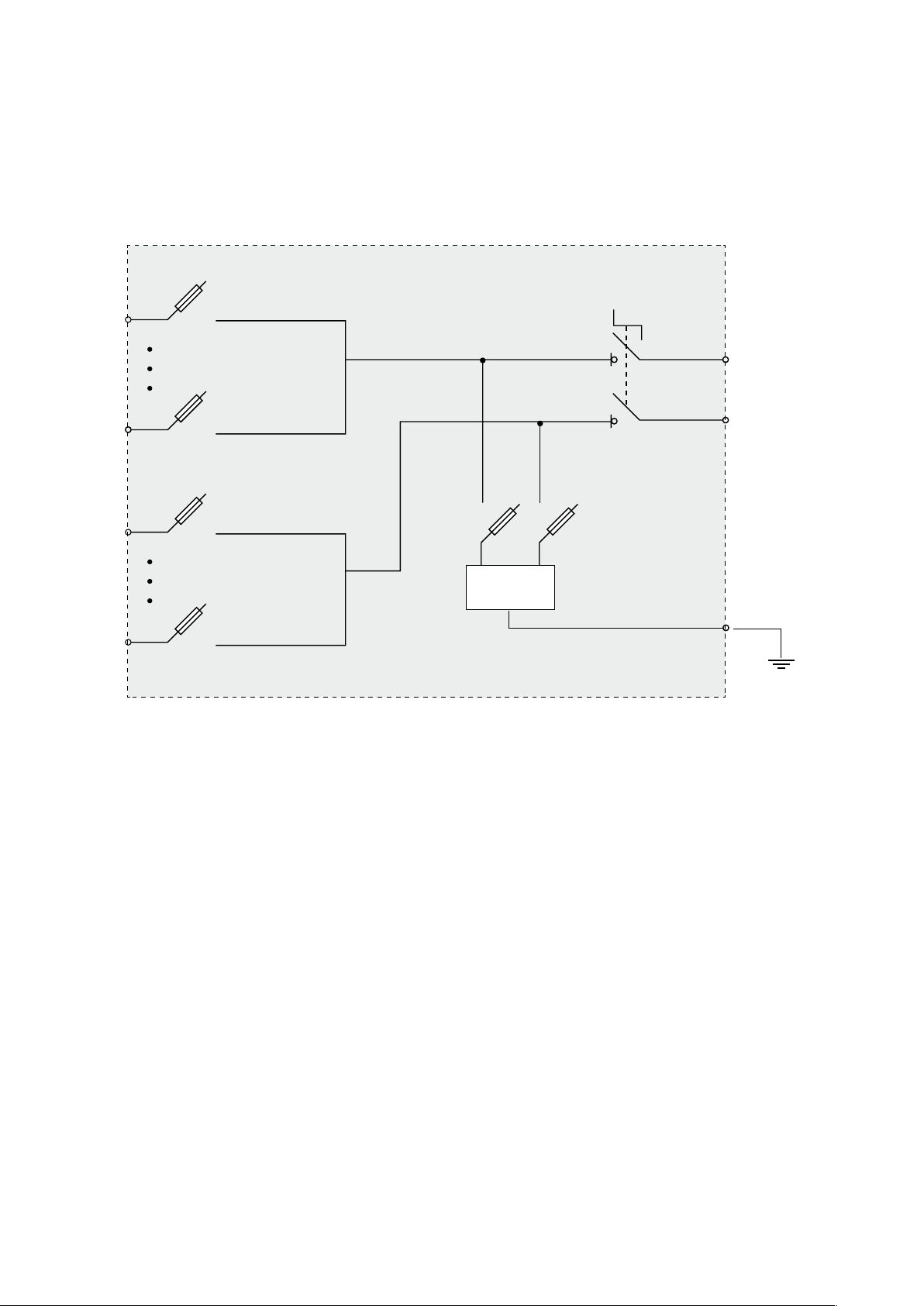
4.1 Combiner Box DC-CMB-U10-16/24/32
The DC-CMB-U10-16/24/32 Combiner Box is a PV array junction box to which several strings can be connected in
parallel.
FU1+
L +
FU (n)+
FUSPD +
FUSPD -
Q
0
L -
FU1 -
SPD
FU(n) -
n= 16 or 24 or 32
Figure 3: Block circuit diagram of the DC-CMB-U10-16/24/32 Combiner Box
The string fuses in the Combiner Box protect the PV modules of the strings from reverse currents.
4.2 Type Label
There is one type label attached to the Combiner Box.
The type label is located inside the right-hand door of the Combiner Box.
You will find the following information on the type label:
• Manufacturer
• Device type and option code
• Serial number
• Device-specific characteristics
You will require the information on the type label to use the product safely and when seeking customer support from the
SMA Service Line. The type label must remain permanently attached to the product.
10
DC-CMB-IA-U10-xx-en
Installation Manual
SMA Solar Technology AG
Symbols on the Type Label
Symbol Explanation
Danger to life due to high voltages
The product operates at high voltages. All work on the product must be carried out by
qualified persons only.
Risk of burns due to hot surfaces The product can get hot during operation. Avoid contact
during operation. Allow the product to cool down sufficiently before carrying out any work.
Wear personal protective equipment such as safety gloves.
Observe the documentation.
Observe all documentation supplied with the product.
CE marking
The product complies with the requirements of the applicable EU directives.
WEEE designation
Do not dispose of the product together with the household waste but in accordance with
the locally applicable disposal regulations for electronic waste.
4 Product Description
4.3 DC Load-Break Switch
The Combiner Box can be disconnected on the inverter side by means of a DC load-break switch. The use of the
DC load-break switch is only permissible if LV/HRC fuses with gPV characteristic are installed upstream in the inverter or
main DC distribution box.
4.4 Suggestion on fuse choosing
Derating Combiner Fuse
Ambiant temperature => Current derating
<= +40° reduction factor of 0.6
> +40° up to +55° reduction factor of 0.55
The following applies
NOM FUSE
I
≥ ISC_STC / Reduction factor
Installation Manual
DC-CMB-IA-U10-xx-en
11
4 Product Description
SMA Solar Technology AG
4.5 String Fuses
The string fuses protect the PV modules of a PV system from reverse currents. Only install string fuses supplied or approved
by SMA Solar Technology AG as accessories for Combiner Box.
Figure 4: Principle of reverse current
A reverse current can occur when different open-circuit voltages are applied to PV modules connected in parallel. In this
event, the reverse current can be much higher than the short-circuit current of the PV modules. The higher the reverse
current, the more the PV modules of the faulty string will heat up. Strong heat build-up can destroy the modules of the
faulty string.
A reverse current can be caused by the following:
• a short circuit in one or more modules
• a short circuit in one or more cells in a module
• a double ground fault in a module
• a double ground fault in the cabling
The string fuses trip when the string current is too high and protect the PV modules of the faulty string.
4.6 Overvoltage Protection
The Combiner Box is equipped with a surge arrester for overvoltage protection. The surge arrester protects the inverter
from transient overvoltages. In order to guarantee the overvoltage protection function, the surge arrester must be
connected to the external grounding.
12
DC-CMB-IA-U10-xx-en
Installation Manual
SMA Solar Technology AG
5 Assembly
5 Assembly
5.1 Wall Mounting
5.1.1 Selecting the Mounting Location
Fire hazard due to wrong choice of mounting location
Under fault conditions electric arcs may occur in the Sunny String-Monitor. Electric arcs can cause fires if the Sunny
String-Monitor is mounted on flammable materials.
• Do not mount the SMA String-Combiner on flammable construction materials.
• Do not mount the SMA String-Combiner near highly flammable materials.
• Do not mount the SMA String-Combiner in potentially explosive atmospheres.
Requirements for the mounting location:
o The mounting location must not be in a living or office area.
o The mounting location must not block any escape routes.
o The mounting location must be freely and safely accessible at all times without the necessity for any auxiliary
equipment (such as scaffolding or lifting platforms). Non-fulfillment of these criteria may restrict servicing.
o The mounting location must be suitable for the weight and dimensions of the Combiner Box.
o The mounting location must not be exposed to direct solar irradiation.
Requirements for mounting:
o Mount the Combiner Box in such a way that the connection area is facing downwards.
o Do not mount the Combiner Box in a horizontal or inclined position.
o An external cable support rail must be provided.
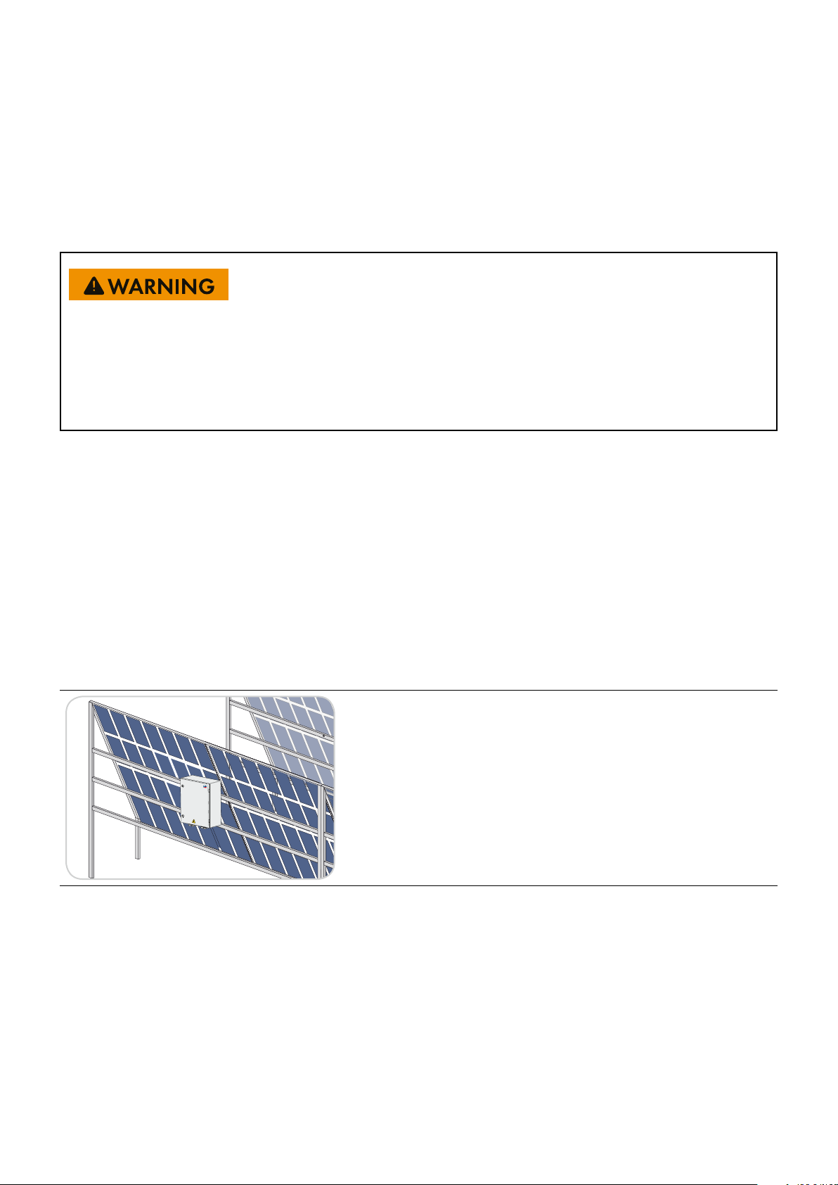
Example: Mounting the Combiner Box
If the PV array is mounted on a free-standing structure, the
Combiner Box can be fixed to this structure in a shaded
position. Make sure that the Combiner Box enclosure is not
mounted in the path of rainwater flowing off the module
surface.
Installation Manual
DC-CMB-IA-U10-xx-en
13
5 Assembly
SMA Solar Technology AG
5.1.2 Mounting the Combiner Box
Danger of crushing if the Combiner Box is dropped
• When mounting the Combiner Box, take the weight of up to 35 kg into account.
• Two people are needed to mount the Combiner Box.
• Installer should use personal protective equipment.
Damage to cable glands and plug connections due to improper transport and installation
The cable glands and plug connections protrude from the enclosure.
• When transporting and mounting the Combiner Box, ensure that the cable glands and plug connections are not
damaged.
Additionally required mounting material (not included in the scope of delivery):
• Four M8 screws. Take wall properties into account when choosing the screw type.
• Four washers
• If necessary, four screw anchors. Take wall properties into account when choosing the screw anchor type.
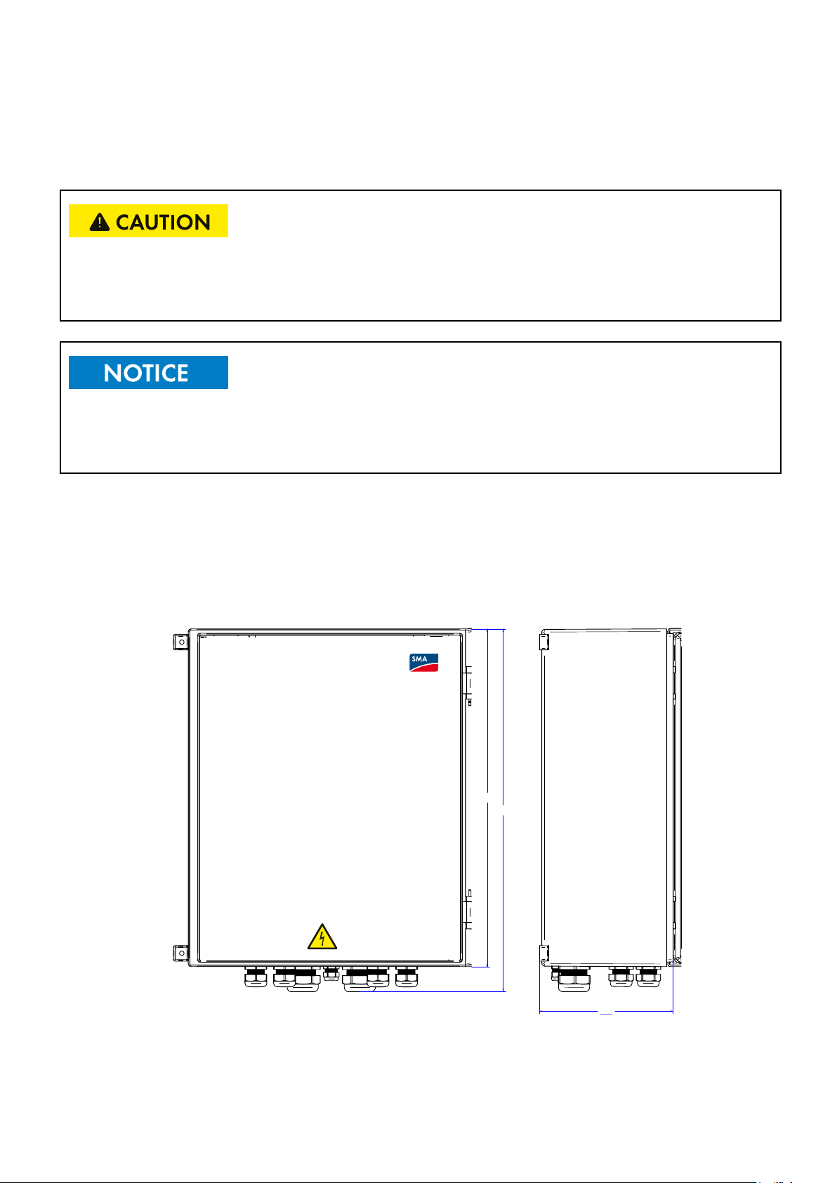
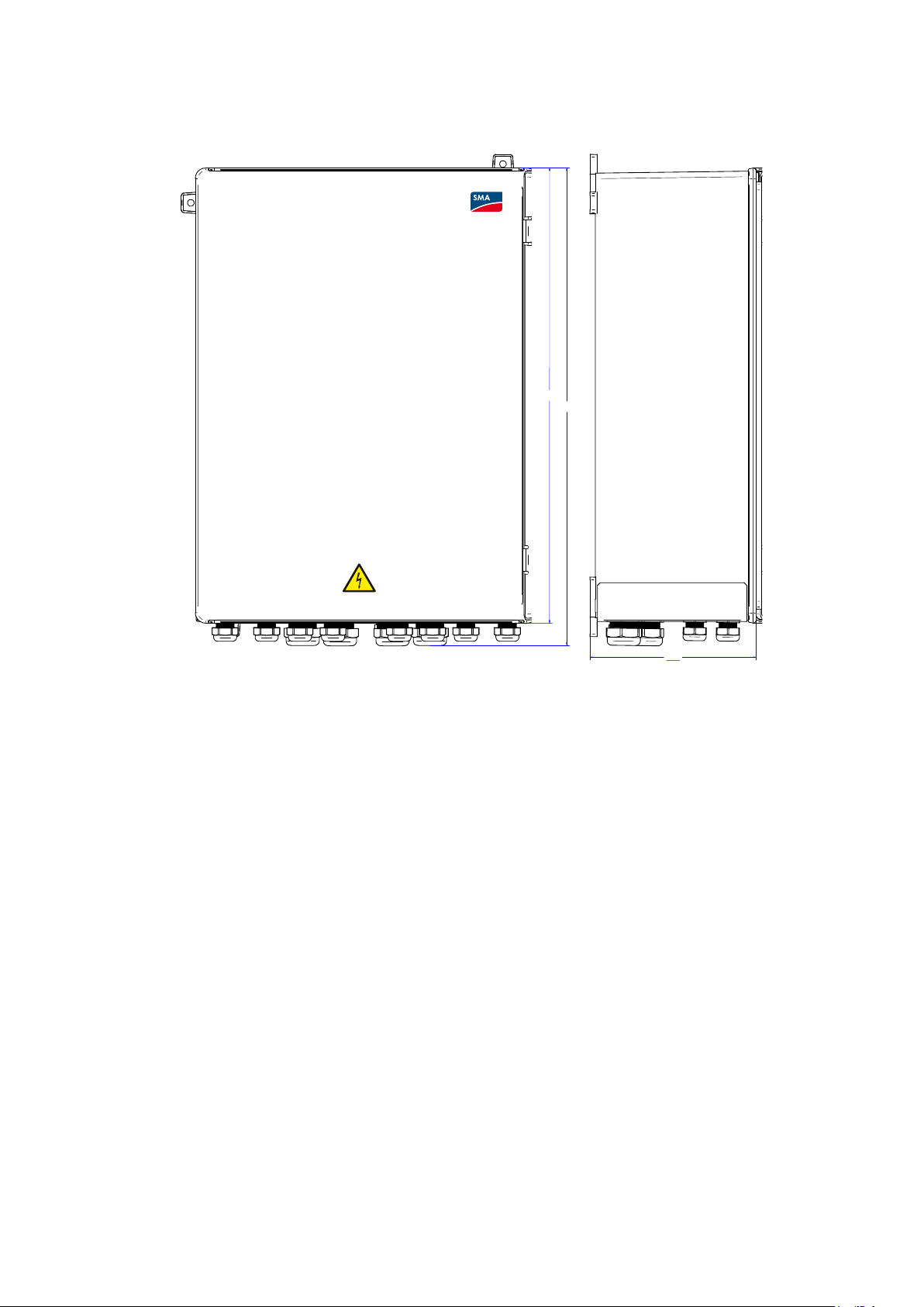
650
700
Figure 6a: Dimensions of the Combiner Box 16/24
14
DC-CMB-IA-U10-xx-en
270
Installation Manual
SMA Solar Technology AG
822
5 Assembly
862
325
Figure 6b: Dimensions of the Combiner Box 32
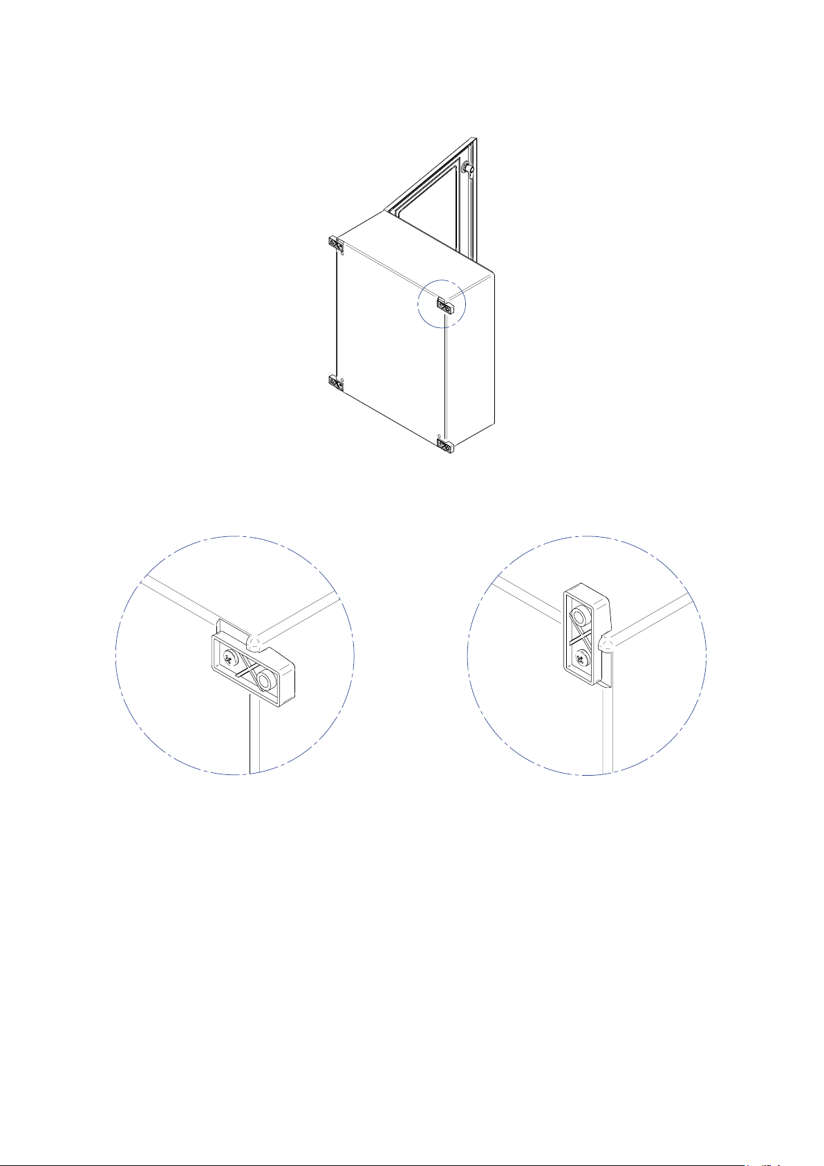
Procedure:
1. Mark the position of the drill holes on the wall or stand.
2. Drill holes at the marked positions.
3. If necessary, insert the screw anchors. Attach the two mounting rails to the Combiner Box with the screws supplied
(torque: 15 Nm).
4. Fasten the Combiner Box to the wall or stand using suitable screws and washers.
5. Ensure that the Combiner Box is securely fixed.
Installation Manual
DC-CMB-IA-U10-xx-en
15
5 Assembly
SMA Solar Technology AG
A
Horizontal mounting Vertical mounting
B
A
16
DC-CMB-IA-U10-xx-en
Installation Manual
SMA Solar Technology AG
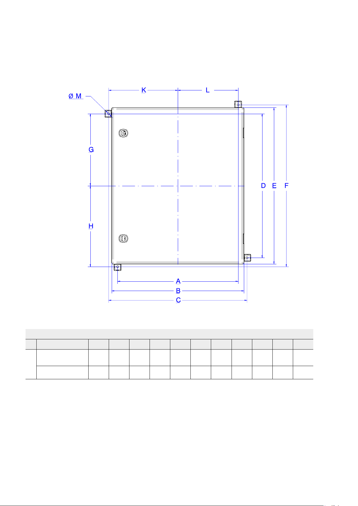
5.2 Drilling Template for Mounting
5 Assembly
Figure 6c: Dimension
Dimension (mm)
A B C D E F G H K L M
DC-CMB-U10-16
DC-CMB-U10-24
DC-CMB-U10-32 494 618 634 696 822 836 348 418 317 247 8
MODELS
Installation Manual
498 550 575 599 650 675 299.5 337.5 287.5 249 8
DC-CMB-IA-U10-xx-en
17
6 Electrical Connection
SMA Solar Technology AG
6 Electrical Connection
6.1 Connection Instructions
6.1.1 Preliminary Checks
Before connecting the Combiner Box to the photovoltaic plant, make sure that:
• The fuses are not inserted in the fuse holder.
• The disconnecting switch is open (lever set to OFF).
• The Combiner Box is in good condition and there was no damage during transport.
• The Combiner Box is firmly anchored to walls and stable supports.
• There are no remaining metallic parts, chips and derivatives from the installation activities.
After performing the checks listed in the points above, proceed to wire the cables according to what is shown in the
wiring diagram, making sure to use suitable sizes and colors. Before connecting the cables coming from the strings at
the top of the fuse holder inside the enclosure, it is recommended to join them end-to-end with suitable tips in order to
prevent possible short circuits between adjacent cables.
Note that the panel does not contain blocking diodes
If the photovoltaic array has zones that are not irradiated evenly (for example, due to partial shading), use blocking
diodes to prevent the circulation of inverse currents in the strings which may lower the system’s performance.
Make sure the yellow-green grounding conductor is connected to the arrester and to the terminal.
Make sure that the DC connections are properly secured inside the terminals in order to prevent
possible overheating that may lead to dangerous situations.
Use tools with control torque with the following data:
Fuse holders: 2 Nm
Output DC cable: Screw M12 type 70 Nm
Before closing the fuse box bases, check the entire side of the photovoltaic array for any wiring errors such as polarity
inversion of the strings or excessive voltages above the maximum permissible values. These types of wiring errors can
cause serious damage to the system or cause dangerous situations for people.
These types of wiring errors may cause fires.
18
DC-CMB-IA-U10-xx-en
Installation Manual
SMA Solar Technology AG
6 Electrical Connection
6.2 Safety during Electrical Connection
Danger to life due to electric shock
High voltages are present in the live components of the Combiner Box. Therefore, work on the
Combiner Box is only allowed if the power is disconnected and the guidelines that apply at the installation
location are strictly followed.
• Disconnect from voltage sources:
– Switch off the DC load-break switch in the Combiner Box.
– With power off, remove the DC fuses in the central inverter or main DC distribution box. Use an LV/HRC fuse
handle.
– Only open the fuse holders when the Combiner Box is switched off.
• Ensure that the device cannot be reconnected.
• Ensure that no voltage is present.
• Ground and short-circuit.
• Cover or isolate any adjacent live components. Protective covers must always be mounted.
6.3 Inserting the Cables into the Switch Cabinet
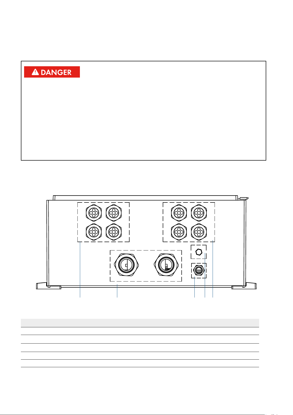
6.3.1 DC-CMB-U10-16
Figure 8: Bottom view of Combiner Box with cable glands (example)
A B C D E
Position Description
A Cable entry for connecting the strings (positive terminal)
B
C
D Protective vent
E Cable entry for connecting the strings (negative terminal)
Output DC cable gland
Grounding cable gland
Installation Manual
DC-CMB-IA-U10-xx-en
19
6 Electrical Connection
SMA Solar Technology AG
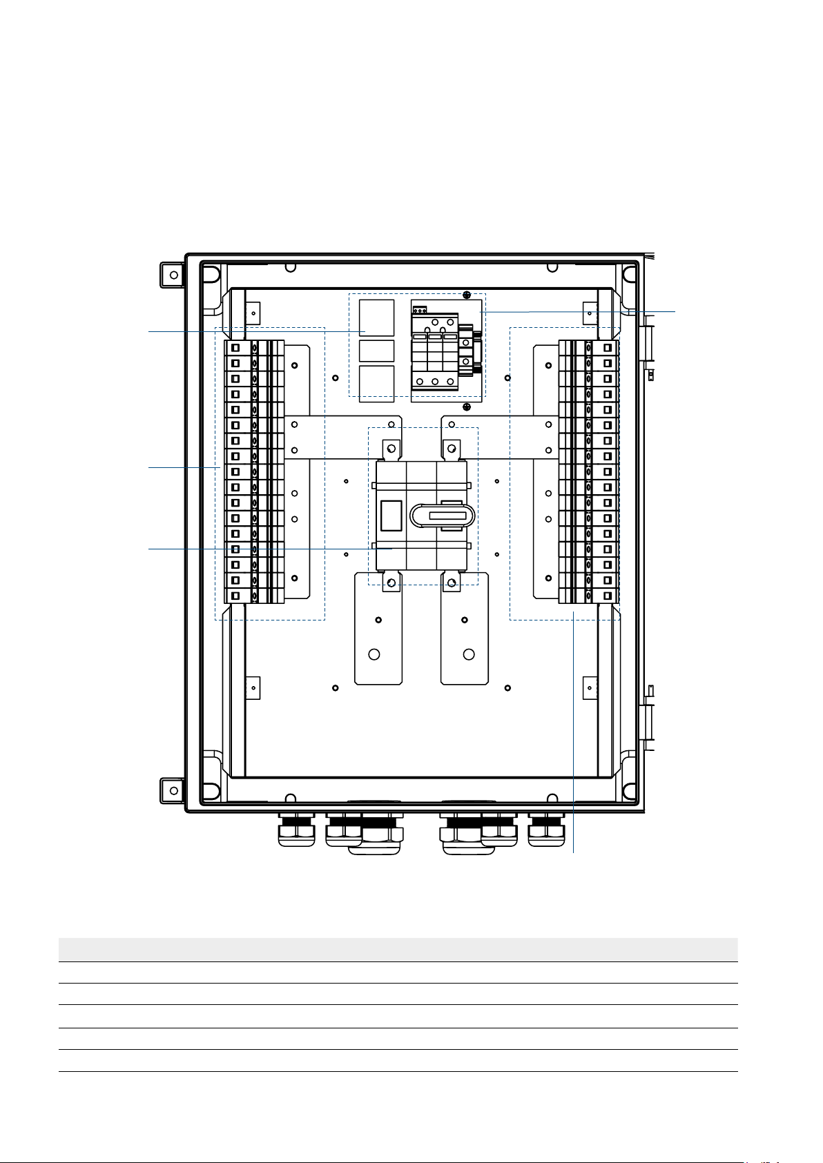
6.3.2 Overview of the Connection Area DC-CMB-U10-16
The features of the Combiner Box are dependent on the order option. The maximum configuration of the Combiner Box
is shown in the overview diagrams.
Combiner Box with cable glands for the string cables:
E
C
A
D
B
Figure 9: Connections (as exemplified in the DC-CMB-U10-16
Position Designation
A Cable entry for connecting the string (positive terminal)
B Cable entry for connecting the strings (negative terminal)
C
D Switch
E Negative input string fuse holder
20
Surge protection device
DC-CMB-IA-U10-xx-en
Installation Manual
SMA Solar Technology AG
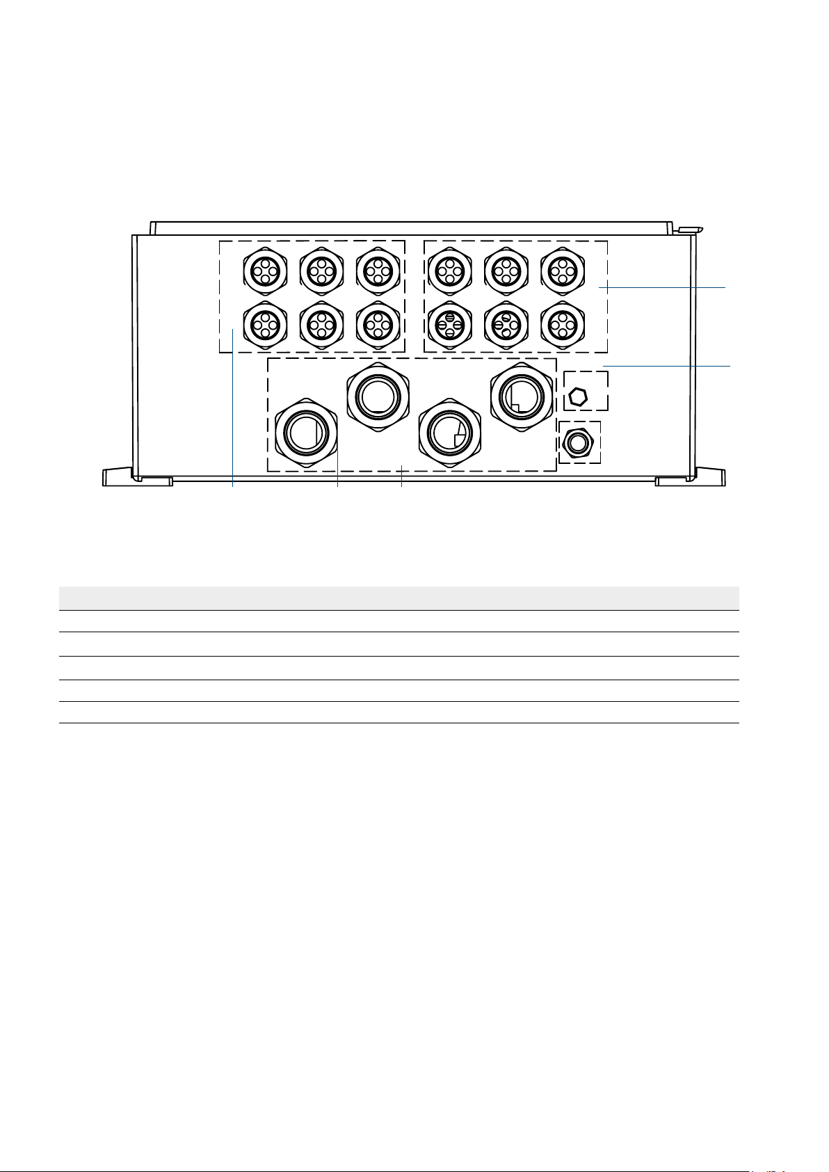
6.3.3 Inserting the Cables into the Switch Cabinet DC-CMB-U10-24
6 Electrical Connection
E
D
A B C
Figure 8: Bottom view of Combiner Box with cable glands (example)
Position Designation
A Cable entry for connecting the strings (positive terminal)
B
C
D Protective vent
E Cable entry for connecting the strings (negative terminal)
Output DC cable gland
Grounding cable gland
Installation Manual
DC-CMB-IA-U10-xx-en
21
6 Electrical Connection
SMA Solar Technology AG
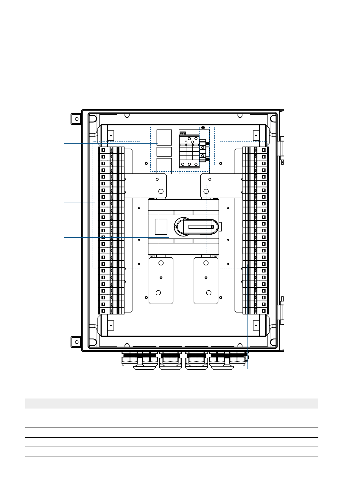
6.3.4 Overview of the Connection Area DC-CMB-U10-24
The features of the Combiner Box are dependent on the order option. The maximum configuration of the Combiner Box is
shown in the overview diagrams.
Combiner Box with cable glands for the string cables:
E
C
A
D
B
Figure 9: Connections (as exemplified in the DC-CMB-U10-24
Position Designation
A Cable entry for connecting the strings (positive terminal)
B Cable entry for connecting the strings (negative terminal)
C
D Switch
E Grounding terminal
22
Surge protection device
DC-CMB-IA-U10-xx-en
Installation Manual

SMA Solar Technology AG
6.3.5 Inserting the Cables into the Switch Cabinet DC-CMB-U10-32
6 Electrical Connection
E
D
C
A B
Figure 8: Bottom view of Combiner Box with cable glands (example)
Position Designation
A Cable entry for connecting the strings (positive terminal)
B
C
D Protective vent
E Cable entry for connecting the strings (negative terminal)
Output DC cable gland
Grounding cable gland
Installation Manual
DC-CMB-IA-U10-xx-en
23

6 Electrical Connection
SMA Solar Technology AG
6.3.6 Overview of the Connection Area DC-CMB-U10-32
The features of the Combiner Box are dependent on the order option. The maximum configuration of the Combiner Box is
shown in the overview diagrams.
Combiner Box with cable glands for the string cables:
E
C
A
D
Figure 9: Connections (as exemplified in the DC-CMB-U10-32
B
Position Designation
A Cable entry for connecting the strings + pole
B Cable entry for connecting the strings − pole
C
D Switch
E Grounding terminal
24
Surge protection device
DC-CMB-IA-U10-xx-en
Installation Manual

SMA Solar Technology AG
6 Electrical Connection
6.4 Leading the Cables through the Cable Glands with Sealing Ring Cut-Outs
Seal insert for cable glands for DC main cables:
Cable glands for the DC main cables are each supplied with two seal inserts for different cable sizes.
Cable diameter for seal insert:
24.0 mm to 38.5 mm. Use mounted seal insert.
17.0 mm to 31.0 mm. Replace seal insert for the seal insert supplied in the scope of delivery.
Procedure:
1. Release the cable gland.
2. Remove the filler plug from the cable gland.
3. When inserting the DC main cables, replace the seal insert with the insert in the scope of delivery if necessary (see
above table).
4. Lead the cable through the swivel nut of the cable gland. Ensure that the thread of the swivel nut is facing upwards.
5. Lead the cable through the seal insert.
6. Insert the seal insert into the cable gland together with the cable.
7. Cut the cable to length.
8. Tighten the cable gland with the appropriate torque:
• Cable gland for DC main cable: 7.5 Nm
6.5 Connecting the String Cables
SMA Solar Technology AG recommends using bootlace ferrules for connecting the string cables to the fuse holders.
6.5.1 Cable requirements:
o PV cable type must be available.
o Conductor cross-section of the string cable for connection of one string cable to the fuse holders:
4 mm2 to 6 mm2.
Procedure:
1. Attach the string cables to an external cable support rail.
2. Cut the string cables to length and strip 11 mm off the insulation.
3. If you are using bootlace ferrules, mount the bootlace ferrules and crimp gas-tight.
4. Connect the string cables to the screw terminals of the fuse holders (torque: 2.5 Nm). Ensure correct polarity.
6.6 Connecting the DC Main Cables
6.6.1 Cable Requirements
The Combiner Box comes supplied with busbars for connecting the DC cables with terminal lugs. If you wish to
connect the DC cables directly to the terminals, the appropriate terminals are available as accessories.
Requirements for DC main cables and terminal lugs:
o Use copper or aluminum cables only.
o Use only tin-plated copper ring terminal lugs for copper cables or bimetal ring terminal lugs for aluminum cables.
o The width of the terminal lug contact surface must exceed the diameter of the washers (32 mm).
Requirements for DC main cables for direct connection to terminals which are available as
accessories:
o Use copper or aluminum cables only.
o The conductor cross-sections of the DC main cables must be selected correctly.
o The width of terminal lug must not exceed 45 mm.
Installation Manual
DC-CMB-IA-U10-xx-en
25

6 Electrical Connection
6.7 Assembly of the Connection
6.7.1 Two Terminal Lugs
Position Designation
A Screw M12x35
B Washer
C Tin-plated copper busbar
D Fender washer
E Nut M12
F Tin-plated tube terminal lug
SMA Solar Technology AG
6.7.2 One Terminal Lug
Position Designation
A Screw M12x35
B Washer
C Tin-plated copper busbar
D Tin-plated tube terminal lug
E Fender washer
F Spring washer
G Nut M12
26
DC-CMB-IA-U10-xx-en
Installation Manual

SMA Solar Technology AG
6 Electrical Connection
6.7.3 Connection procedure:
1. Ensure that the DC subdistribution is switched off and secured against reconnection (see Section 8 “Disconnecting and
Reconnecting”).
2. Ensure that the inverter is disconnected on the DC side and secured against reconnection (see inverter manual).
3. Lead the DC main cables into the DC subdistribution through the designated enclosure opening (see Section 6) with
the appropriate seal insert (see Section 6).
4. Fit the DC main cables with tube terminal lugs. Make sure that no pieces of cable are dropped into the DC subdistri-
bution.
5. In the DC subdistribution, remove the fastening material for the DC main cables from the busbars.
6. Clean the contact surfaces using a clean cloth and ethanol cleaning agent. Do not touch the contact surfaces after
cleaning.
Additionally required material (not included in the scope of delivery):
o Ring terminal lugs (size: for M12 screw)
o Clean cloth
o Ethanol cleaning agent
Procedure:
1. Strip off the DC cable insulation.
2. Fit the DC main cables with ring terminal lugs.
3. Clean the contact surfaces using a clean cloth and ethanol cleaning agent. Do not touch the contact surfaces after
cleaning.
4. Connect the DC main cables in accordance with the circuit diagram (torque: 60 Nm). Ensure that you only use the
supplied fastening material and connect a maximum of two adjacent DC main cables to each busbar.
5. Secure the DC main cables to the cable support rail.
6.8 Connecting the Grounding Cable
In order to guarantee the function of the surge arrester, it must be connected to the external grounding.
Cable requirement:
o Conductor cross-section:16 mm2 to 35 mm2.
Procedure:
1. Strip 16 mm off the grounding cable insulation.
2. Connect the grounding cable to the screw terminal of the surge arrester (torque: 2.5 Nm).
3. Ensure that the grounding cable is securely clamped.
4. Ground the grounding cable in the vicinity of the Combiner Box, e.g. by means of a grounding electrode.
Installation Manual
DC-CMB-IA-U10-xx-en
27
7 Commissioning
SMA Solar Technology AG
7 Commissioning
7.1 Safety during Commissioning
Danger to life from electric shock due to live voltage
• High voltages are present in the live components of the Combiner Box. Touching live components results in death
or serious injury due to electric shock.
• Wear personal protective equipment when working on the Combiner Box.
• Do not touch live components.
• Before performing any work, always disconnect the Combiner Box from voltage sources unless supply
• voltage is absolutely necessary.
– Switch off the DC load-break switch in the Combiner Box.
– With power off, remove the DC fuses in the central inverter or main DC distribution box. Use the LV/HRC fuse
handle to do this.
– Only open the fuse holders when the Combiner Box is switched off.
• Ensure that the device cannot be reconnected.
• Ensure that no voltage is present.
• Ground and short-circuit.
• Cover or isolate any adjacent live components. Protective covers must always be mounted.
7.2 Commissioning the Combiner Box
7.2.1 Requirements for Commissioning
Commissioning must be performed by Service employees only
Commissioning of the Combiner Box must be performed by Service employees of SMA Solar Technology AG
or their authorized representatives only.
The commissioning report must be completed during commissioning.
Requirements:
o The DC load-break switch is switched off.
o The DC main cables are connected to the inverter or main DC distribution box and disconnected from voltage
sources.
o There is no reverse voltage from the inverter.
o All connections have been made in accordance with this manual (see Section 6 “Electrical Connection”, page 17).
o The correct polarity of all connections has been ensured and documented.
o The floor around the Combiner Boxs is firm and freely accessible.
7.3 Voltage Check – Measuring Procedure
Use a voltmeter with a voltage range up to 1,500 VDC. This check is made by
measuring the open-circuit voltage of the panels obtained at minimum irradiation.
Requirements:
· Make sure that the inverter is switched off and disconnected on the DC side.
· Make sure that the disconnecting switch of the combiner is set to OFF.
· Make sure that the fuse box bases are open.
28
DC-CMB-IA-U10-xx-en
Installation Manual
SMA Solar Technology AG
7 Commissioning
Measure the open-circuit voltage of each string and check the following points:
· The maximum deviation between the voltages is less than 10%.
· No values higher than the maximum permissible are measured.
· No negative values are measured.
The fuses can be inserted in the fuse boxes only if the previous tests have generated positive results.
Proceed with the start-up operations of the system.
Immediately correct the wiring if one of the aforesaid conditions is not valid because continuation
of this situation may cause serious damage to the system and people.
7 Commissioning
The fuse holders are not suitable for isolating the on-load string current. Therefore, these bases should only be opened if
there is no passage of current (main disconnecting switch OFF) in order to prevent the creation of electrical arcs that are
dangerous to the health and safety of people and the intactness of components.
Installation Manual
DC-CMB-IA-U10-xx-en
29
8 Maintenance
SMA Solar Technology AG
8 Maintenance
8.1 Periodic Maintenance
It is recommended to periodically inspect the panel and check the following points:
• There are no evident signs of rust or corrosion which may impair functioning and safety.
(Yearly - Visual inspection)
• There are no water infiltrations and excessive dust infiltration.
(Yearly - Visual inspection)
• The mass grounding and drains are efficient.
(Yearly - Visual inspection)
• There is insulation between the electrical circuits and masses.
(5 Year - Insulation test)
• All the DC and AC connections are correctly tightened.
(Yearly - Dynamometric torque tool)
• There are no burn marks on the terminals.
(Yearly - Visual inspection)
• The door panel of the enclosure is firmly closed at the end of all the checks and after any maintenance.
(Yearly - Visual inspection)
8.2 Extraordinary Maintenance
If damaged components need to be replaced (for example, fuses, SPD, etc.) only use materials identical to those originally
supplied. A list of these materials is available in the wiring Diagram. If in doubt, contact the manufacturer.
If the electrical connections are damaged due to mechanical or electrical causes or due to rodents, immediately
disconnect the system or at least the damaged part. After verifying that no failures were caused to the equipment, proceed
with the replacement of the wires using similar materials.
All the maintenance operations must be performed by taking into account all safety instructions, checking beforehand
that the components are not powered.
30
DC-CMB-IA-U10-xx-en
Installation Manual
 Loading...