

Page 1
SUNNY BOY
WINDY BOY
Version: 1.0 Mat.-Nr.: DB-SB-ERD
Zusätzliche Erdung des Gehäuses
Mise à la terre supplémentaire du boîtier
Additional Grounding of the Enclosure
2
4
6
1/7 SB_Erdung-IXX104810
Page 2
SMA Solar Technology AG Hinweise zu dieser Anleitung
1 Hinweise zu dieser Anleitung
Diese Anleitung beschreibt den Anschluss eines zweiten Schutzleiters am Gehäuse folgender
SMAWechselrichter:
• Sunny Boy 1200 (SB 1200) • Sunny Boy 1700 (SB1700)
• Sunny Boy 2100TL (SB 2100TL) • Sunny Boy 2500 (SB 2500)
• Sunny Boy 3000 (SB 3000) • Sunny Boy 3300TL HC (SB 3300TL HC)
• Sunny Boy 3300 (SB 3300) • Sunny Boy 3800 (SB 3800)
• Windy Boy 1200 (WB 1200) • Windy Boy 1700 (WB 1700)
• Windy Boy 2500 (WB 2500) • Windy Boy 3000 (WB 3000)
• Windy Boy 3300 (WB 3300) • Windy Boy 3800 (WB 3800)
Durch die zusätzliche Erdung des Gehäuses können Sie den in einigen Ländern (z. B. Frankreich,
Schweiz) geforderten, zweiten Schutzleiter-Anschluss realisieren.
2 Zusätzliche Erdung anschließen
GEFAHR!
Lebensgefahr durch hohe Spannungen im Wechselrichter!
• Alle Arbeiten am Wechselrichter dürfen nur im freigeschaltetem Zustand und durch
eine ausgebildete Elektrofachkraft erfolgen.
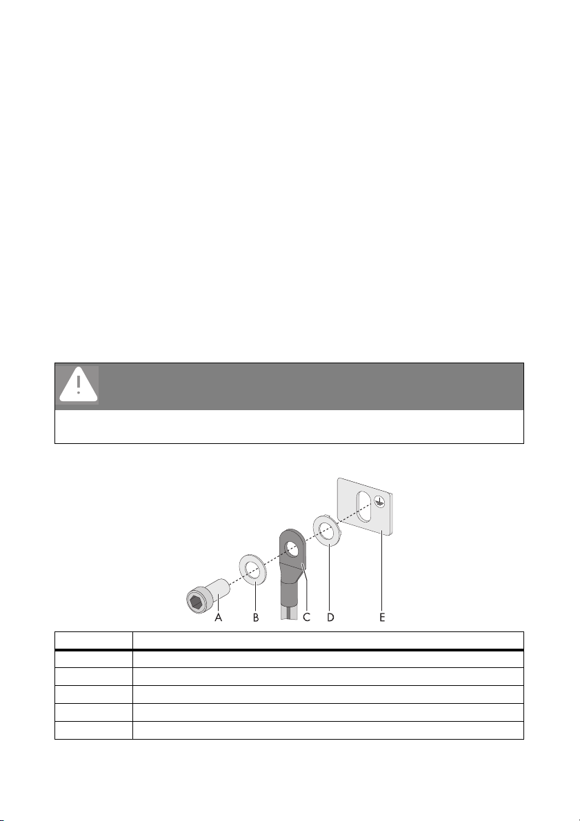
Übersicht
Objekt Beschreibung
A M6x12 Zylinderschraube (im Lieferumfang des Wechselrichters enthalten)
B Unterlegscheibe
C Kabelschuh (M6) mit Schutzleiter
D Sperrkantscheibe (im Lieferumfang des Wechselrichters enthalten)
E Metalllasche an der Gehäuseunterseite des Wechselrichters
2/7 SB_Erdung-IXX104810
Page 3

SMA Solar Technology AG Zusätzliche Erdung anschließen
Vorgehensweise bei SB 1200/1700, SB 2100TL, SB 2500/3000, SB 3300TL HC,
WB 1200/1700, WB 2500/3000
1. Den Wechselrichter AC- und DC-seitig freischalten, wie in der Installationsanleitung des
Wechselrichters beschrieben.
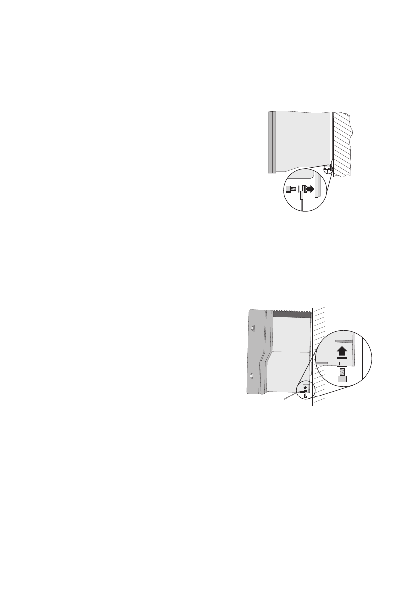
2. Unterlegscheibe, Kabelschuh mit Schutzleiter und
Sperrkantscheibe auf der Zylinderschraube
anordnen. Die Verzahnung der Sperrkantscheibe
muss zur Metalllasche zeigen.
3. Zylinderschraube durch die Metalllasche an der
Gehäuseunterseite stecken und im unteren Loch der
Wandhalterung festdrehen. Dabei
Zylinderschraube mit einem Drehmoment von
6Nm anziehen.
4. Kontakt zwischen Schutzleiter und Gehäuse
gemäß den im Installationsland geltenden
Vorschriften prüfen.
Vorgehensweise bei SB 3300/3800, WB 3300/3800
1. Den Wechselrichter AC- und DC-seitig freischalten, wie in der Installationsanleitung des
Wechselrichters beschrieben.
2. Unterlegscheibe, Kabelschuh mit Schutzleiter und
Sperrkantscheibe auf der Zylinderschraube
anordnen. Die Verzahnung der Sperrkantscheibe
muss zur Metalllasche zeigen.
3. Zylinderschraube in Metalllasche stecken und mit
einem Drehmoment von 6Nm anziehen.
4. Kontakt zwischen Schutzleiter und Gehäuse
gemäß den im Installationsland geltenden
Vorschriften prüfen.
3/7 SB_Erdung-IXX104810
Page 4

SMA Solar Technology AG Remarques concernant ces instructions d'installation
1 Remarques concernant ces instructions d'installation
Ces instructions décrivent le raccordement d'un second conducteur de protection au boîtier des
onduleursSMA suivants:
• Sunny Boy 1200 (SB 1200) • Sunny Boy 1700 (SB1700)
• Sunny Boy 2100TL (SB 2100TL) • Sunny Boy 2500 (SB 2500)
• Sunny Boy 3000 (SB 3000) • Sunny Boy 3300TL HC (SB 3300TL HC)
• Sunny Boy 3300 (SB 3300) • Sunny Boy 3800 (SB 3800)
• Windy Boy 1200 (WB 1200) • Windy Boy 1700 (WB 1700)
• Windy Boy 2500 (WB 2500) • Windy Boy 3000 (WB 3000)
• Windy Boy 3300 (WB 3300) • Windy Boy 3800 (WB 3800)
Cette mise à la terre supplémentaire du boîtier permet de satisfaire à l'exigence d'un second
conducteur de protection, en vigueur dans certains pays (par exemple la France et la Suisse).
2 Raccordement d'une mise à la terre supplémentaire
DANGER !
Haute tension dans l'onduleur. Danger de mort !
• Tous les travaux sur l'onduleur doivent être effectués en mode déconnecté et par un
électricien qualifié.
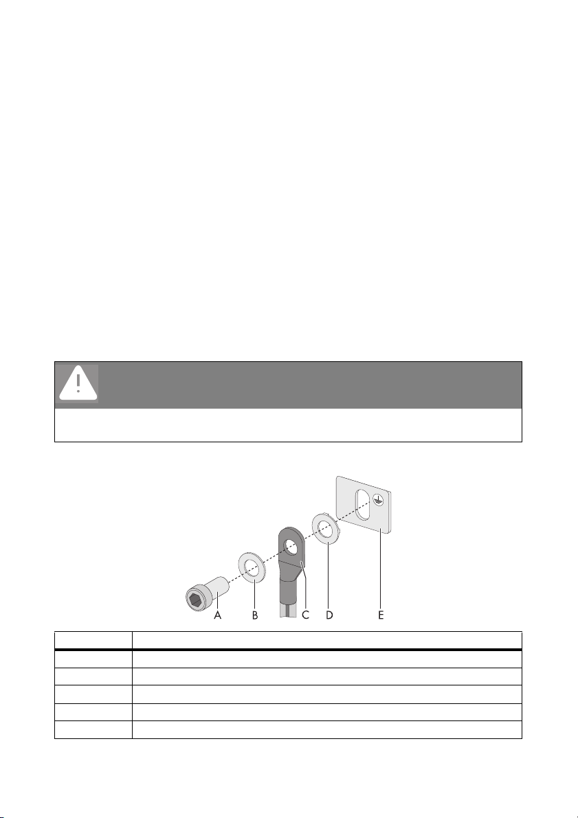
Aperçu
Objet Description
A Vis à tête cylindrique M6x12 (fournie avec l'onduleur)
B Rondelle
C Cosse de câble (M6) avec conducteur de protection
D Rondelle autobloquante (fournie avec l'onduleur)
E Languette métallique située sous le boîtier de l'onduleur
4/7 SB_Erdung-IXX104810
Page 5
SMA Solar Technology AG Raccordement d'une mise à la terre supplémentaire
Procédure lors du raccordement des SB 1200/1700, SB 2100TL, SB 2500/3000,
SB 3300TL HC, WB 1200/1700, WB 2500/3000
1. Déconnectez l'onduleur côtés AC et DC comme décrit dans les instructions d'installation de
l'onduleur.
2. Insérez la rondelle, la cosse avec le conducteur de
protection et la rondelle autobloquante sur la vis à
tête cylindrique dans l'ordre indiqué. Les dents de la
rondelle autobloquante doivent pointer en
direction de la languette métallique.
3. Insérez la vis à tête cylindrique dans la languette
métallique située sous le boîtier et vissez-la dans le
trou inférieur du support mural. Serrez la vis à tête
cylindrique à un couple de 6 Nm.
4. Vérifiez que le contact entre le conducteur de
protection et le boîtier est conforme à la
réglementation en vigueur dans le pays concerné.
Procédure lors du raccordement des SB 3300/3800, WB 3300/3800
1. Déconnectez l'onduleur côtés AC et DC comme décrit dans les instructions d'installation de
l'onduleur.
2. Insérez la rondelle, la cosse avec le conducteur de
protection et la rondelle autobloquante sur la vis à
tête cylindrique dans l'ordre indiqué. Les dents de la
rondelle autobloquante doivent pointer en
direction de la languette métallique.
3. Insérez la vis à tête cylindrique dans la languette
métallique à un couple de 6 Nm.
4. Vérifiez que le contact entre le conducteur de
protection et le boîtier est conforme à la
réglementation en vigueur dans le pays concerné.
5/7 SB_Erdung-IXX104810
Page 6
SMA Solar Technology AG Notes on this manual
1 Notes on this manual
This guide describes the connection of a second protective grounder to the housings of the following
inverters.
• Sunny Boy 1200 (SB 1200) • Sunny Boy 1700 (SB1700)
• Sunny Boy 2100TL (SB 2100TL) • Sunny Boy 2500 (SB 2500)
• Sunny Boy 3000 (SB 3000) • Sunny Boy 3300TL HC (SB 3300TL HC)
• Sunny Boy 3300 (SB 3300) • Sunny Boy 3800 (SB 3800)
• Windy Boy 1200 (WB 1200) • Windy Boy 1700 (WB 1700)
• Windy Boy 2500 (WB 2500) • Windy Boy 3000 (WB 3000)
• Windy Boy 3300 (WB 3300) • Windy Boy 3800 (WB 3800)
With this additional grounding of the enclosure you can install the second grounding conductor
connection in those countries where this is a requirement (such as France, Switzerland).
2 Connecting Additional Grounding
DANGER!
Danger to life due to high voltages in the inverter.
• All work on the inverter must be carried out by a qualified personnel and only when
the device is disconnected from the power supply.
Overview
Object Description
A M6 x 12 cylinder head screw (included in scope of delivery of the inverter)
B Washer
C Terminal lug (M6) with grounding conductor
D Tooth lock washer (included in inverter delivery)
E Metal shackle on the underside of the inverter enclosure
6/7 SB_Erdung-IXX104810
Page 7
SMA Solar Technology AG Connecting Additional Grounding
Connection Procedure for SB 1200/1700, SB 2100TL, SB 2500/3000,
SB 3300TL HC, WB 1200/1700, WB 2500/3000
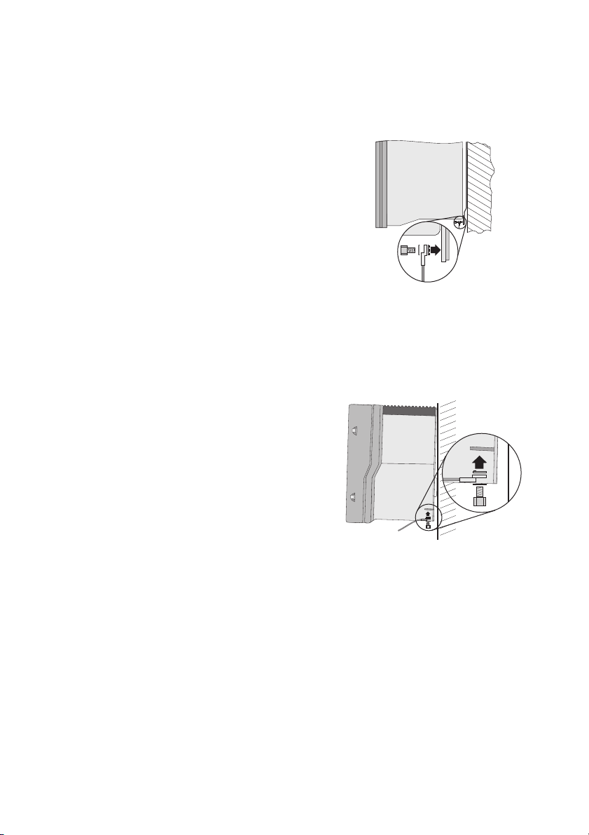
1. Disconnect the inverter on the AC and DC sides as described in the inverter's installation guide.
2. Fit the washer, terminal lug with grounding
conductor and tooth lock washer onto the cylinder
head screw. The toothing of the tooth lock washer
must face toward the metal shackle.
3. Insert the cylinder head screw into the metal
shackle an the underside of the enclosure and
screw tightly into the lower hole of the wall bracket.
Tighten the cylinder head screw using a torque of
6Nm.
4. Check that the contact between the grounding
conductor and the enclosure is in accordance with
the regulations valid for the country of installation.
Connection Procedure for SB 3300/3800, WB 3300/3800
1. Disconnect the inverter on the AC and DC sides as described in the inverter's installation guide.
2. Fit the washer, terminal lug with grounding
conductor and tooth lock washer onto the cylinder
head screw. The toothing of the tooth lock washer
must face toward the metal shackle.
3. Insert the cylinder head screw into the metal
shackle and tighten it using a torque of 6 Nm.
4. Check that the contact between the grounding
conductor and the enclosure is in accordance with
the regulations valid for the country of installation.
7/7 SB_Erdung-IXX104810
Page 8

 Loading...