

Page 1
Installation Manual
Communit
Communit-IA-A1-en-22 | 98-127900.02 | Version 2.2 ENGLISH
Page 2

Legal Provisions SMA Solar Technology AG
Legal Provisions
The information contained in this document is the property of SMA Solar Technology AG. Publishing its content, either
partially or in full, requires the written permission of SMA Solar Technology AG. Any internal company copying of the
document for the purposes of evaluating the product or its correct implementation is allowed and does not require
permission.
SMA Warranty
You can download the current warranty conditions from the Internet at www.SMA-Solar.com.
Trademarks
All trademarks are recognized, even if not explicitly identified as such. A lack of identification does not mean that a
product or symbol is not trademarked.
The BLUETOOTH
marks by SMA Solar Technology AG is under license.
Modbus
®
is a registered trademark of Schneider Electric and is licensed by the Modbus Organization, Inc.
QR Code is a registered trademark of DENSO WAVE INCORPORATED.
®
Phillips
Torx
and Pozidriv® are registered trademarks of Phillips Screw Company.
®
is a registered trademark of Acument Global Technologies, Inc.
®
word mark and logos are registered trademarks owned by Bluetooth SIG, Inc. and any use of these
SMA Solar Technology AG
Sonnenallee 1
34266 Niestetal
Germany
Tel. +49 561 9522-0
Fax +49 561 9522-100
www.SMA.de
E-mail: info@SMA.de
© 2004 to 2015 SMA Solar Technology AG. All rights reserved.
2 Communit-IA-A1-en-22 Installation Manual
Page 3

SMA Solar Technology AG Table of Contents
Table of Contents
1 Information on this Document. . . . . . . . . . . . . . . . . . . . . . . . . . . . . . . . . . . . . . . . . . . . . . . . . . . . . 5
1.1 Validity . . . . . . . . . . . . . . . . . . . . . . . . . . . . . . . . . . . . . . . . . . . . . . . . . . . . . . . . . . . . . . . . . . . . . . . . . . . . . . 5
1.2 Target Group . . . . . . . . . . . . . . . . . . . . . . . . . . . . . . . . . . . . . . . . . . . . . . . . . . . . . . . . . . . . . . . . . . . . . . . . . 5
1.3 Additional Information . . . . . . . . . . . . . . . . . . . . . . . . . . . . . . . . . . . . . . . . . . . . . . . . . . . . . . . . . . . . . . . . . . 5
1.4 Symbols . . . . . . . . . . . . . . . . . . . . . . . . . . . . . . . . . . . . . . . . . . . . . . . . . . . . . . . . . . . . . . . . . . . . . . . . . . . . . 5
1.5 Typographies . . . . . . . . . . . . . . . . . . . . . . . . . . . . . . . . . . . . . . . . . . . . . . . . . . . . . . . . . . . . . . . . . . . . . . . . . 6
1.6 Nomenclature. . . . . . . . . . . . . . . . . . . . . . . . . . . . . . . . . . . . . . . . . . . . . . . . . . . . . . . . . . . . . . . . . . . . . . . . . 6
1.7 Abbreviations . . . . . . . . . . . . . . . . . . . . . . . . . . . . . . . . . . . . . . . . . . . . . . . . . . . . . . . . . . . . . . . . . . . . . . . . . 6
2 Safety . . . . . . . . . . . . . . . . . . . . . . . . . . . . . . . . . . . . . . . . . . . . . . . . . . . . . . . . . . . . . . . . . . . . . . . . 7
2.1 Intended Use . . . . . . . . . . . . . . . . . . . . . . . . . . . . . . . . . . . . . . . . . . . . . . . . . . . . . . . . . . . . . . . . . . . . . . . . . 7
2.2 Safety Information . . . . . . . . . . . . . . . . . . . . . . . . . . . . . . . . . . . . . . . . . . . . . . . . . . . . . . . . . . . . . . . . . . . . . 8
3 Product Description . . . . . . . . . . . . . . . . . . . . . . . . . . . . . . . . . . . . . . . . . . . . . . . . . . . . . . . . . . . . 10
3.1 Communit . . . . . . . . . . . . . . . . . . . . . . . . . . . . . . . . . . . . . . . . . . . . . . . . . . . . . . . . . . . . . . . . . . . . . . . . . . . 10
3.2 Type Label . . . . . . . . . . . . . . . . . . . . . . . . . . . . . . . . . . . . . . . . . . . . . . . . . . . . . . . . . . . . . . . . . . . . . . . . . . 10
4 Scope of Delivery. . . . . . . . . . . . . . . . . . . . . . . . . . . . . . . . . . . . . . . . . . . . . . . . . . . . . . . . . . . . . . 12
5 Mounting. . . . . . . . . . . . . . . . . . . . . . . . . . . . . . . . . . . . . . . . . . . . . . . . . . . . . . . . . . . . . . . . . . . . . 14
5.1 Selecting the Mounting Location . . . . . . . . . . . . . . . . . . . . . . . . . . . . . . . . . . . . . . . . . . . . . . . . . . . . . . . . . 14
5.2 Mounting the Communit on the Wall . . . . . . . . . . . . . . . . . . . . . . . . . . . . . . . . . . . . . . . . . . . . . . . . . . . . . . 15
5.3 Mounting the Communit with Base. . . . . . . . . . . . . . . . . . . . . . . . . . . . . . . . . . . . . . . . . . . . . . . . . . . . . . . . 17
5.4 Determining the Optimum Mounting Location for the Antenna . . . . . . . . . . . . . . . . . . . . . . . . . . . . . . . . . . 19
5.5 Mounting the Antenna . . . . . . . . . . . . . . . . . . . . . . . . . . . . . . . . . . . . . . . . . . . . . . . . . . . . . . . . . . . . . . . . . 20
5.6 Installing Your Own Optional Device. . . . . . . . . . . . . . . . . . . . . . . . . . . . . . . . . . . . . . . . . . . . . . . . . . . . . . 20
6 Electrical Connection . . . . . . . . . . . . . . . . . . . . . . . . . . . . . . . . . . . . . . . . . . . . . . . . . . . . . . . . . . . 22
6.1 Overview of the Connection Area . . . . . . . . . . . . . . . . . . . . . . . . . . . . . . . . . . . . . . . . . . . . . . . . . . . . . . . . 22
6.2 Inserting the Cables into the Communication Distribution Unit . . . . . . . . . . . . . . . . . . . . . . . . . . . . . . . . . . . 23
6.3 Connecting the Cables to the Connecting Terminal Plates . . . . . . . . . . . . . . . . . . . . . . . . . . . . . . . . . . . . . . 24
6.3.1 Connecting Conductors to the Spring-Cage Terminal . . . . . . . . . . . . . . . . . . . . . . . . . . . . . . . . . . . . . . . . . . . .24
6.3.2 Connecting the Cable Shield Contact . . . . . . . . . . . . . . . . . . . . . . . . . . . . . . . . . . . . . . . . . . . . . . . . . . . . . . . .25
6.3.3 Connecting the Communit Supply Voltage . . . . . . . . . . . . . . . . . . . . . . . . . . . . . . . . . . . . . . . . . . . . . . . . . . . .25
6.3.4 Connecting the Cables for the SMA Cluster Controller . . . . . . . . . . . . . . . . . . . . . . . . . . . . . . . . . . . . . . . . . . .26
6.3.5 Connecting the Cables for the I/O Modules. . . . . . . . . . . . . . . . . . . . . . . . . . . . . . . . . . . . . . . . . . . . . . . . . . .26
6.3.6 Connecting the RS485 Cable of the Sunny SensorBox. . . . . . . . . . . . . . . . . . . . . . . . . . . . . . . . . . . . . . . . . . .27
6.3.7 Connecting the Voltage Supply of Your Own Optional Devices. . . . . . . . . . . . . . . . . . . . . . . . . . . . . . . . . . . .28
6.4 Connecting the Cables to the Network Switch and Router . . . . . . . . . . . . . . . . . . . . . . . . . . . . . . . . . . . . . 29
6.4.1 Connecting the Network Cables to the Network Switch . . . . . . . . . . . . . . . . . . . . . . . . . . . . . . . . . . . . . . . . . .29
6.4.2 Connecting the Cable to the Router. . . . . . . . . . . . . . . . . . . . . . . . . . . . . . . . . . . . . . . . . . . . . . . . . . . . . . . . . .30
6.5 Splicing and Connecting the Optical Fiber. . . . . . . . . . . . . . . . . . . . . . . . . . . . . . . . . . . . . . . . . . . . . . . . . . 30
6.6 Connecting the Network Cable via the Keystone Jack. . . . . . . . . . . . . . . . . . . . . . . . . . . . . . . . . . . . . . . . . 31
7 Commissioning the Communit. . . . . . . . . . . . . . . . . . . . . . . . . . . . . . . . . . . . . . . . . . . . . . . . . . . . 33
7.1 Information on Commissioning . . . . . . . . . . . . . . . . . . . . . . . . . . . . . . . . . . . . . . . . . . . . . . . . . . . . . . . . . . . 33
7.2 Configuring the Router . . . . . . . . . . . . . . . . . . . . . . . . . . . . . . . . . . . . . . . . . . . . . . . . . . . . . . . . . . . . . . . . . 33
7.3 Configuring the Network Switch. . . . . . . . . . . . . . . . . . . . . . . . . . . . . . . . . . . . . . . . . . . . . . . . . . . . . . . . . . 35
Installation Manual Communit-IA-A1-en-22 3
Page 4

Table of Contents SMA Solar Technology AG
7.4 Commissioning the Sunny WebBox. . . . . . . . . . . . . . . . . . . . . . . . . . . . . . . . . . . . . . . . . . . . . . . . . . . . . . . 35
8 Communit Maintenance Work. . . . . . . . . . . . . . . . . . . . . . . . . . . . . . . . . . . . . . . . . . . . . . . . . . . .36
8.1 Maintenance Interval . . . . . . . . . . . . . . . . . . . . . . . . . . . . . . . . . . . . . . . . . . . . . . . . . . . . . . . . . . . . . . . . . . 36
8.2 Checking the Mounting Location and Installation of the Communit. . . . . . . . . . . . . . . . . . . . . . . . . . . . . . . 36
8.3 Checking the Enclosure and Enclosure Interior . . . . . . . . . . . . . . . . . . . . . . . . . . . . . . . . . . . . . . . . . . . . . . 36
8.4 Checking the Supply Voltage. . . . . . . . . . . . . . . . . . . . . . . . . . . . . . . . . . . . . . . . . . . . . . . . . . . . . . . . . . . . 36
9 Decommissioning . . . . . . . . . . . . . . . . . . . . . . . . . . . . . . . . . . . . . . . . . . . . . . . . . . . . . . . . . . . . . .37
9.1 Disassembling the Communit . . . . . . . . . . . . . . . . . . . . . . . . . . . . . . . . . . . . . . . . . . . . . . . . . . . . . . . . . . . . 37
9.2 Disposing of the Communit . . . . . . . . . . . . . . . . . . . . . . . . . . . . . . . . . . . . . . . . . . . . . . . . . . . . . . . . . . . . . 37
10 Troubleshooting . . . . . . . . . . . . . . . . . . . . . . . . . . . . . . . . . . . . . . . . . . . . . . . . . . . . . . . . . . . . . . .38
11 Technical Data. . . . . . . . . . . . . . . . . . . . . . . . . . . . . . . . . . . . . . . . . . . . . . . . . . . . . . . . . . . . . . . . .39
12 Contact. . . . . . . . . . . . . . . . . . . . . . . . . . . . . . . . . . . . . . . . . . . . . . . . . . . . . . . . . . . . . . . . . . . . . . .42
4 Communit-IA-A1-en-22 Installation Manual
Page 5
SMA Solar Technology AG 1 Information on this Document
1 Information on this Document
1.1 Validity
This document is valid for the device type "Communit-10" from production version A1.
1.2 Target Group
The tasks described in this document must be performed by qualified persons only. Qualified persons must have the
following skills:
• Knowledge of how a communication distribution unit works and is operated
• Training in how to deal with the dangers and risks associated with installing and using electrical devices and
installations
• Training in the installation and commissioning of electrical devices and installations
• Training in the installation and configuration of IT systems
• Knowledge of and skills in the splicing of optical fibers
• Knowledge of all applicable standards and directives
• Knowledge of and adherence to this manual, the manuals of the communication devices including the specified
safety information
1.3 Additional Information
Links to additional information can be found at www.SMA-Solar.com:
Document title Document type
Communit Technical Information
Plant Communication in Large-Scale PV Power Plants Technical Information
RS485 Cabling Plan Installation Manual
Further information on the operation of optional communication devices in the Communit such as the patch panel, the
router or the network switches can be found on the website of the respective manufacturer and at www.SMA-Solar.com.
1.4 Symbols
Symbol Explanation
'$1*(5
:$5 1,1*
&$87,21
/05*$&
Indicates a hazardous situation which, if not avoided, will result in death or serious injury
Indicates a hazardous situation which, if not avoided, can result in death or serious injury
Indicates a hazardous situation which, if not avoided, can result in minor or moderate injury
Indicates a situation which, if not avoided, can result in property damage
Information that is important for a specific topic or goal, but is not safety-relevant
☐ Indicates a requirement for meeting a specific goal
☑ Desired result
✖ A problem that might occur
Installation Manual Communit-IA-A1-en-22 5
Page 6

1 Information on this Document SMA Solar Technology AG
1.5 Typographies
Typography Use Example
Bold • Elements to be selected
• Elements to be entered
> • Several elements that are to be selected • Select Connectivity Settings > Internet
[Button/Key] • Button or key to be selected or pressed • Select [SAVE].
•Select Home in the menu.
Settings in the menu.
1.6 Nomenclature
In this document, the Communit is also designated as the communication distribution unit.
1.7 Abbreviations
Abbreviation Designation Explanation
APN Access Point Name Name of connection point in a GPRS backbone, allowing access
to an external packet data network
GSM Global System for Mobile
Communication
IP Internet Protocol -
IT Information Technology ‒
MMF Multi-Mode Fibre Optical fibre transmitting signals at several wavelengths
-
OF Optical Fibre ‒
PIN Personal Identification
Number
PV Photovoltaik ‒
SC Subscriber Connector Plug for connection via optical fibre
SIM Subscriber Identity Module Card used to identify a subscriber on mobile communication
SMF Single-Mode Fibre Optical fibre transmitting signals at one wavelength
UMTS Universal Mobile
Telecommunications System
–
devices
System succeeding GSM
6 Communit-IA-A1-en-22 Installation Manual
Page 7
SMA Solar Technology AG 2 Safety
2 Safety
2.1 Intended Use
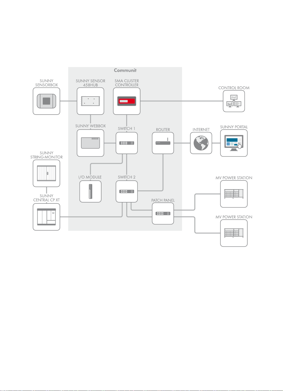
The Communit is a central communication distribution unit of a large-scale PV power plant integrating all the
communication devices.
Figure1: Communit in a large-scale PV power plant (example)
The Communit is suitable for indoor and outdoor use.
The Communit can be used in large-scale PV power plants with Sunny Central, Sunny Mini Central or Sunny Tripower.
If you have selected the option "Customer Installation Location" in the option code of the Communit, the Communit is
supplied with one or two installation locations for your own communication devices. During installation, observe the
requirements for each device to be installed:
• The device must be approved for operation at the mounting location, e.g. the device must have a valid declaration
of conformity in Europe.
• The device must have the following technical data:
– Permissible ambient temperatures: ‒20°C to +60°C
– Emitted interference: Class A (as per EN55022: 2006+A1: 2007)
– Interference immunity: Class A (as per EN55024: 1998+A1: 2001 +A2:2003)
• The device can be mounted on a top-hat rail.
• The device has suitable dimensions for the available space: 226 mm x 130 mm x 71 mm (width x height x depth).
Installation Manual Communit-IA-A1-en-22 7
Page 8
2 Safety SMA Solar Technology AG
• The device must be suitable for connection to voltage supply:
– Device for installation location 1: AC voltage supply, maximum power consumption 20 W or DC voltage supply;
information on maximum power consumption, see the Technical Information "Communit"
– Device for installation location 2: only DC voltage supply; information on maximum power consumption, see the
Technical Information "Communit"
For optimum operation of the Communit, observe the requirements for the mounting location (see Section5.1 "Selecting
the Mounting Location", page14).
Use this product only in accordance with the information provided in the enclosed documentation and with the locally
applicable standards and directives. Any other application may cause personal injury or property damage.
Alterations to the product, e.g. modifications or conversions, are only permitted with the express written permission of
SMA Solar Technology AG. Making unauthorized changes will void the warranty and warranty claims and will normally
result in invalidation of the operating permit. SMA Solar Technology AG shall not be held liable for any damage caused
by such changes.
Any use of the product other than described in the Intended Use section does not qualify as appropriate.
The enclosed documentation is an integral part of this product. Keep the documentation in a convenient place for future
reference and observe all instructions contained therein.
The type label must remain permanently attached to the product.
2.2 Safety Information
This section contains safety information that must be observed at all time s when working on or with the product. To prevent
personal injury and property damage and to ensure long-term operation of the product, read this section carefully and
observe all safety information at all times.
'$1*(5
Danger to life due to electric shock when voltage is present
Danger of electric shock if work is executed incorrectly or under fault conditions.
• Disconnect the supply voltage before performing any work on the Communit.
• Observe the five safety rules when disconnecting the supply voltage:
– Disconnect the device from voltage sources.
– Ensure that the device cannot be reconnected.
– Ensure that no voltage is present.
– Ground and short-circuit the device.
– Cover and isolate any adjacent live components.
&$87,21
Damage to eyes and skin due to visible and invisible laser radiation
The Communit contains class 1 LED or laser components in accordance with IEC 60825-1 (2003). Invisible laser
radiation, wave length: 1,300 nm.
The laser beam appears at the end of the optical fiber.
• Do not look into the laser beam.
• Do not look at the laser beam using optical instruments.
• Do not point the laser beam at people.
8 Communit-IA-A1-en-22 Installation Manual
Page 9
SMA Solar Technology AG 2 Safety
/05*$&
Property damage due to tampering
The product and the PV system can be damaged when tampered with.
• Always close and lock the product.
• Remove the key from the door lock.
• Store the key in a secure location.
Property damage due to dust intrusion and moisture penetration
Dust or moisture intrusion can damage the product and impair its functionality.
• Do not open the enclosure during rainfall or when humidity is below or above the thresholds. The humidity
thresholds are: 5% to 95%.
• Close and lock the enclosure.
• The product must always be closed for storage.
• Always store the product in an upright position with the connection area facing downwards.
• Store the product in a dry and covered location.
• The temperature at the storage location must be in the specified range. The temperature range is:
‒20°C to +50°C.
Ensuring data security in Ethernet networks
When accessing via the Internet, there is the risk that unauthorized users may access and manipulate the data or
devices in your system.
• Take suitable protective measures (e.g. set up a firewall, close network ports that are not required, only enable
remote access via the VPN tunnel, set up port forwarding).
Installation Manual Communit-IA-A1-en-22 9
Page 10
3 Product Description SMA Solar Technology AG
3 Product Description
3.1 Communit
The Communit is a central communication distribution unit of a large-scale PV power plant integrating all the
communication devices. The configuration of the Communit depends on the order option.
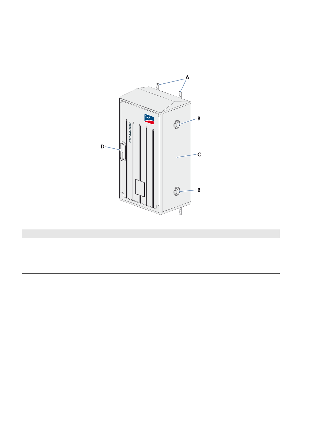
Figure2: Design of the Communit
Position Designation
A Mounting rails
BVent plugs
CEnclosure
D Switch cabinet lock
3.2 Type Label
The type label provides unique identification of the Communit. There are two type labels attached to the Communit.
The type labels are located on the right-hand inside panel and on the right-hand outside panel of the Communit. You will
find the following information on the type labels:
• Device type and option code
• Serial number
• Device-specific characteristics
You require the information on the type labels to use the Communit safely and when seeking customer support from the
SMA Service Line. The type labels must be permanently affixed to the Communit.
10 Communit-IA-A1-en-22 Installation Manual
Page 11
SMA Solar Technology AG 3 Product Description
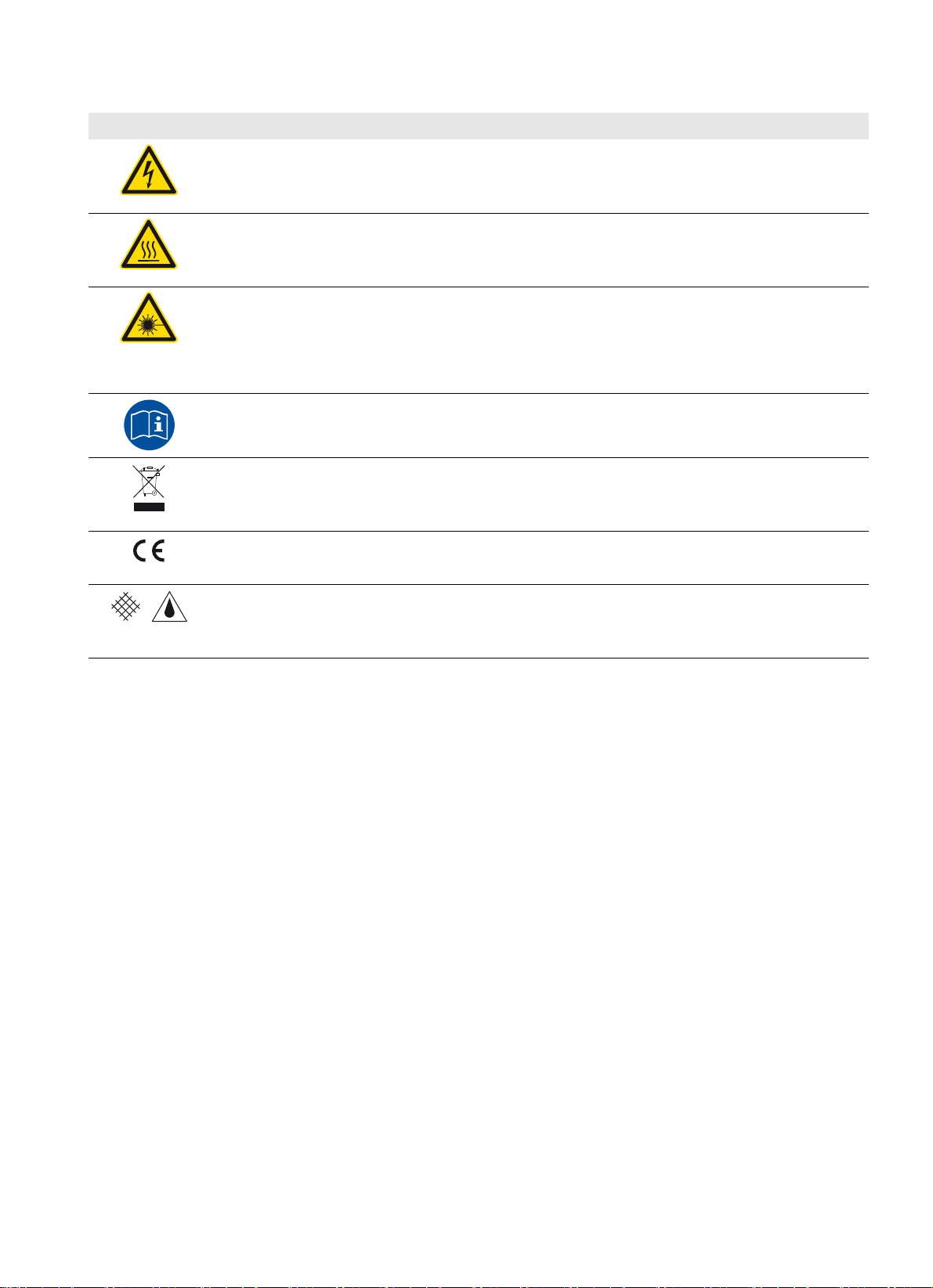
Symbols on the type label and in the Communit
Symbol Explanation
Danger to life due to high voltages
Danger of electric shock if work on the product is executed incorrectly. All work on the product must
be carried out by qualified persons only.
Risk of burns due to hot surfaces
The Communit can contain devices that can have a strongly increased surface temperature during
operation.
Laser radiation
The Communit contains LED or laser components in accordance with IEC 60825-1 (2003).
Laser class 1 - Class 1 Laser Product
Light emitting diode class 1 - Class 1 LED Product
Observe the documentation
Observe all documentation supplied with the product.
WEEE designation
Do not dispose of the Communit together with the household waste but only in accordance with the
locally applicable regulations for disposal for electronic waste.
CE marking
The product complies with the requirements of the applicable EU directives.
Degree of protection IP54
The Communit is protected against dust intrusion and water penetration. The Communit is suitable for
outdoor installation.
Installation Manual Communit-IA-A1-en-22 11
Page 12
4 Scope of Delivery SMA Solar Technology AG
4 Scope of Delivery
Check the scope of delivery for completeness and any externally visible damage. Contact your distributor if the scope of
delivery is incomplete or damaged.
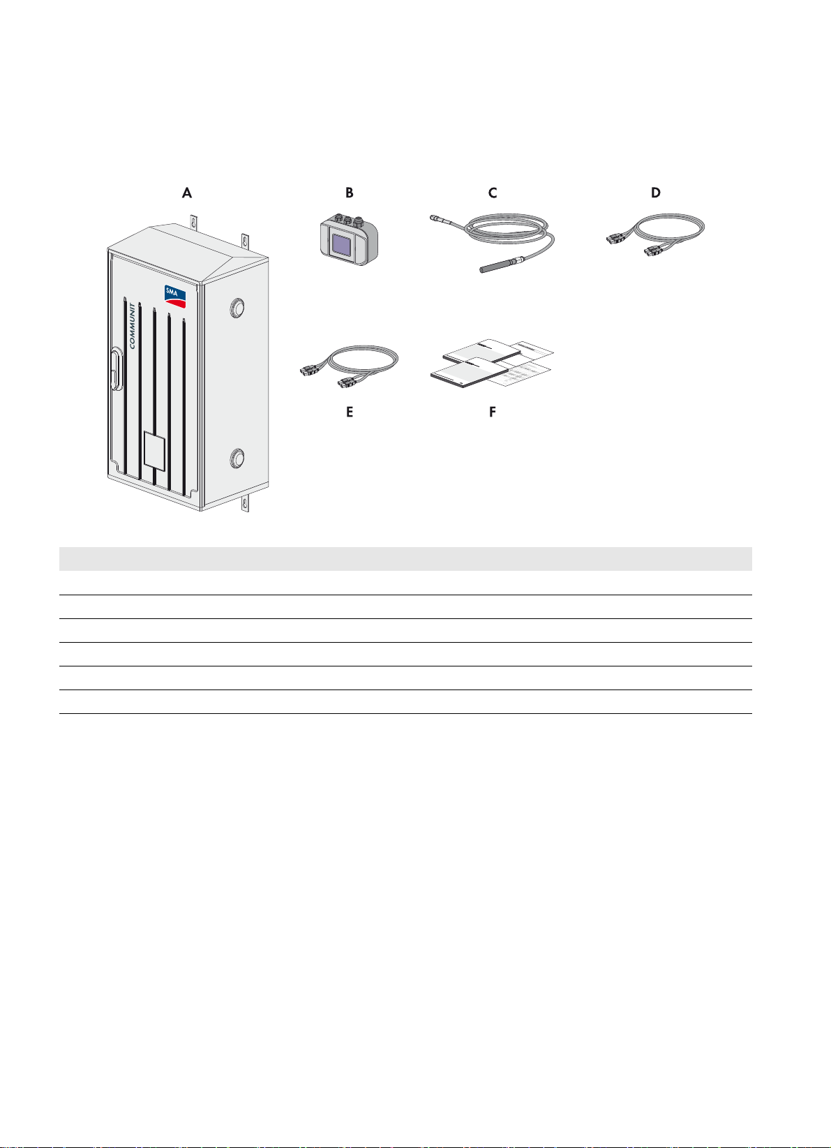
Wall Mounting Option
Figure3: Components for the wall mounting option
Position Quantity Designation
A 1 Communit
B 1 Sunny SensorBox*
C 1 Antenna*
D 2/4 SC/SC optical fiber patch cable, 0° polish 50/125 μm MMF*
E 2/4 SC/SC optical fiber patch cable, 0° polish 9/125 μm SMF*
F 1 Installation manual, circuit diagram, documentation of the installed devices**
*optional
** depending on the option ordered
12 Communit-IA-A1-en-22 Installation Manual
Page 13
SMA Solar Technology AG 4 Scope of Delivery
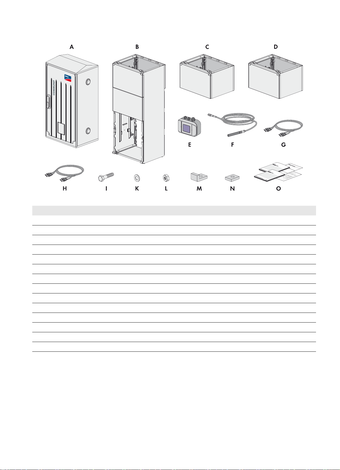
Base Mounting Option
Figure4: Components for the base mounting option
Position Quantity Designation
A 1 Communit
B1Base
C 1 First base extension
D 1 Second base extension
E 1 Sunny SensorBox*
F 1 Antenna*
G 2/4 SC/SC optical fiber patch cable 0° polish 50/125 μm MMF*
H 2/4 SC/SC optical fiber patch cable 0° polish 9/125 μm SMF*
I12Screw
K24Washer
L12Nut
M 8 Square washer with bracket
N4Square washer
O 1 Installation manual, circuit diagram, documentation of the installed devices**
*optional
** depending on the option ordered
Installation Manual Communit-IA-A1-en-22 13
Page 14
5 Mounting SMA Solar Technology AG
5 Mounting
5.1 Selecting the Mounting Location
Requirements for the mounting location:
☐ The ambient temperature is within the operating temperature range of ‒20°C to +50°C.
☐ The humidity is within the range of 5% to 95%.
☐ The altitude of the mounting location is below the maximum installation altitude of 4,000 m above sea level.
☐ The mounting location is in an industrial area.
☐ The mounting location must not block any escape routes.
☐The mounting location is clear and safely accessible at all times without the use of additional aids being necessary
(such as scaffolding or lifting platforms). Non-fulfillment of these criteria may restrict servicing.
☐ The mounting location is suitable for the weight and dimensions of the Communit.
☐ The mounting location is not exposed to direct solar irradiation.
☐ Mounting location is protected from rain as far as possible.
Overvoltage protection for installation altitudes above 2,000 m
For installation altitudes above 2,000 m, the overvoltage category is reduced to class II in accordance with
EN 50178.
• If necessary, install overvoltage protection modules. Thus, overvoltages of category III can be reduced to
overvoltages of category II.
Disconnection device
A disconnection device must be available for the installation work and commissioning in order to safely disconnect
the Communit from the voltage supply.
• Install a disconnection device close to the Communit. The disconnection device must be easily accessible.
Requirements for the bridging time in the event of voltage dips
The operators of PV systems are obliged to fulfill the requirements of the feed-in directives valid at the respective system
location.
The directives demand, depending on the system location, among other things the continued operation of the PV power
plant (including measures for grid stabilization) even in the event of short-term voltage dips.
In order to ensure this, the Communit is fitted as standard with a redundant electricity supply that ensures a bridging time
of 150 ms.
For further requirements, such as in unstable utility grids, SMA Solar Technology AG offers a redundant electricity supply
with an additional maintenance-free buffer module based on capacitors. A bridging time of at least six seconds is thus
ensured.
This support is not valid for the customer installation location.
14 Communit-IA-A1-en-22 Installation Manual
Page 15

SMA Solar Technology AG 5 Mounting
Observe permitted mounting position
Figure5: Permissible mounting positions of the Communit
Procedure:
• Mount the Communit in a permissible position.
5.2 Mounting the Communit on the Wall
Additionally required mounting material (not included in the scope of delivery):
☐ Four screws. Take the diameter of the holes in the mounting rails, the wall properties and the weight of the Communit
into account.
☐ If necessary, screw anchors and washers.
Figure6: Dimensions of the Communit for wall mounting
Installation Manual Communit-IA-A1-en-22 15
Page 16

5 Mounting SMA Solar Technology AG
&$87,21
Risk of injury due to inappropriate transport or mounting of the product
The product is heavy. If you try to move the product on your own, you run a risk of being injured. The maximum product
weight is 45 kg.
• Always have two persons transport and mount the product.
• Wear suitable personal protective equipment for all work on the device.
Procedure:
1. Mark the positions of the mounting holes on the wall.
2. Drill the mounting holes.
3. Insert screw anchors, if necessary.
4. Tighten the screws with washers in the screw anchors. The screws must protrude 10 mm from the wall.
5. Hang the Communit on the screws and align.
6. Tighten all screws.
7. Ensure that the Communit is firmly positioned.
8. Ensure that all connectors inside the Communit are firmly positioned.
16 Communit-IA-A1-en-22 Installation Manual
Page 17

SMA Solar Technology AG 5 Mounting
5.3 Mounting the Communit with Base
Figure7: Dimensions of the Communit for base mounting
Figure8: Dimensions of the pit for base mounting
Installation Manual Communit-IA-A1-en-22 17
Page 18
5 Mounting SMA Solar Technology AG
/05*$&
&$87,21
Risk of injury due to inappropriate transport or mounting of the product
The product is heavy. If you try to move the product on your own, you run a risk of being injured. The maximum product
weight is 45 kg.
• Always have two persons transport and mount the product.
• Wear suitable personal protective equipment for all work on the device.
Procedure:
1. Excavate a pit. Ensure that the burial depth for the base is 660 mm. Tip: the optimum burial depth is marked on the
sides of the base.
2. Place the base in the excavated pit. The side with the kick plate must be at the front.
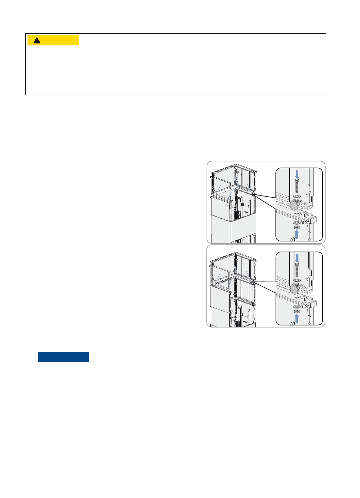
3. Attach the base extensions to the base:
• Place the first base extension on the base.
• Screw the first base extension into place at the four anchoring
points. Use the square washers with brackets.
• Place the second base extension on the first base extension.
• Screw the second base extension into place at the four
anchoring points. Use the square washers with brackets.
4. Lay all cables necessary for connecting the Communit. Observe all protective measures relating to the type of
cable-laying and the cable-laying specifications of the cable manufacturer.
Damage to the cables due to compaction of the ground
Heavy mechanical pressure during compaction of the ground can damage the cables.
• Protect the cables in the ground, for example by back-filling with sand or by using protective conduits.
5. Lead all necessary cables through the base and the base extensions. Take the length of the cables up to the
connection points into account (see Section6.1 "Overview of the Connection Area", page22).
6. Fill the pit with fine gravel up to the burial depth.
7. Compact the ground sufficiently.
8. Ensure that the base is firmly positioned.
9. Position the Communit on the base extension.
18 Communit-IA-A1-en-22 Installation Manual
Page 19

SMA Solar Technology AG 5 Mounting
10. Screw the Communit into place at the four anchoring points on the
base extension. Use the square washers.
11. Mount the lower kick plate on the first base extension and turn the
locking latches inwards.
12. Mount the upper kick plate under the Communit on the second
base extension and attach using two countersunk screws.
13. Ensure that all connectors inside the Communit are firmly positioned.
5.4 Determining the Optimum Mounting Location for the Antenna
If you have ordered the Communit with a UMTS router, the antenna included in the delivery must be mounted.
Lightning protection
Observe the local lightning protection regulations when mounting the antenna.
&$87,21
Radiation hazard due to high power density of the antenna
Electromagnetic radiation from the antenna can be damaging to health.
• Maintain a personal safety clearance of at least 4 cm from the antenna in operation.
Procedure:
1. Connect the antenna cable plug to the router (see Section6.4 "Connecting the Cables to the Network Switch and
Router", page29).
2. Select the mounting location of the antenna. Take the maximum cable length of 5 m into account.
3. Check whether the signal strength at the selected mounting location is sufficient:
• Log into the router (see Section7.2 "Configuring the Router", page33).
• Read off the signal strength in the field Signal strength.
The signal strength is sufficient if the field Signal strength is showing either Good or Very good.
Installation Manual Communit-IA-A1-en-22 19
Page 20

5 Mounting SMA Solar Technology AG
• Mount the antenna (see Section5.5 "Mounting the Antenna", page20).
The signal strength is insufficient if the field Signal strength is showing either Bad or Low.
• Select a different mounting location.
• Repeat step 3.
5.5 Mounting the Antenna
1. Mark the drill holes.
2. Drill holes with a diameter of 8 mm at the marked position.
3. Insert the screw anchors. Attach the bracket to the wall using the
screws.
4. Loosen the screw connection from the antenna.
5. Using the cable, guide the antenna sideways into the bracket.
6. Tighten the antenna cable gland (torque: 20 Nm). Hold on to the
antenna when doing this. This is in order to avoid twisting the cable.
7. Lay the cable to the router. If necessary, drill a hole in the station for feeding through the cable at a suitable place
and use either a protective conduit or cable channel.
5.6 Installing Your Own Optional Device
If the Communit is fitted with one or two customer installation locations, you can install your own devices in the Communit.
20 Communit-IA-A1-en-22 Installation Manual
Page 21

SMA Solar Technology AG 5 Mounting
Requirements:
☐ The device must be approved for operation at the mounting location, e.g. the device must have a valid declaration
of conformity in Europe.
☐ The device can be mounted on a top-hat rail.
☐ The device must have suitable dimensions for the available space (see the Technical Information "Communit").
☐ The customer device must be suitable for the connection to the voltage supply (see the Technical Information
"Communit").
Procedure:
• Mount each device on the top-hat rail.
Installation Manual Communit-IA-A1-en-22 21
Page 22
6 Electrical Connection SMA Solar Technology AG
6 Electrical Connection
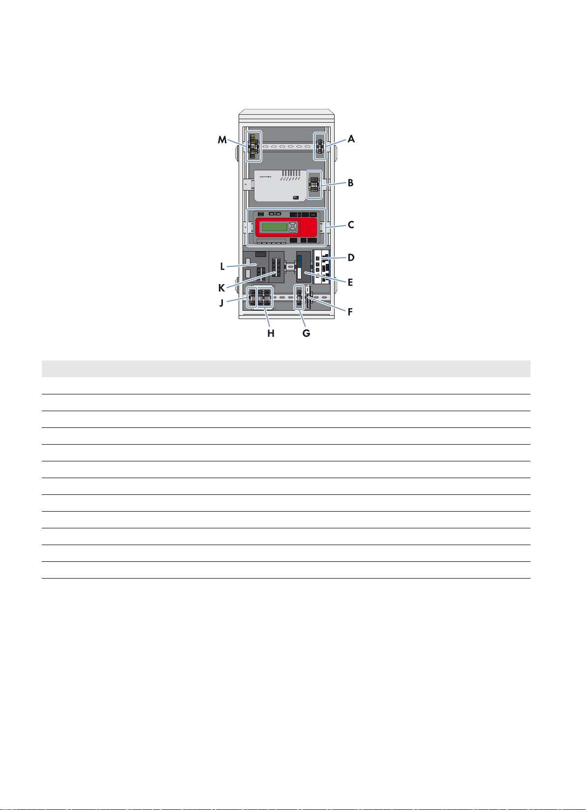
6.1 Overview of the Connection Area
Figure9: Installation locations and connections in the Communit (example)
Position Designation
A Connection of the customer device at installation location 1 to the DC voltage supply
B Connection of the customer device at installation location 2 to the DC voltage supply
C Connection to the Cluster Controller
D Patch panel
ERouter
F Connection to the I/O module
G Connection to the voltage supply terminals for triggering the digital inputs
H Connection of the Sunny SensorBox
J Terminal for the Communit voltage supply
K Network switch 1
L Network switch 2
M Connection of the customer device at installation location 1 to the AC voltage supply
22 Communit-IA-A1-en-22 Installation Manual
Page 23

SMA Solar Technology AG 6 Electrical Connection
/05*$&
6.2 Inserting the Cables into the Communication Distribution Unit
The individual devices in the communication distribution unit have been cabled. The cables are inserted through the cable
glands in the floor of the Communit.
Figure10: Cable glands in the floor of the Communit
Position Recommendations for cable entry
A For the supply voltage cable
B For the Sunny SensorBox cable
C For optical fibers
D For the cables of the Cluster Controller and the I/O module
E Reserve
F For the antenna cable
G For the network cables
H Reserve
External strain relief of the supply voltage cable
The cable for the Communit supply voltage must be led to the Communit with sufficient strain relief. The external cable
support rail is not included in the scope of delivery.
• Attach the supply voltage cable to an external cable support rail.
Unused cable glands
• Do not take the filler plugs out of the unused cable glands. The filler plugs serve as seals for the Communit.
Damage to the Communit due to moisture penetration
Moisture can penetrate the Communit through unsealed cable glands.
• Only remove the number of sealing rings from the rubber seal in the cable gland that corresponds to the cable
diameter.
Installation Manual Communit-IA-A1-en-22 23
Page 24

6 Electrical Connection SMA Solar Technology AG
Procedure:
1. If necessary, remove the Communit door.
2. Remove the filler plug from the cable gland.
3. Remove the rubber seal from the cable gland.
4. Adjust the rubber seal to the diameter of the cable to be inserted:
• Remove the appropriate number of sealing rings from the
rubber seal.
Cable diameter Number of sealing rings to be removed
4.5 mm to 5.0 mm 0
4.5 mm to 7.5 mm 1
7.0 mm to 10.0 mm 2
9.5 mm to 13.0 mm 3
5. Lead the cable through the swivel nut of the cable gland. Ensure that the thread of the swivel nut is facing upwards.
6. Insert the cable above the swivel nut sideways into the rubber seal.
7. Insert the rubber seal with the cable in the cable gland.
8. Cut the cable to length.
9. Tighten the cable gland.
6.3 Connecting the Cables to the Connecting Terminal Plates
6.3.1 Connecting Conductors to the Spring-Cage Terminal
Connect each conductor to the corresponding spring-cage terminal as follows.
Procedure:
1. Insert the screwdriver into the clamping contact of the spring-cage
terminal.
Connecting terminal plate Screwdriver size
X300, X460 3.5 x 0.5
X500 to X530 2.5 x 0.4
24 Communit-IA-A1-en-22 Installation Manual
Page 25

SMA Solar Technology AG 6 Electrical Connection
2. Insert the condu ctor into the terminal up to the stop. Make sure that
no insulation is clamped in the terminal.
3. Remove the screwdriver.
6.3.2 Connecting the Cable Shield Contact
Connect the cable shield contact of each required cable in accordance with the following procedure.
Procedure:
1. Dismantle the data cable.
2. Completely unscrew the knurled screw of the shield clamping bracket. This forces the clamping legs apart.
3. Remove the shield clamping bracket. For this, tip the shield clamping bracket lightly to the side.
4. Fit the cable shield onto the shield bus.
5. Place the shield clamping bracket on the shield bus and cable
shield.
6. Tighten the knurled screw (torque: 0.5 Nm).
6.3.3 Connecting the Communit Supply Voltage
Cable requirements:
☐ The cable for the supply voltage must also include a grounding conductor.
☐ Number of conductors: 3
☐ Conductor cross-section for rigid cables: 0.08 mm
2
to 4 mm
☐ Conductor cross-section for flexible cables: 0.14 mm2 to 2.5 mm
☐ The cable must be suitable for the local grid voltage.
2
2
Requirements:
☐ No supply voltage must be present.
☐ The cable for the supply voltage must be correctly inserted in the Communit (see Section6.2 "Inserting the Cables
into the Communication Distribution Unit", page23).
Installation Manual Communit-IA-A1-en-22 25
Page 26

6 Electrical Connection SMA Solar Technology AG
'$1*(5
Danger to life due to electric shock when voltage is present
Touching live components and cables results in death or serious injury due to electric shock.
• Install a disconnection device next to the Communit prior to installation work.
• Prior to cable connection, disconnect the supply voltage via the disconnection device.
• Observe the five safety rules when disconnecting the supply voltage:
– Disconnect the device from voltage sources.
– Ensure that the device cannot be reconnected.
– Ensure that no voltage is present.
– Ground and short-circuit the device.
– Cover and isolate any adjacent live components.
• Observe the circuit diagram and the clamp allocations included in the delivery when connecting the cables in the
communication distribution unit.
Procedure:
1. Dismantle the supply voltage cable.
2. Strip off the insulation of the conductors by 10 mm to 12 mm.
3. If you use bootlace ferrules, crimp the bootlace ferrules gas tight.
4. Connect the insulated conductors of the cable to the connecting terminal plate =CU-X300 (see Section6.3.1
"Connecting Conductors to the Spring-Cage Terminal", page24). Observe the correct allocation and ensure that
the insulation is not clamped.
Terminal Signal
1L
2N
3 Grounding conductor
5. Ensure that the cable is securely in place.
6.3.4 Connecting the Cables for the SMA Cluster Controller
The communication devices of the Communit have been cabled. For the SMA Cluster Controller, the connecting terminal
plates in the lower area of the Communit are omitted. Instead, the cables are connected directly to the
SMA Cluster Controller (for information on connecting the cables, see the SMA Cluster Controller documentation).
6.3.5 Connecting the Cables for the I/O Modules
For measuring and controlling the devices of your PV system, the Communit can be optionally equipped with an Ethernet
I/O module Moxa E1240 with eight analog channels or E1242 with four digital and four analog channels.
A 24 V
fuse.
Cable requirements:
☐ Maximum conductor cross-section for connection to the I/O module: 2.5 mm
☐ Conductor cross-section for rigid cables for connecting the sensors to the voltage supply terminal:
voltage supply is used to activate the digital inputs in the Communit. The connection is secured with a 315 mA
DC
2
0.08 mm
2
to 1.5 mm
2
☐ Conductor cross-section for flexible cables for connecting the sensors to the voltage supply terminal:
0.14 mm
2
to 1.5 mm
2
26 Communit-IA-A1-en-22 Installation Manual
Page 27

SMA Solar Technology AG 6 Electrical Connection
Procedure:
1. Strip off the conductor insulation of the cable by 10 mm.
2. If you use bootlace ferrules, crimp the bootlace ferrules gas tight.
3. Connect the insulated conductors of the cable to terminal -X700 or terminal -X701 (see Section6.3.1 "Connecting
Conductors to the Spring-Cage Terminal", page24). Observe the correct allocation and ensure that the insulation
is not clamped.
4. Connect the cables to the I/O module and configure the channels (see the documentation of the Ethernet I/O
module).
6.3.6 Connecting the RS485 Cable of the Sunny SensorBox
SMA Solar Technology AG recommends using COMCAB-type SMA data cables which are available in various lengths
as indoor and outdoor variants.
The communication devices of the Communit have been cabled. The Sunny SensorBox is connected to the connecting
terminal plate in the lower area of the Communit (see Section6.1 "Overview of the Connection Area", page22). You
will find further information on the RS485 communication bus in the RS485 cabling poster and in the Sunny SensorBox
documentation.
Cable requirements:
☐ The RS485 cable must be shielded.
☐ Cross-section of the RS485 cable: 2 x 2 x 0.14 mm
2
to 2 x 2 x 1.5 mm
2
☐ The conductors Data+ and Data‒ are a twisted pair.
☐ Conductors +12V and GND are a twisted pair.
Requirements:
☐ No supply voltage is present.
☐ The RS485 cable is correctly inserted into the Communit (see Section6.2 "Inserting the Cables into the
Communication Distribution Unit", page23).
☐ The shield of the RS485 cable is correctly fitted (see Section6.3.4 "Connecting the Cables for the
SMA Cluster Controller", page26).
Procedure:
1. Strip off the insulation of the conductors of the RS485 cable by 9 to 11 mm.
2. Connect the conductors to the connecting terminal plates -X520 and -X530 (see Section6.3.1 "Connecting
Conductors to the Spring-Cage Terminal", page24). Observe the correct allocation and ensure that the insulation
is not clamped.
Terminal Signal
Terminal 1 +12 V
Terminal 2 GND
Terminal 3 Data+
Terminal 4 Data‒
3. Terminate the RS485 communication bus. Terminators must only be installed at the bus start and bus end.
4. Ensure that the RS485 cable is securely attached.
Installation Manual Communit-IA-A1-en-22 27
Page 28

6 Electrical Connection SMA Solar Technology AG
6.3.7 Connecting the Voltage Supply of Your Own Optional Devices
If the Communit is fitted with one or two customer installation locations, you can install your own devices in the Communit
and connect them to the voltage supply.
Cable requirements:
☐ Number of conductors for the AC voltage supply: 3
☐ Number of conductors for the DC voltage supply: 2
☐ Conductor cross-section for rigid cables: 0.14 mm
2
to 1.5 mm
☐ Conductor cross-section for flexible cables: 0.14 mm2 to 1.5 mm2 (with bootlace ferrule: 0.14 mm2 to 1.0 mm2)
☐ The cable for the AC supply voltage must also include a grounding conductor.
☐ The electric strength of the cable must be suitable for the voltage present on site.
Requirements:
☐ The current and power consumption of the customer devices must not exceed the power reserve of the Communit
(see the Technical Information "Communit").
☐ No supply voltage must be present.
☐ The cable must be correctly inserted in the Communit (see Section6.2 "Inserting the Cables into the Communication
Distribution Unit", page23).
2
Connecting the Device at Installation Location 1
1. Strip off the conductor insulation of the cable by 8 mm.
2. If you are using bootlace ferrules, crimp them.
3. If you are using the AC voltage supply, connect the insulated conductors to the plugs of connecting terminal plate
-X320 (see Section6.3.1 "Connecting Conductors to the Spring-Cage Terminal", page24). Observe the correct
allocation and ensure that the insulation is not clamped.
Terminal Signal
1L
2N
3 Grounding conductor
4. Insert the plug into the terminals.
5. If you are using the DC voltage supply, connect the insulated conductors to the plug of the connecting terminal plate
-X461 (see Section6.3.1 "Connecting Conductors to the Spring-Cage Terminal", page24). Observe the correct
allocation and ensure that the insulation is not clamped.
Terminal Signal
1+24 VDC
20 VDC
28 Communit-IA-A1-en-22 Installation Manual
Page 29

SMA Solar Technology AG 6 Electrical Connection
6. Insert the plug into the terminals.
7. Ensure that the supply voltage cable is securely positioned.
Connecting the Device at Installation Location 2
1. Strip off the conductor insulation of the cable by 8 mm.
2. If you are using bootlace ferrules, crimp them.
3. Connect the insulated conductors to the connecting terminal plate -X420 (see Section6.3.1 "Connecting
Conductors to the Spring-Cage Terminal", page24). Observe the correct allocation and ensure that the insulation
is not clamped.
Terminal Signal
1 +24 VDC
20 VDC
4. Insert the plug into the terminals.
5. Ensure that the supply voltage cable is securely positioned.
6.4 Connecting the Cables to the Network Switch and Router
6.4.1 Connecting the Network Cables to the Network Switch
Network settings prior to connection
The devices installed in the Communit are delivered with a standard configuration. This can therefore lead to IP
address conflicts when two or more Communits are used.
• If there is more than one Communit in the PV system, change the IP addresses of the devices in all Communits
except one before connecting to the network (see Section7 "Commissioning the Communit", page33).
Requirement:
☐ If you use more than one Communit in the PV system, the devices of all Communits must have different IP addresses
(see Section7 "Commissioning the Communit", page33).
Procedure:
• Connect the network cables to the network switch.
Installation Manual Communit-IA-A1-en-22 29
Page 30

6 Electrical Connection SMA Solar Technology AG
6.4.2 Connecting the Cable to the Router
Requirements:
☐ The antenna cable must be correctly inserted in the Communit (see Section6.2 "Inserting the Cables into the
Communication Distribution Unit", page23).
Procedure:
• Connect the antenna cable to the router.
6.5 Splicing and Connecting the Optical Fiber
Additionally required material (not included in the scope of delivery):
☐ Connection fibers (optical fiber pigtails) of the appropriate glass fiber type with SC plugs
Requirements:
☐ The patch panel and the network switches must be suitable for the selected type of optical fiber.
☐ The optical fibers must be correctly inserted in the Communit (see Section6.2 "Inserting the Cables into the
Communication Distribution Unit", page23).
&$87,21
Damage to eyes and skin due to visible and invisible laser radiation
The Communit contains class 1 LED or laser components in accordance with IEC 60825-1 (2003). Invisible laser
radiation, wave length 1,300 nm.
The laser beam appears at the end of the optical fiber.
• Do not look into the laser beam.
• Do not look at the laser beam using optical instruments.
• Do not point the laser beam at people.
/05*$&
Damage to optical fibers due to too tight bend radii
Overly bending or kinking will damage the optical fiber.
• Observe the minimum permissible bend radii of the optical fibers.
30 Communit-IA-A1-en-22 Installation Manual
Page 31

SMA Solar Technology AG 6 Electrical Connection
Procedure:
1. Insert the optical fibers into the patch panel from below and splice
using optical fiber pigtails (see the patch panel documentation).
Observe the maximum permissible tension and the minimum
permissible bend radii of the optical fibers.
2. Connect the patch panel to the network switch using the optical fiber patch cables included in the delivery (bend
radius: 100 mm). Observe the send and receive directions of the optical fiber nodes.
6.6 Connecting the Network Cable via the Keystone Jack
The modular patch panel enables the connection of copper cables and optical fiber cables. The module for the copper
cables contains four RJ45 keystone pin connectors that are used to connect the network cables via keystone jacks.
Procedure:
1. Dismantle the network cable by 30 mm.
2. Fold back the braided shielding.
3. Remove the foil shield from the insulated conductor pairs.
4. With the adhesive side facing the inside, attach the aluminum foil from the outside so that it is flush with the braided
shielding.
5. Lead the network cable into the cable organizer.
6. Insert the conductors into the slots of the cable organizer. Observe the appropriate color coding for the standard of
your choice.
Insulated conductor pair Insulated conductor color Contact -568A Contact -568B
1white/blue55
blue 4 4
2white/orange31
orange 6 2
3 white/green 1 3
green 2 6
4white/brown77
brown 8 8
7. Shorten protruding conductors.
Installation Manual Communit-IA-A1-en-22 31
Page 32

6 Electrical Connection SMA Solar Technology AG
8. Insert the cable organizer in the enclosure. Make sure that the
white arrow of the cable organizer is pointing towards the white
arrow on the enclosure.
☑ The cable organizer snaps into place.
9. Push the folding parts of the enclosure back together using a suitable pair of pliers (e.g. pipe wrench).
☑ The folding parts of the enclosure snap into place.
10. Secure the cable retainer of the enclosure with a cable tie.
11. Cut off the protruding end of the cable tie.
12. Connect the keystone jack to the network cable on the patch panel.
13. Use the patch cable to connect the patch panel to the network switch.
32 Communit-IA-A1-en-22 Installation Manual
Page 33
SMA Solar Technology AG 7 Commissioning the Communit
7 Commissioning the Communit
7.1 Information on Commissioning
Requirements for commissioning:
☐ The supply voltage is correctly connected and tested.
☐ Unused cable glands are closed via the sealing plugs included in the delivery.
☐ All cable glands are tightened and sealed.
The network settings of the communication devices deviate from the default settings of the respective manufacturer.
Network settings prior to connection to the network
The devices installed in the Communit are delivered with a standard configuration. This can therefore lead to IP
address conflicts when two or more Communits are used.
• If there is more than one Communit in the PV system, change the IP addresses of the devices in all Communits
devices except one before connecting to the network.
Labels with IP addresses
Labels with the factory set IP addresses are present on the communication devices.
• If you change the IP address of a communication device, make a note of the new IP address on the respective
label.
7.2 Configuring the Router
When delivered, the router is configured with default settings for the communication with a modem via the network
protocol "Point-to-Point-Protocol over Ethernet" (PPPoE). If your modem uses other network protocols, the router must be
configured differently. Contact your distribution partner or the SMA Service Line.
Login data
• IP address: 172.16.0.1
• Subnet mask: 255.255.0.0
• Password for the user group "installer": 1111
• Password for the user group "user": 0000
SIM card
• Before you insert the SIM card in the router, clean the SIM card using a lint-free cloth and alcohol.
• Only insert the SIM card into the router when the router is switched off.
Procedure when replacing the SIM card
When a different SIM card is inserted, the router addresses the SIM card with a stored PIN. If this PIN does not
correspond to the new SIM card, the SIM card is locked.
• Enter the new PIN and save before inserting the new SIM card in the router.
Procedure:
1. Connect the computer to the router.
2. Start web browser (e.g. Internet Explorer).
3. Enter the IP address of the router in the address bar and press the enter key.
4. Select [OK].
5. Select Connectivity Settings > Internet Settings in the menu.
Installation Manual Communit-IA-A1-en-22 33
Page 34

7 Commissioning the Communit SMA Solar Technology AG
6. Enter the data of your internet provider in the area Internet Settings:
• Ensure that the correct type of Internet connection is selected in the drop-down list of the field Internet Service.
•Select [Set].
• If you use UMTS/GPRS as Internet connection, enter the APN of the Internet provider in the field APN / Phone
Number.
• Enter the user name for Internet access in the field Username. The user name is provided by the Internet provider.
• Enter the password for Internet access in the field Password. The password is provided by the Internet provider.
• Re-enter the password for confirmation in the field Verify password.
•Select [SAVE].
7. If your SIM card is protected with a PIN, select Connectivity Settings > Modem Settings in the menu.
8. Activate the checkbox SIM-PIN.
9. Enter the PIN of the SIM card in the field PIN.
10. Re-enter the PIN for confirmation in the field Verify PIN.
11. Select [SAVE].
12. Activate the monitoring of the digital inputs 1/2 in order to allow an e-mail to be sent in the event of a redundant
power supply unit fault:
•Select I/O Settings in the menu.
• Activate the checkbox Activate.
• In the drop-down list Signal action, select the value Alarm - Send E-Mail.
• If necessary, enter the e-mail text in the field Message.
•Select [SAVE].
13. Restart the router:
•Select Home in the menu.
•Select [REBOOT].
☑ The router will save the set data and restart.
34 Communit-IA-A1-en-22 Installation Manual
Page 35

SMA Solar Technology AG 7 Commissioning the Communit
7.3 Configuring the Network Switch
The network settings of the network switch deviate from the default settings of the manufacturer.
Login data
• IP address of the first network switch: 172.16.1.91
• If the second network switch is available, IP address of the second network switch: 172.16.1.92
• Subnet mask: 255.255.0.0
• Gateway: 172.16.0.1
• Password for the user group "admin": private
Procedure:
1. Connect the computer to the network switch.
2. Start web browser (e.g. Internet Explorer).
3. Enter the IP address of the network switch into the address bar and press the enter key.
4. Select the user group in the drop-down list.
5. Enter the user group password.
6. Select [OK].
7. Select Basic settings > Network in the menu.
8. Enter the desired IP address in the field IP address.
9. Select [Set].
☑ The network switch will save the set data.
7.4 Commissioning the Sunny WebBox
Login data
IP address of the Sunny WebBox: 172.16.1.41
Subnet mask: 255.255.0.0
Procedure:
• Configure the Sunny WebBox (see the Sunny WebBox documentation).
Installation Manual Communit-IA-A1-en-22 35
Page 36

8 Communit Maintenance Work SMA Solar Technology AG
8 Communit Maintenance Work
8.1 Maintenance Interval
• Perform maintenance work on the Communit every 24 months.
8.2 Checking the Mounting Location and Installation of the Communit
• Ensure that the mounting location is easily accessible without the need of additional equipment.
• Ensure that the Communit is securely mounted.
8.3 Checking the Enclosure and Enclosure Interior
• Check whether the Communit enclosure is damaged or soiled.
If the enclosure is severely damaged, contact the SMA Service Line.
• Ensure that the enclosure is clean.
• Ensure that the vent plugs in the Communit enclosure are intact and clean.
• Ensure that the door lock is intact and clean.
• Check whether the surrounding seals on the door frames are intact.
If the seals are damaged, replace them.
• Ensure that all cable glands are tightly sealed.
8.4 Checking the Supply Voltage
• Check whether the power supply units are in operation.
If the LED on the redundancy module is glowing, the power supply units are in operation.
If the LED on the redundancy module is not glowing, contact the SMA Service Line.
36 Communit-IA-A1-en-22 Installation Manual
Page 37

SMA Solar Technology AG 9 Decommissioning
9 Decommissioning
9.1 Disassembling the Communit
Requirement:
☐ No supply voltage is present.
Procedure:
1. Open the Communit door.
2. Disconnect all router cables.
3. Disconnect all network switch cables.
4. If available, disconnect the optical fibers.
5. Disconnect all cables from the connecting terminal plate.
6. Loosen the cable glands.
7. Pull out all cables through the cable glands.
8. Disassemble the Communit.
9.2 Disposing of the Communit
• Dispose of the Communit in accordance with the applicable disposal regulations for electronic waste.
Installation Manual Communit-IA-A1-en-22 37
Page 38

10 Troubleshooting SMA Solar Technology AG
10 Troubleshooting
Symptom Cause and corrective measure
No system communication Configuration error
Corrective measure:
• Ensure that all communication devices for the PV system network are correctly
configured (see information on IP address allocation in the Technical Information
"Plant Communication in Large-Scale PV Power Plants" at www.SMA.de).
Cabling error in the RS485 cable
Corrective measure:
• Ensure that the RS485 cable is connected correctly (see Section 6.3 and the poster
"RS485 Cabling Plan").
Error in the patch cable connection
Corrective measure:
• Ensure that the send and receive direction of the optical fiber nodes is correct.
Communication disturbance Unsuitable antenna mounting location
Corrective measure:
• Determine the optimum mounting location for the antenna (see Section5.4
"Determining the Optimum Mounting Location for the Antenna", page19).
38 Communit-IA-A1-en-22 Installation Manual
Page 39
SMA Solar Technology AG 11 Technical Data
11 Technical Data
Enclosure
Outdoor installation Shaded
Base mounting*
Yes
Wall mounting* Yes
Material Fiberglass-reinforced polyester
Color RAL 7035
Lock cylinder**
*optional
** prepared for customer mounting of a profile half-cylinder
Double-bit key for switch cabinet
Mechanical Data of the Enclosure without Base
Width x height x depth 427 mm x 868 mm x 345 mm
Weight*
* depending on the option ordered
38 kg to 45 kg
Mechanical Data of the Enclosure with Base
Width x height x depth 427 mm x 2,032 mm x 340 mm
Depth 660 mm
Weight*
38 kg to 45 kg
* depending on the option ordered
Option-Dependent Features
Maximum number of DSL/GSM/GPRS/UMTS routers*
1
Maximum number of Ethernet routers 1
Sunny WebBox with Sunny SensorBox 1 each
Maximum number of SMA Cluster Controllers 1
Maximum number of Ethernet network switches 2
Maximum number of patch panels**
1
Maximum number of Ethernet I/O modules 1
* including external antenna
** including splice cassette for optical fiber module
Ethernet I/O Module Moxa ioLogik E1240
Number of analog channels 8
Maximum conductor cross-section for connection to the I/O
2.5 mm
module
Conductor cross-section for connecting sensors to the voltage
0.14 mm2 to 1.5 mm
supply terminal
2
2
Installation Manual Communit-IA-A1-en-22 39
Page 40

11 Technical Data SMA Solar Technology AG
Ethernet I/O Module Moxa ioLogik E1242
Number of analog channels 4
Number of digital channels 4
Configurable digital inputs/outputs 4
Maximum conductor cross-section for connection at I/O
0.14 mm
2
to 1.5 mm
2
module
Analog Inputs of the I/O Modules Moxa ioLogik E1240 and E1242
Type Differential input
Resolution 16 bit
I/O mode Voltage/current
Input voltage range 0 V
Accuracy at 25°C / at –10°C to +60°C /
to 10 VDC / 0 mA to 20 mA / 0 mA to 20 mA
DC
±0.1% FSR / ±0.3% FSR / ±0.5% FSR
at –40°C to +75°C
Digital Inputs of the I/O Module Moxa ioLogik E1242
Sensor type Potential-free contact / wet contact (NPN or PNP)
I/O mode Digital input or event counter
Potential-free contact On: Short circuit to ground / Off: No-load operation
Wet contact NPN (DI to ground) On: 0 V
Wet contact PNP (DI to ground) Off: 0 V
to 3 VDC / Off: 10 VDC to 30 VDC
DC
to 3 VDC / On: 10 VDC to 30 V
DC
DC
Number of inputs per COM 4
Digital Outputs of the I/O Module Moxa ioLogik E1242
Type Sink
I/O mode Digital output or pulse output
Pulse output frequency 500 Hz
Overvoltage protection 45 V
DC
Overcurrent protection 2.6 A (4 channels at 650 mA)
Overtemperature protection minimum 150°C / typical 175°C
Current load 200 mA
Option-Dependent Interfaces
Communication DSL / GSM / GPRS / EDGE / UMTS / Ethernet /
Speedwire / RS485 communication
Grid Connection
Nominal voltage 100 V to 240 V
Supply voltage 24 V
Frequency 50 Hz/60 Hz
40 Communit-IA-A1-en-22 Installation Manual
Page 41

SMA Solar Technology AG 11 Technical Data
Grid Connection
Nominal current 1.6 A to 0.7 A
Maximum back-up fuse 16.0 A
Type of connection* Spring-cage terminals
Conductor cross-section for flexible cables 0.14 mm
2
to 2.5 mm
Conductor cross-section for rigid cables 0.08 mm2 to 4 mm
* L, N and PE connection
2
2
Grid Connection of the Optional Customer Device at Installation Location 1
Voltage supply 230 V
Maximum power consumption at 230 V
Maximum power consumption at 24 V
DC
AC
depending on the option
Type of connection X-COM
Conductor cross-section 0.14 mm
24 V
AC /
DC
20 W
®
plug
2
to 1.5 mm2 /
with bootlace ferrule 0.14 mm2 to 1.0 mm
Grid Connection of the Optional Customer Device at Installation Location 2
Voltage supply 24 V
Maximum power consumption at 24 V
DC
depending on the option
Type of connection X-COM
Conductor cross-section 0.14 mm
with bootlace ferrule 0.14 mm
DC
®
plug
2
to 1.5 mm2 /
2
Connection of the Sunny SensorBox
Type of connection Spring-cage terminals
Number of insulated conductors and cable cross-section 2 x 2 x 0.14 mm
2
to 2 x 2 x 1.5 mm
to 1.0 mm
2
2
2
Degree of Protection and Ambient Conditions
Degree of protection*
IP54
Permissible ambient temperatures –20°C to +50°C
Relative humidity**
Pollution degree***
Maximum altitude above mean sea level, MSL****
* as per EN 60529
** non-condensing
*** as per DIN EN 50178:1997
**** For installation altitudes above 2,000 m, the overvoltage category is reduced to class II.
5% to 95%
2
4,000 m
Installation Manual Communit-IA-A1-en-22 41
Page 42

12 Contact SMA Solar Technology AG
12 Contact
If you have technical problems concerning our products, please contact the SMA Service Line. We require the following
information in order to provide you with the necessary assistance:
• Communit serial number
•Article number
Australia SMA Australia Pty Ltd.
Sydney
Toll free for Australia: 1800 SMA AUS
(1800 762 287)
International: +61 2 9491 4200
Argentina
Brasil
Chile
Perú
Danmark
Deutschland
Österreich
Schweiz
SMA South America SPA
Santiago
+562 2820 2101
SMA Solar Technology AG
Niestetal
SMA Online Service Center:
www.SMA.de/Service
Sunny Boy, Sunny Mini Central,
Sunny Tripower: +49 561 9522-1499
Monitoring Systems
(Kommunikationsprodukte): +49 561
9522-2499
Fuel Save Controller (PV-Diesel Hybridsysteme): +49 561 9522-3199
Sunny Island, Sunny Backup,
Hydro Boy: +49 561 9522-399
Sunny Central: +49 561 9522-299
Belgien
Belgique
België
Luxemburg
Luxembourg
Nederland
Česko
Magyarország
Polska
România
Slovensko
France SMA France S.A.S.
SMA Benelux BVBA/SPRL
Mechelen
+32 15 286 730
SMA Central & Eastern Europe s.r.o.
Praha
+420 235 010 417
Lyon
Sunny Boy, Sunny Mini Central,
Sunny Tripower : +33 472 09 04 40
Monitoring Systems :
+33 472 09 04 41
Sunny Island : +33 472 09 04 42
Sunny Central : +33 472 09 04 43
España
Portugal
South Africa SMA Solar Technology
Italia SMA Italia S.r.l.
42 Communit-IA-A1-en-22 Installation Manual
SMA Ibérica Tecnología Solar, S.L.U.
Barcelona
+34 935 63 50 99
South Africa Pty Ltd.
Centurion (Pretoria)
08600 SUNNY (08600 78669)
International: +27 (12) 622 3000
Milano
+39 02 8934-7299
India SMA Solar India Pvt. Ltd.
Mumbai
+91 22 61713888
Ελλάδα
Κύπρος
Kıbrıs
България
United Kingdom SMA Solar UK Ltd.
SMA Hellas AE
Αθήνα
801 222 9 222
International: +30 212 222 9 222
Milton Keynes
+44 1908 304899
Page 43

SMA Solar Technology AG 12 Contact
!
SMA Solar (Thailand) Co., Ltd.
+66 2 670 6999
SMA Middle East LLC
+971 2 234-6177
대한민국 SMA Technology Korea Co., Ltd.
서울
+82-2-520-2666
Other countries International SMA Service Line
Niestetal
Toll free worldwide:
00800 SMA SERVICE
(+800 762 7378423)
Installation Manual Communit-IA-A1-en-22 43
Page 44

SMA Solar Technology
www.SMA-Solar.com
 Loading...