

Page 1

SUNNY BO
Y
SMA COM GATEWAY
SMA
- +
10 - 30V
DC
X1
RS485
RS485
COMGW-10-IA-en-13 | Version 1.3ENGLISH
Installation Manual
SMACOM GATEWAY
Page 2

Legal Provisions
SMA Solar Technology AG
Installation ManualCOMGW-10-IA-en-132
Legal Provisions
The information contained in these documents is the property of SMA Solar Technology AG. No
part of this document may be reproduced, stored in a retrieval system, or transmitted, in any form or
by any means, be it electronic, mechanical, photographic, magnetic or otherwise, without the prior
written permission of SMA Solar Technology AG. Internal reproduction used solely for the purpose
of product evaluation or other proper use is allowed and does not require prior approval.
SMA Solar Technology AG makes no representations or warranties, express or implied, with
respect to this documentation or any of the equipment and/or software it may describe, including
(with no limitation) any implied warranties of utility, merchantability, or fitness for any particular
purpose. All such representations or warranties are expressly disclaimed. Neither SMA Solar
Technology AG nor its distributors or dealers shall be liable for any indirect, incidental, or
consequential damages under any circumstances.
The exclusion of implied warranties may not apply in all cases under some statutes, and thus the
above exclusion may not apply.
Specifications are subject to change without notice. Every attempt has been made to make this
document complete, accurate and up-to-date. Readers are cautioned, however, that product
improvements and field usage experience may cause SMA Solar Technology AG to make changes
to these specifications without advance notice, or per contract provisions in those cases where a
supply agreement requires advance notice. SMA Solar Technology AG shall not be responsible for
any damages, including indirect, incidental or consequential damages, caused by reliance on the
material presented, including, but not limited to, omissions, typographical errors, arithmetical errors
or listing errors in the content material.
SMA Warranty
You can download the current warranty conditions from the Internet at www.SMA-Solar.com.
Software licenses
You will find the software licenses for the installed software modules on the Internet at www.SMASolar.com.
Trademarks
All trademarks are recognized, even if not explicitly identified as such. Missing designations do not
mean that a product or brand is not a registered trademark.
SMA Solar Technology AG
Sonnenallee 1
34266 Niestetal
Germany
Tel. +49 561 9522-0
Fax +49 561 9522-100
www.SMA.de
Email: info@SMA.de
Status: 9/26/2018
Copyright © 2018 SMA Solar Technology AG. All rights reserved.
Page 3

Table of Contents
SMA Solar Technology AG
Installation Manual COMGW-10-IA-en-13 3
Table of Contents
1 Information on this Document................................................. 5
1.1 Validity........................................................................................................................ 5
1.2 Target Group.............................................................................................................. 5
1.3 Content and Structure of this Document ................................................................... 5
1.4 Levels of warning messages...................................................................................... 5
1.5 Symbols in the Document .......................................................................................... 6
1.6 Typographies in the document.................................................................................. 6
1.7 Designation in the document..................................................................................... 6
1.8 Additional Information............................................................................................... 6
2 Safety ........................................................................................ 8
2.1 Intended Use .............................................................................................................. 8
2.2 IMPORTANT SAFETY INSTRUCTIONS.................................................................... 8
3 Scope of Delivery ..................................................................... 10
4 Product Overview .................................................................... 11
4.1 SMA Com Gateway.................................................................................................. 11
4.2 LED Signals................................................................................................................. 13
4.3 Function Button........................................................................................................... 14
5 Mounting................................................................................... 15
5.1 Requirements for Mounting ....................................................................................... 15
5.2 Mounting the SMA Com Gateway........................................................................... 16
6 Connection ................................................................................ 19
6.1 Overview of the Connection Area............................................................................ 19
6.2 Connecting RS485 Devices....................................................................................... 19
6.3 Connecting the SMA Data Logger ........................................................................... 21
6.4 Connecting the Voltage Supply ................................................................................ 22
7 Commissioning ......................................................................... 25
7.1 Commissioning the SMA Com Gateway ................................................................. 25
7.2 Configuring the SMA Com Gateway....................................................................... 25
8 Troubleshooting........................................................................ 26
8.1 Updating the Firmware.............................................................................................. 28
9 Decommissioning the SMA Com Gateway............................ 30
Page 4

Table of Contents
SMA Solar Technology AG
Installation ManualCOMGW-10-IA-en-134
10 Technical Data .......................................................................... 31
11 Contact ...................................................................................... 32
12 EU Declaration of Conformity ................................................. 34
Page 5

1 Information on this Document
SMA Solar Technology AG
Installation Manual COMGW-10-IA-en-13 5
1 Information on this Document
1.1 Validity
This document is valid for:
• COMGW-10 (SMA Com Gateway) from firmware version 1.00.01
1.2 Target Group
The tasks described in this document must only be performed by qualified persons. Qualified
persons must have the following skills:
• Training in the installation and configuration of IT systems
• Knowledge of how an inverter works and is operated
• Training in how to deal with the dangers and risks associated with installing, repairing and
using electrical devices and installations
• Training in the installation and commissioning of electrical devices and installations
• Knowledge of all applicable laws, standards and directives
• Knowledge of and compliance with this document and all safety information
1.3 Content and Structure of this Document
This document describes the installation, commissioning and decommissioning of the product.
You will find the latest version of this document and further information on the product in PDF format
at www.SMA-Solar.com.
Illustrations in this document are reduced to the essential information and may deviate from the real
product.
1.4 Levels of warning messages
The following levels of warning messages may occur when handling the product.
DANGER
Indicates a hazardous situation which, if not avoided, will result in death or serious injury.
WARNING
Indicates a hazardous situation which, if not avoided, could result in death or serious injury.
CAUTION
Indicates a hazardous situation which, if not avoided, could result in minor or moderate injury.
NOTICE
Indicates a situation which, if not avoided, can result in property damage.
Page 6
1 Information on this Document
SMA Solar Technology AG
Installation ManualCOMGW-10-IA-en-136
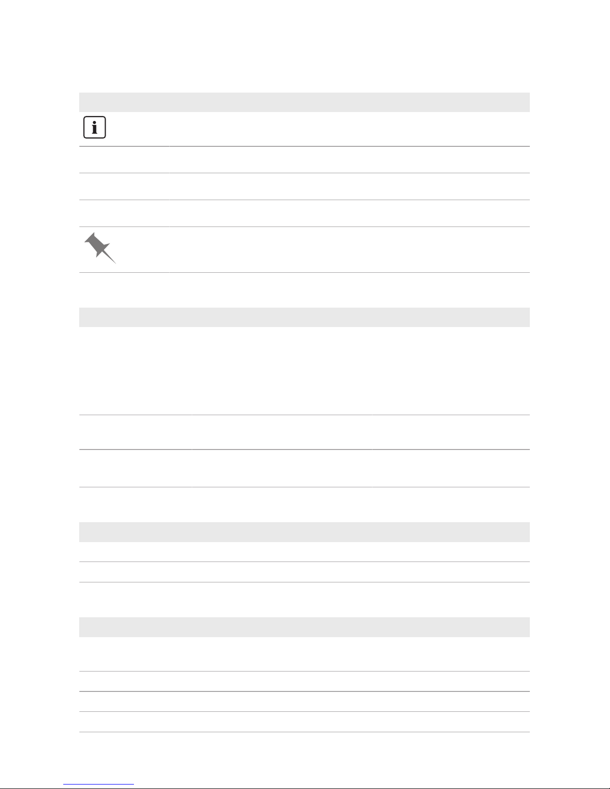
1.5 Symbols in the Document
Symbol Explanation
Information that is important for a specific topic or goal, but is not safety-relevant
☐
Indicates a requirement for meeting a specific goal
☑
Desired result
✖
A problem that might occur
Example
1.6 Typographies in the document
Typography Use Example
bold
• Messages
• Terminals
• Elements on a user interface
• Elements to be selected
• Elements to be entered
• Connect the insulated
conductors to the terminals
X703:1 to X703:6.
• Enter 10 in the field
Minutes.
>
• Connects several elements to be
selected
• Select Settings > Date.
[Button]
[Key]
• Button or key to be selected or
pressed
• Select [Enter].
1.7 Designation in the document
Complete designation Designation in this document
SMA Com Gateway SMAComGateway, product
SMA Speedwire fieldbus SMA Speedwire network, Speedwire
1.8 Additional Information
Title and information content Type of information
"PUBLIC CYBER SECURITY - Guidelines for a Secure PV System
Communication"
Technical information
"RS485 Cabling Plan" Installation Manual
"SMA CLUSTER CONTROLLER" Installation Manual
"SMA CLUSTER CONTROLLER" User Manual
Page 7

1 Information on this Document
SMA Solar Technology AG
Installation Manual COMGW-10-IA-en-13 7
Title and information content Type of information
"SMA COM GATEWAY - Compatibility and Application Options" Technical Information
"SMA DATA MANAGER M with SUNNY PORTAL powered by en-
nexOS"
Operating manual
"SMASPEEDWIRE FIELDBUS" Technical information
Page 8

2 Safety
SMA Solar Technology AG
Installation ManualCOMGW-10-IA-en-138
2 Safety
2.1 Intended Use
The SMA Com Gateway is a media and protocol converter that integrates PV systems and
components connected with each other via RS485 into the SMA Speedwire network.
In connection with a SMA data logger, the SMA Com Gateway must be operated with Speedwire
(e.g. SMA Data Manager M, SMAClusterController). The system data of all detected RS485
devices is forwarded from SMA Com Gateway via Speedwire to the SMA data logger. At the
same time, the SMA Com Gateway supports communication with up to 50 RS485 devices.
The USB interface of the SMA Com Gateway may only be used for firmware updates.
The product is designed for indoor use only.
All components must remain within their permitted operating ranges and their installation
requirements at all times.
Use this product only in accordance with the information provided in the enclosed documentation
and with the locally applicable laws, regulations, standards and directives. Any other application
may cause personal injury or property damage.
Alterations to the product, e.g. changes or modifications, are only permitted with the express written
permission of SMA Solar Technology AG. Unauthorized alterations will void guarantee and
warranty claims and in most cases terminate the operating license. SMA Solar Technology AG
shall not be held liable for any damage caused by such changes.
Any use of the product other than that described in the Intended Use section does not qualify as the
intended use.
The enclosed documentation is an integral part of this product. Keep the documentation in a
convenient place for future reference and observe all instructions contained therein.
This document does not replace and is not intended to replace any local, state, provincial, federal
or national laws, regulations or codes applicable to the installation, electrical safety and use of the
product. SMA Solar Technology AG assumes no responsibility for the compliance or noncompliance with such laws or codes in connection with the installation of the product.
The type label must remain permanently attached to the product.
2.2 IMPORTANT SAFETY INSTRUCTIONS
SAVE THESE INSTRUCTIONS
This section contains safety information that must be observed at all times when working on or with
the product.
The product has been designed and tested in accordance with international safety requirements. As
with all electrical or electronical devices, there are residual risks despite careful construction. To
prevent personal injury and property damage and to ensure long-term operation of the product,
read this section carefully and observe all safety information at all times.
Page 9
2 Safety
SMA Solar Technology AG
Installation Manual COMGW-10-IA-en-13 9
WARNING
Danger to life due to electric shock
Under fault conditions, when working on the power supply circuit there may be dangerous
voltages present on the product.
• With permanently connected power supply units, ensure that there is a disconnection unit
(e.g. circuit breaker) present outside of the power supply unit.
• With pluggable power supply units, ensure that the outlet for the power supply unit is close
to the power supply unit.
• The disconnect unit and the outlet for the power supply unit must be freely accessible at all
times.
WARNING
Danger to life due to electric shock from touching a damaged or open power
supply unit
Lethal voltages are present in the conductive parts inside the power supply unit. Touching a
damaged or open power supply unit can cause a lethal electric shock.
• Only use the power supply unit indoors and in a dry environment; keep it away from liquids.
• If the enclosure or the power supply unit cable is damaged, disconnect the connection point
from voltage sources. Replace the power supply unit with a suitable new power supply unit.
• Never open the power supply unit.
WARNING
Danger of fire due to incorrect installation
• Have the product mounted, installed and commissioned only by qualified persons with the
appropriate skills.
• Never open the product.
NOTICE
Damage to the product due to moisture
The product is not splash-proof. Moisture can penetrate the product and damage it.
• Only use the product in a dry, indoor environment.
NOTICE
Damage to the product due to condensation
If the product is moved from a cold environment to a warm environment, condensation may form
in the product.
• When there is a large temperature difference, wait for the product to reach room
temperature before connecting to the voltage supply.
• Make sure the product is dry.
Page 10

3 Scope of Delivery
SMA Solar Technology AG
Installation ManualCOMGW-10-IA-en-1310
3 Scope of Delivery
Check the scope of delivery for completeness and any externally visible damage. Contact your
distributor if the scope of delivery is incomplete or damaged.
SM
A C
O
M
G
ATEWAY
- +
1
0 - 30V
D
C
X
1
R
S
4
8
5
RS485
SMA
A
C
B
DD
Figure 1: Components included in the scope of delivery
Position Quantity Designation
A 1 SMA Com Gateway
B 1 Two-pole plug
C 1 Six-pole plug
D 1 Quick Reference Guide
Page 11

4 Product Overview
SMA Solar Technology AG
Installation Manual COMGW-10-IA-en-13 11
4 Product Overview
4.1 SMA Com Gateway
The SMA Com Gateway is a media and protocol converter that integrates PV systems and
components connected with each other via RS485 into the SMA Speedwire network.
The main tasks of the SMAComGateway are:
• Communication with up to 50 participants of an RS485 bus
• Reading off, storing and making system data available to an SMADataLogger
• Forwarding parameters from the SMADataLogger to the connected RS485 devices
• Forwarding system control commands and system regulation commands to the connected
RS485 devices
SMA COM GATEWAY
X3
X2
X4
X5
RS485
RS485
A
E
D
A
D
C
B
F
−+
10-30V
DC
X1
RS4
85
SMA COM GATEWAY
RS485
A
A
K
I
H
G
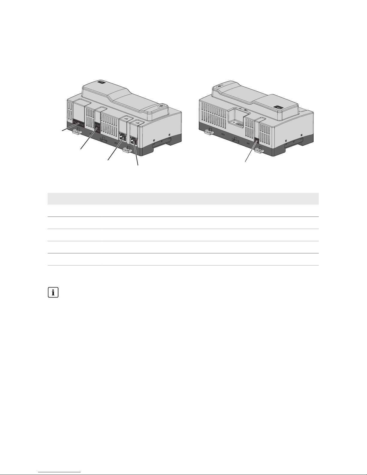
Figure 2: SMAComGateway design
Position Designation
A Press-out brackets for wall mounting
B Port for connecting the RS485 devices
C Reserved for future applications
D Network ports with status LEDs for connecting to the network
E Type label
The type label clearly identifies the product. You will require the information
on the type label to use the product safely and when seeking customer support from the SMAServiceLine. You will find the following information on the
type label:
• Device type (Model)
• Serial number (SerialNo.)
• Date of manufacture
• Device-specific characteristics
Page 12

4 Product Overview
SMA Solar Technology AG
Installation ManualCOMGW-10-IA-en-1312
Position Designation
F RS485 LED
The RS485 LED, together with the system LED, indicates the operating state of
the SMAComGateway (see Section4.2 "LED Signals", page13).
G System LED
The system LED, together with the RS485 LED, indicates the operating state of
the SMAComGateway (see Section4.2 "LED Signals", page13).
H Function button
I USB port for updates
K Jack for connecting the voltage supply
Symbols on the SMA Com Gateway and the Type Label
Symbol Explanation
USB
Function button
System LED
RS485 LED
Speedwire
The product is suitable for indoor installation.
CE marking
The product complies with the requirements of the applicable EU directives.
FCC designation
The product complies with the requirements of the applicable FCC standards.
Page 13

4 Product Overview
SMA Solar Technology AG
Installation Manual COMGW-10-IA-en-13 13
Symbol Explanation
CANICES-3(A)/
NMB-3(A)
IC marking
The product complies with the requirements of the applicable Canadian EMC
standards.
WEEE designation
Do not dispose of the product together with the household waste but in accor-
dance with the disposal regulations for electronic waste applicable at the in-
stallation site.
4.2 LED Signals
System- and RS485 LEDs
The LEDs indicate the operating state of the SMAComGateway.
System LED RS485 LED Explanation
Off Off No power supply or no boot up procedure.
Glowing orange Glowing orange Boot up procedure started.
Flashing orange Off Update procedure running.
Glowing red Off Boot up procedure running.
Glowing green Flashing orange Detection running.
Glowing green Flashing orange
and green in alter-
nation
Detection running. At least one RS485 device has been
detected.
Glowing green Off Normal operation. No data is being received from the
RS485 devices.
Function button has been pressed for longer than 15 sec-
onds.
Glowing green Flashing green Normal operation. Data is being received from the RS485
devices.
Glowing green Flashing red There is a system configuration error (e.g. too many
RS485 devices)
Flashing orange
and green in alternation
Glowing orange Function button has been pressed for less than 5 seconds.
Flashing orange
and green in alternation
Glowing green Function button has been pressed for between 5 and 10
seconds.
Page 14

4 Product Overview
SMA Solar Technology AG
Installation ManualCOMGW-10-IA-en-1314
System LED RS485 LED Explanation
Flashing orange
and green in alternation
Glowing red Function button has been pressed for between 10 and 15
seconds.
Glowing red (for
longer than 2 minutes)
Off Error
Network port LEDs
The colors of the network port LEDs and what each color indicates are not
standardized
The colors of the network port LEDs and what each color indicates are not standardized. The
colors used by SMA Solar Technology AG for the Link LED and the Activity LED and what
each color indicates may be different to those used in third-party products.
Figure 3: Network port LEDs
Position Designation Color Explanation
A Link LED Green Shows the network connection status.
B Activity LED Yellow Shows network connection activity.
4.3 Function Button
Depending on how long it is activated for, the function button performs the following functions:
• 1 to 5 seconds: renewed detection of RS485 devices
• 5 to 10 seconds: restarts the SMAComGateway
• 10 to 15 seconds: resets the SMAComGateway to the default settings
• Longer than 15 seconds: no effect
The length of time the function button has been activated for is indicated via LED signals (see
Section4.2 "LED Signals", page13).
Page 15

5 Mounting
SMA Solar Technology AG
Installation Manual COMGW-10-IA-en-13 15
5 Mounting
5.1 Requirements for Mounting
Requirements for the Mounting Location:
WARNING
Danger to life due to fire or explosion
Despite careful construction, electrical devices can cause fires.
• Do not mount the product in areas containing highly flammable materials or gases.
• Do not mount the product in potentially explosive atmospheres.
NOTICE
Damage due to dust and moisture ingress
Dust or moisture intrusion can damage the product and impair its functionality.
• The product is only suitable for indoor installation.
• The product may only be operated under the specified conditions.
☐ The mounting location must be suitable for the installation of the product.
☐ The mounting location must be suitable for the weight and dimensions of the product (see
Section10, page31).
☐ The mounting location must be inaccessible to children.
☐ The support surface must be suitable for mounting, e.g. concrete, masonry.
☐ The mounting location should be freely and safely accessible at all times without the need for
any auxiliary equipment (such as scaffolding or lifting platforms). Non-fulfillment of these
criteria may restrict servicing.
☐ The mounting location should not be exposed to direct solar irradiation.
☐ All ambient conditions must be met (see Section10, page31).
☐ The labelling on the product must be readable after installation.
Page 16

5 Mounting
SMA Solar Technology AG
Installation ManualCOMGW-10-IA-en-1316
Recommended clearances:
☐ There must be a clearance of 50mm above and below the SMAComGateway to other
objects.
Permitted Mounting Position:
☐ The product may only be mounted in a horizontal position.
Dimensions for Wall Mounting:
SMA COM GATEWAY
RS485
X3X2 X4 X5
X1
− +
10-30V
DC
RS485
108 mm
162 mm
98 mm
90 mm
104 mm
Figure 4: Dimensions for wall mounting
5.2 Mounting the SMAComGateway
There are two options for mounting the SMAComGateway:
• Mounting on a top-hat rail
• Mounting on a wall
Page 17

5 Mounting
SMA Solar Technology AG
Installation Manual COMGW-10-IA-en-13 17
Mounting the SMAComGateway on a Top-Hat Rail
Additionally required mounting material (not included in the scope of delivery):
☐ Top-hat rail (TH 35-7.5)
Requirement:
☐ The top-hat rail must be securely mounted.
Procedure:
1. Place the SMAComGateway onto the top-hat rail
from above and hook it in.
2
1
SMACOM GATEWAY
SMA
☑ The SMAComGateway snaps into place.
2. Ensure that the SMAComGateway is securely in place.
Mounting the SMAComGateway on a Wall
Additionally required mounting material (not included in the scope of delivery):
☐ 4 screws suitable for the support surface and the brackets. Do not use countersunk screws.
☐ Where necessary, 4 screw anchors suitable for the support surface and the screws.
Procedure:
1. Press the four brackets on the rear side of the
SMAComGateway outwards.
☑ The brackets snap into place.
2. Mark the drill holes using the brackets as a template.
3. Drill the holes and insert the screw anchors if necessary. Do not drill through the brackets.
Page 18

5 Mounting
SMA Solar Technology AG
Installation ManualCOMGW-10-IA-en-1318
4. Insert the screws through the brackets and tighten.
Do not damage the brackets.
SMACOM GATEWAY
SMA
5. Ensure that the SMAComGateway is securely in place.
Page 19
6 Connection
SMA Solar Technology AG
Installation Manual COMGW-10-IA-en-13 19
6 Connection
6.1 Overview of the Connection Area
SMA COM GATEWAY
X3
X2
X4
X5
RS485
RS485
X2
X5
X4
X3
−+
10-30V
DC
X1
R
S
4
8
5
SMA COM GATEWAY
RS485
X1
Figure 5: Overview of the connection area
Terminal Explanation
X1 Jack for connecting the voltage supply.
X2 Port for connecting the RS485 devices.
X3 Reserved for future applications.
X4 Network port with status LEDs for connecting to the SMA Speedwire network.
X5 Network port with status LEDs for connecting to the SMA Speedwire network.
6.2 Connecting RS485 Devices
Renewed detection after a replacement or addition
If you replace or add RS485 devices, you must detect the RS485 devices again. To do this,
press and hold the function button on the SMAComGateway using a sharp object (e.g.
paperclip) for between 1 and 5 seconds.
Cable requirements:
☐ Cross-section: at least 2x2x0.22mm² or at least 2x2x24AWG
☐ Shielded
☐ Twisted pair conductors
☐ UV resistant
☐ Maximum cable length across the entire RS485 bus: 1200 m
Page 20

6 Connection
SMA Solar Technology AG
Installation ManualCOMGW-10-IA-en-1320
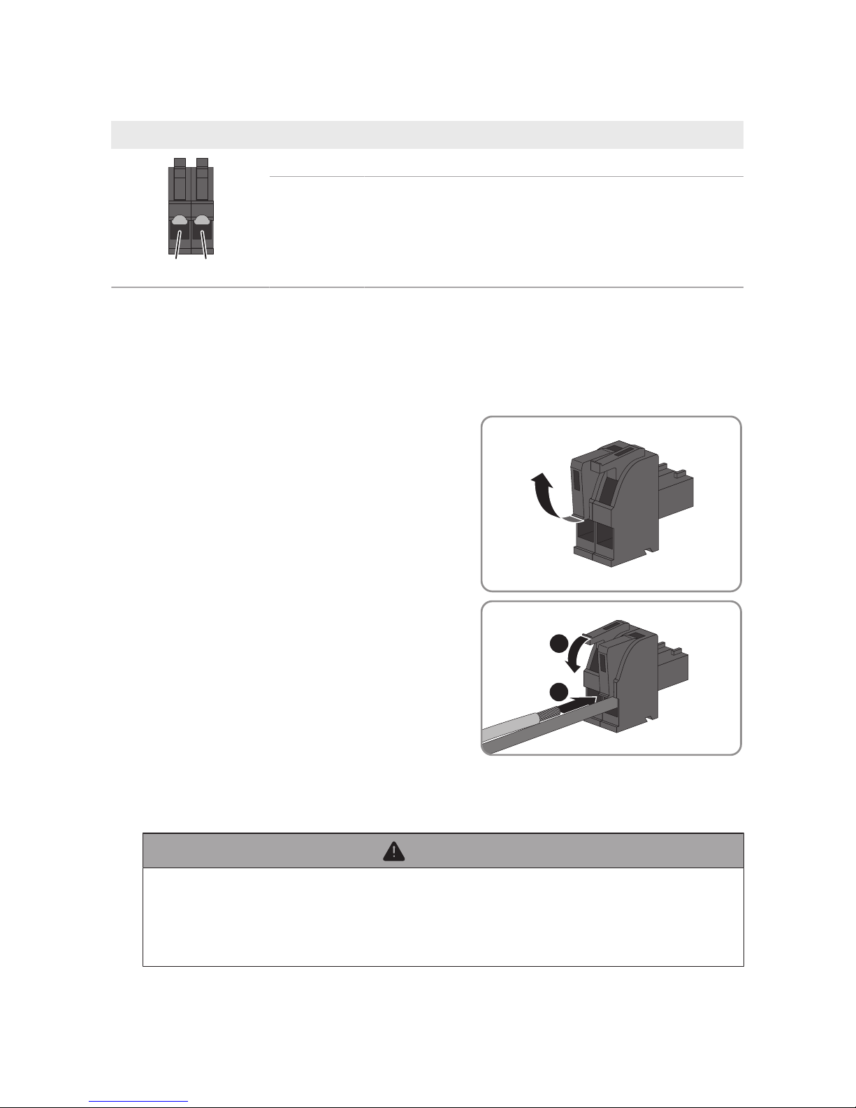
Plug assignment:
Plug Position Assignment
1
2
3
6
45
1 Data+ (D+)
2 Not assigned
3 Ground (GND)
4 Data- (D-)
5 Line termination (optional)
6 Line termination (optional)
Procedure:
1. Dismantle 40mm of the SMAComGateway end of the RS485 data cable.
2. Strip the shielding to the same length as the cable sheath.
3. Shorten unused insulated conductors flush with the cable sheath.
4. Strip off the conductor insulation by 6mm.
5. Release the conductor entries on the supplied sixpole plug.
6. Connect the RS485 data cable conductors to the
supplied six-pole plug. To do so, plug the
conductors into the conductor entries and close the
conductor entries. Observe the plug assignment.
1
2
7. If the SMAComGateway is at the end of the
RS485 bus, install a jumper wire as a line terminator
between pin 5 and pin 6 on the six-pole plug.
Page 21

6 Connection
SMA Solar Technology AG
Installation Manual COMGW-10-IA-en-13 21
8. Plug the six-pole plug into the port X2 on the
SMAComGateway.
X3
X2
X4
X5
R
S
4
8
5
RS485
RS485
6.3 Connecting the SMADataLogger
Interference in data transmission due to unshielded power cables
If unshielded power cables are used, they generate an electromagnetic field during operation
which may induce interference in network cables during data transmission.
• When laying network cables, observe the following minimum clearances to unshielded
energy cables:
– For installation without separating strip: at least 200mm
– For installation with aluminum separating strip: at least 100mm
– For installation with steel separating strip: at least 50mm
Additionally required material (not included in the scope of delivery):
☐ One network cable
Cable requirements:
The cable length and quality affect the quality of the signal. Observe the following cable
requirements:
☐ Cable type: 100BaseTx, from Cat5 with shielding S-UTP, F-UTP or higher
☐ Plug type: RJ45 of Cat5, Cat5e, Cat6 or Cat6a. Cat7 plugs cannot be used.
☐ Maximum cable length between two nodes when using patch cables: 50 m
☐ Maximum cable length between two nodes when using installation cables: 100 m
☐ UV-resistant for outdoor use
Procedure:
1. Plug the RJ45 plug of the network cable into the network port X4 or X5 until the RJ45 plug
snaps into place. The assignment of the network cables to the ports is not relevant, as the ports
constitute a switch function.
2. Connect the other end of the network cable to the network.
Page 22

6 Connection
SMA Solar Technology AG
Installation ManualCOMGW-10-IA-en-1322
6.4 Connecting the Voltage Supply
WARNING
Danger to life due to electric shock
Under fault conditions, when working on the power supply circuit there may be dangerous
voltages present on the product.
• With permanently connected power supply units, ensure that there is a disconnection unit
(e.g. circuit breaker) present outside of the power supply unit.
• With pluggable power supply units, ensure that the outlet for the power supply unit is close
to the power supply unit.
• The disconnect unit and the outlet for the power supply unit must be freely accessible at all
times.
NOTICE
Damage to the product due to condensation
If the product is moved from a cold environment to a warm environment, condensation may form
in the product.
• When there is a large temperature difference, wait for the product to reach room
temperature before connecting to the voltage supply.
• Make sure the product is dry.
Additionally required material (not included in the scope of delivery):
☐ 1 power supply unit
☐ 1 AC connection cable
☐ 1 connection cable for connecting the power supply unit to the SMAComGateway
Requirements for the power supply unit:
☐ Short-circuit current: <8A
☐ Nominal output power: 5W
☐ DC output voltage: 10V to 30V
☐ Compliance with the requirements on current sources with limited power in accordance with
IEC 60950
Requirements on the connection cable for connecting the power supply unit to the
SMAComGateway:
☐ Core cross-section: 0.2 to 1.5 mm²
☐ The cable must have at least two insulated conductors
☐ Maximum cable length: 3 m
Page 23
6 Connection
SMA Solar Technology AG
Installation Manual COMGW-10-IA-en-13 23
Plug assignment:
Plug Position Assignment
1
2
1 Input voltage 10to30VDC
2 Ground (GND)
Procedure:
1. Mount the power supply unit (see the manufacturer manual).
2. Connect the connection cable to the power supply unit (see the manufacturer manual). Make
a note of the insulated conductor colors and trim the unused insulated conductors back to the
cable sheath.
3. Release the conductor entries on the supplied twopole plug.
4. Connect the connection cable to the supplied twopole plug. To do so, plug the conductors into the
conductor entries and close the conductor entries.
Observe the plug assignment.
1
2
5. Trim unused insulated conductors flush with the cable sheath.
6. Plug the two-pole plug into the jack X1 on the SMAComGateway.
7. Connect the AC connection cable to the power supply unit (see the manufacturer manual).
8.
WARNING
Danger to life due to electric shock
Lethal voltages are present at the connection point of the utility grid.
• Disconnect the connection point from voltage sources and ensure that the connection
point is voltage-free.
Page 24

6 Connection
SMA Solar Technology AG
Installation ManualCOMGW-10-IA-en-1324
9. Connect the other end of the AC connection cable to the voltage supply.
10. Connect the connection point to the utility grid.
☑ The SMAComGateway starts detecting the RS485 devices (see Section7 "Commissioning",
page25). This process can take several minutes.
Page 25

7 Commissioning
SMA Solar Technology AG
Installation Manual COMGW-10-IA-en-13 25
7 Commissioning
7.1 Commissioning the SMA Com Gateway
Requirements:
☐ All RS485 devices must be in operation and connected correctly to the SMAComGateway
via the RS485 bus.
☐ The SMADataLogger must be in operation and connected correctly to the
SMAComGateway via the network.
☐ The voltage supply must be connected correctly to the SMAComGateway.
Procedure:
1. Check whether the System LED on the SMAComGateway is glowing green.
If the System LED is not glowing green, read the troubleshooting information (see Section8
"Troubleshooting", page26).
2. Check whether the SMAComGateway has been detected in the SMADataLogger.
If the SMAComGateway has not been detected, ensure that the network cable is connected
correctly.
If the problem persists, read the troubleshooting information(see Section8 "Troubleshooting",
page26).
3. Check whether all RS485 devices are being shown in the SMADataLogger.
If not all of the RS485 devices have been detected, read the troubleshooting information (see
Section8 "Troubleshooting", page26).
4. Add the SMAComGateway in the SMADataLogger and reenter the system password (see
SMADataLogger manual).
7.2 Configuring the SMAComGateway
You can configure the SMAComGateway. Configuration takes place via the SMADataLogger
user interface (see SMADataLogger manual). Parameters that are changed during a pending data
acquisition request will be considered with the next request. The following configuration options are
available:
• Setting the baud rate (1200 baud or 19200 baud). Renewed detection is necessary upon
completion.
• Setting the number of RS485 devices to be detected (maximum 50). Renewed detection is
necessary upon completion.
• Starting RS485 device detection.
• Restarting the SMAComGateway.
• Resetting the SMAComGateway to the default settings.
• Setting the IP configuration (DHCP or manual).
Page 26

8 Troubleshooting
SMA Solar Technology AG
Installation ManualCOMGW-10-IA-en-1326
8 Troubleshooting
Problem Cause and corrective measures
The SMADataLogger can
not find the SMAComGateway.
The network cable is not connected correctly.
Corrective measures:
• Ensure that the network cable is connected correctly and that
the network port Link LED is glowing.
The network cable or connector is defective or damaged.
Corrective measures:
• Replace the defective or damaged network cable or connector.
The SMADataLogger does not automatically assign an IP address
to the SMAComGateway.
Corrective measures:
• Ensure that DHCP is activated on the SMADataLogger.
or
• Assign a suitable static IP address to the SMAComGateway
via SMA Connection Assist or Sunny Explorer. You can obtain
the SMAConnectionAssist and SunnyExplorer software free
of charge at www.SMA-Solar.com.
Page 27

8 Troubleshooting
SMA Solar Technology AG
Installation Manual COMGW-10-IA-en-13 27
Problem Cause and corrective measures
Not all RS485 devices are
being detected.
Not all RS485 devices are in operation.
Corrective measures:
• Ensure that all RS485 devices are in operation.
Then perform a renewed RS485 device detection. To do this,
press and hold the function button on the SMAComGateway
using a sharp object (e.g. paperclip) for between 1 and 5
seconds.
There are too many RS485 devices in the system.
Corrective measures:
• Ensure that there are no more than 50 RS485 devices in the
system.
Then perform a renewed RS485 device detection. To do this,
press and hold the function button on the SMAComGateway
using a sharp object (e.g. paperclip) for between 1 and 5
seconds.
or
• Ensure that the value set in the SMAComGateway for the
number of RS485 devices to be detected is not too low.
Then perform a renewed RS485 device detection. To do this,
press and hold the function button on the SMAComGateway
using a sharp object (e.g. paperclip) for between 1 and 5
seconds.
The baud rate of one or more RS485 devices has been configured
incorrectly.
Corrective measures:
• Ensure that all baud rates in the system are in accordance with
the SMAComGateway.
Then perform a renewed RS485 device detection. To do this,
press and hold the function button on the SMAComGateway
using a sharp object (e.g. paperclip) for between 1 and 5
seconds.
Page 28

8 Troubleshooting
SMA Solar Technology AG
Installation ManualCOMGW-10-IA-en-1328
Problem Cause and corrective measures
The device data is being displayed incorrectly in the
SMADataLogger
One or more RS485 devices have been replaced or added.
Corrective measures:
• Perform a renewed RS485 device detection. To do this, press
and hold the function button on the SMAComGateway using
a sharp object (e.g. paperclip) for between 1 and 5 seconds.
One or more RS485 devices have been configured.
Corrective measures:
• Perform a renewed RS485 device detection. To do this, press
and hold the function button on the SMAComGateway using
a sharp object (e.g. paperclip) for between 1 and 5 seconds.
Then restart the SMADataLogger (see SMADataLogger
manual).
8.1 Updating the Firmware
There are two ways to update the SMAComGateway firmware:
• Updating the firmware automatically via SMADataLogger
• Updating the firmware at the SMAComGateway via USB flash drive
Automatically Updating the Firmware via SMADataLogger
• Set automatic firmware updating in the SMADataLogger (see SMADataLogger manual).
Updating the Firmware at the SMAComGateway via USB Flash Drive
Requirements:
☐ A USB flash drive with maximum 32GB storage capacity and file system FAT32 must be
available.
☐ The SMAComGateway must be in operation.
Procedure:
1. Create an "UPDATE" folder on the USB stick.
2. Save the update file with the desired firmware in the "UPDATE" folder on the USB flash drive.
The update file is, for example, available for download on the SMAComGateway product
page at www.SMA-Solar.com.
3. The update file will be renamed as "update.up2".
Page 29

8 Troubleshooting
SMA Solar Technology AG
Installation Manual COMGW-10-IA-en-13 29
4. Plug the USB flash drive into the USB port on the SMAComGateway.
☑ The System LED flashes orange during the firmware update. This process can take several
minutes.
☑ Once the firmware has been updated successfully, the System LED glows green
continuously.
✖ The SYSTEM LED is not glowing green continuously?
• Update the firmware again.
5. Pull the USB flash drive out of the USB port on the SMAComGateway.
Page 30

9 Decommissioning the SMAComGateway
SMA Solar Technology AG
Installation ManualCOMGW-10-IA-en-1330
9 Decommissioning the SMAComGateway
1.
WARNING
Danger to life due to electric shock
Lethal voltages are present at the connection point of the utility grid.
• Disconnect the connection point from the utility grid using the separator (e.g. circuit
breaker).
• Pull the two-pole power supply unit plug out of the jack X1 on the
SMAComGateway.
2. Release the RJ45 network cable plug and pull out of the network port X4 or X5 on the
SMAComGateway.
3. Pull the six-pole plug for connecting the RS485 devices out of the port X2 on the
SMAComGateway.
4. Remove the SMAComGateway:
• If mounted on a top-hat rail, unhook the
SMAComGateway from the top-hat rail. To
do so, tilt the lower edge of the
SMAComGateway forwards and remove the
SMAComGateway upwards out of the tophat rail.
SMA COM GATEWAY
SMA
2
1
• If mounted on a wall, remove the screws from the brackets and remove the
SMAComGateway.
5. If the SMAComGateway is to be disposed of, dispose of the SMAComGateway in
accordance with the locally applicable disposal regulations for electronic waste.
Page 31

10 Technical Data
SMA Solar Technology AG
Installation Manual COMGW-10-IA-en-13 31
10 Technical Data
Communication
RS485 devices Maximum 50 devices, 1200 or 19200 baud
SMADataLogger Speedwire, 10 / 100 Mbit/s
Connections
Voltage supply 2-pole connection, MINI COMBICON
RS485 6-pole connection, MINI COMBICON
SMADataLogger / network (LAN) 2 x RJ45 switched, 10BaseT / 100BaseT
USB 1 x USB 2.0, type A
Voltage Supply
Voltage supply External power supply unit
Input voltage range 10V to 30V
Power consumption Type 4 W
Ambient Conditions in Operation
Ambient temperature -20°C to +60°C
Max. permissible value for relative humidity
(non-condensing)
5% to 95%
Maximum operating altitude above mean sea
level (MSL)
3000 m
Degree of protection IP20
General Data
Dimensions (W x H x D) 161.1mmx 89.7mmx 67.2mm
Weight 203 g
Mounting location Indoors
Mounting type Top-hat rail mounting / wall mounting
Status display LEDs for system-, RS485- and Ethernet status
Equipment
Warranty 2 years
Certificates and approvals www.SMA-Solar.com
Page 32

11 Contact
SMA Solar Technology AG
Installation ManualCOMGW-10-IA-en-1332
11 Contact
If you have technical problems with our products, please contact the SMAServiceLine. The
following data is required in order to provide you with the necessary assistance:
• Device type
• Serial number
• Firmware version
• Event message
• Device type, serial number and firmware version of the SMADataLogger (if available)
Deutschland
Österreich
Schweiz
SMA Solar Technology AG
Niestetal
Sunny Boy, Sunny Mini Central,
SunnyTripower:
+495619522‑1499
Monitoring Systems
(Kommunikationsprodukte):
+495619522‑2499
Fuel Save Controller
(PV-Diesel-Hybridsysteme):
+495619522-3199
Sunny Island, Sunny Boy Storage, Sunny Backup:
+495619522-399
Sunny Central, Sunny Central
Storage:
+495619522-299
SMA Online Service Center:
www.SMA-Service.com
Belgien
Belgique
België
Luxemburg
Luxembourg
Nederland
SMA Benelux BVBA/SPRL
Mechelen
+3215286 730
SMA Online Service Center:
www.SMA-Service.com
Česko
Magyarország
Slovensko
SMA Service Partner TERMS
a.s.
+4203876 85 111
SMA Online Service Center:
www.SMA-Service.com
Türkiye SMA Service Partner DEKOM
Ltd. Şti.
+90 24 22430605
SMA Online Service Center:
www.SMA-Service.com
France SMA France S.A.S.
Lyon
+33 472 22 97 00
SMA Online Service Center :
www.SMA-Service.com
Ελλάδα
Κύπρος
SMA Service Partner AKTOR
FM.
Αθήνα
+30 210 8184550
SMA Online Service Center:
www.SMA-Service.com
España
Portugal
SMA Ibérica Tecnología Solar,
S.L.U.
Barcelona
+34935635099
SMA Online Service Center:
www.SMA-Service.com
United Kingdom
SMA Solar UK Ltd.
Milton Keynes
+441908304899
SMA Online Service Center:
www.SMA-Service.com
Page 33

11 Contact
SMA Solar Technology AG
Installation Manual COMGW-10-IA-en-13 33
Italia SMA Italia S.r.l.
Milano
+39028934-7299
SMA Online Service Center:
www.SMA-Service.com
Australia SMA Australia Pty Ltd.
Sydney
Toll free for Australia:
1800SMAAUS
(1800762287)
International:
+61294914200
United Arab
Emirates
SMA Middle East LLC
Abu Dhabi
+9712234 6177
SMA Online Service Center:
www.SMA-Service.com
India SMA Solar India Pvt. Ltd.
Mumbai
+912261713888
ไทย SMA Solar (Thailand) Co., Ltd.
กรุงเทพฯ
+6626706999
대한민국 SMA Technology Korea Co.,
Ltd.
서울
+82-2-520-2666
South Africa SMA Solar Technology South
Africa Pty Ltd.
Cape Town
08600SUNNY (08600 78669)
International: +27 (0)21 826
0699
SMA Online Service Center:
www.SMA-Service.com
Argentina
Brasil
Chile
Perú
SMA South America SPA
Santiago de Chile
+562 2820 2101
Other countries
International SMA Service Line
Niestetal
00800SMASERVICE
(+8007627378423)
SMA Online Service Center:
www.SMA-Service.com
Page 34

12 EU Declaration of Conformity
SMA Solar Technology AG
Installation ManualCOMGW-10-IA-en-1334
12 EU Declaration of Conformity
within the scope of the EU directives
• Electromagnetic compatibility 2014/30/EU (L 96/79-106, March 29,
2014) (EMC)
• Restriction of the use of certain hazardous substances 2011/65/EU
(RoHS)
SMA Solar Technology AG confirms herewith that the product described in this document is in
compliance with the fundamental requirements and other relevant provisions of the abovementioned directives. The entire EU Declaration of Conformity can be found at www.SMASolar.com.
Page 35

Page 36
www.SMA-Solar.com
 Loading...