


®
VICTORY II |
|
|
This manual must be left with owner and |
||
™ |
||
should be hung on or adjacent to the boiler |
||
|
||
|
for reference. |
|
|
|
HOT WATER MODELS VHS-30 THROUGH VHS-180
GAS-FIRED CAST-IRON BOILERS FOR NATURAL AND L.P. PROPANE GASES
Models with Intermittent Pilot System – Spark Ignition
INSTALLATION AND OPERATING INSTRUCTIONS
Contents . . . . . . . . . . . . . . . . . . . . . . . . . . . . . . . . . . . . . .Page
Dimensions, Rating and Orifice Sizes . . . . . . . . . . . . . . . . . . .2
Installation Requirements:
Boiler Location and Foundation . . . . . . . . . . . . . . . . . . . . .3
Minimum Clearances . . . . . . . . . . . . . . . . . . . . . . . . . . . . .3
Boiler Room Air Supply and Ventilation . . . . . . . . . . . . . . .4
Flue Gas Venting Requirements . . . . . . . . . . . . . . . . . . . . . . .4
Category II and III Venting:
Venting Material . . . . . . . . . . . . . . . . . . . . . . . . . . . . . . . . .5
Flue Length Restriction . . . . . . . . . . . . . . . . . . . . . . . . . . .5
Installation . . . . . . . . . . . . . . . . . . . . . . . . . . . . . . . . . . . . .5
Category I Venting:
Installation . . . . . . . . . . . . . . . . . . . . . . . . . . . . . . . . . . . .10
Vent Connector Material . . . . . . . . . . . . . . . . . . . . . . . . . .10
Venting Requirements . . . . . . . . . . . . . . . . . . . . . . . . . . .10
Venting System Regular Inspection . . . . . . . . . . . . . . . . . . . .14
Gas Piping . . . . . . . . . . . . . . . . . . . . . . . . . . . . . . . . . . . . . . .14
Electrical Wiring . . . . . . . . . . . . . . . . . . . . . . . . . . . . . . . . . . .14
Water Piping . . . . . . . . . . . . . . . . . . . . . . . . . . . . . . . . . . . . . .15
Piping a Heating-Cooling System . . . . . . . . . . . . . . . . . . . . .18
Operating Instructions:
Filling and Venting Water Systems . . . . . . . . . . . . . . . . . .18
Initial Start . . . . . . . . . . . . . . . . . . . . . . . . . . . . . . . . . . . .18
Safety Information . . . . . . . . . . . . . . . . . . . . . . . . . . . . . .19
Operating Instruction . . . . . . . . . . . . . . . . . . . . . . . . . . . .19
Burner Adjustment . . . . . . . . . . . . . . . . . . . . . . . . . . . . . .19
Safety Check . . . . . . . . . . . . . . . . . . . . . . . . . . . . . . . . . . . . .20
Care and Maintenance . . . . . . . . . . . . . . . . . . . . . . . . . . . . . .21
Sequence of Operations . . . . . . . . . . . . . . . . . . . . . . . . . . . .23
General Troubleshooting Guide . . . . . . . . . . . . . . . . . . . . . . .24
Appendix A and B . . . . . . . . . . . . . . . . . . . . . . . . . . . . . . . . .26
WARNING
The venting system of this boiler is under positive pressure when it is connected to the outdoors with 3" diameter pipe. Leakage from this system can be hazardous and if not avoided can result in death or serious injury. In addition to the recommendations within this manual and the User’s Information Manual, the venting system, from the blower to the outdoor discharge, must be carefully checked annually by a qualified service agency.
IMPORTANT
READ ALL OF THE FOLLOWING WARNINGS AND STATEMENTS BEFORE READING THE INSTALLATION INSTRUCTIONS
WARNING
LIQUEFIED PETROLEUM (L.P.)
PROPANE GAS-FIRED BOILERS
Installation location ONLY as permitted in paragraph entitled "LIQUEFIED PETROLEUM (L.P.) PROPANE GAS-FIRED BOILER LOCATION" on page 3 of this instruction book.
The above warning does not apply to NATURAL gasfired boilers.
The installation must conform to the requirements of the authority having jurisdiction or, in the absence of such requirements, to the National Fuel Gas Code, ANSI Z223.1-latest edition. The installation must also conform to the additional requirements in this Slant/Fin Instruction Book.
In addition where required by the authority having jurisdiction, the installation must conform to American Society of Mechanical Engineers Safety Code for Controls and Safety Devices for Automatically Fired Boilers, No. CSD-1.
WARNING
This boiler, gas piping and accessories must be installed, connected, serviced and repaired by a trained, experienced service technician, familiar with all precautions required for gas-fired equipment and licensed or otherwise qualified, in compliance with the authority having jurisdiction.
Heating Contractor |
|
|
|
|
Boiler Model Number |
|||
|
|
|
|
|
|
|
|
|
Address |
|
|
|
|
Boiler Serial Number |
|||
|
|
|
|
|
|
|
|
|
Phone Number |
|
|
|
|
Installation Date |
|||
|
|
|
|
|
||||
|
|
|
|
|||||
|
|
Publication No. VHS-40 Part No. 44-0831 Printed in U.S.A.404 |
||||||
VICTORY II VHS Models
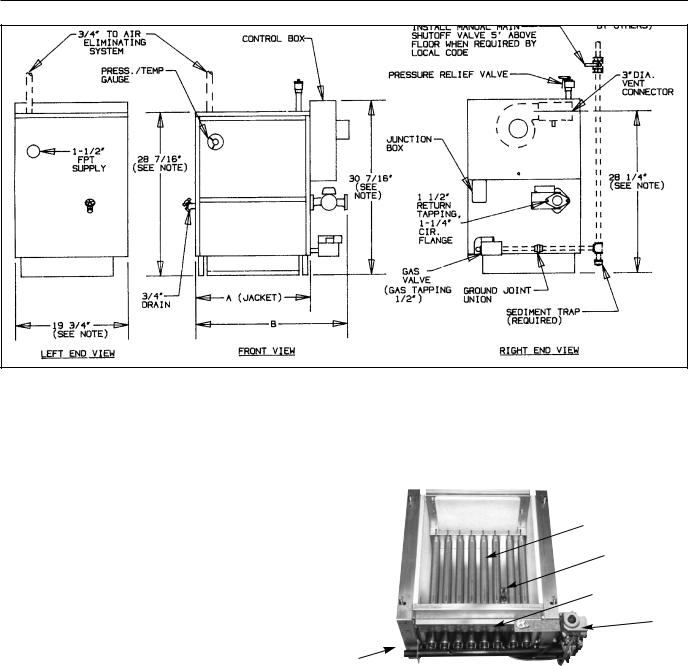
Figure 1. Views - Dimensions - Data
LEFT END VIEW |
|
FRONT VIEW |
|
RIGHT END VIEW |
NOTE: Height dimensions increase by 13⁄4" and depth increases to 221⁄4" when combustible floor kit is used.
|
|
|
|
|
|
|
|
|
|
|
Approx. |
|
Figure 2. Base Assembly Victory II - VHS Boiler |
|||||
Boiler |
Input |
|
|
No. of |
|
|
|
|
Total Wt. |
|
|
|
|
|
|
|||
|
|
|
|
|
|
Full of |
|
|
|
|
|
|
||||||
Model |
|
Btuh |
|
Sections |
A |
|
|
B |
Water (lb.) |
|
|
|
|
|
|
|||
VHS-30 |
30,000 |
|
2 |
81⁄8" |
|
145⁄8" |
190 |
|
|
|
|
|
|
Burners |
||||
VHS-60 |
60,000 |
|
3 |
111⁄8" |
|
175⁄8" |
250 |
|
|
|
|
|
|
|
||||
VHS-90 |
90,000 |
|
4 |
141⁄8" |
|
205⁄8" |
310 |
|
|
|
|
|
|
Pilot |
||||
VHS-120 |
120,000 |
|
5 |
171⁄8" |
|
235⁄8" |
365 |
|
|
|
|
|
|
Burner |
||||
VHS-150 |
150,000 |
|
6 |
201⁄8" |
|
265⁄8" |
425 |
|
|
|
|
|
|
|||||
|
|
|
|
|
|
|
|
access door |
||||||||||
VHS-180 |
180,000 |
|
7 |
231⁄8" |
|
295⁄8" |
485 |
|
|
|
|
|
|
Gas valve |
||||
|
|
|
|
|
|
|
|
|
|
|
|
|
|
|
|
|
|
|
|
|
|
|
|
|
|
|
|
|
|
Gas manifold |
|
|
|
|
|
||
|
|
|
|
|
|
|
|
|
|
|
|
|
|
|
||||
|
|
|
|
|
|
|
|
|
Orifice Sizes for High Altitudes |
|
|
|
|
|||||
|
|
Orifice |
|
|
|
Includes 4% Reduction for Each 1000 Feet |
|
|
|
|||||||||
Gas |
|
|
|
|
|
|
|
|
|
|
|
|
|
|
|
|
||
|
|
|
|
|
|
|
|
|
|
|
|
|
|
|
|
|||
|
|
|
|
|
|
|
Elevation — Feet |
|
|
|
|
|
||||||
|
Size for |
|
|
|
|
|
|
|
|
|
|
|
||||||
Type |
|
|
|
|
|
|
|
|
|
|
|
|
||||||
|
Sea Level |
2000 |
3000 |
4000 |
5000 |
6000 |
7000 |
8000 |
9000 |
10000 |
|
|
||||||
|
|
|
|
|||||||||||||||
Natural |
|
#49 |
|
|
50 |
50 |
50 |
51 |
51 |
51 |
52 |
52 |
52 |
|
|
|||
Propane |
|
#57 |
|
|
58 |
59 |
59 |
60 |
60 |
61 |
62 |
63 |
63 |
|
|
|||
|
|
|
|
|
|
|
|
|
|
|
|
|
|
|
|
|
|
|
Orifice sizes indicated for sea level above are factory installed in boiler unless otherwise specified by the local authority. Orifice table is based on a higher heating value between 1000 Btuh and 1010 Btuh for Natural Gas (See page 19, if local higher heating value exceeds these numbers). See page 19, for burner input adjustment.
2
VICTORY II VHS Models
INSTALLATION REQUIREMENTS
The installation must conform to the requirements of the authority having jurisdiction or, in the absence of such requirements, to the National Fuel Gas Code, ANSI Z223.1- latest edition.
This installation must also conform to the additional requirements in this Slant/Fin Instruction Book.
NATURAL GAS-FIRED BOILER LOCATION
Provide a level, solid foundation for the boiler. Location should be as near as possible to chimney or outside wall so that the flue pipe from boiler is short and direct. (See Appendix A for vent terminal location restrictions.) The location should also be such that the gas ignition system components are protected from water (dripping, spraying, rain, etc.) during appliance operation and service (circulator replacement, condensate trap, control replacement, etc.).
WARNING
LIQUEFIED PETROLEUM (L.P.) PROPANE GAS-FIRED BOILER LOCATION
REQUIRES SPECIAL ATTENTION Liquefied Petroleum (L.P.) propane gas is heavier than air. Therefore, propane boilers, piping, valves should NOT be
installed in locations where propane leaking from defective equipment and piping will "pool" in a basement or other space below the leak.
A spark or flame from the boiler or other source may ignite the accumulated propane gas causing an explosion or fire. Provide a level, solid foundation for the boiler. Location should be as near the chimney as possible so that the flue pipe from boiler to chimney is short and direct.
The UNIFORM MECHANICAL CODE may be in effect in your geographic area.
The following precautions are cited by the 1994 UNIFORM MECHANICAL CODE, section 304.6:
"LPG Appliances. Liquefied petroleum gas-burning appliances shall not be installed in a pit, basement or similar location where heavier-than-air-gas might collect. Appliances so fueled shall not be installed in an abovegrade under-floor space or basement unless such location is provided with an approved means for removal of unburned gas."
Consult Chapter 5 of the 1994 UNIFORM MECHANICAL CODE for design criteria of the "approved" means for removal of unburned gas.
BOILER FOUNDATION
A.Provide a solid, level foundation, capable of supporting the weight of the boiler filled with water, and extending at least 2" past the jacket on all sides. See dimensions of boilers, page 2.
B.For installation on non-combustible floors only*.
C.If boiler is to be located over buried conduit containing electric wires or telephone cables, consult local codes or the National Board of Fire Underwriters for specific requirements.
*Installation on combustible flooring allowed only with proper Combustible Floor Kit. Kit part number is printed on boiler rating plate. In no case may the boiler be installed on carpeting.
MINIMUM CLEARANCES FROM COMBUSTIBLE CONSTRUCTIONS
A.Minimum clearances to the exterior surfaces of the boiler shall be as follows:
MINIMUM ALCOVE AND CLOSET CLEARANCE
|
For Combustible |
Recommended |
||||
Surface |
|
Construction |
for Service |
|||
Front |
|
|
|
|
|
|
|
6" |
18" |
||||
Rear |
6" |
18" |
||||
Left Side |
6" |
18" |
||||
Right Side |
12" |
24" |
||||
Top |
12" |
12" |
||||
Flue Connector: |
|
|
|
|
|
|
Enclosed — |
6" |
6" |
|
|||
Unenclosed — |
2" |
6" |
|
|||
|
|
|
|
|
|
|
B.Provide accessibility clearance of 24" on sides requiring servicing and 18" on sides used for passage.
C.All minimum clearances shown above must be met. This may result in increased values of some minimum clearances in order to maintain the minimum clearances of others.
D.Clearance from hot water pipes shall be 1 inch**.
**At points where hot water pipes emerge from a floor, wall or ceiling, the clearance at the opening through the finished floor boards or wall or ceiling boards may be not less than 1/2 inch. Each such opening shall be covered with a plate of uncombustible material.
Figure 3.
SAFETY
KEEP THE BOILER AREA CLEAR AND FREE FROM COMBUSTIBLE MATERIALS, GASOLINE AND OTHER FLAMMABLE VAPORS AND LIQUIDS.
3

VICTORY II VHS Models
BOILER ROOM AIR SUPPLY AND VENTILATION
An ample supply of air is required for combustion and ventilation. When buildings are insulated, caulked and weatherstripped, now or later on, direct openings to outside may be required and should be provided. If the boiler is not near an outside wall, air may be ducted to it from outside wall openings.
Provisions for combustion and ventilation air must be made in accordance with section 5.3, Air for Combustion and Ventilation, of the National Fuel Gas Code, ANSI Z223.1-latest edition, or applicable provisions of the local building codes. The following recommendation applies to buildings of ener- gy-saving construction, fully caulked and weatherstripped.
INSTALLATION IN ENCLOSED BOILER ROOM REQUIRES TWO UNOBSTRUCTED OPENINGS FOR PASSAGE OF AIR INTO THE BOILER ROOM:
1.Air drawn horizontally from outdoors DIRECTLY through an outside wall; one louvered opening near the floor and one louvered opening near the ceiling, each opening with a minimum FREE air passage area of 1 square inch per 4000 Btuh of total appliances’ input.
2.Air drawn horizontally through HORIZONTAL DUCTS; one opening near the floor and one opening near the ceiling, each opening with a minimum FREE air passage area of 1 square inch per 2000 Btuh of total appliances’ input.
3.Air drawn VERTICALLY from outdoors; one opening at the floor and one opening at the ceiling, each opening with a minimum FREE air passage area of 1 square inch per 4000 Btuh of total appliances’ input.
4.Air drawn from inside the building; one opening near the floor and one opening near the ceiling, each opening with a minimum FREE air passage area of 1 square inch per 1000 Btuh of total appliances’ input.
IF BOILERS ARE INSTALLED ADJACENT TO OTHER FUEL BURNING EQUIPMENT, THE AREA OF FREE OPENINGS MUST BE APPROPRIATELY INCREASED TO ACCOMMODATE THE ADDITIONAL LOAD.
Openings must never be reduced or closed. If doors or windows are used for air supply, they must be locked open. Protect against closure of openings by snow and debris. Inspect frequently.
No mechanical draft exhaust or supply fans are to be used in or near the boiler area.
The flow of combustion and ventilating air to the boiler must not be obstructed.
FLUE GAS VENTING REQUIREMENTS
The Victory II series boiler is a high efficiency, mechanically induced draft boiler and, therefore, requires different venting arrangements than natural draft, lower efficiency boilers.
THE FOLLOWING INSTRUCTIONS MUST BE CAREFULLY READ AND FOLLOWED IN ORDER TO AVOID ANY HAZARDOUS CONDITIONS DUE TO IMPROPER INSTALLATION OF THE FLUE GAS VENTING SYSTEM.
The vent piping installation MUST be in accordance with these instructions and with ANSI Z223.1-latest edition NATIONAL FUEL GAS CODE, Part 7, Venting of Equipment. Other local codes may also apply and must be followed. Where there is a conflict between these requirements, the more stringent case shall apply.
The use of a vent damper is NOT permitted on this boiler series.
Approved Venting Applications
Victory II model VHS-90 through 180 are Category III and VHS-30 and 60 are Category II boilers, these boilers must be vented by proper 3" diameter venting system (see Category II and III venting - page 5).
Models VHS-90 through 180 are also Category I boilers when using a minimum of 5" diameter connector and vented into a natural draft chimney or Type “B” vent using a 3"x5" diameter vent adapter (see Category I venting - page 10).
4
VICTORY II VHS Models
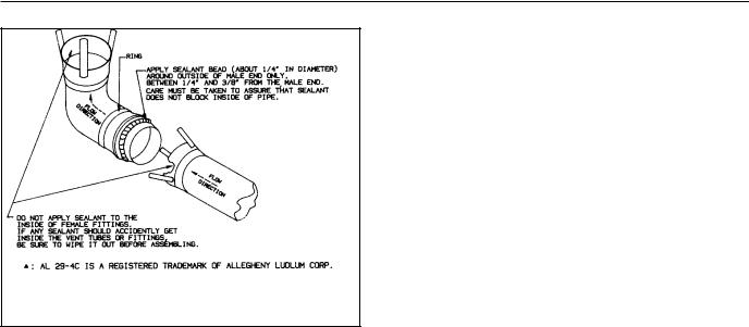
Figure 4. Vent Sealing Instructions
(Consult vent manufacturer’s instructions.)
CATEGORY II AND III VENTING
1.Vent Material
A)The vent system for horizontal or vertical venting
(Category II and III) must be UL listed single wall 3" diameter AL29-4C▲ stainless steel material. The following manufacturers’ systems are approved for use within a specified minimum and maximum equivalent vent length for each model. Proper adapter must be used as a connector between Victory II boilers flue collar and venting system as shown below:
Manufacturer |
Type/System |
Adapter Part |
Sealant |
|
|
No. |
|
Heat-Fab. Inc. |
Saf-T Vent |
Not Required |
RTV 106 or Dow |
|
|
|
Corning 732 |
|
|
|
|
Heat-Fab. Inc. |
Saf-T Vent |
Not Required |
Not Required |
|
EZ Seal |
|
|
ProTech System, |
FasNSeal |
FSA-SLB-3 |
Not Required |
Inc. |
|
|
|
Flex-L |
StaR-34 |
SRASFA3 |
GE-1S806 |
International, Inc. |
|
|
|
Z-Flex, Inc. |
Z-Vent |
O2SVSSLA2 |
GE, RTV 106 |
|
|
|
|
Heat-Fab Part Numbers for various items of vent system are listed in Slant/Fin Part List, Publication No. VHS-10PL.
B)When joining the various components of the above listed vent systems, the manufacturers’ instructions should be closely followed to insure proper sealing.
C)Use sealant specified by vent system manufacturer for sealing of pipe and fittings. See Figure 4 for proper application of vent pipe sealing for Safe-T vent system by Heat-Fab. Inc.
D)All vent connections must be liquid and pressure tight
E)Flue vent system CANNOT be cut to length. Consult manufacturer’s instructions. For Heat-Fab system, use slip joint connector to adjust pipe lengths dimensions.
F)DO NOT use plastic or galvanized flue pipe.
2. Flue Length Restriction
Maximum and minimum equivalent flue length for different systems are given in the tables on page 6. Equivalent flue length is sum of straight flue lengths and equivalent length of elbows. The vent termination is in addition to the allowed equivalent lengths.
Example: Boiler Model VHS-180 is to be installed at sea level with 2 elbows using Heat-Fab vent system. Maximum straight run would be: 40 - 2 x 3 = 34ft. If same boiler is to be installed in Colorado Springs (5,980 ft. altitude), the maximum straight run would be: 20 - 2 x 3 = 14 ft.
3.Installation
A.Horizontal Venting:
Figures 5 and 6 show typical horizontal venting. For combustible wall passage of vent piping a U.L. listed thimble must be used. See Figures 5 and 6 for wall thimble Part Numbers and more information.
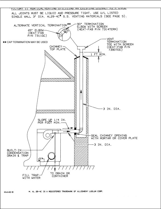
B.Vertical Venting:
Figure 7 shows typical vertical venting. A fire stop is required for each ceiling and floor penetration. An existing chimney (see Figure 8) may be used as a chase for vertical venting. Other appliances CANNOT be vented into the same chimney or vent pipe within the chimney.
For both, horizontal and vertical venting, the following points MUST be followed:
A.All Victory II boilers are equipped with a built-in condensation drain and trap. The trap loop must be filled with water. DO NOT operate the boiler without filling the trap with water to prevent flue gas discharge into space. The drain should extend to a floor drain or to a container which may require emptying periodically.
B.The horizontal vent pipe must be sloped upward from the boiler at a pitch of at least 1/4" per 1 foot of run, so that the condensate from the vent system runs to the drain trap.
C.The horizontal vent pipes must be supported with pipe straps at intervals no greater than indicated by vent pipe manufacturer’s instructions. The vertical portion vent pipe also must be supported per manufacturer’s instructions.
D.Minimum clearances of vent pipes from combustible constructions must be maintained (see Page 3).
E.Common venting with other appliances or another Victory II boiler is NOT allowed.
F.The vent piping must terminate with a screened elbow or tee. See Figures 5 and 6 for horizontal and 7 and 8 for vertical termination information. A cap termination may be used for vertical venting.
G.See Appendix A for vent system location and condensation drain requirements.
H.For roof passage of vent piping a U.L. listed roof flashing must be used.
5
▲: AL 29-4C is a registered trademark of Allegheny Ludlum Corp.

VICTORY II VHS Models
Heat-Fab Saf-T Vent System
|
Max. Equivalent Length (Ft.) |
|
|
||
|
|
|
|
Equivalent |
|
|
|
|
|
|
|
|
0 to |
5500 to |
7000 to |
Length of |
|
Boiler |
5500 Ft. |
7000 Ft. |
10,000 Ft. |
each 90° |
Minimum |
Model No. |
Altitudes |
Altitudes |
Altitudes |
Elbow, Ft. |
Length, Ft. |
|
|
|
|
|
|
VHS-30, |
40 |
40 |
40 |
3 |
2 |
60, 90 |
|
|
|
|
|
and 120 |
|
|
|
|
|
|
|
|
|
|
|
VHS-150 |
40 |
40 |
20 |
3 |
2 |
|
|
|
|
|
|
VHS-180 |
40 |
20 |
20 |
3 |
2 |
|
|
|
|
|
|
ProTech FasNSeal System
|
Max. Equivalent Length (Ft.) |
|
|
||
|
|
|
|
Equivalent |
|
|
|
|
|
|
|
|
0 to |
5500 to |
7000 to |
Length of |
|
Boiler |
5500 Ft. |
7000 Ft. |
10,000 Ft. |
each 90° |
Minimum |
Model No. |
Altitudes |
Altitudes |
Altitudes |
Elbow, Ft. |
Length, Ft. |
|
|
|
|
|
|
VHS-30, |
30 |
30 |
30 |
6 |
2 |
60, 90 |
|
|
|
|
|
and 120 |
|
|
|
|
|
|
|
|
|
|
|
VHS-150 |
30 |
30 |
15 |
6 |
2 |
|
|
|
|
|
|
VHS-180 |
30 |
15 |
15 |
6 |
2 |
|
|
|
|
|
|
Flex-L StaR-34 and Z-Flex Z-Vent System
|
Max. Equivalent Length (Ft.) |
|
|
||
|
|
|
|
Equivalent |
|
|
|
|
|
|
|
|
0 to |
5500 to |
7000 to |
Length of |
|
Boiler |
5500 Ft. |
7000 Ft. |
10,000 Ft. |
each 90° |
Minimum |
Model No. |
Altitudes |
Altitudes |
Altitudes |
Elbow, Ft. |
Length, Ft. |
|
|
|
|
|
|
VHS-30, |
35 |
35 |
35 |
6 |
2 |
60, 90 |
|
|
|
|
|
and 120 |
|
|
|
|
|
|
|
|
|
|
|
VHS-150 |
35 |
35 |
18 |
6 |
2 |
|
|
|
|
|
|
VHS-180 |
35 |
18 |
18 |
6 |
2 |
|
|
|
|
|
|
Note: Vent termination is in addition to the allowed equivalent length.
6
VICTORY II VHS Models
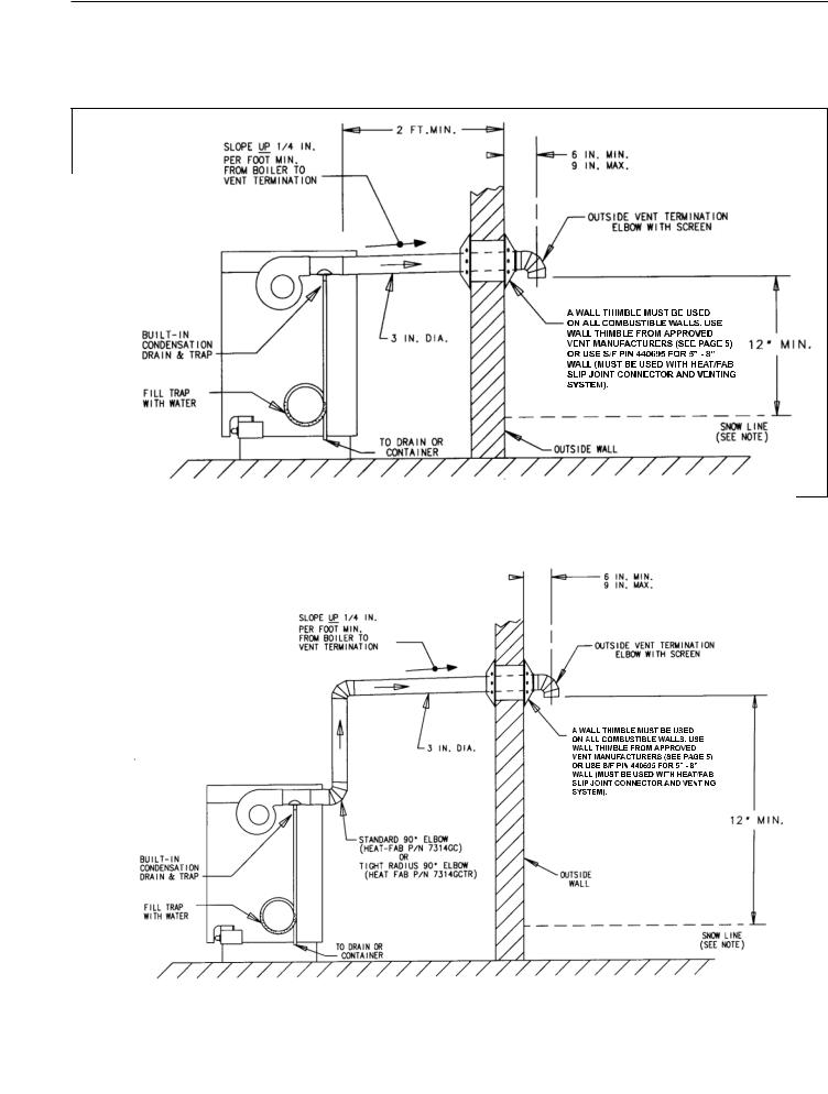
VICTORY II HORIZONTAL (SIDEWALL) VENTING
All joints must be liquid and pressure tight. Use U/L listed single wall 3" dia.
AL29-4C* S.S. venting materials
Figure 5 |
|
* Definition of Snow Line: Knowledge of local conditions will reveal the maximum height that repeated |
|
|
|
snowfalls accumulate to. The height should be used as the SNOW LINE. |
|
|
|
||
|
|
|
|
|
|
|
|
|
|
|
|
|
|
* Definition of Snow Line: Knowledge of local conditions will reveal the maximum height that repeated |
|
|
|
Figure 6 |
|
|
|||
|
|
snowfalls accumulate to. The height should be used as the SNOW LINE. |
44vh40-6 |
7 |
|
|
|
||||
|
|
|
|
||
|
*: AL 29-4C IS A REGISTERED TRADEMARK OF ALLEGHENY LADLUM CORP. |
REV.A |
|
|
|
|
|
|
|||
|
|
|
|
||

VICTORY II VHS Models
Figure 7.
8
VICTORY II VHS Models
Figure 8.
9
 Loading...