


EH-M3
MODEL EH-M3 ELECTRIC BOILER
Multi-stage electronic control with energy saving and other features.
EH-08-138-M3 through EH-20-138-M3, single phase, 3 wire, 120/208V
EH-08-134-M3 through EH-20-134-M3, single phase, 3 wire, 120/240V
EH-12-348-M3 through EH-20-348-M3, three phase, 4 wire, 120/208V
EH-12-344-M3 through EH-20-344-M3, three phase, 4 wire, 120/240V
OPERATION AND INSTALLATION INSTRUCTIONS
CONTENTS . . . . . . . . . . . . . . . . . . . . . . . . . . . . . . . . . . . .PAGE
Description . . . . . . . . . . . . . . . . . . . . . . . . . . . . . . . . . . . . . . . . .2
Mounting . . . . . . . . . . . . . . . . . . . . . . . . . . . . . . . . . . . . . . . . . . .2
Piping . . . . . . . . . . . . . . . . . . . . . . . . . . . . . . . . . . . . . . . . . . . . .2
Air Eliminator and Expansion Tanks . . . . . . . . . . . . . . . . . .2
Flow Switch . . . . . . . . . . . . . . . . . . . . . . . . . . . . . . . . . . . . .2
Bypass . . . . . . . . . . . . . . . . . . . . . . . . . . . . . . . . . . . . . . . . .2
Wiring (Warning: DO NOT turn on breakers on unit) . . . . . . . . .2
Wall Thermostat Flow Switch and Circulator . . . . . . . . . . .2
Service Connections and Electrical Ratings . . . . . . . . . . . .2
“Rough-In” Dimensions . . . . . . . . . . . . . . . . . . . . . . . . . . . . . . . .3
Start-up . . . . . . . . . . . . . . . . . . . . . . . . . . . . . . . . . . . . . . . . . . . .6
Fill System . . . . . . . . . . . . . . . . . . . . . . . . . . . . . . . . . . . . . .6
Air Elimination . . . . . . . . . . . . . . . . . . . . . . . . . . . . . . . . . . .6
Bypass Flow Adjustment . . . . . . . . . . . . . . . . . . . . . . . . . . .6
Check for Proper Boiler and System Operation . . . . . . . . .6
Operation . . . . . . . . . . . . . . . . . . . . . . . . . . . . . . . . . . . . . . . . . .6
Periodic Inspection . . . . . . . . . . . . . . . . . . . . . . . . . . . . . . . . . . .6
Electrical Connections . . . . . . . . . . . . . . . . . . . . . . . . . . . . . . . .7
Control Setup . . . . . . . . . . . . . . . . . . . . . . . . . . . . . . . . . . . . . . .8
Appendix A, B, C, & D . . . . . . . . . . . . . . . . . . . . . . . . . . . . . . . .9
IMPORTANT:
This manual must be left with owner and should be hung
on or adjacent to the boiler for reference.
Publication No. EH-M3-40 Rev. A • Printed in U.S.A. 1014
Part No. 793860000
MINITRON
LISTED
89C4
Heating Contractor
Address
Phone Number
Model Number
Serial Number
Installation Date

2 EH-M3-40 Boiler Operation and Installation Instructions
DESCRIPTION
The Minitron boiler is a low pressure hot water heating electric boiler.
The control is a two stage electronic control with energy saving and
other features. The heating elements are sheathed resistance type. The
heat exchanger is cast-iron. The heat exchanger is constructed, inspect-
ed, and stamped in accordance with Section IV of the American Society
of Mechanical Engineers (ASME) Boiler and Pressure Vessel Code. In
addition, the Minitron Boiler is equipped with a safety relief valve con-
forming to ASME requirements and two separate limit controls conform-
ing to U.L. requirements. The Minitron boiler is Underwriters'
Laboratories, Inc. listed.
MOUNTING THE BOILER ON A WALL
Be sure that the wall is vertically plumb and capable of carrying the
weight of the boiler and the system piping, when full of water. The boiler
full of water is approximately 100 lbs. Add to this the weight of the sys-
tem piping that the boiler will be supporting.
Be sure that there are studs available in the proper locations, for secur-
ing the boiler wall bracket and back panel.
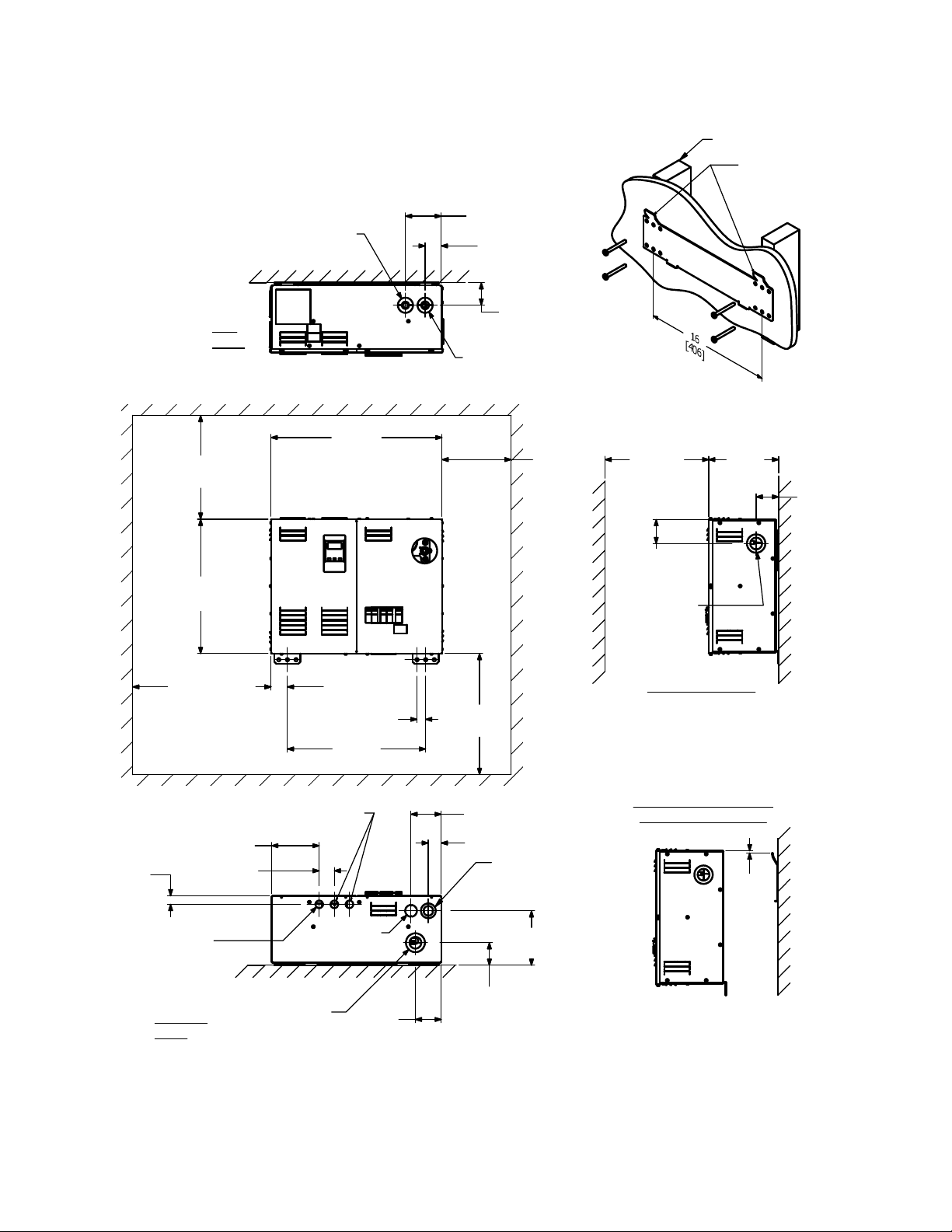
(See Figures 1 and 1a).
For wood stud walls, use lag screws or wood screws with a coarse
thread and a minimum of 3” in length.
For metal stud walls, use toggle-style bolts that are specifically designed
for such and maximum capacity exceeds the weight of the boiler and the
system piping when full of water.
DO NOT use anchors driven into sheetrock to hold the boiler up on the
wall. If mounting the boiler on a cement wall, use anchors that are
specifically designed for such, and maximum capacity exceeds the
weight of the boiler and the system piping, when full of water.
A. INSTALL THE WALL BRACKET. SEE FIGURE 1a.
1. Remove the wall bracket from the wood packing, by unfastening the
two screws that holds it in place, for shipping purposes only.
2. Select the location on the wall where the boiler will be mounted.
The upward facing tabs of the wall bracket will align with the top
surface of the boiler jacket.
3. For sheetrock and stud construction, locate the studs and
determine which set of holes in the wall bracket best align
with the center of the studs. For cement walls, determine a
location for the wall bracket to mount where the anchors will
be secure, devoid of seams or cracks.
4. Place the bracket in the selected location, with the 2 tabs
positioned up and facing outward, level it out, and mark the
holes to be used. A minimum of 4 of these holes must be
utilized, regardless of wall material.
5. Drill the appropriate diameter and depth holes for the
fasteners used in the wall, where marked.
6. Fasten the wall bracket to the wall, being sure that the tabs
face upward and outward, and the fasteners have engaged
the wall properly.
B. INSTALL THE BOILER ON THE WALL. SEE FIGURE 1.
1. Lift the boiler up against the wall, with the top edge of the jacket
slightly above the wall bracket tabs. Engage the boiler jacket near
top lip notches properly.
2. There are fastener holes in the lower area of the boiler rear
panel to ensure that the boiler does not move off the wall bracket.
Mark these 2 holes, with the boiler in place, then lift the boiler off
the wall bracket.
3. Determine which fastener type will best engage with the wall con-
struction at the location of the 2 market holes. Drill out the appro-
priate diameter and depth holes for the fasteners, where marked.
4. Lift the boiler up onto the wall bracket again, as described in
Step 1. Secure the boiler to the wall, with the 2 fasteners in the
lower rear panel area.
PIPING
Air Separator and Expansion Tanks
The recommended piping arrangement is shown in Figures 2 through 4.
Note that there is a built-in air eliminator in the heat exchanger (air vent,
however, is by others). A 1/8" air vent may be used (bushing is needed
for 1/2" NPT tapping). Additional air vents should be installed at points
just upstream from all drops in elevation of the piping system (high
points).
Relief Valve Discharge Piping
Use same size or larger piping than valve outlet piping. Must terminate
152mm ( 6”) minimum from floor with a plain (no threads) end. Place a
bucket under pressure relief valve discharge piping. Make sure dis-
charge is always visible. DO NOT hard-pipe to drain piping.
Flow Switch
A FLOW SWITCH MUST BE INSTALLED. It is intended to prevent the
burnout of heater elements should the circulator fail, or should air accu-
mulate in the boiler due to faulty air elimination (see Table 2 for flow
switch size required). FLOW SWITCH MUST BE INSTALLED IN HORI-
ZONTAL POSITION.
Bypass
The bypass shown must be set so that a sufficient amount of water can
circulate through the boiler when all zone valves are closed. See Figure 3.
Multi-zone Balancing
Raise all zone thermostat settings and verify that all zone valves are open
(not bypassed). Close all electrical panels. Turn on 10 amp control circuit
breaker ONLY. Pump should operate. Note the pressure reading on the
pump discharge. Lower each zone thermostat setting to close correspon-
ding zone valve. Adjust the corresponding balancing valve to maintain
pump discharge pressure. The pump discharge pressure should remain
the same when all zones are in bypass or when all zones are open or any
combination of opened and closed. See Figure 4.
WIRING
To wire the electric boiler, perform the following procedures:
1. Wall Thermostat Flow Switch and Circulator
• All circuit breakers ahead of and at boiler must be OFF. Remove
the Control Panel (left-hand front) Cover by removing 5 screws
from top, bottom and side flanges.
• The right-hand compartment under the Control Panel Cover con-
tains a terminal board marked, (SLANT/FIN “INTERFACE
BOARD”). Wire a 2-wire 24V room heating thermostat or the auxil-
iary end switch terminals of zone valves (see Figure 5) to terminals
3 and 4 at this time. The 1 and 2 terminals are for the flow switch.
The flow switch circuit is a low voltage circuit.
• Wire the circulator and connect 115V wires and conduit through
1/2" knockout. provided on bottom left hand corner, to the “INTER-
FACE BOARD” at terminals “L” and “N”, where it is marked “CIRC.
PUMP”.
2. Service Connections and Electrical Ratings
A. All circuit breakers ahead of and at boiler must be OFF.
Remove the Service Connection Panel (right hand front). Cover by
removing 5 screws from the top, bottom and side flanges (see
wiring diagram on back of the Service Connection Panel and
Figure 5).
B. Draw power feeder cable (75°C minimum) and conduit through
service knockout provided on top and bottom.
C.Connect hot lines to distribution block provided in service compart-
ment. A ground lead should be drawn and wired to the ground lug
in the service compartment. If rating plate indicates boiler is a sin-
gle phase 3-wire or 3-phase 4-wire model, draw a neutral wire #12
AWG maximum, 75˚C. minimum and connect to neutral lug mount
provided in service compartment. See Tables 1 and 3 for lug sizes
and current ratings.
3. Wiring Control
• See EM-10 Electronic Control Set Up Instructions #790860000
for setting up control.
EH-M3-40 Boiler Operation and Installation Instructions 3
12 [305]
MINIMUM
16 [406]
MINIMUM
(REQUIRED FOR
REPLACING
ELEMENTS)
14
[356]
8 [203]
MIN-
IMUM
STUDS
FACE TABS UP AND
FORWARD. INSTALL
TABS LEVEL.
16 [406]
BOILER MUST BE LEVEL
15 17/32
[395]
19 25/32
[503]
ø
1 3/4 [44]
(1/2" PLUG)
2 19/32
[66]
1 7/8 [48]
4 5/32 [105]
12 [305]
MINIMUM
8 3/32
[205]
2 19/32
[66]
ø
2 1/8 [54]
(1 1/4" SUPPLY)
6 9/32
[160]
3 [76]
1 1/2 [38]
3 1/2 [89]
5 1/2 [139]
7/8 [22] KNOCKOUT
(110V CONDUIT FOR
CIRCULATOR OR
TRANSFORMER)
1
[25]
7/8 [22] KNOCKOUTS
(24V CONNECTIONS)
ø
1 3/4 [44]
(3/4" RELIEF VALVE)
ø
2 3/16 [56]
(1 1/4" RETURN)
1 [25] TYP
1 29/32 [48]
2 25/32
[70]
RIGHT SIDE VIEW
TOP
VIEW
BOTTOM
VIEW
SECURE WALL
BRACKET INTO STUDS
WITH APPROPRIATE FASTENERS
1 3/4 [44]
TYP
2 19/32
[66]
WALL
WALL
WALL
WALL
MINITRON "ROUGH-IN" DIMENSIONS
BOILER HEIGHT ABOVE
WALL BRACKET TABS
1. UNIT MAY BE FULLY ENCLOSED
IF CLEARANCE DIMENSIONS ARE
RESPECTED.
2. DUAL DIMENSIONS ARE: INCH [MM]
1/4
[6]
ø
1 11/32 [35]
KNOCKOUT
DUAL KNOCKOUTS
ø
1 3/4 [44]
ø
1 1/8 [29]
Figure 1.
Figure 1a.
4 EH-M3-40 Boiler Operation and Installation Instructions
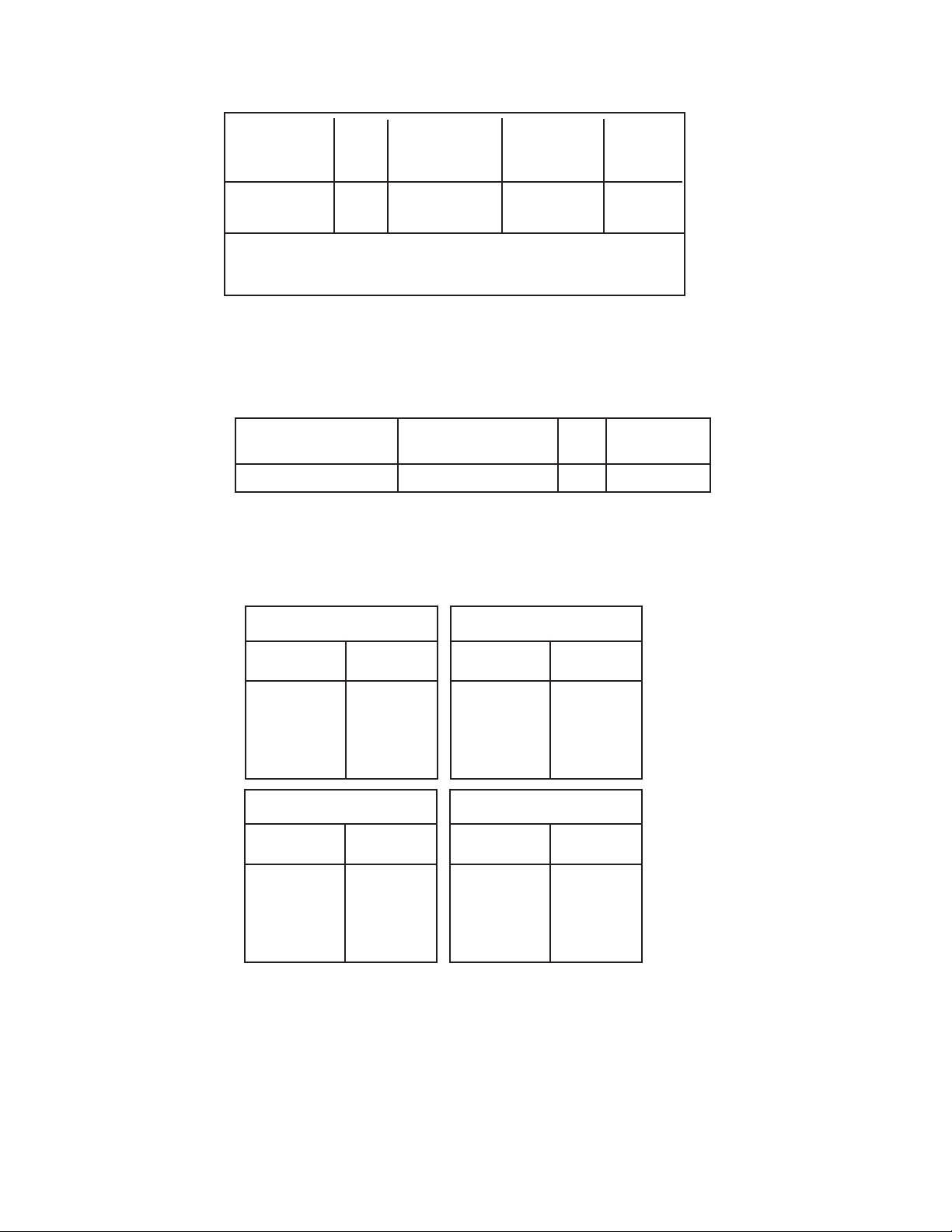
Table 1. Lug Sizes
Table 2. Flow Switch Size Selection
* Straight pipe upstream and downstream of flow switch.
Model No.
Flow Switch
McDonnell & Miller No.
Pipe
Size
Minimum
Pipe Length*
EH-8-M3 thru EH-20-M3 FS4-3T3-1 1" 6-1/2”
Distribution Block
Grounding Lug
Neutral Lug
Wire Size Wire Size Wire Size
Model Phase CU-AL† CU-AL† CU-AL†
EH-8 thru 20 1 6-2/0 6-2/0 6-2/0
EH-12 thru 20 3 6-2/0 6-2/0 6-2/0
Neutral Lug Wire Size:For 3-wire single phase and 4-wire 3 phase
models equipped with circuit breakers. The neutral tap is for the
circulator and control transformer.
† ALUMINUM conductors may be used, lug size, conduit size, ampacity and all
applicable codes permitting.
Table 3. Current Ratings
† Leg with the highest value of line current of an unbalanced 3-phase load.
‡ 125 VAC maximum rating of all hot conductors.
SINGLE PHASE 3 WIRE, 120/208V
‡
Basic Model
No.
Heater Amperes
@ 208V
EH8-13-8-M3
EH10-13-8-M3
EH12-13-8-M3
EH16-13-8-M3
EH20-13-8-M3
29
36
43.4
58
72
SINGLE PHASE 3 WIRE, 120/240V
‡
Basic Model
No.
Heater Amperes
@ 240V
EH8-13-4-M3
EH10-13-4-M3
EH12-13-4-M3
EH16-13-4-M3
EH20-13-4-M3
33
42
50
67
83
THREE PHASE 4 WIRE, 120/208V
WYE CIRCUIT ONLY
‡
Basic Model
No.
Heater Amperes †
@ 208V
–
–
EH12-34-8-M3
EH16-34-8-M3
EH20-34-8-M3
–
–
43
58
†
72
†
THREE PHASE 4 WIRE, 120/240V
DELTA CIRCUIT ONLY
‡
Basic Model
No.
Heater Amperes †
@ 240V
–
–
EH12-34-4-M3
EH16-34-4-M3
EH20-34-4-M3
–
–
50
67
†
83
†
 Loading...