


GAS-FIRED CAST-IRON BOILERS FOR NATURAL AND L.P. PROPANE GASES
“S” AND “SX” MODELS
SENTRY® HOT WATER MODELS S-34 THROUGH S-150 and SX-150 THROUGH SX-210
INSTALLATION AND OPERATING INSTRUCTIONS
CONTENTS. . . . . . . . . . . . . . . . . . . . . . . . . . . . . . . . PAGE
Dimensions . . . . . . . . . . . . . . . . . . . . . . . . . . . . . . . . . . 2,3
Installation Requirements:
Boiler Location . . . . . . . . . . . . . . . . . . . . . . . . . . . . . . . 3
Boiler Foundation . . . . . . . . . . . . . . . . . . . . . . . . . . . . . 3
Chimney Requirements . . . . . . . . . . . . . . . . . . . . . . . . 4
Minimum Clearance . . . . . . . . . . . . . . . . . . . . . . . . . . . 4
Draft Hood . . . . . . . . . . . . . . . . . . . . . . . . . . . . . . . . . . 4
Vent Piping . . . . . . . . . . . . . . . . . . . . . . . . . . . . . . . . . . 4
Vent Damper Installation . . . . . . . . . . . . . . . . . . . . 5,6,7
Gas Piping . . . . . . . . . . . . . . . . . . . . . . . . . . . . . . . . . . 7
Electrical Controls and Wiring . . . . . . . . . . . . . . . . . . . 8
Boiler Room Air Supply and Ventilation . . . . . . . . . . . . 8
Water Piping at Boiler . . . . . . . . . . . . . . . . . . . . . . . . . 8
Operating Instructions:
Filling and Venting Water Systems. . . . . . . . . . . . . . . . 8 Initial Start, Safety and Lighting Instructions . . . . . 9,10 Burner Adjustment, Checking Gas Input . . . . . . . 10,11
Care and Maintenance
General Maintenance. . . . . . . . . . . . . . . . . . . . . . . . . 11 Water Level Check . . . . . . . . . . . . . . . . . . . . . . . . . . . 12 Annual Inspection and Cleaning . . . . . . . . . . . . . . . . 12 Safety Check for Control Systems . . . . . . . . . . . . . . . 12 Protection from Freezing/Water Treatment. . . . . . . . . 12 Keeping Area Clear . . . . . . . . . . . . . . . . . . . . . . . . . . 12
Sequence of Operations . . . . . . . . . . . . . . . . . . . . . . . . . 13 Wiring Diagrams . . . . . . . . . . . . . . . . . . . . . . . . . . . . 14,15 Pump or Valve Zoning of Water Boilers . . . . . . . . . . . . . 16 Troubleshooting Guide . . . . . . . . . . . . . . . . . . . . . . . . . . 17 Piping a Heating-Cooling System . . . . . . . . . . . . . . . . . . 18 Replacement Parts . . . . . . . . . . . . . . . . . . . . . . . . . . . . . 18 Appendix A . . . . . . . . . . . . . . . . . . . . . . . . . . . . . . . . . . . 19
IMPORTANT
READ ALL OF THE FOLLOWING WARNINGS AND STATEMENTS BEFORE READING THE INSTALLATION INSTRUCTIONS
WARNING
LIQUEFIED PETROLEUM (L.P.)
PROPANE GAS-FIRED BOILERS
Installation location ONLY as permitted in paragraph entitled "LIQUEFIED PETROLEUM (L.P.) PROPANE GASFIRED BOILER LOCATION" on page 4 of this instruction book.
The above warning does not apply to NATURAL gasfired boilers.
The installation must conform to the requirements of the authority having jurisdiction or, in the absence of such requirements, to the National Fuel Gas Code, ANSI Z223.1-latest edition. The installation must also conform to the additional requirements in this Slant/Fin Instruction Book.
In addition, where required by the authority having jurisdiction, the installation must conform to American Society of Mechanical Engineers Safety Code for Controls and Safety Devices for Automatically Fired Boilers, No. CSD-1. If there is any conflict in the above requirements, then the more stringent requirement will apply.
This manual must be left with owner and should be hung on or adjacent to the boiler for reference.
WARNING
This boiler, gas piping and accessories must be installed, connected, serviced and repaired by a trained, experienced service technician, familiar with all precautions required for gas-fired equipment and licensed otherwise qualified, in compliance with the authority having jurisdiction.
Heating Contractor |
|
|
|
Boiler Model Number |
|
|
|
|
|
|
|
|
|
|
|
Address |
|
|
|
Boiler Serial Number |
|
|
|
|
|
|
|
|
|
|
|
Phone Number |
|
|
|
Installation Date |
|
|
|
|
|
|
|
|
|
|
|
|
|
|
|
|
|
|
|
Printed in U.S.A. 605 |
PUBLICATION S-40 |
Part No. 46-0528 |
Rev. N |

2 |
Sentry |
|
|
|
|
Sentry |
|
|
|
|
|
|
|
|
|
|
|
|
|
|
|
|
|
|
|
|
|
|
|
|
|
|
|
|
|
|
|
|
|
|
|
|
|
3 |
||||||||
|
|
|
|
|
|
|
|
|
|
|
|
|
|
|
|
|
|
|
|
|
|
|
|
|
|
|
|
|
|
|
|
|
|
|
|
|
|
|
|
|
|
|
|
|
|
|
|
|
|
|
|
|
|
|
|
|
|
|
|
|
|
|
|
|
|
|
|
|
|
|
|
|
|
|
|
|
|
|
|
|
|
|
|
|
Approx. |
|
|
|
|
|
|
||
|
|
|
|
|
|
|
|
|
|
|
|
|
|
|
|
|
|
|
Dimensions |
|
|
|
|
|
|
|
|
|
|
|
|
|
|
|
|
|
||||||||||
|
|
|
|
|
|
|
|
|
|
|
|
|
|
|
|
|
|
|
|
|
(inches) |
|
|
|
|
|
|
|
|
|
|
|
|
Total Wt. |
|
|
|
|
|
|
||||||
|
|
|
|
|
|
|
|
|
|
|
|
|
|
|
|
|
|
|
|
|
|
|
|
|
|
|
|
|
|
|
|
|
|
|
|
|
|
|
Full of |
|
|
|
|
|
|
|
|
|
|
|
|
|
|
|
|
|
|
|
|
|
|
|
|
|
|
|
|
|
|
|
|
|
|
|
|
|
|
|
|
|
|
|
|
|
|
|
|
|
|
|
|||
|
Boiler |
|
|
No. of |
|
|
|
|
|
|
|
|
|
|
|
|
|
|
|
|
|
|
|
|
|
|
|
|
|
|
|
|
|
|
|
|
|
|
|
|
|
|
|
|
||
|
|
|
|
|
|
|
|
|
|
|
|
|
|
|
|
|
|
|
|
|
|
|
|
|
|
|
|
|
|
|
|
|
|
G |
|
Water (lb.) |
|
|
|
|
|
|
||||
|
Model |
|
|
Sect. |
|
|
|
|
A |
|
|
|
|
B |
|
|
|
C |
|
|
|
|
D |
|
|
|
|
E |
|
|
|
F |
|
|
|
|
|
CHIMNEY RECOMMENDATIONS |
||||||||
|
|
|
|
|
|
|
|
|
|
|
|
|
|
|
|
|
|
|
|
|
|
|
|
|
|
|
|
|
|
|
|
|
|
(max) |
|
|
|
|
||||||||
|
|
|
|
|
|
|
|
|
|
|
|
|
|
|
|
|
|
|
|
|
|
|
|
|
|
|
|
|
|
|
|
|
|
|
|
|
|
|
|
|||||||
|
|
|
|
|
|
|
|
|
|
|
|
|
|
|
|
|
|
|
|
|
|
|
|
|
|
|
|
|
|
|
|
|
|
|
|
|
|
|
|
|||||||
|
|
|
|
|
|
|
|
|
|
|
|
|
|
|
|
|
|
|
|
|
|
|
|
|
|
|
|
|
|
|
|
|
|
|
|
|
|
|
|
|
|
HEIGHT:15 ft. (minimum) from draft |
||||
|
S-34 |
|
2 |
|
|
|
81⁄8" |
|
|
145⁄8" |
|
|
4 |
|
|
|
33" |
|
|
|
|
— |
|
|
— |
|
|
61⁄4" |
190 |
|
|
|||||||||||||||
|
|
|
|
|
|
|
|
|
|
|
|
|
|
|
|
|
|
|
|
hood skirt to top of chimney. |
||||||||||||||||||||||||||
|
S-60 |
|
3 |
|
|
111⁄8" |
|
|
175⁄8" |
|
|
4 |
|
|
|
37" |
|
|
|
|
41⁄2" |
|
26" |
|
|
|
61⁄4" |
250 |
|
|
||||||||||||||||
|
|
|
|
|
|
|
|
|
|
|
|
|
|
|
|
|
|
|
INSIDE DIAMETER: Same as dimen- |
|||||||||||||||||||||||||||
|
S-90 |
|
4 |
|
|
141⁄8" |
|
205⁄8" |
|
5 |
|
|
|
37" |
|
|
|
|
51⁄2" |
|
|
251⁄2" |
|
|
61⁄4" |
310 |
|
|
sion C (or larger). |
|||||||||||||||||
|
S-120 |
|
5 |
|
|
171⁄8" |
|
|
235⁄8" |
|
|
6 |
|
|
|
37" |
|
|
|
|
71⁄2" |
|
25" |
|
|
|
61⁄4" |
365 |
|
|
NOTE: Larger chimney may be |
|||||||||||||||
|
|
|
|
|
|
|
|
|
|
|
|
|
|
|
|
|
|
|
required if two or more boilers or a boil- |
|||||||||||||||||||||||||||
|
|
|
|
|
|
|
|
|
|
|
|
|
|
|
|
|
|
|
|
|
|
|
|
|
|
|
|
|
|
|
|
|
|
|
|
|
|
|
|
|
|
|||||
|
S-150 |
|
6 |
|
|
201⁄8" |
|
265⁄8" |
|
7 |
|
|
|
37" |
|
|
|
|
81⁄2" |
|
|
241⁄2" |
|
|
81⁄4" |
425 |
|
|
er and another appliance are vented to |
|||||||||||||||||
|
|
|
|
|
|
|
|
|
|
|
|
|
|
|
|
|
|
|
|
|
|
|
|
|
|
|
|
|
|
|
|
|
|
|
|
|
|
|
|
|
|
a single chimney. |
||||
|
SX-150 |
|
6 |
|
|
201⁄8" |
|
|
265⁄8" |
|
|
6 |
|
|
|
511⁄2" |
|
|
101⁄2" |
|
|
107⁄8" |
|
|
61⁄4" |
425 |
|
|
||||||||||||||||||
|
|
|
|
|
|
|
|
|
|
|
|
|
|
|
|
Slant/Fin supplies vent dampers by |
||||||||||||||||||||||||||||||
|
SX-180 |
|
7 |
|
|
231⁄8" |
|
295⁄8" |
|
7 |
|
|
|
523⁄4" |
|
12" |
|
|
|
107⁄8" |
|
|
81⁄4" |
485 |
|
|
several manufacturers. Some are |
|||||||||||||||||||
|
SX-210 |
|
8 |
|
|
261⁄8" |
|
|
325⁄8" |
|
|
7 |
|
|
|
523⁄4" |
|
|
131⁄2" |
|
|
107⁄8" |
|
|
81⁄4" |
545 |
|
|
smaller than the indicated “G maxi- |
|||||||||||||||||
|
|
|
|
|
|
|
|
|
|
|
|
|
|
|
|
mum”. |
|
|
|
|||||||||||||||||||||||||||
|
|
|
|
|
|
|
|
|
|
|
|
|
|
|
|
|
|
|
|
|
|
|
|
|
|
|
|
|
|
|
|
|
|
|
|
|
|
|
|
|
|
|
|
|||
|
|
|
|
|
|
|
|
|
|
|
|
|
|
|
|
|
|
|
|
|
|
|
|
|
|
|
|
|
|
|
|
|
|
|
|
|
|
|
|
|
|
|
|
|||
|
|
|
|
|
|
|
|
|
|
|
|
|
|
Orifice |
|
|
|
|
|
|
|
|
|
|
Orifice Sizes |
for High Altitudes |
|
|
|
|
||||||||||||||||
|
|
|
|
|
|
|
|
|
|
|
|
|
|
|
|
|
|
|
|
|
|
|
Includes 4% Reduction for Each 1000 Feet |
|
|
|
|
|||||||||||||||||||
|
|
|
|
|
|
|
|
|
|
|
|
|
|
Size for |
|
|
|
|
|
|
|
|
|
|
|
|
|
|||||||||||||||||||
|
|
|
|
|
|
|
|
|
|
|
|
|
|
|
|
|
|
|
|
|
|
|
|
|
|
|
|
|
|
|
|
|
|
|
|
|
|
|
|
|
|
|
||||
|
|
|
|
|
|
|
|
|
|
|
|
|
|
|
|
|
|
|
|
|
|
|
|
|
|
|
|
|
|
|
|
|
|
|
|
|
|
|
|
|
|
|
||||
|
Boiler |
|
|
Gas |
|
|
|
|
|
|
|
|
|
|
|
|
|
|
|
Elevation - Feet |
|
|
|
|
|
|
||||||||||||||||||||
|
|
|
|
Sea |
|
|
|
|
|
|
|
|
|
|
|
|
|
|
|
|
|
|
|
|
||||||||||||||||||||||
|
Model |
|
|
Type |
|
Level |
2000 |
|
3000 |
|
|
4000 |
|
5000 |
|
|
6000 |
|
7000 |
|
8000 |
9000 |
10000 |
|
|
|||||||||||||||||||||
|
|
|
|
|
|
|
|
|
|
|
|
|
|
|
|
|
|
|
|
|
|
|
|
|
|
|
|
|
|
|
|
|
|
|
|
|
|
|
|
|
|
|
|
|
|
|
|
|
S-34 |
|
|
Natural |
|
47 |
|
|
48 |
|
|
48 |
|
|
|
49 |
|
|
49 |
|
|
|
49 |
|
|
50 |
|
50 |
51 |
51 |
|
|
|||||||||||||
|
|
|
|
Propane |
56 |
|
|
56 |
|
|
56 |
|
|
|
57 |
|
|
57 |
|
|
|
57 |
|
|
58 |
|
59 |
59 |
60 |
|
|
|||||||||||||||
|
|
|
|
|
|
|
|
|
|
|
|
|
|
|
|
|
|
|
|
|
|
|
|
|
|
|||||||||||||||||||||
|
|
|
|
|
|
|
|
|
|
|
|
|
|
|
|
|
|
|
|
|
|
|
|
|
|
|
|
|
|
|
|
|||||||||||||||
S-60 thru S-150 and |
|
|
Natural |
|
50 |
|
|
51 |
|
|
51 |
|
|
|
51 |
|
|
51 |
|
|
|
52 |
|
|
52 |
|
52 |
53 |
53 |
|
|
|||||||||||||||
SX-150 thru SX-210 |
|
|
Propane |
57 |
|
|
|
58 |
|
|
59 |
|
|
|
59 |
|
|
60 |
|
|
|
60 |
|
|
61 |
|
62 |
63 |
63 |
|
|
|||||||||||||||
|
|
|
|
|
|
|
|
|
|
|
|
|
|
|
|
|
|
|
|
|
|
|
|
|
|
|
|
|
|
|
|
|
|
|
|
|
|
|
|
|
|
|
|
|
|
|
Orifice indicated for sea level above are factory installed in boiler unless otherwise specified by the local authority. See III page 10 for burner input adjustment.
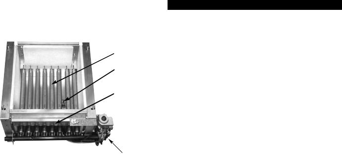
Base Assembly
Sentry Boiler
Burners
Pilot
Burner
Access
Door
Gas Valve
INSTALLATION REQUIREMENTS
The installation must conform to the requirements of the authority having jurisdiction or, in the absence of such requirements, to the National Fuel Gas Code, ANSI Z223.1-latest edition.
This installation must also conform to the additional requirements in this Slant/Fin Instruction Book.
NATURAL GAS-FIRED BOILER LOCATION
Provide a level, solid foundation for the boiler. Location should be as near as possible to chimney or outside wall so that the flue pipe from boiler is short and direct.
The location should also be such that the gas ignition system components are protected from water (dripping, spraying, rain, etc.) during appliance operation and service (circulator replacement, condensate trap, control replacement, etc.).
BOILER FOUNDATION
A.Provide a solid, level foundation, capable of supporting the weight of the boiler filled with water, and extending at least 2" past the jacket on all sides. See dimensions of boiler, page 2.
B.For installation on non-combustible floors only. The Combustible Floor Kit part number printed on the boiler rating plate is the only one to be used when installing on combustible floors. The boiler must not be installed on carpeting.
C.If boiler is to be located over buried conduit containing electric wires or telephone cables, consult local codes or the National Board of Fire Underwriters for specific requirements.

4 |
Sentry |
WARNING
LIQUEFIED PETROLEUM (L.P.) PROPANE
GAS-FIRED BOILER LOCATION
REQUIRES SPECIAL ATTENTION
Liquefied Petroleum (L.P.) propane gas is heavier than air. Therefore, propane boilers, piping, valves should not be installed in locations where propane leaking from defective equipment and piping will “pool” in a basement or other space below the leak.
A spark or flame from the boiler or other source may ignite the accumulated propane gas causing an explosion or fire. Provide a level, solid foundation for the boiler. Location should be as near the chimney as possible so that the flue pipe from boiler to chimney is short and direct.
The UNIFORM MECHANICAL CODE may be in effect in your geographic area
The following precautions are cited by the 1994 UNIFORM MECHANICAL CODE, section 304.6:
“LPG Appliances. Liquefied petroleum gas-burning appliances shall not be installed in a pit, basement or similar location where heavier-than-air-gas might collect. Appliances so fueled shall not be installed in an abovegrade under-floor space or basement unless such location is provided with an approved means for removal of unburned gas.”
Consult Chapter 5 of the 1994 UNIFORM MECHANICAL CODE for design criteria of the “approved” means for removal of unburned gas.
CHIMNEY REQUIREMENTS
A.Sentry boilers may be vented into a masonry vitreous tilelined chimney or type “B” venting system NOT EXPOSED to the OUTDOORS below the roof line.
Venting and sizing of venting system must be in accordance with Part 7, Part 10 and Appendix G of the National Fuel Gas Code ANSI Z223.1, NFPA 54, -latest edition which will be referred to as the National Fuel Gas Code. Local codes apply.
If a masonry chimney is exposed to the outdoors on one or more sides below the roof line (exterior chimney), ONE of the following options apply:
1.Chimney must be re-lined with a metallic liner. When this is done, the chimney will be considered NOT exposed to the outdoors and the requirements of the National Fuel Gas Code for NON-exposed chimneys and/or local codes will apply.
2.If an exposed tile-lined chimney is to be used WITHOUT
a metallic liner, the boiler must first meet the requirements of the following tables and paragraphs of the National Fuel Gas Code:
I.For Single Sentry Boiler - Paragraph 10.1.9 and table 10.11.
II.For multiple appliances - Paragraph 10.2.18 and table 10.12 (or 10.13 if applicable).
In addition, all requirements of Part 7, Part 10 and Appendix G of the National Fuel Gas Code and/or local codes apply.
B.If an existing boiler is removed from a common venting system, the common venting system may be too large
for proper venting of the remaining appliances connected to the common vent. Follow the test procedure shown in Appendix “A” on page 19 of this manual to insure proper operation of venting system and appliances.
C.Inspect for proper and tight construction. Any restrictions or obstructions must be removed. An existing chimney may require cleaning.
D.Chimney or vent must extend at least 3 feet above any ridge within 10 feet of the chimney.
MINIMUM CLEARANCES FROM COMBUSTIBLE CONSTRUCTIONS
SENTRY SERIES
MINIMUM CLEARANCE FOR COMBUSTIBLE CONSTRUCTION. MINIMUM ALCOVE AND CLOSET CLEARANCE.
|
S-34 through |
SX-150 through |
|
S-150 |
SX-210 |
Front |
6" |
6" |
Rear |
6" |
6" |
Left Side |
6" |
6" |
Right Side |
12" |
12" |
Top (above boiler) |
12" |
28" |
Flue Connector |
6" |
6" |
A.Minimum boiler clearances shall be as follows:
B.Provide accessibility clearance of 24” on sides requiring servicing and 18” on sides used for passage.
C.All minimum clearances shown above must be met. This may result in increased values of some minimum clearances in order to maintain the minimum clearances of others.
D.Clearance from hot water pipes shall be 1 inch**.
**At points where hot water pipes emerge from a floor wall or ceiling, the clearance at the opening through the finished floor, wall or ceiling boards may not be less than 1/2 inch. Each such opening shall be covered with a plate of non-combustible material.
SAFETY—
KEEP THE BOILER AREA CLEAR AND FREE FROM COMBUSTIBLE MATERIALS, GASOLINE AND OTHER FLAMMABLE VAPORS AND LIQUIDS.
DRAFT HOOD—
The draft hood supplied with SX-150 through SX-210 models is part of the listed boiler assembly. DO NOT alter the hood. See dimensions, page 2.
Attach the hood to the boiler flue outlet. Connect flue pipe full size of hood outlet. Vent damper must be installed on the outlet side of the hood. See Vent Piping, below.
VENT PIPING—
A.Vent piping installation must be in accordance with ANSI Z223.1-latest edition, National Fuel Gas Code, Part 7, Venting of Equipment. Other local codes may also apply and must be followed.
B.Boiler vent pipe must be the full diameter of the boiler outlet. See dimensions, page 2.
C.If more than one appliance vents into a common breeching, the area of the breeching must be equal to the area of the largest vent plus 50% of the area of the additional vent areas. Vent connectors serving appliances vented by natural draft shall not be connected into any portion of mechanical draft systems operating under positive pressure. Horizontal breeching or vent pipe should be as high as possible, consistent with codes, so that vertical vents from appliances will have a high rise above draft diverter openings. All horizontal runs must slope upwards not less than 1/4 inch per foot of run. Horizontal portions of the venting system
Sentry |
5 |
must be supported to prevent sagging by securing each joint with metal screws and by providing hanger spaced no greater than 5 feet apart.
D.Vent or breeching into chimney should not be inserted past the inside wall of the chimney liner.
E.All venting means should be inspected frequently. See Care and Maintenance and separate User's Information Manual.
VENT DAMPER INSTALLATION
The vent damper referred to in the following instructions is the Slant/Fin Corporation vent damper.
This device is design certified by A.G.A. for use ONLY on specific Slant/Fin Corp. gas boiler models. These boilers must also be equipped with a plate which states that the boiler may be used with a Slant/Fin Corp. automatic vent damper device and indicates the proper vent damper model number. This device cannot be used with millivolt ignition system.
A.INSTALLATION INSTRUCTIONS BEFORE YOU START TO INSTALL
1.Read this installation manual, the "DANGER" plate attached to the top of the boiler, the "WARNING" on the wiring diagrams, vent damper carton and operator cover.
2.Perform pre-installation inspection as required by ANSI specification Z21.66. (See Vent Damper Instructions.)
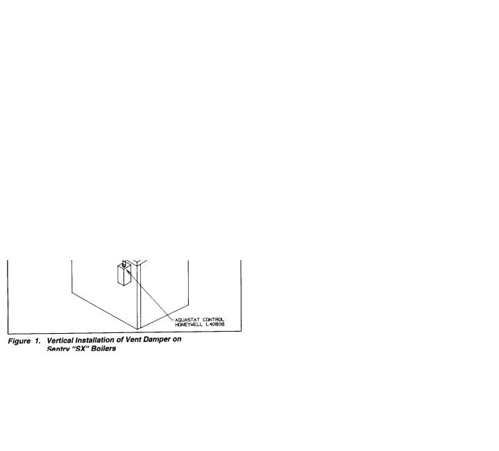
3.Select a proper, convenient location for vent damper. Vent damper may be installed vertical or horizontal on all models (see figures 1, 2 and 3).
Figure 1. Vertical Installation of Vent Damper on Sentry “SX” Boilers
4.Carefully unpack the unit. DO NOT FORCE IT OPEN OR CLOSED. Forcing the damper may damage the gear train and void the warranty.
Figure 2. Vertical Installation of Vent Damper on Sentry “S” Boilers
Figure 3. Horizontal or Sloping Installation of Vent Damper
6 |
Sentry |
Figure 4.
Figure 8. Damper Vane
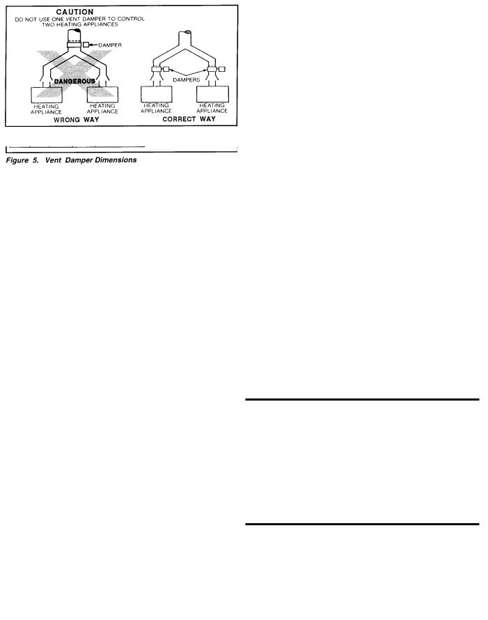
TABLE
|
|
|
|
|
|
|
|
Vent |
|
|
|
|
|
|
Size |
4" |
5" |
6" |
7" |
8" |
|
|
|
|
|
|
|
|
A |
95⁄16" |
105⁄16" |
115⁄16" |
125⁄16" |
135⁄16" |
|
|
|
|
|
|
|
Figure 5. Vent Damper Dimensions
Figure 9.
WARNING—DANGER
Once you have begun vent damper installation procedure, DO NOT restore electric power and gas supply until installation and inspection have been completed (in order to prevent the main burners from operating). DO NOT operate the boiler until the vent damper harness "RECEPTACLE B" is plugged into "MALE PLUG" (as described in the installation instructions), and the vent damper installation and checkout procedures have been completed. Failure to observe this warning may create a hazardous condition that could cause an explosion or carbon monoxide poisoning.
Figure 6. Connecting “RECEPTACLE B” to “MALE PLUG” inside L8148E Aquastat Box for Sentry Packaged “S” and “SX” boilers.
 Loading...