

Skil 7302 Instruction Manual
SM 2610011103 03-10:SM 2610011103 02-10 3/30/10 10:11 AM Page 1
IMPORTANT: IMPORTANT : IMPORTANTE:
Read Before Using Lire avant usage Leer antes de usar
Operating/Safety Instructions
Consignes de fonctionnement/sécurité
Instrucciones de funcionamiento y seguridad
7302
Call Toll Free for
Consumer Information
& Service Locations
Pour obtenir des informations
et les adresses de nos centres
de service après-vente,
appelez ce numéro gratuit
Llame gratis para
obtener información
para el consumidor y
ubicaciones de servicio
1-877-SKIL999 (1-877-754-5999) www.skil.com
For English Version Version française Versión en español
See page 2 Voir page 15 Ver la página 28

SM 2610011103 03-10:SM 2610011103 02-10 3/30/10 10:11 AM Page 2
General Power Tool Safety Warnings
WARNING
!
Read all safety warnings and instructions. Failure to follow the warnings
and instructions may result in electric shock, fire and/or serious injury.
SAVE ALL WARNINGS AND INSTRUCTIONS FOR FUTURE REFERENCE
The term “power tool” in the warnings refers to your mains-operated (corded) power tool or
battery-operated (cordless) power tool.
Work area safety
Keep work area clean and well lit. Cluttered
or dark areas invite accidents.
Do not operate power tools in explosive
atmospheres, such as in the presence of
flammable liquids, gases or dust. Power
tools create sparks which may ignite the dust
or fumes.
Keep children and bystanders away while
operating a power tool. Distractions can
cause you to lose control.
Electrical safety
Power tool plugs must match the outlet.
Never modify the plug in any way. Do not
us e a ny adapter pl ug s with earthe d
(grounded) power tools. Unmodified plugs
and matching outlets will reduce risk of electric
shock.
Avoid body contact with earthed or grounded
surfaces such as pipes, radiators, ranges
and refrigerators. There is an increased risk
of electric shock if your body is earthed or
grounded.
Do not expose power tools to rain or wet
conditions. Water entering a power tool will
increase the risk of electric shock.
Do not abuse the cord. Never use the cord
for carrying, pulling or unplugging the power
tool. Keep cord away from heat, oil, sharp
edges or moving parts. Damaged or entangled
cords increase the risk of electric shock.
When operating a power tool outdoors,
use an extension cord suitable for outdoor
use. Use of a cord suitable for outdoor use
reduces the risk of electric shock.
If operating the power tool in damp locations
is unavoidable, use a Ground Fault Circuit
Interrupter (GFCI) protected supply. Use of
an GFCI reduce the risk of electric shock.
Personal safety
Stay alert, watch what you are doing and
us e co mmon sense w hen opera ting a
power tool. Do not use a power tool while
you are tired or under the influence of drugs,
alcohol or medication. A moment of inattention
while operating power tools may result in
serious personal injury.
Use personal protective equipment. Always
wear eye protection. Protective equipment
such as dust mask, non-skid safety shoes, hard
hat, or hearing protection used for appropriate
conditions will reduce personal injuries.
Prevent unintentional starting. Ensure the
sw itch is in th e o ff-po sitio n b efore
connecting to power source and / or battery
pa ck, picki ng up or carrying the t ool.
Carrying power tools with your finger on the
switch or energizing power tools that have the
switch on invites accidents.
Remove any adjusting key or wrench before
turning the power tool on. A wrench or a
key left attached to a rotating part of the
power tool may result in personal injury.
Do not overreach. Keep proper footing and
balance at all times. This enables better
co ntrol of the power to ol in unexpe ct ed
situations.
Dress properly. Do not wear loose clothing
or jewelry. Keep your hair, clothing and
gloves away from moving parts. Loose
clothes, jewelry or long hair can be caught in
moving parts.
If devices are provided for the connection
of dust extraction and collection facilities,
ensure these are connected and properly
used. Use of dust collection can reduce dust-
related hazards.
Power tool use and care
Do not forc e the power to ol. Use the
correct power tool for your application. The
correct power tool will do the job better and
safer at the rate for which it was designed.
Do not use the power tool if the switch does
not turn it on and off. Any power tool that
ca nn ot be co nt ro ll ed wi th th e swi tc h is
dangerous and must be repaired.
-2-

SM 2610011103 03-10:SM 2610011103 02-10 3/30/10 10:11 AM Page 3
Disconnect the plug from the power source
and/or the battery pack from the power tool
before making any adjustments, changing
accessories, or storing power tools. Such
preventive safety measures reduce the risk of
starting the power tool accidentally.
Store idle power tools out of the reach of
child ren and do n ot allow perso ns
unfamiliar with the power tool or these
instructions to operate the power tool.
Power tools are dangerous in the hands of
untrained users.
Maintain power tools. Check for misalignment
or binding of moving parts, breakage of
parts and any other condition that may
affect the power tool’s o per ati on. I f
damaged, have the power tool repaired
before use. Many accidents are caused by
Safety Rules for Orbital Sanders
Hold power tools by insulated gripping
surfaces when performing an operation
where the cutting tool may contact hidden
wiring or its own cord. Contact with a "live"
wire will make exposed metal parts of the tool
"live" and shock the operator.
Unplug the san de r bef or e cha ng in g
accessories. Accidental start-ups may occur
if sander is plugged in while changing an
accessory.
Use clamps or another practical way to
secure and support the workpiece to a
stable platform. Holding the work by hand
or against your body leaves it unstable and
may lead to loss of control.
Your too l i s equip pe d with a d ust
caniste r, em pty i t f re quently , a ft er
completion of sanding and before storing
the sander. Be extremely careful of dust
disposal, materials in fine particle form may
be explosive. Do not throw sanding dust on
an open fire. Combustion from mixture of
varnishes, lacquers, polyurethane, oil or
water with dust particles can occur if there is
a static discharge, spark introduced in the
box, or excessive heat.
poorly maintained power tools.
Keep cutting tools sharp and clean. Properly
maintained cutting tools with sharp cutting
edges are less likely to bind and are easier to
control.
Use the power tool, accessories and tool
bits etc. in accordance with these instructions,
taking into account the working conditions
and the work to be performed. Use of the
power tool for operations different from those
intended could result in a hazardous situation.
Service
Have your power tool serviced by a qualified
re pa ir pers on using on ly identi ca l
replacement parts. This will ensure that the
safety of the power tool is maintained.
Always wear eye protection and a dust
mask for dusty applications a nd when
sanding overhead. Sanding particles can be
absorbed by your eyes and inhaled easily
and may cause health complications.
Use special precautions when sanding
chemically pressure treated lumber, paint
th at may be lea d base d, or any other
materials that may contain carcinogens. A
suitable breathing respirator and protective
clothing must be worn by all persons entering
the work area. Work area should be sealed
by p la stic s heeting and pe rsons not
protected should be kept out until work area
is thoroughly cleaned.
Do not wet sand with this sander. Liquids
entering the motor housing is an electrical
shock hazard.
Do not use sandpaper intended for larger
sanding pads. Larger sandpaper will extend
beyond the sanding pad causing snagging,
tearing of the paper or kick-back. Extra paper
extending beyond the sanding pad can also
cause serious lacerations.
-3-

SM 2610011103 03-10:SM 2610011103 02-10 3/30/10 10:11 AM Page 4
Additional Safety Warnings
GFCI and personal protection devices like
electrician’s rubber gloves and footwear will
further enhance your personal safety.
Do not use AC only rated tools with a DC
power supply. While the tool may appear to
work, the electrical components of the AC
rated tool are likely to fail and create a hazard
to the operator.
Keep handles dry, clean and free from oil
and grease. Slippery hands cannot safely
control the power tool.
Develop a periodic maintenance schedule
for your tool. When cleaning a tool be
careful not to disassemble any portion of
th e tool sinc e interna l wires may be
misplaced or pinched or safety guard return
sp rings may be improperly moun ted.
Certain cleaning agents such as gasoline,
carbon tetrachloride, ammonia, et c. may
damage plastic parts.
Risk of injury to user. The power cord must only
be serviced by a Skil Factory Service Center or
Autho rized Skil Service Station.
WARNING
!
drilling, and other construction activities
contains chemicals known to cause cancer,
birth defects or other reproductive harm.
Some examples of these chemicals are:
• Lead from lead-based paints,
• Crystalline silica from bricks and cement and
other masonry products, and
• Arsenic and chromiu m from chemicallytreated lumber.
Yo ur ri sk from these expo su re s var ie s,
depending on how often you do this type of
work. To reduce your exposure to these
chemicals: work in a well ventilated area, and
work with approved safety equipment, such as
those dust masks that are specially designed
to filter out microscopic particles.
Some dust created by power
sanding, sawing, grinding,
-4-

0
SM 2610011103 03-10:SM 2610011103 02-10 3/30/10 10:11 AM Page 5
Symbols
IMPORTANT: Some of the following symbols may be used on your tool. Please study them
and learn their meaning. Proper interpretation of these symbols will allow you to operate the
tool better and safer.
Symbol Name Designation/Explanation
V Volts Voltage (potential)
A Amperes Current
Hz Hertz Frequency (cycles per second)
W Watt Power
kg Kilograms Weight
min Minutes Time
s Seconds Time
Diameter Size of drill bits, grinding wheels, etc.
n
0
n Rated speed Manufacturers rated speed
.../min Revolutions or reciprocation Revolutions, strokes, surface speed,
0 Off position Zero speed, zero torque...
1, 2, 3, ... Selector settings Speed, torque or position settings.
I, II, III, Higher number means greater speed
No load speed Rotational speed, at no load
per minute orbits etc. per minute
Infinitely variable selector with off Speed is increasing from 0 setting
Arrow Action in the direction of arrow
Alternating current Type or a characteristic of current
Direct current Type or a characteristic of current
Alternating or direct current Type or a characteristic of current
Class II construction Designates Double Insulated
Construction tools.
Earthing terminal Grounding terminal
Warning symbol Alerts user to warning messages
Li-ion RBRC seal Designates Li-ion battery recycling
program
Ni-Cad RBRC seal Designates Ni-Cad battery recycling
program
Read manual symbol Alerts user to read manual
Wear eye protection symbol Alerts user to wear eye protection
-5-
SM 2610011103 03-10:SM 2610011103 02-10 3/30/10 10:11 AM Page 6
Symbols (continued)
IMPORTANT: Some of the following symbols may be used on your tool. Please study them
and learn their meaning. Proper interpretation of these symbols will allow you to operate the
tool better and safer.
This symbol designates that this tool is listed by Underwriters Laboratories.
This symbol designates that this tool is listed by Underwriters Laboratories,
to United States and Canadian Standards.
This symbol designates that this tool is listed by the Canadian Standards
Association.
This symbol designates that this tool is listed by the Canadian Standards
Association, to United States and Canadian Standards.
This symbol designates that this tool is listed by the Intertek Testing
Services, to United States and Canadian Standards.
This symbol designates that this tool complies to NOM Mexican Standards.
-6-
SM 2610011103 03-10:SM 2610011103 02-10 3/30/10 10:11 AM Page 7
Functional Description and Specifications
!
WARNING
Di sc onnect the plug fro m the pow er source bef or e making any
assembly, adjustments or changing accessories. Such preventive safety
measures reduce the risk of starting the tool accidentally.
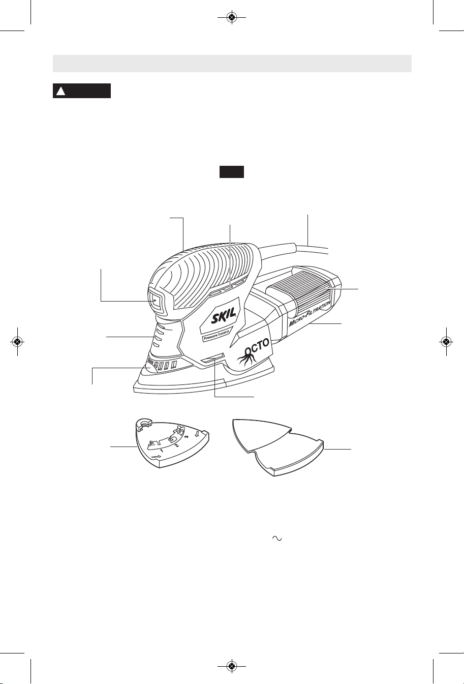
Multi-Finishing Sander
FIG. 1
RUBBERIZED
GRIP
DUST
SEALED
SWITCH
PRESSURE
CONTROL
INDICATOR
LIGHTS
VENTILATION
OPENINGS
CORD
MICROFILTER
MICROFILTER
DUST CANISTER
PAD/PLATE
UNLOCK
BUTTON
ATTACHMENT
SUPPORT
PLATE
VENTILATION
OPENINGS
Model number 7302
Voltage rating 120 V 60Hz
Amperage rating 1.2 A
No load speed n
12,000/min
0
-7-
EXTENSION
PLATE
SM 2610011103 03-10:SM 2610011103 02-10 3/30/10 10:11 AM Page 8
Assembly
!
WARNING
making any assembly, adjustments or
changing acces sories. Such preventive
safety measures reduce the risk of starting
the tool accidentally.
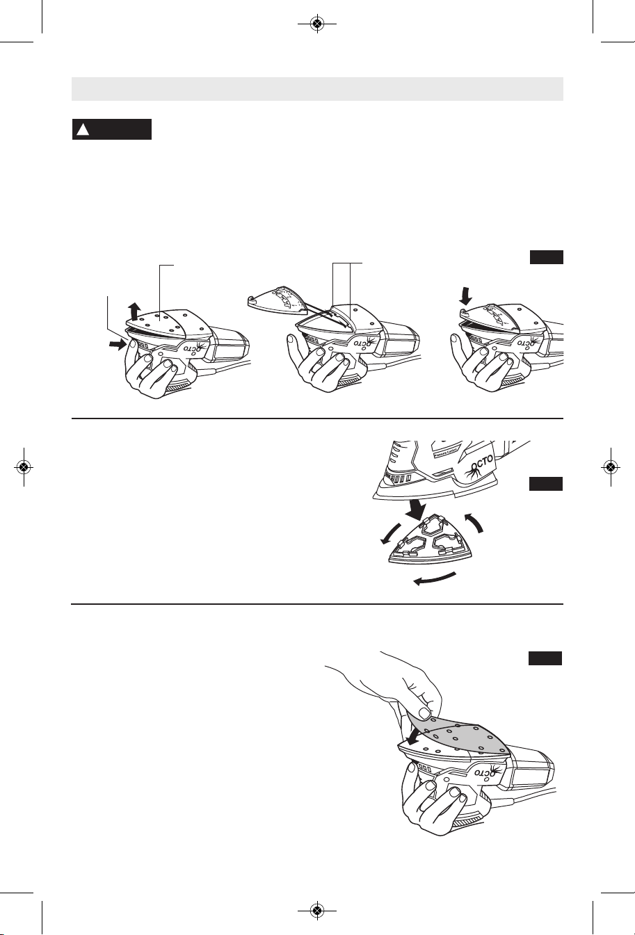
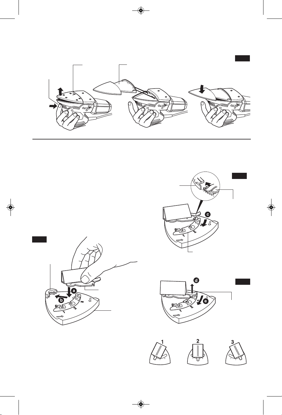
BACKING PAD REMOVAL/INSTALLATION
Your Multi-Finishing sander is equipped with a
hook- and-loop rubber backing pad which may
PAD/PLATE
UNLOCK
BUTTON
For maximum use of abrasive, rotate pad 120
degrees when tip of abrasive becomes worn
Fig. 3).)
Disconnect the plug from
the power source before
BACKING
PAD
ROTATING BACKING PAD
be removed and attached without the need of
addi tional tools.
To remove, press the pad/plate unlock button
and pull the backing pad free from the sander
(Fig. 2.)
To install, engage rear of backing pad under
latched in tool’s recess and press front of
backing pad in place until it engages with a
"Click" sound (Fig. 2).
LATCHES
FIG. 2
FIG. 3
INSTALLING SANDING SHEETS
Your sa nde r uses hook-and-loop backed
sandpaper, which firmly grips the backing pad
when applied with moderate pressure.
To change, mere ly peel off the old sandpaper,
remove dust from the backing pad if necessary,
and press the new sandpaper in place. Be sure
to align the sanding sheet holes with the holes
in the backing pad to allow the dust extraction
system to function (Fig. 4).
After considerable use the backing pad surface
will become worn, and the backing pad must be
replaced when it no longer offers a firm grip. If
you are experiencing premature wear of the
back ing pad facing, decrease the amount of
pressure you are applying during operation of
the tool.
FIG. 4
-8-
SM 2610011103 03-10:SM 2610011103 02-10 3/30/10 10:11 AM Page 9
When sanding in extremely tight areas, such as
EXTENSION PLATE
louvered panels, remove the hook-and-loop
PAD/PLATE
UNLOCK
BUTTON
BACKING
PAD
EXTENSION
ATTACHING THE 3-POSITION
ATTACHMENT SUPPORT PLATE
Yo ur sand er also feature s a 3-po sitio n
attachment support plate. The attachment
support plate allows you to easily attach and
change the position of accessories provided.
Press the pad/plate unlock button and pull the
backing pad free of the sander. Engage rear of
3-position attachment support plate in its recess
and press front of pad in place until it engages
with a "Click" sound. (Fig. 2).
ATTACHING ACCESSORIES
1. Insert round portion of the attachment into
the mounting boss from the side of pad (Fig. 6).
FIG. 6
backing pad and attach the extension plate
provided (Fig. 5).
FIG. 5
PLATE
To change position of attachment, simply lift
release tab, swing attachment to desired notch
and release tab to secure attachment (Fig. 8).
FIG. 7
ADJUSTMENT
RAIL
REAR END OF
ATTACHMENT
PLATE
MOUNTING
BOSS
ATTACHMENT
ATTACHMENT
SUPPORT
PLATE
2. Swing attachment in direction of arrow C flat
against pad until rear portion of attachment
slides underneath the the adjustment rail
(Fig. 7).
3. Lift up on release tab, swing attachment to
notch and release tab.
ADJUSTMENT
RAIL
FIG. 8
RELEASE
TAB
-9-

SM 2610011103 03-10:SM 2610011103 02-10 3/30/10 10:11 AM Page 10
Operating Instructions
ROCKER “ON/OFF” SWITCH
TO TUR N THE TOOL "ON" de press the
dust-protected switch to the number “I” position
(Fig. 1).
TO TURN THE TOOL "OFF": depress switch
to the number “0” position.
Always hold the sander off the work when
turning the switch “ON” or “OFF”. Contact the
work with the tool after sander has reached its
full speed and remove it from the work before
turning the switch “OFF”. Operating in this
manner will prolong switch and motor life and
will greatly increase the quality of your work.
MICROFILTER DUST CANISTER
The integral dust extraction system collects
sanding dust in canister supplied with your
sander. For maximum efficiency, the dust
canister should be emptied frequently during
operation.
WARNING
!
frequently, after completion of sanding and
before storing the sander. Be extremely
careful of du st disposal, materials in fine
particle form may be explosive. Do not throw
sanding dust on an open fire. Combustion
fr om mixture of varn ishes, lacq ue rs,
polyurethane, oil or water with dust particles
can occur if there is a static discharge, spark
introduced in the box, or excessive heat.
Your tool is equipped with a
du st canist er, empt y it
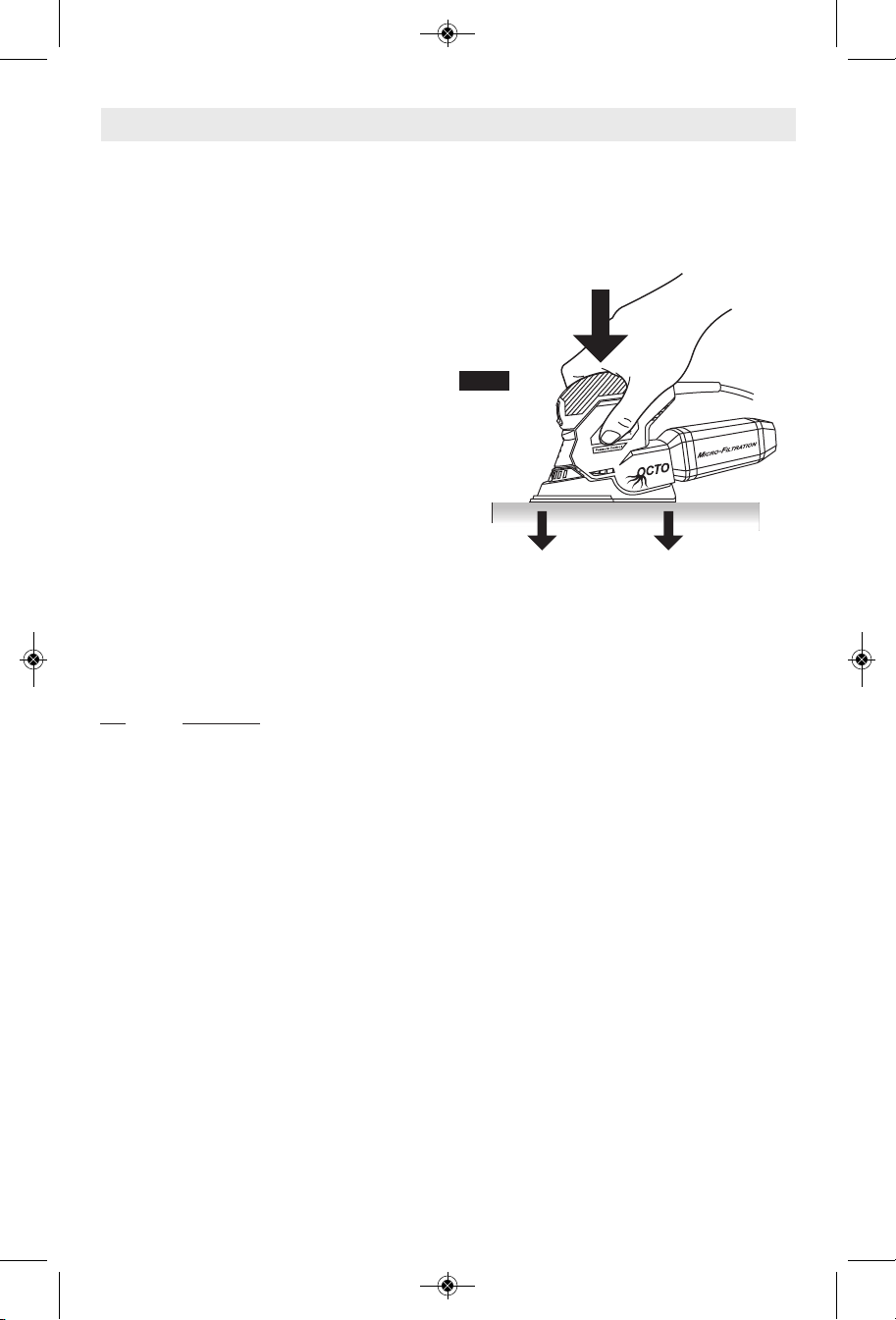
Your tool is equipped with pressure control
PRESSURE CONTROL
indicator lights. The indicator lights will let you
know if you are applying the proper amount of
pr essur e duri ng o peratio n. If the green
indicator lights are illuminated you are applying
the correct amount of pressure. If the red
indicator light illuminates you are applying too
much pressure and you need to apply less
pressure (Fig. 9).
Pressure control feature is intended for use
with standard Delta backing pad.
REMOVING AND INSTALLING
DUST CANISTER
To remove dust canister, simply pull away from
the tool (Fig. 9).
To install dust canister, align dust port with
hole in canister and push canister onto tool.
CLEANING AND EMPTYING
THE DUST CANISTER
Knock excess dust out of the microfilter, or
remove dust with your fingers or a soft brush.
You may notice that all the dust may not
come out of the canister. This will not affect
sanding performance but will reduce dust
collection efficiency.
NOTE: Do not wash the micro filter with soap
and water. Dust may become more firmly
lodged in the pores, which will reduce dust
collection, and damage the micro filter.
FIG. 9
EXCESSIVE
PRESSURE
OPTIMAL
PRESSURE
-10-
DUST PORT
MICROFILTER
MICROFILTER
DUST CANISTER
SM 2610011103 03-10:SM 2610011103 02-10 3/30/10 10:11 AM Page 11
Tool Tips
This tool is particularly suitable for one hand ed
operation, and access to corners and edges
that are otherwise difficult to reach and require
hand sanding. Profiles and grooves may be fin ished using the tip or edge of the selected
attachment, which should occasionally be
rotated during use to distribute the wear on the
attachment and backing pad surface.
Always be certain that smaller workpieces are
securely fastened to a bench or other support.
Larger panels may be held in place by hand on
a bench or sawhorses.
SANDING: Open-coat aluminum oxide sanding
sheets are recommended for most wood or
metal sand ing applications, as this synthetic
material cuts quickly and wears well. Some
ap plica tions , such as me ta l fin ishing or
cleaning, require spe cial abrasive pads which
are available from your dealer. For best results,
use sanding and polishing accessories which
ar e of sup erior quality a nd a re c arefu lly
selected to produce professional quality results
with your sander.
The following suggestions may be used as a
gen eral guide for abrasive selection, but the
best re sults will be obtained by sanding a test
sample of the workpiece first.
Grit
Coarse For rough wood or metal sanding,
Medium For general wood or metal sanding
Fine For final finishing of wood, metal,
Extra fine For final sanding of bare wood,
With the workpiece firmly secured, turn tool on
as described above. Contact the work with the
tool after the sander has reached its full speed,
and remove it from the work before switching
the tool off. Operating your sander in this
manner will pro long switch and motor life, and
greatly increase the quality of your work.
Move the sander in long steady strokes parallel
to the grain using some lateral motion to
Application
and rust or old finish removal.
plaster and other surfaces.
smoothing old paint, or preparing a
finished surface for recoating.
overlap the strokes by as much as 75%. DO
NOT apply exces sive pressure — let the tool
do the work. Ex cessive pressure will result in
poor handling, vibration, and unwanted sanding
marks (Fig. 10).
FIG. 10
If the surface is rough, begin with coarser grits
and then complete the surfacing with medium
and fine abra sives. To avoid uneven results, do
not skip more than one grit size when going
from coarser to finer, and do not sand in one
area for too long. When the job is completed,
gently lift the tool from the work surface and
slide switch to the "OFF" position.
POLISHING: Your Multi-finishing sander may
be fit ted with option al abrasive mes h or
polishing pads to polish or remove scratches or
co rrosi on from meta l, pain ted, or oth er
surfaces. The tool is oper ated in much the
same way as when sanding, but the following
points should be observed;
Use light pressure and a circular or overlapping
mo tion to remove scratches and corrosion or
pol ish a surface. If using a compound, use only
as much as necessary and do not use the dust
ex trac tion feature.
Wh en working in v ery confi ned areas o r
louvered pa nels, the pad extension plate
should be used.
Clean the buffing or mesh pads with mild deter gents and warm water. DO NOT use solvents.
-11-

SM 2610011103 03-10:SM 2610011103 02-10 3/30/10 10:11 AM Page 12
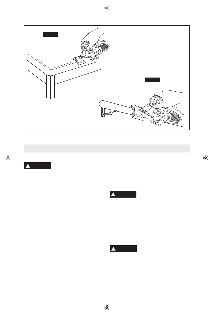
Application Advise
Use the tool with its standard backing pad for
la rge work surf aces, cor ners and edges
(Fig. 11).
Use the tool with special sanding attachments
for hard to reach areas (Fig. 12).
FIG. 11
FIG. 12
The flexible sanding attachment is intended for
rounding edged surfaces (Fig. 13a).
The flexible sanding can also be used on all
rounded surfaces with a maximum diameter of
10 cm (Fig. 13b).
-12-
SM 2610011103 03-10:SM 2610011103 02-10 3/30/10 10:11 AM Page 13
FIG. 13a
FIG. 13b
Maintenance
Service
!
WARNING
per so n nel may result in misplacing of
inter nal wires and compon ents which
co ul d ca us e se ri ou s ha za rd . We
recommend that all tool service be performed
by a Skil Factory Service Center or Autho rized
Skil Service Station.
Your Skil tool has been properly lubricated
and is ready to use. It is recommended that
tools with gears be regreased with a special
gear lubricant at every brush change.
The brushes and commutator in your tool
have been engineered for many hours of
de pe nd ab le service. To maintain peak
efficiency of the motor, we recommend every
two to six months the brush es be examined.
On ly gen ui ne Ski l replac e ment br ushes
specially designed for your tool should be
used.
After about 300-400 hours of operation, or at
every second brush change, the bearings
Pr event ive ma intenance
performed by unauthorized
TOOL LUBRICATION
CARBON BRUSHES
BEARINGS
should be replaced at Skil Factory Service
Center or Au thorized Skil Service Station.
Bearings which become noisy (due to heavy
load or very abrasive material cut ting) should
be replaced at once to avoid overheating or
motor failure.
Cleaning
!
WARNING
th e power supp ly be fo re cl ea ning or
performing any main tenance. The tool may
be cleaned most effectively with compressed
dry air. Always wear safety gog gles when
cleaning tools with compressed air.
Ventilation openings and switch levers must
be kept clean and free of foreign matter. Do
not at tempt to cl ean by inserting poin ted
objects through openings.
!
CAUTION
plastic parts. Some of these are: gasoline,
carbon tetrachlo ride, chlo rinated cleaning
solvents, ammonia and house hold detergents
that contain ammonia.
To avoid accidents always
dis connect the tool from
Ce rtain cleanin g agen ts
an d so l v en ts da ma ge
-13-

SM 2610011103 03-10:SM 2610011103 02-10 3/30/10 10:12 AM Page 14
Accessories
!
WARNING
If an ex te nsion cord is
necessa ry , a co rd with
adequate size conductors that is capable
of carrying the current necessary for your
tool mu st be used. This wi ll pr ev ent
excessive voltage d rop, loss of power or
overheating. Grounded tools must use 3wire extension cords that have 3-prong plugs
and receptacles.
NOTE: The smaller the gauge number, the
heav i er the cord.
*(8) Attachments
*(32) Pieces of abrasives
RECOMMENDED SIZES OF EXTENSION CORDS
120 VOLT ALTERNATING CURRENT TOOLS
3-6
6-8
8-10
10-12
12-16
Cord Size in A.W.G.
Cord Length in Feet Cord Length in Meters
25 50 100 150 15 30 60 120
18 16 16 14 0.75 0.75 1.5 2.5
18 16 14 12 0.75 1.0 2.5 4.0
18 16 14 12 0.75 1.0 2.5 4.0
16 16 14 12 1.0 2.5 4.0 —
14 12 —— ————
Tool’s
Ampere
Rating
(*= standard equipment)
(**= optional accessories)
*(1) Carrying bag
Trouble Shooting
WARNING
!
PROBLEM 1. Power cord is not plugged in.
REMEDY 1. Plug tool into power source.
PROBLEM 1. Extension cord has insufficient gauge or is too long.
REMEDY 1. Replace with adequate extension cord (Page 14).
Read instruction manual first! Remove plug from the power source before
making adjustments or assembling accessories.
TROUBLE: TOOL WILL NOT START
2. Power source fuse or circuit breaker tripped.
3. Cord damaged.
4. Burned out switch.
2. Replace fuse or reset tripped circuit breaker. (If the product repeatedly causes
the circuit or fuse to trip/blow, discontinue use immediately and have it serviced by
an Authorized Skil Service Center or Service Station.)
3. Inspect cord for damage. If damaged, have cord replaced by an Authorized Skil
Service Center or Service Station.
4. Have switch replaced by an Authorized Skil Service Center or Service Station.
TROUBLE: TOOL DOES NOT COME UP TO SPEED
2. Low house voltage.
2. Contact your electric company.
Wire Sizes in mm
2
-14-
 Loading...