

Page 1

S
S
S
E
CK
%DECK%ANC H E R S %
CK%ANC H E R
%DECK%ANC H E R S %
ECK%ANC H E R
DECK ANCHORS
%DECK%ANC H E R S %
ECK%ANC H E R
DECK%ANC H E R S %DECK%ANC H E R S % DECK%A N C H E R S %DECK%ANC H E R S % DECK%ANC HERS % D E C K %ANCHERS% DECK%A N C
Page 2

SECTIO
T
l
.
l
n
.
a
CH
TE
n
svent
y
t
c
l
et
T
x
e
s
23/4
dle
s
SPECIFICATION & DESIGN MANUAL(
METAL DECK ANCHOR AND WOOD DECK ANCHOR
PRODUC T(DESCRIPTION
Metal Deck Anchor concrete inserts are designed for installation in and through metal
composite deck (i.e. “pan-deck”) used to support newly poured concrete or roof slabs.
After pre- drilling the deck and installation, the protective sleeve of the insert protrudes below
the surface of the deck allowing overhead attachment of steel threaded rod in sizes ranging from
1/4" to 7/8" in diameter. The sleeve prevents sprayed
dampening products from clogging the internal threads of the insert. It also prevents burying,
masking or losing the insert location. The unique, six sided impact plate o
rotation within the concrete as a steel threaded rod is being installed.
Wood Deck Anchor concrete inserts are installed onto wooden forms used to support newly
poured concrete slabs, roof slabs or walls. When the forms are stripped, the color-coded
is visibly embedded in the concrete surface. The inserts allow the attachment of steel
threaded rod or threaded bolts
sided impact plate o
threaded bolt is being installed.
A coil thread design is available for upon request in 1/2" and 3/4" sizes for
forming applications.
ers resistance to rotation within the concrete as a steel threaded rod or
in sizes ranging from 1/4" to 3/4" in diameter. The unique six
Wood Deck Anchor
GENERAL(APPLICATIONS(AND(USES
t Hanging Pipe and Sprinkler Systems t Suspending Conduit and Cable Trays
t Lighting Systems and Overhead Utilities t HVAC Ductwork and Strut Channels
tt
Suspended Ceilings
Concrete Framework
ionnndh
d
evef the
ade
repr material and acoustical
material andacoustical
insertl
la
tall
n
ormssed tosupport
r
l
iam
a ste
que
nduitn
rk
ndruthannel
ugh
e
nsert
ers resistance to
ed
ttach
/
oofslabs.
trudeselow
angi
sistan
h
uniqi
a
ewly
tee
ng
for
SECTION CONTENTS Page No.
General Information ................. 01
Generlnformation
ateria
Material
Stee
Steel
Installatio
Installation
Performance Data...................... 05
rformance Dat
NTEN
............. 02
...........
................... 03
..................3
........ 04
......
Metal Deck Anchor
FEATURES(AND(BENEFITS
t Higher load values due to full thread engagement
t Color coded by size for all trades
t Low overall installed cost
Wood Deck Anchor
ANCHOR MATERIALS
AN
Carbon Steel and Engineered Plastic
IAL
ROD/ANCHOR SIZE RANGE (TYP.)
1/4" to 7/8" threaded rod for Metal
Deck Anchor Concrete Inserts
1/4" to 3/4" threaded rod for Wood
Deck Anchor Concrete Inserts
1/2" and 3/4" coil thread for Wood
Deck Anchor Concrete Inserts
SUITABLE BASE MATERIALS
Normal-Weight Concrete
Structural Lightweight Concrete
24110(South(Peculiar(Drive( PECULIAR,(MO(64078 800.821.3944( FAX:(800.758.5950( (WWW(SIOUXCHIEF.COM
01
Page 3

!"#$%&%$'(%)* + ,#!%-* .'*/'01
.'(#2%'0 !"#$%&%$'(%)*!
Metal Deck Anchor
Anchor Component Component Material
Insert Body AISI 1008 Carbon Steel
Flange AISI 1008 Carbon Steel
Spring Steel Music Wire
Zinc Plating ASTM B 633 (Yellow Dichromate)
Protective Sleeve Engineered Plastic
!(##01!"#$%&%$'(%)*!
Material Properties for Threaded Rod
Steel Description
Standard carbon rod
High strength carbon rod
Stainless Rod
(Type 304 / 316 SS)
(ASTM)
A 36
A 307, Grade C
A 193, Grade B7
F 593, Condition CW
Rod Diameter
3/8 thru 2 1/2
3/4 thru 1 1/2
Allowable Steel Strength for Threaded Rod
Nominal
Anchor
Diameter
d
in.
(mm)
1/4 0.0491 940 940 2,160 1,210 485 485 1,030 625
(6.4) (1.2) (4.2) (4.2) (9.7) (5.4) (2.2) (2.2) (4.6) (2.8)
3/8 0.1104 2,115 2,115 4,375 3,630 1,090 1,090 2,255 1,870
(9.5) (2.8) (9.5) (9.5) (19.7) (16.3) (4.9) (4.9) (10.1) (8.4)
1/2 0.1963 3,755 3,755 7,775 6,470 1,940 1,940 4,055 3,330
(12.7) (5.0) (16.9) (16.9) (35.0) (29.1) (8.7) (8.7) (18.2) (15.0)
5/8 0.3068 5,870 5,870 12,150 10,130 3,025 3,025 6,260 5,210
(15.9) (7.8) (26.4) (26.4) (54.7) (45.6) (13.6) (13.6) (28.2) (23.4)
3/4 0.4418 8,455 8,455 17,495 12,400 4,355 4,355 9,010 6,390
(19.1) (11.2) (38.0) (38.0) (78.7) (55.8) (19.6) (19.6) (40.5) (28.8)
7/8 0.6010 11,510 11,510 23,810 16,860 5,930 5,930 12,265 8,680
(22.2) (15.3) (51.8) (51.8) (107.1) (75.9) (26.7) (26.7) (55.2) (39.1)
Area of
Rod
in.
(mm)
ASTM
A36
lbs.
(kN)
Allowable Tension
ASTM
A307
Grade C
lbs.
(kN)
Grade B7
ASTM
A193
lbs.
(kN)
Wood Deck Anchor
Anchor Component Component Material
Insert Body AISI 1008 Carbon Steel
Flange Engineered Plastic
Zinc Plating ASTM B 633 (Yellow Dichromate)
(inch)
All
3/8 thru 4
3/8 thru 5/8
ASTM
F593
304/316 SS
lbs.
(kN)
Minimum Yield
Strength, f
36.0
36.0
105.0
65.0
45.0
ASTM
A36
lbs.
(kN)
(ksi)
y
Allowable Shear
ASTM
A307
Grade C
lbs.
(kN)
Minimum Ultimate
Strength, f
58.0
58.0
120.0
100.0
85.0
ASTM
A193
Grade B7
lbs.
(kN)
304/316 SS
(ksi)
u
ASTM
F593
lbs.
(kN)
02
%*!('00'(%)* !"#$%&%$'(%)*!
Metal Deck Anchor
Dimension
Metal Hole Saw Diameter (in.) 13/16 13/16 13/16 1 3/16 1 3/16 1 3/16
Drilling Speed (rpm)
Height of Spring (in.)
Insert Thread Length (in.)
Length of Sleeve (in.)
Thread Size, UNC
Overall Length (in.)
Steel Flange Thickness (in.)
1/4” 3/8”
700-900 700-900 700-900 500-700 500-700 500-700
2 2 2 2 2 2
3/8 5/8 11/16 15/16 1 1/8 1 5/16
3 3/8 3 3/8 3 3/8 3 3/8 3 3/8 3 3/8
1/4-20 3/8-16 1/2-13 5/8-11 3/4-10 7/8-9
5 5/16 5 5/16 5 5/16 5 5/16 5 5/16 5 5/16
5/64 5/64 5/64 5/64 5/64 5/64
Rod/Anchor Size
1/2” 5/8” 3/4” 7/8”
Wood Deck Anchor
Dimension
Insert Thread Length (in.)
Plastic Flange Dia. (in.)
Plastic Flange Thickness (in.)
Thread Size, UNC
Overall Length (in.)
(in.)
345561!789:1";<8=>?@1,@>A;1 "#$/0%'2B1.)1C46DE E66FE35FGH441 &'IJ1E66FDKEFKHK61 1LLL1!%)/I$M%#&F$).
1/4” 3/8”
3/8 5/8 11/16 15/16 1 1/8
1 3/8 1 3/8 1 3/8 1 5/8 1 5/8
7/64 7/64 7/64 7/64 7/64
1/4-20
1 7/8 1 7/8 1 7/8 1 7/8 1 7/8
3/4 3/4 3/4 3/4 3/4
3/8-16
Rod/Anchor Size
1/2”
1/2-13
5/8” 3/4”
5/8-11 3/4-10
Page 4

INSTALLATION GUIDELINES
Prior to pouring concrete, use the
recommended diameter metal hole saw
to drill a hole through the metal deck
at the location the insert is needed.
Typically, inserts are installed in the
for easier access during installation.
However, it is also acceptable to install
metal deck.
From the topside of the metal deck,
place the Metal Anchor Insert's
color-coded, plastic protective sleeve
through the pre-drilled hole. The
spring-loaded impact plate and cause
it to stand upright. Either step on the
anchor with your foot or using a hand
held hammer, strike the head of the
anchor with enough force to cause the
tapered portion of the protective plastic
sleeve to push through the metal deck,
clamping the deck surface between the
are installed, concrete pouring may
commence. The clamping pressure
generated by the spring keeps the
sleeve perpendicular to the deck
surface during the pour.
Either before or after the concrete
has been placed, tap the appropriate
diameter steel thr eaded rod or
threaded bolt through the opening
at the end of the plastic sleeve and
screw into the internally threaded
insert. Minimum thread engagement
should be one anchor diameter.
Concrete should be allowed
to properly cure and achieve
its design compressive strength
before loading the threaded rod
with the intended assembly.
For safety purposes, it is best to wait
until the insert is ready to be put in
service before screwing the steel
threaded rod into place.
Chuck Carbide Hole Saw
Drill Deck Holes
Push Anchor into Place
Set by Stepping on Anchor
SPECIFICATION & DESIGN MANUAL
Wood Deck AnchorMetal Deck Anchor
Prior to pouring concrete over the
wood form, place the Deck Anchor
on the surface of the wood form at
the desired location. Strike the impact
plate of the insert with a hand held
hammer, until the plastic color-coded
When all inserts are installed, concrete
pouring may commence.
After the wood forms are removed,
Carefully remove any unbroken
nails by swiping with a hammer.
Eye protection should be worn when
appropriate diameter steel rod or
threaded bolt can be inserted into the
into the internally threaded insert.
Minimum thread engagement
should be one anchor diameter.
Concrete should be allowed to
properly cure and achieve its design
compressive strength before loading
the rod or threaded bolt with the
intended assembly.
For safety purposes, it is best to wait
until the insert is ready to be put in
service before screwing the steel
threaded rod into place.
Set Wood Deck Anchor
into Place
Hammer in Insert
Pour Co ncret e
Pour Con cret e.
Then Ins tall Rod
24110 South Peculiar Drive PECULIAR, MO 64078 800.821.3944 FAX: 800.758.5950 WWW SIOUXCHIEF.COM
Install Rod
03
Page 5
SPECIFICATION & DESIGN MANUAL
PERFORMANCE DATA
Ultimate and Allowable Load Capacities for Metal Deck Anchor Inserts Installed in Structural Lightweight
Concrete over Metal Deck
Rod/Insert
Diameter
d
in.
(mm)
1/4
(6.4)
3/8
(9.5)
1/2
(12.7)
5/8
(15.9)
3/4
(19.1)
7/8
(22.2)
Embedment
Depth
h
v
in.
(mm)
2
(50.8)
2
(50.8)
2
(50.8)
2
(50.8)
2
(50.8)
2
(50.8)
1,2,3,4
Flute
Location
in
Deck
Upper
Lower
Upper
Lower
Upper
Lower
Upper
Lower
Upper
Lower
Upper
Lower
Minimum
Insert
Spacing
in.
(mm)
9
(228.6)
9
(228.6)
9
(228.6)
9
(228.6)
9
(228.6)
12
(304.8)
9
(228.6)
9
(228.6)
12
(304.8)
9
(228.6)
9
(228.6)
12
(304.8)
Minimum
End
Distance
in.
(mm)
12
(304.8)
12
(304.8)
12
(304.8)
12
(304.8)
12
(304.8)
12
(304.8)
f´
≥
3,000 psi (20.7 MPa)
c
Ultimate Load Allowable Load
Tension Shear Tension Shear
lbs. lbs. lbs. lbs.
(kN) (kN) (kN) (kN)
4,450 2,500 1,115 835
(20.0) (11.3) (5.0) (3.8)
3,320 2,500 830 625
(14.9) (11.3) (3.7) (2.8)
5,750 3,350 1,915 1,115
(25.9) (15.1) (8.6) (5.0)
3,320 3,350 830 840
(14.9) (15.1) (3.7) (3.8)
7,110 3,350 2,370 1,115
(32.0) (15.1) (10.7) (5.0)
3,320 3,350 830 840
(14.9) (15.1) (3.7) (3.8)
8,810 3,350 2,935 1,115
(39.6) (15.1) (13.2) (5.0)
3,960
3,960 3,350 990 840
(17.8) (15.1) (4.5) (3.8)
8,810 3,350 2,935 1,115
(39.6) (15.1) (13.2) (5.0)
3,960
3,960 3,350 990 840
(17.8) (15.1) (4.5) (3.8)
8,810 3,350 2,935 1,115
(39.6) (15.1) (13.2) (5.0)
3,960
3,960 3,350 990 840
(17.8) (15.1) (4.5) (3.8)
–
–
–
990
)5.4()8.7 1(
990
)5.4()8.7 1(
990
)5.4()8.7 1(
–
–
–
04
2. The allowable working load must be the lesser of the insert capacity or the steel strength of the threaded rod.
4. Allowable loads for anchors to resist short-term loads such as earthquake or wind may be increased by 33-1/3 percent for the duration of the load where permitted by code.
24110 South Peculiar Drive PECULIAR, MO 64078 800.821.3944 FAX: 800.758.5950 WWW SIOUXCHIEF.COM
Page 6

PERFORMANCE DATA
SPECIFICATION & DESIGN MANUAL
Ultimate and Allowable Load Capacities for Wood Deck Anchor Inserts Installed
in Normal-Weight Concrete
1,2,3,4,5
Minimum Concrete Compressive Strength (f´c)
Rod/
Insert
Embed.
Depth
Diameter
d
in.
(mm)
(mm)
1/4
(6.4)
(50.8)
3/8
(9.5)
(50.8)
1/2
(12.7)
(50.8)
5/8
(15.9)
(50.8)
3/4
(19.1)
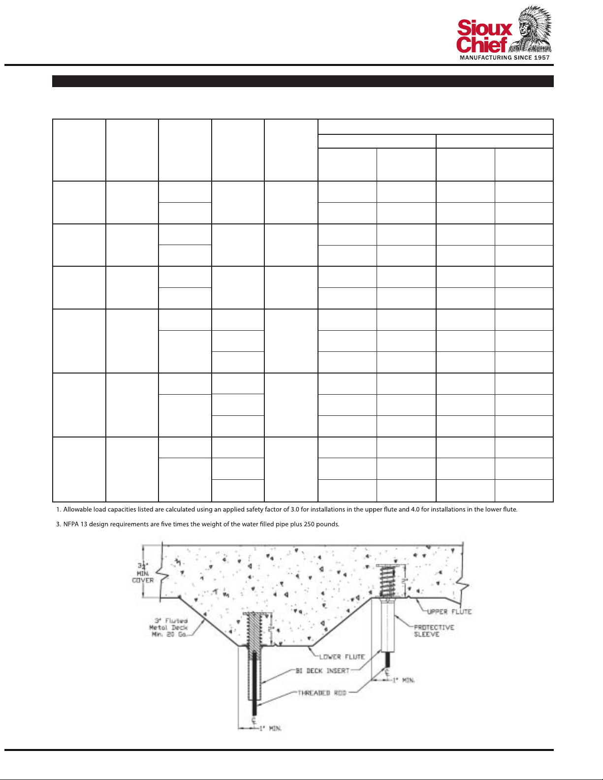
1. Allowable load capacities listed are calculated using an applied safety factor of 3.0.
2. The allowable working load must be the lesser of the insert capacity or the steel strength of the threaded rod.
3. Linear interpolation may be used to determine ultimate loads for intermediate compressive strengths.
5. Allowable loads for anchors to resist short-term loads such as earthquake or wind may be increased by 33-1/3 percent for the duration of the load where permitted by code.
(50.8)
in.
h
2
2
2
2
2
Minimum
Insert
Spacing
v
(mm)
(228.6) (152.4) (20.9) (7.0) (38.0) (12.7)
(228.6) (152.4) (20.9) (7.0) (33.1) (11.0)
Minimum
End
Distance
in.
in.
(mm)
964,650
964,650
lbs. lbs. lbs. lbs. lbs. lbs. lbs. lbs.
(kN) (kN) (kN) (kN) (kN) (kN) (kN) (kN)
3,000 psi (20.7 MPa) 4,500 psi (31.1 MPa)
Ultimate Load
Allowable Load
–
–
1,550
1,550
–
–
Ultimate Load Allowable Load
8,440
7,350
–
–
2,815
2,450
–
–
Ultimate and Allowable Load Capacities for Wood Deck Anchor Inserts Installed in Structural
Lightweight Concrete
Rod/Insert
Diameter
d
in.
(mm)
1/4
(6.4)
3/8
(9.5)
1/2
12.7
(
)
5/8
15.9
(
)
3/4
(19.1)
1. Allowable load capacities listed are calculated using an applied safety factor of 3.0.
2. The allowable working load must be the lesser of the insert capacity or the steel
strength of the threaded rod.
plus 250 pounds.
4. Allowable loads for anchors to resist short-term loads such as earthquake or wind
may be increased by 33-1/3 percent for the duration of the load where permitted
by code.
Embedment
1,2,3,4
Minimum
Depth
Insert
Spacing
h
v
in.
(mm)
2
(
50.8) (228.6) (152.4) (19.2) (7.6) (6.4) (2.5)
2
(
50.8) (228.6) (152.4) (19.2) (23.8) (6.4) (7.9)
2
(
50.8) (228.6) (152.4) (19.2) (32.3) (6.4) (10.8)
2
(50.8)
2
(50.8)
in.
(mm)
9 6 4,270 1,680 1,425 560
9 6 4,270 5,280 1,425 1,760
9 6 4,270 7,180 1,425 2,395
9 6 4,600
(228.6)
12 9 4,600 7,590 1,535 2,530
(304.8) (228.6) (20.7) (34.2) (6.9) (11.4)
9 6 4,600
(228.6)
12 9 4,600 7,590 1,535 2,530
(304.8) (228.6) (20.7) (34.2) (6.9) (11.4)
Minimum
End
Distance
in.
(mm)
(152.4)
(152.4)
f´
≥
3,000 psi (20.7 MPa)
c
Ultimate Load Allowable Load
Tension Shear Tension Shear
lbs. lbs. lbs. lbs.
(kN) (kN) (kN) (kN)
(20.7)
(20.7) (6.9)
–
–
1,535
(6.9)
1,535
–
–
24110 South Peculiar Drive PECULIAR, MO 64078 800.821.3944 FAX: 800.758.5950 WWW SIOUXCHIEF.COM
05
 Loading...