

Singer 71K101 Instruction Manual

•
INSTRUCTIONS
SEWING.
FOR
MAKING
WITH
FOR
USING
AND
SINGER
71K101
STRAIGHT
SQUARE
ADJUSTING
MACHINE
BUTTONHOLES
BARRED
ENDS

USE
SINGER*
OILS
They
The
TYPE
When
stain on
TYPE
type
TYPE
and
insure
following
B —
an oil is
fabrics,
D —
OTHER
E —
For
stitching
required.
F -
For oil lubricated motors and plain bearings in
tables
NOTE;
1 gallon
LUBRICANTS
freedom
longer life to sewing equipment
are ihe
MANUFAaURING
MANUFACTURING
THREAD
lubricating
fabricsorleather
MOTOR
and
All of the
and
from
lubricating
correct
lubricants
MACHINE
desired
which
will
produceaminimum
even after a long period of storage,
MACHINE
SINGER*
LUBRICANT
the
needle
LUBRICANTS
threadofsewing
whereathread
OIL
transmitters.
above
5 gallon cans.
oils
ore
trouble
for
OIL,
OIL,
and give
this
machine:
HEAVY
HEAVY
machines
available in 1 quart,
GRADE
of
use:
GRADE
lubricant
power
for
is
GEAR
BALL BEARING LUBRICANT
1
LUBRICANT
This
specially
lubrication on manufacturing sewing machines.
This
pure
of
ball
electric
etc.
Furnished In 1 lb.
prepared greaseIsrecommended
0'reaseisspecially
bearings
transmitters,
for gear
designed
and
ball
thrust
ball bearing hangers of power tables,
and4lb.
for the
bearingsofmotors
tins.
lubrication
and
Form
(861)
K6441
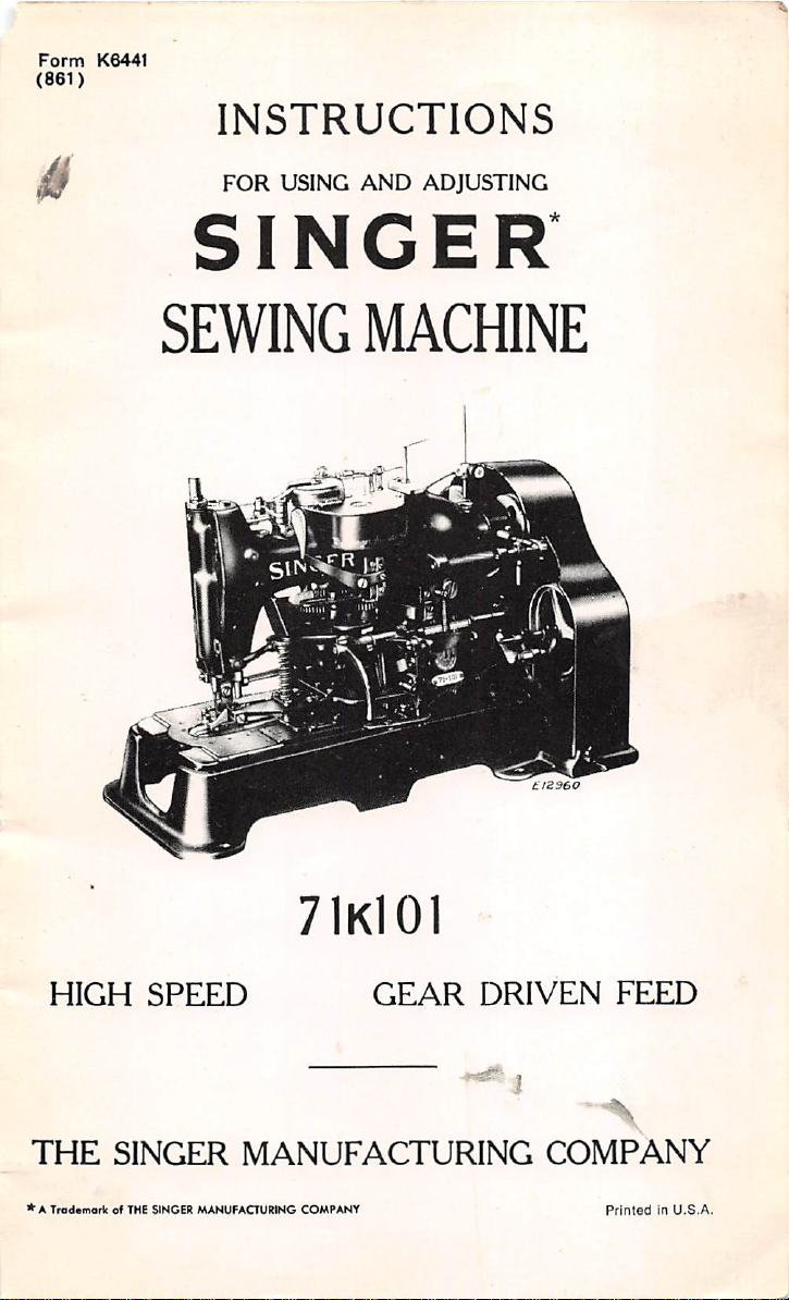
INSTRUCTIONS
FOR
USING
AND
ADJUSTING
SINGER
SEWING MACHINE
HIGH
THE
*A
Trademark
SPEED
SINGER
of THE SINGER
MANUFACTURING
7IkI0I
GEAR
MANUFACTURING
COMPANY
DRIVEN
FEED
COMPANY
PrintedinU.S.A.

Copyright
under
international
Copyright
Union

DESCRIPTION
Machine
in cotton, linen,
This
which
stitches
conditions.
71k101
is designed for making
rayon
and
silk fabrics,
machine has a positive,
controls
are
the
movement
uniformly spaced around
of
gear
the
knit
driven,
work
the
goods,etc.
By simply changing the stitch regulating gear,
of
stitchesinthe
of stitch regfulating
The
stop
of
gears
havingaratio
stop
camtoone-halfofthe
cam
has
two
othersothat
stop cam
rod
extra
to
stop
turns
drops
into
long spiral
without
Machine
barred
threads
to1inch
Check
Washer
ends,
and
long
Complete
40045
be furnished, on
can
be supplied additionallyatan
Unless
fitted
J
inch
Whip
by
substituting
the
machine;
otherwise
with
a f inch knife
buttonholes.
Stitch
249633
40028
Stitch
For
Machine
249682-30
249725-36
249727-40
249744-45
For
other
buttonhole
gears
canbevaried,asdesired.
on page 16.)
motion mechanism of
of 2 to 1 for
speed of
stop
notches located diametrically opposite each
when
the
stop
motion
only a
one of
part
of a revolution before
the
notchestostop
springinthe
shock.
71k101
the
makes
the
hole
being
buttonhole
can
alsobemadeonthis
249758,
are
Clamp
purl
cut
andaknifeofthe
order,
in place of
ordered,
Buttonholes
the
following
Shuttle
Shuttle
Bobbin
Body
Regulating
7IK10I
Teeth
"
"
"
gears
and
the
and
three
canbeproducedonabove
parts
Case complete
Gears for
specifications see
this
machine includes a
reducing
the
-sewing shaft.
mechanism is engaged,
the
stop cam
stitch
gear
buttonholes
from f to f inch long.
cut
after
stitching.
machinebyusing
Check
required
the
extra
71k101
Holder
length.
regular
charge.
machine
additional
in placeofsimilar
Whip
Stitch
page
straight
clamp
buttonholes
intermittent
so
that
feed
the
buttonhole under all
the
number
(See
list
pair
the
speed of
The
the
stop
the
the
interlocking
machine. A single,
helps the machine
with
square
Both
Buttonholes
271946,
These
parts
up
Clamp
Fibre
will
equipment,orthey
willbesent
knives for §, ^
out
and
machine
parts
on
16.

The
When
should
The
the
edge of
the
leg
maximum
the
machines
turn
To
speed recommended is 2000
areinoperation,
overtothe
Set
Up
Machines
machineisusually
the
table
nearest
sections.
Speed
the
tight
leftasindicatedbythe
on
Power
set
the
rront
SINGER* Universal
Tables
so
that
its
operator,
Pd<j<!ofTable
about
face
stitches
per
machine
arrowinFig.
plateistoward
midway
minute.
pulley
5.
between
Fig.
2.
Underside
and
Chain
be
bored
another
(D2,
Fig.
bracket
lifting
lever
on
the
underside
in line with
the
undersideofthe
hand
treadle, l-^asten
the
hand
treadle
6).
and
to
left
of
and
table
hole
the
lever
the
One
( B,
starting
There
showing
hole
Fig.5)and
are four treadle chain pulleys (C, H, J and K, Fig. 2).
Belt
should
lever
each consisting of a
these
pulleys
below
chain
pulley
the
adjusting
(II)
acljnsting^ slide
{K, Fig-. 2)
clamp
slide
to
the
and
1)iillc\- {(1. Fig. 2) to
starting
slide on
2) to
slide on
lever (D2, I-'ig. 6)
the
right
the
underside of
the
rigiit
Bass one chain from the left treadle
pulley
(II)
and
under
the pulley
of
Power
Guides
for
the
for
for
chain
the
Low
a single pulley.
underside
(B,
Fig. 5)
hand
treadle.
the
table
the
first pulley
in line with
the
directly
and
over
in line with
straight
(K),
then
Table,
Shaft
Drive
to
connect
chaintoconnect
of
the
and
in
Fasten
directly
(K).
table
direct))'
the
chain
Fasten
table
line
the
over
Fasten
with
one of
directly
with
second
the
below
adjusting
fourth pulle)' (J. Fig.
the
cliain
adjusting
the
pulley ((1).
up and over the
up
through
the
the
with
the
chain
the
the
hole
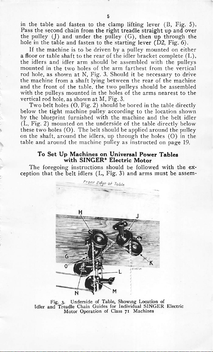
in the table and fasten to the clamp lifting lever (B, Fig. 5).
Pass the second chain from the
the
pulley
(J)
and
under
hole in the table and fasten to the
If
the
machineistobedriven
a floorortable
the
idlers
mounted
rod
hole, as
the
machine from a
and
the
frontofthe
with
the
vertical
below
by
Two
the
rod
belt
the
blueprint
(L, Fig. 2)
these
two
on
the
shaft,
table
and
To
The
foregoing
ception
that
shafttothe
and
idler
in
the
two
shownatN,
shaft
pulleys
mountedinthe
hole, as
holes (O,
tight
machine
furnished
shownatM,
mountedonthe
holes
(O).
around
around
Set
the
Up
with
Machines
instructions
the
belt
arm
holes
table,
Fig.2)shouldbeboredinthe
The
the
machine pulley as
SINGER*
idlers
right
treadle
the
pulley
rear
of the idler
(G),
starting
by a
pulley
then
lever (D2,
bracket
should be assembled
of
the
arm
farthest
Fig.3.Should
lying
between
the
two
holes of
Fig.
pulley
accordingtothe
with
the
underside of
belt
should he applied
idlers, up
it be
the
pulleys should be assembled
the
3.
machine
the
through
instructedonpage
on
Universal
Electric
Power
Motor
should be followed
(L,
Fig.
3")
and
arms
straight
up
mounted
complete
with
from
necessary
rearofthe
arms
nearesttothe
table
location
and
the
table
directly
around
the
holes
Tables
with
must
up and over
through
Fig.
on
the
6).
either
(L),
the
pulleys
the
vertical
to
drive
machine
directly
shown
belt
idler
below
the
pulley
(O)inthe
19.
the
ex
be
assem-
hiedasillustrated
the
Fig.
on
pulley of
3) in
page
19.
the
motor,
table
in
Fig.3.The
around
and
around
the
belt
idlers, up
the
machine
shouldbeapplied
through
the
pulleyasinstructed
around
holes (O,
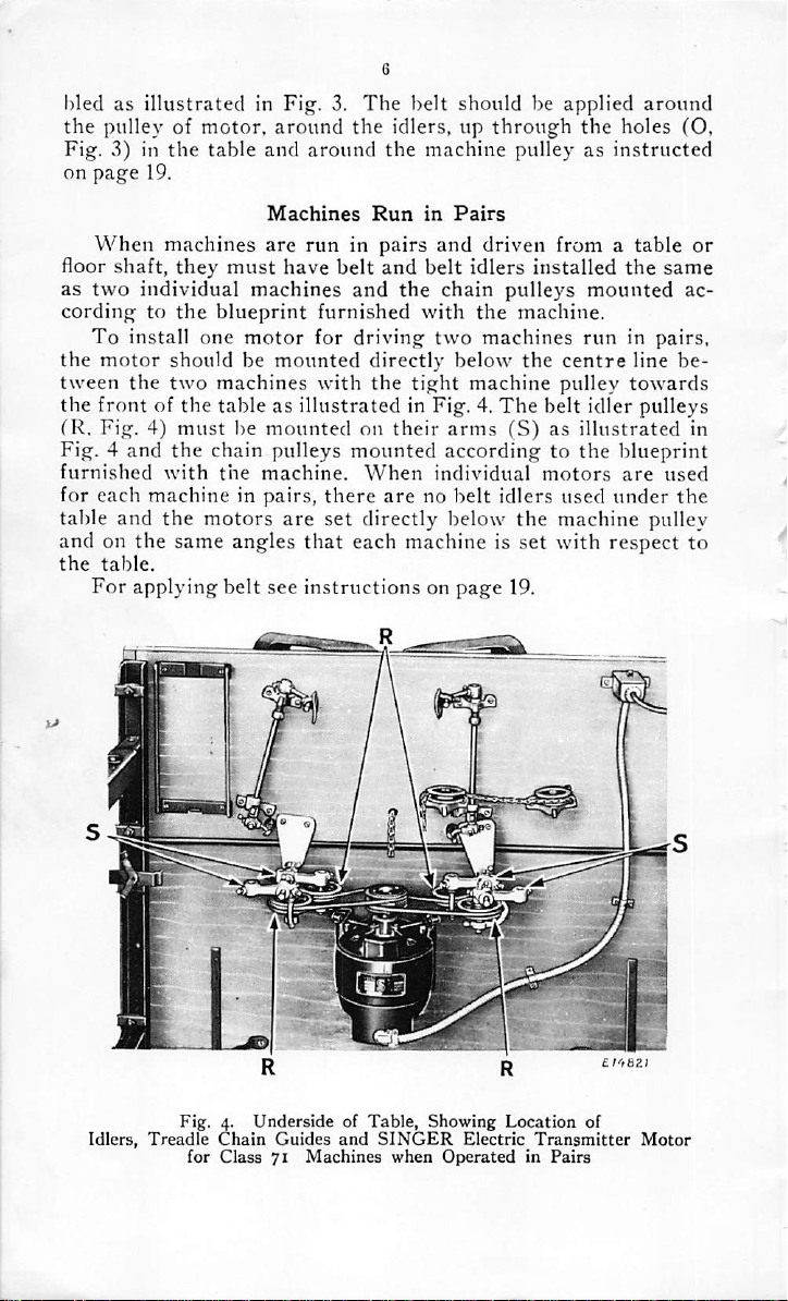
When
floor
as
two
cordingtothe
To
the
tween
the
frontofthe
fR.
Fig. 4
furnished
for
each
machines
shaft,
they
must
individual machines
blueprint
install
motor
the
one
motor
shouldbemounted
two
machines
tableasillustrated
Fig.4)must
and
with
be
the
chain pulleys
the
machineinpairs,
table and the motors
andonthe
the
table.
For
same angles
applying
belt
Machines
are
have
mounted
machine.
are
that
see
instructionsonpage
Run
in
Pairs
runinpairs
belt
and
furnished
for
driving
directly
with
the
on
mounted
When
there
and
and
belt
the
chain pulleys
with
two
below
tight
in Fig. 4.
their
arms
according to
individual
arenobelt
driven from a
idlers
installed
the
machine.
machines
the
machine
pulley
The
belt idler pulleys
(S)asillustrated
motors
idlers
used
set directly below the machine pulley
each machine is set
with
19.
table
the
mounted
runinpairs,
centre
the
line
towards
blueprint
are
under
respect
or
same
ac
be
in
used
the
to
Idlers,
Fig.4.UndersideofTable,
Treadle
for
Chain
Class
Guides
71
Machines
and
Showing
SINGER
when
OperatedinPairs
Location
Electric
of
Transmitter
Motor

To
Oil
the
Machine
Use
'TYPE
Machine Company.
coverofthis
When
B"or'TYPE
For
description of
book.
the
machine is received from
D"
OIL,
sold by
these
the
Singer
oils, see inside
factory, it should be
Sewing
front
thoroughly cleaned and oiled. Oil should be applied at each of
Fig.
5.
Oiling
Also
Pointsatthe
Adjustments
Rightofthe
on
the
Machine
Machine
the places designated by the unmarked arrows in Figs. 5. 6. 7. 21
and
26-
When
oiled
regularlvtoensure
wearofthe
It is
the
important
feed gears
for
machine.
the
machine
parts
which
to use
and
Fig.6.Oiling
Also
is in
continuous
easy
running
areinmovable
either
of the above heavy grades of oil
and
prevent
contact.
stop motion mechanism in
Pointsinthe
Adjustments
Baseofthe
on
the
Machine
use,itshould
unnecessary
the
rearofthe
Machine
be
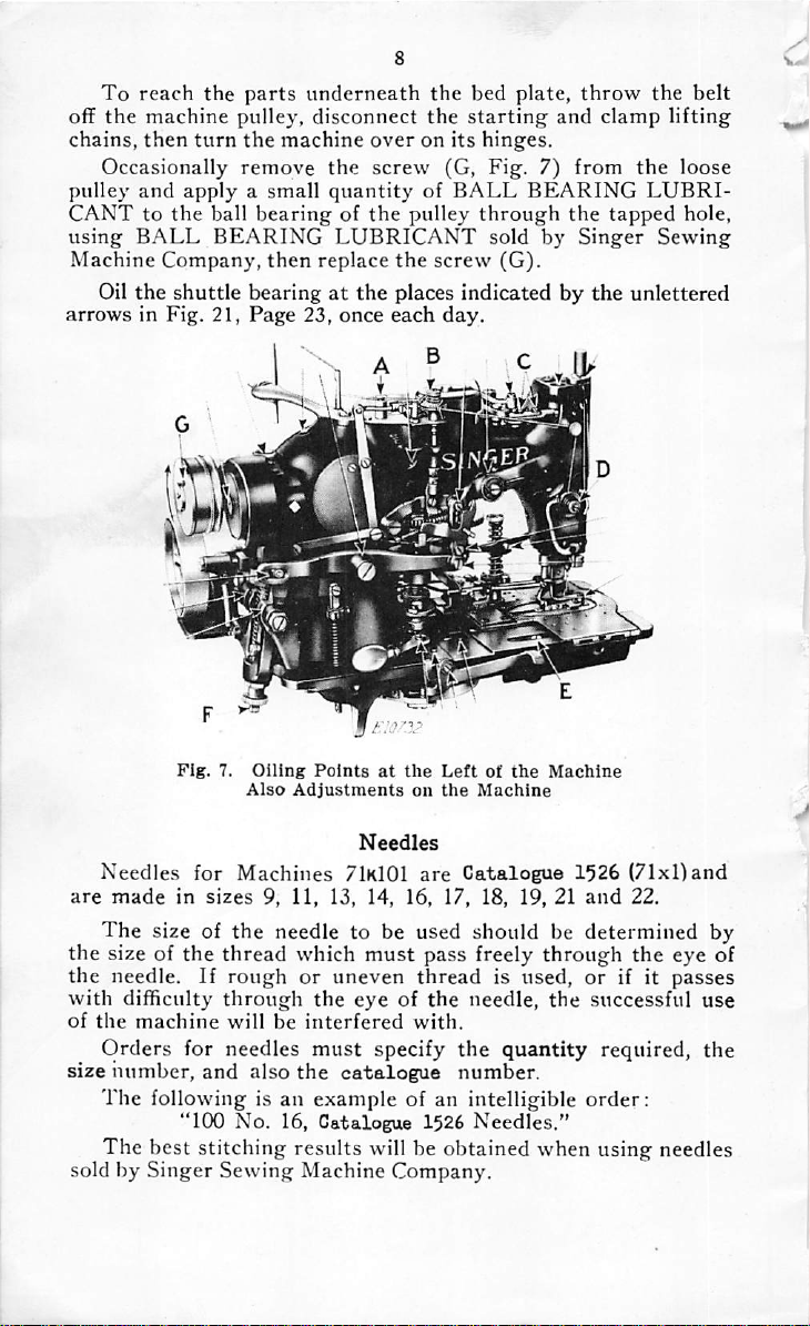
To
reach
the
off
the
machine
chains,
then
turn
Occasionally remove
pulley
CANTtothe
using
Machine
arrows
and
BALL
Oil
the
in Fig. 21,
applyasmall
ball
BEARING
Company,
shuttle
parts
underneath
pulley,
the
disconnect
machine
the
quantity
bearingofthe
LUBRICANT
then
replace
bearingatthe
Page
23,
once
the
bed plate,
the
starting
overonits
screw
pulley
hinges.
(G, Fig. 7) from
of
BALL
through
sold by
the
screw
(G).
places indicated by
each
day.
throw
and
clamp
BEARING
the
tapped
Singer
the
the
belt
lifting
the
loose
LUBRI
hole,
Sewing
unlettered
Fig.
7.
Oiling
Points
at
the
are
Needles
made
The
size of
in
for
sizes
Also
Adjustments
Needles
Machines
9, 11, 13, 14, 16, 17, 18, 19, 21
the
needle to be used should be
71k101
Leftofthe
on
the
are
Machine
Catalogue
Machine
1526
and
determined
(71xl)and
22.
by
the size of the thread which must pass freely through the eye of
the
with
of
size
the
Orders
The
needle. If
difficulty
machine
number,
following is an
rough
through
will
be
for needles
and
also
'TOO
No.
or
the
interfered
must
the
example
16,
Catalogue
uneven
eye of
specify
catalogue
thread
with.
the
is used,
needle,
the
the
quantity
number.
of an intelligible
1526
Needles."
or
if it passes
successful use
required,
order:
the
The best stitching results will be obtained when using needles
sold by Singer Sewing Machine Company.
For
needle.
For
needle.
9
Thread
Purl
Stitch buttonholes, use right twist thread in the
Whip
Stitch
buttonholes,
use
left
twist
thread
in
the
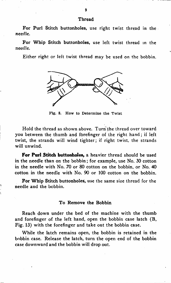
Hold
you
twist,
will
For
in
the
in
the
cotton
For
needle
Either
between
the
unwind.
Purl
needle
needle
in
Whip
and
rightorleft
Fig.
the
threadasshown
the
thumb
strands
Stitch
thanonthe
with
the
needle
Stitch
the
bobbin.
twist
8.
How
and
will wind
thread
to
above.
forefinger of
tighter;ifright
maybeusedonthe
Determine
Turn
buttonholes,aheavier
bobbin;
No.70or80cotton
with
No.
buttonholes,
90
for
or
use
example,
100
the
the
on
same
Twist
.the
the
thread
the
cotton
thread
right
over
hand;
twist, the
shouldbeused
use
No. 30
bobbin,
on
the
size
thread
bobbin.
toward
strands
or
bobbin.
for
if left
cotton
No.
40
the
Reach
and
Fig.
While
bobbin
case
down
forefingerofthe
13)
with
the
case.
downward
under
the
forefinger
latch
Release
and
To
Remove
the
left
remains
the
the
bobbin
bed
hand,
and
open,
latch,
of
turn
will
the
open
take
drop
Bobbin
the
machine
the
out
the
the
bobbinisretainedinthe
the
open
bobbin
bobbin
endofthe
with
case
case.
out.
the
latch
thumb
(B,
bobbin

To
Wind
10
the
Bobbin
Place
the
bobbin on
the
bobbin winder spindle
and
push it
up closeagainst the shoulder, having the small pin in the spindle
enter
the
slotinthe
bobbin.
£0375
Fig.
9.
Pass
(1,
Fig.9)on
Winding
the thread from the unwinder, through the thread guide
the
bobbin
winder
the
Bobbin
tension
bracket
attachedtothe
top of the machine, under between the tension discs (2, Fig. 9),
through
the
thread
guide
(3, Fig.
9),
wind
the
end of
the
thread
around the bobbin (4, Fig. 9) a few times, then push the bobbin
winder pulley against the moving belt.
When
sufficient thread
has been wound upon the bobbin, the bobbin winder will stop
autom^^'Ully.
Bobbins
can
be
wound
while
the
machine
stitching;
, -v
is
 Loading...