


D310 Series
USER MANUAL/About This Machine
Before using this Product, please read the
USER MANUAL carefully and keep it for
your reference.

Table of contents
1 Checking the Name and Function of each Part in this Machine
Front....................................................................................................................................................1-2
Side/rear..............................................................................................................................................1-3
Inside...................................................................................................................................................1-4
2 Checking the Status of This Machine Using LED Indicators
2.1 Warning Indicator............................................................................................................................ 2-2
2.2 Data Indicator.................................................................................................................................. 2-3
3 Checking the Name and Function of Each Optional Component
3.1 Checking the list of optional components.................................................................................... 3-2
List of optional components ...............................................................................................................3-2
List of other optional components......................................................................................................3-4
Front....................................................................................................................................................3-6
Side/rear..............................................................................................................................................3-8
3.2 Finisher FS-533, Punch Kit PK-519 ............................................................................................... 3-9
3.3 Job Separator JS-506................................................................................................................... 3-10
3.4 Finisher FS-534/Saddle Stitcher SD-511/Punch Kit PK-520 ..................................................... 3-11
4 Checking the Specifications of This Machine
Main Unit.............................................................................................................................................4-2
Scanning Function Specifications ......................................................................................................4-3
Printer Specifications..........................................................................................................................4-4
5 Checking the Specifications of Optional Components
Fax Kit FK-513 ....................................................................................................................................5-2
Reverse Automatic Document Feeder DF-628...................................................................................5-2
Paper Feed Cabinet PC-114...............................................................................................................5-3
Paper Feed Cabinet PC-214...............................................................................................................5-3
Paper Feed Cabinet PC-414...............................................................................................................5-4
Finisher FS-534...................................................................................................................................5-4
Saddle Stitcher SD-511 ......................................................................................................................5-6
Punch Kit PK-520 ...............................................................................................................................5-6
Finisher FS-533...................................................................................................................................5-6
Punch Kit PK-519 ...............................................................................................................................5-7
Job Separator JS-506.........................................................................................................................5-8
Authentication Unit AU-102 ................................................................................................................5-8
Authentication Unit AU-201S..............................................................................................................5-9
Upgrade Kit UK-212 .........................................................................................................................5-10
6 Using the Authentication Unit (Biometric Type)
6.1 Authentication Unit (Biometric Type)............................................................................................ 6-2
6.2 Status of Authentication Unit......................................................................................................... 6-3
6.3 Operations Required to Use This Function (for the Administrator) ........................................... 6-4
6.3.1 Configuring Authentication Settings of This Machine.........................................................................6-4
6.3.2 Registering User Authentication Information ......................................................................................6-5
6.4 Logging in to This Machine............................................................................................................ 6-8
6.5 Using Data Administrator (for the Administrator)........................................................................ 6-9
6.5.1 Data Administrator ..............................................................................................................................6-9
6.5.2 Setting Up the Operating Environment...............................................................................................6-9
[About This Machine] 1-1

Installing BioDriver (USB-Driver) (Windows 7/8.1/10).........................................................................6-9
Installing BioDriver (USB-Driver) (Windows Vista) ............................................................................6-11
Installing
Data Administrator PlugIn for Biometric Authentication Unit AU-102 ..............................................6-12
6.5.3 Registering User Authentication Information ....................................................................................6-13
7Using the Authentication Unit (IC Card Type)
7.1 Authentication Unit (IC card type) ................................................................................................. 7-2
7.2 Status of authentication unit.......................................................................................................... 7-3
7.3 Operations Required to Use This Function (for the Administrator) ........................................... 7-4
7.3.1 Configuring Authentication Settings of This Machine.........................................................................7-4
7.3.2 Registering User Authentication Information ......................................................................................7-6
7.4 Logging in to This Machine............................................................................................................ 7-7
7.5 Using Data Administrator (for the Administrator)........................................................................ 7-8
7.5.1 Data Administrator..............................................................................................................................7-8
7.5.2 Setting up the Operating Environment ...............................................................................................7-8
Installing IC CardDriver (USB-Driver) (Windows 7/8.1/10)..................................................................7-8
Installing IC CardDriver (USB-Driver) (Windows Vista) .....................................................................7-10
Installing Data Administrator PlugIn for IC Card Authentication Unit
AU-201S............................................................................................................................................7-11
7.5.3 Registering user Authentication Information.....................................................................................7-12
[About This Machine] 1-2

1
Checking the Name and
Function of each Part in this
Machine
1 Checking the Name and Function of each Part in
1
1 Checking the Name and Function of each Part in
this Machine
Front
1
2
3
4
6
5
7
10
13
11
8
9
12
this Machine
Front
1
10
9
8
11
12
13
1
2
3
4
5
6
7
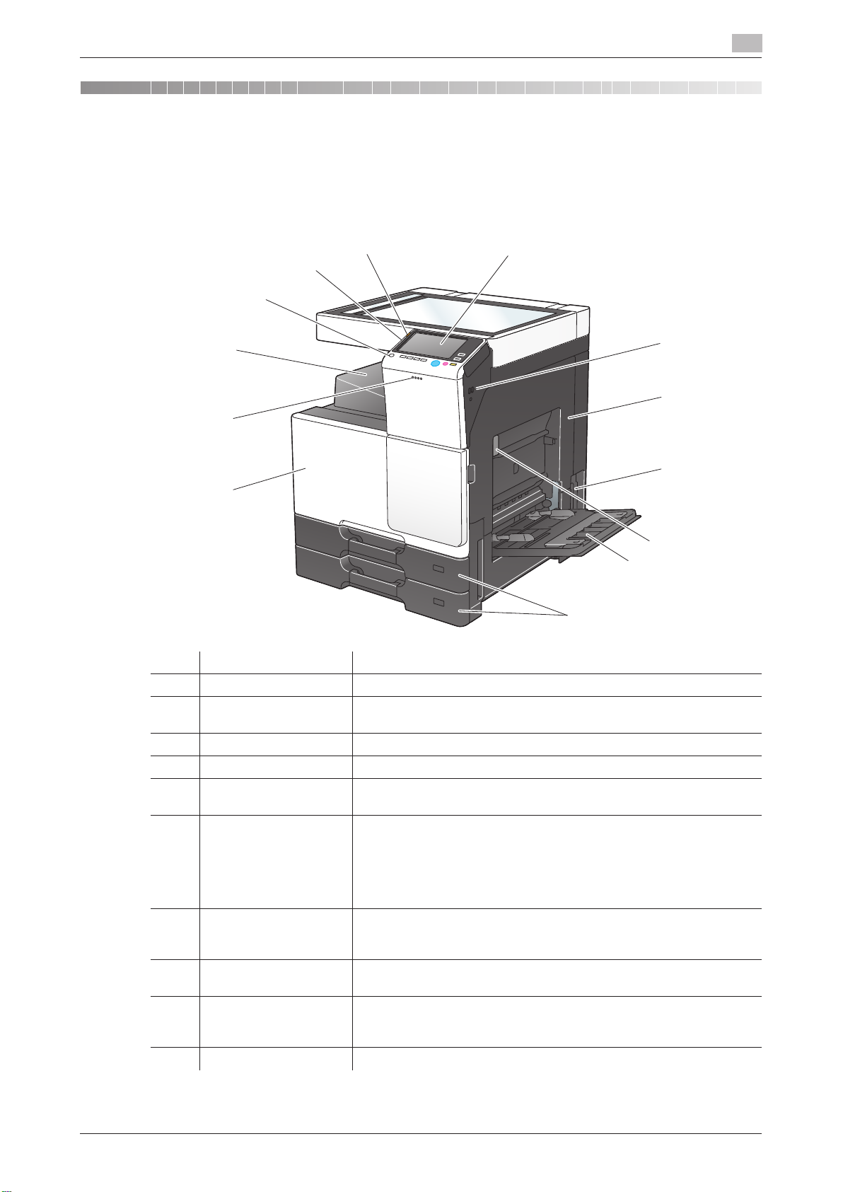
No. Name Description
1 Control Panel Used to configure various settings in this machine.
2 USB Port (Type A)
USB2.0/1.1
3 Right Door Open this door to clear a paper jam.
4 Main Power Switch Press this switch to turn the machine on or off.
5 Right Door Release
Lever
6 Bypass Tray Used to print data on irregularly size paper, thick paper, transparen-
7 Tray1, Tray2 Allows you to load up to 500 sheets.
8 Front Door Open this door to replace the Toner Cartridge, Waste Toner Box, or
9 Data Indicator Flashes or lights up to indicate the data receiving status on this ma-
10 Output Tray Outputs printed pages.
Used to connect an external memory unit (USB memory unit) to this
machine.
Used to lock the Right Door.
cies, postcards (4 e 6 (A6 Card)), envelopes, or label sheets.
The Bypass Tray can hold up to 100 sheets of plain paper, 20 sheets
of Thick 1, 20 sheets of Thick 1+, 20 sheets of Thick 2, 20 sheets of
Thick 3, 20 transparencies, 10 envelopes, 20 postcards (4 e 6 (A6
Card)), label sheets, or index paper, and 1 banner paper of sheet.
These trays can hold up to 150 sheets respectively of Thick 1, Thick
1+, Thick 2, and Thick 3.
Drum Unit.
chine.
For details, refer to page 2-3.
[About This Machine] 1-2
No. Name Description
3
2
1
11 Power key Press this key to switch to the Power Save mode.
During the normal operation, the key lights up blue. During the power
save mode, the key flashes blue or lights up orange.
12 Stylus Pen Used to select a menu on the Touch Panel, or enter characters.
13 Warning Indicator Flashes or lights up to indicate that a problem has occurred in this ma-
chine.
For details, refer to page 2-2.
Side/rear
1
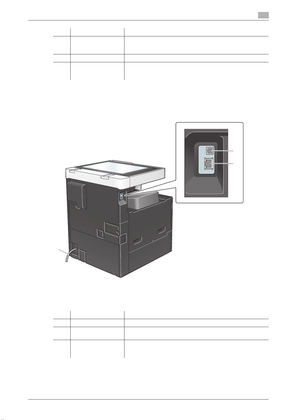
No. Name Description
1 Power Cord Used to supply power to this machine.
2 USB Port (Type B)
USB2.0/1.1
3 Network Connector
(10Base-T/100BaseTX/1000Base-T)
Connect to this port when using this machine as a USB-connected
printer.
Connect to this port when using this machine as a network printer or
network scanner.
[About This Machine] 1-3
Inside
1
Inside
1
3
2
4
5
6
8
7
9
11
12
10
1
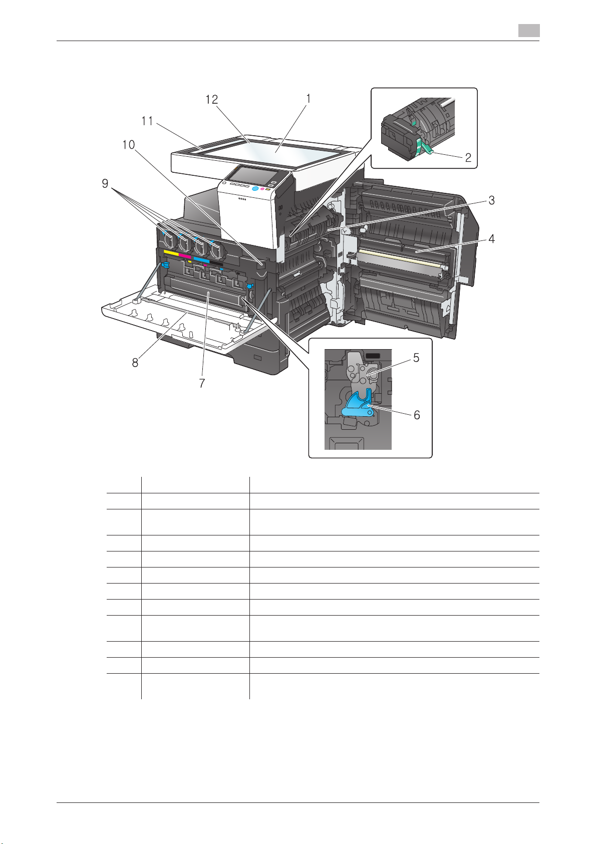
No. Name Description
1 Original Glass Used to load the original.
2 Fusing Adjustment
Lever
3 Fusing Unit Used to fuse toner to paper using heat and pressure.
4 Transfer Unit Used to transcribe toner onto paper.
5 Drum Unit Used to create a print image.
6 Lock Release Tab Used to remove the Drum Unit. (Black only)
7 Waste Toner Box Used to collect used waste toners.
8 Printhead Cleaner Used to clean the surface of the Print Head Glass when the Drum
9 Toner Cartridge Contains toner, with which a print image is created.
10 Slit Scan Glass Used to scan an original image when using the ADF.
11 Original Scale Load the original along this scale. This scale is also used to check the
Used to clear paper jams in the fusing unit when printing envelopes.
Unit is being replaced.
size of the loaded original.
[About This Machine] 1-4

2
Checking the Status of This
Machine Using LED
Indicators
2.1 Warning Indicator
2
2 Checking the Status of This Machine Using LED In-
dicators
2.1 Warning Indicator
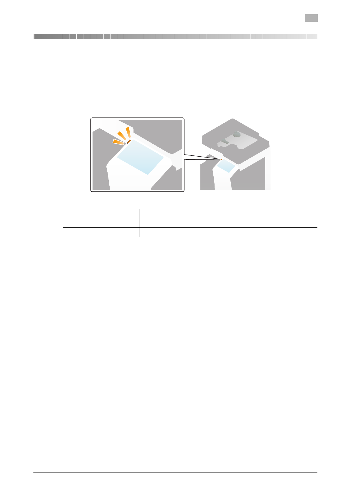
Flashes or lights up to indicate that a problem has occurred in this machine.
Status of LED Status of this machine
Flash: Orange Indicates that a warning has occurred in this machine.
Light up: Orange Indicates that this machine is stopped due to an error.
[About This Machine] 2-2

2.2 Data Indicator
2.2 Data Indicator
Flashes or lights up to indicate the data receiving status on this machine.
Status of LED Status of this machine
Flash: Blue Indicates that print data is currently being received.
Light up: Blue Indicates that data is currently being stored.
2
[About This Machine] 2-3

2.2 Data Indicator
2
[About This Machine] 2-4

3
Checking the Name and
Function of Each Optional
Component
3.1 Checking the list of optional components
3.1 Checking the list of optional components
3
3 Checking the Name and Function of Each Optional
Component
3.1 Checking the list of optional components
List of optional components
1
32
4
20
17
16
22
23
1415 12
24
18 19
21
13
78
9
10
5
6
11
3 Checking the Name and Function of Each Optional
Component
3.1 Checking the list of optional components
List of optional components
3
[About This Machine] 3-2

3.1 Checking the list of optional components
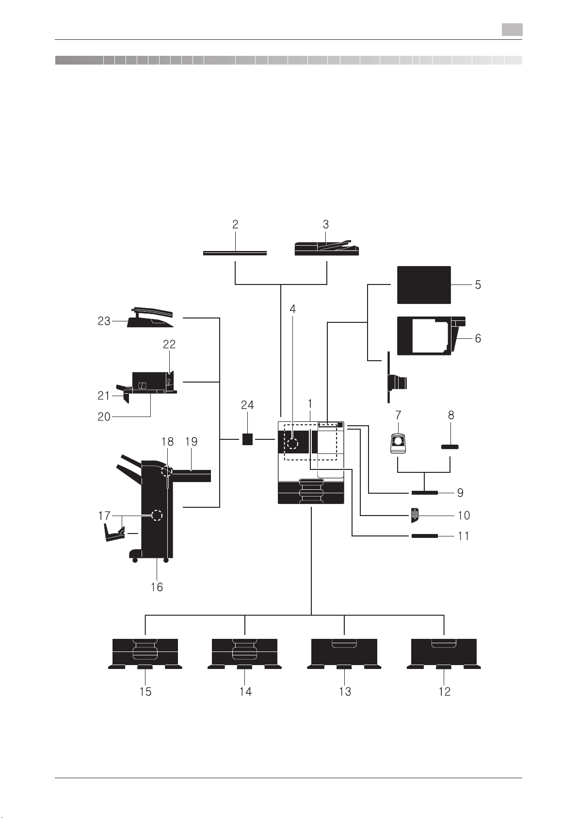
No. Name Description
1 Main unit Scans the original in the scanner section, and prints a scanned image
2 Original Cover OC-
514
3 Reverse Automatic
Document Feeder DF628
4 FAX Kit FK-513 Used to operate this machine as a fax machine.
5 Clean Unit CU-101 Collects small particles (UFP) generated in this machine to prevent
6 Mount Kit MK-748 This unit is required to install Clean Unit CU-101.
7 Authentication Unit
AU-102
8 Authentication Unit
AU-201S
9 Working Table WT-
506
10 Keypad KP-101 It is equipped on the side of the Control Panel.
11 Keyboard Holder KH-
102
12 Desk DK-514 Used to install this machine on the floor.
13 Paper Feed Cabinet
PC-414
14 Paper Feed Cabinet
PC-214
15 Paper Feed Cabinet
PC-114
16 Finisher FS-534 Sorts, groups and staples printed paper before outputting it.
17 Saddle Stitcher SD-
511
18 Punch Kit PK-520 Install this unit onto Finisher FS-534.
19 Relay Unit RU-514 This unit is required to install Finisher FS-534.
in the printer section.
This unit is referred to as "machine", "main unit", or "C287/C227" in
the manual.
Used to fix the loaded originals.
This is referred to as Original Cover in the manual.
Automatically feeds and scans originals by page. This unit also reverses and automatically scans 2-sided originals.
This unit is referred to as ADF in the manual.
The Hard Disk is optional in some areas. When you use this machine
as a fax machine, the optional Hard Disk must also be installed in this
machine.
them from escaping this machine.
The Mount Kit MK-748 is required to install Clean Unit CU-101.
Performs user authentication by scanning vein patterns in the finger.
To install the Authentication Unit AU-102, the Local Interface Kit
EK-608 or Local Interface Kit EK-609 is required in addition to the
Working Table WT-506.
This unit is referred to as an Authentication Unit in the manual.
Performs user authentication by scanning information recorded on
the IC card or NFC-compatible Android terminal.
To install the Authentication Unit AU-201S, the Local Interface Kit
EK-608 or Local Interface Kit EK-609 is required in addition to the
Mount Kit MK-735.
This unit can also be installed on the Working Table WT-506.
This unit is referred to as an Authentication Unit in the manual.
Provides an area to temporarily place an original or other materials.
This is also used when the Authentication Unit AU-102 or Authenti-
cation Unit AU-201S is installed.
Allows you to enter numbers by using the Hardware Keypad.
Install this holder to use a external keyboard.
For details on external keyboards, contact your service representative.
This unit is referred to as Desk in the manual.
Allows you to load up to 2500 sheets of 8-1/2 e 11 (A4) size.
This unit is referred to as LCT (built-in) in the manual.
Allows you to load up to 500 sheets respectively in the top and bottom
trays.
This unit is referred to as Double Paper Feed Cabinet in the manual.
Allows you to load up to 500 sheets in the top tray and use the bottom
tray as a storage box.
This unit is referred to as Single Paper Feed Cabinet in the manual.
To install the Finisher FS-534, the Relay Unit RU-514 and Mount Kit
MK-603 are required. Also, Desk DK-514, Paper Feed Cabinet PC414, Paper Feed Cabinet PC-114, or Paper Feed Cabinet PC-214
must be installed on this machine.
Install this unit onto Finisher FS-534. This unit supports the
fold/center staple function.
It is referred to as Saddle Stitcher in the manual.
This unit supports the punching function.
3
"D311/D310" in
[About This Machine] 3-3

3.1 Checking the list of optional components
No. Name Description
20 Finisher FS-533 Install this unit onto the output tray of this machine.
The Mount Kit MK-602 and Mount Kit MK-603 are required to install
Finisher FS-533.
Sorts, groups and staples printed paper before outputting it.
21 Mount Kit MK-602 This unit is required to install Finisher FS-533.
22 Punch Kit PK-519 Install this unit onto Finisher FS-533.
23 Job Separator JS-506 Install this unit onto the output tray of this machine.
24 Mount Kit MK-603 This unit is required when the Finisher FS-534, Finisher FS-533, or
This unit supports the punching function.
This unit sorts printed sheets.
The Mount Kit MK-603 is required to install Job Separator JS-506.
This unit is referred to as Job Separator in the manual.
Job Separator JS-506 is installed on this machine.
List of other optional components
The following options are built into this machine and are not shown in the figure.
No. Name Description
1 Stamp Unit SP-501 Stamps a scanned original when sending a fax. This unit allows you
to check that the original has been scanned.
2 Spare TX Marker
Stamp 2
3 Local Interface Kit
EK-608
4 Local Interface Kit
EK-609
5 i-Option LK-102 v3 Supports the PDF processing function that is one of the advanced
6 i-Option LK-104 v3 Supports the voice guidance function that is one of the advanced
7 i-Option LK-105 v4 Supports the searchable PDF function that is one of the advanced
8 i-Option LK-106 Used to add a bar code font that is one of special fonts.
9 i-Option LK-107 Used to add a unicode font that is one of special fonts.
10 i-Option LK-108 Used to add an OCR font that is one of special fonts.
11 i-Option LK-110 v2 Used to add an advanced function that converts a file into the DOCX
A replacement stamp for the Stamp Unit SP-501.
Install this unit when using the voice guidance function, Authentica-
tion Unit AU-102, Authentication Unit AU-201S, or Upgrade Kit
UK-212.
The speaker and USB port are added.
This unit is referred to as the Local Interface Kit in the manual.
Install this unit when using the voice guidance function, Authentica-
tion Unit AU-102, Authentication Unit AU-201S, Upgrade Kit UK212, or the connection function with a Bluetooth LE-compatible iOS
terminal.
The speaker, USB port, and receiving device for Bluetooth LE communication are added.
This unit is referred to as Local Interface Kit or Local Interface Kit
(voice guidance / Bluetooth LE compatible).
• For details on the association with an iOS terminal, refer to "User's
• For details on user authentication of an iOS terminal, refer to "Us-
functions.
functions.
functions.
In the standard, the OCR-B font (PostScript) is available. Installing the
i-Option LK-108 allows use of the OCR-A font (PCL).
or XLSX type or generates highly-functional and high-quality data.
i-Option LK-110 v2 includes the function licenses for i-Option LK102 v3 and LK-105 v4. If you purchase i-Option LK-110 v2, you do
not need to purchase i-Option LK-102 v3 or
For details about functions able to be added, refer to "User's
Guide[Advanced Function Operations]/[Advanced Functions]".
3
Guide[Web Management Tool]/[Associating with External Application]".
er's Guide[Web Management Tool]/[Restricting Users from Using
this Device]".
LK-105 v4.
[About This Machine] 3-4

3.1 Checking the list of optional components
No. Name Description
12 i-Option LK-111 Supports the ThinPrint function that is one of the advanced functions.
13 i-Option LK-114 Supports the serverless pull printing function that is one of the ad-
vanced functions.
14 i-Option LK-115 v2 You can use TPM (Trusted Platform Module) that is one of the ad-
vanced functions. Security enhancement is realized by encrypting
confidential information such as certificates and passwords of this
machine.
15 Upgrade Kit UK-211 • Install this unit when using i-Option LK-102 v3, LK-104 v3, LK-
• Install this unit when using My Address in association with My
This unit is referred to as Extension Memory in the manual.
The Hard Disk is optional in some areas. When installing the optional
Extension Memory, the optional Hard Disk must also be installed in
this machine.
16 Upgrade Kit UK-212 Allows you to use this machine in a wireless network environment.
17 Heater HT-509 Prevents paper in a paper tray from being affected by humidity.
18 Power Supply BOX
MK-734
19 Mount Kit MK-735 Required to have
20 Hard Disk HD-522 Used to increase the hard disk storage capacity to add functions.
To install the Upgrade Kit UK-212, the Local Interface Kit EK-608
or Local Interface Kit EK-609 is required.
This unit is referred to as the Wireless LAN Interface Kit in the manual.
The Heater HT-509 can be mounted when you purchase the Paper
Feed Cabinet PC-114, Paper Feed Cabinet PC-214, Paper Feed
Cabinet PC-414, or Desk DK-514.
Turns on/off the Heater HT-509 operations.
The Power Supply BOX MK-734 can be mounted when you purchase the Paper Feed Cabinet PC-114, Paper Feed Cabinet PC-
214, Paper Feed Cabinet PC-414, or Desk DK-514.
unit.
The hard disk is installed as the standard in North America and Europe.
3
105 v4, LK-106, LK-107, LK-108, LK-110 v2, or LK-114.
Panel Manager.
Authentication Unit AU-201S built in to the main
[About This Machine] 3-5
3.1 Checking the list of optional components
3.1 Checking the list of optional components
3
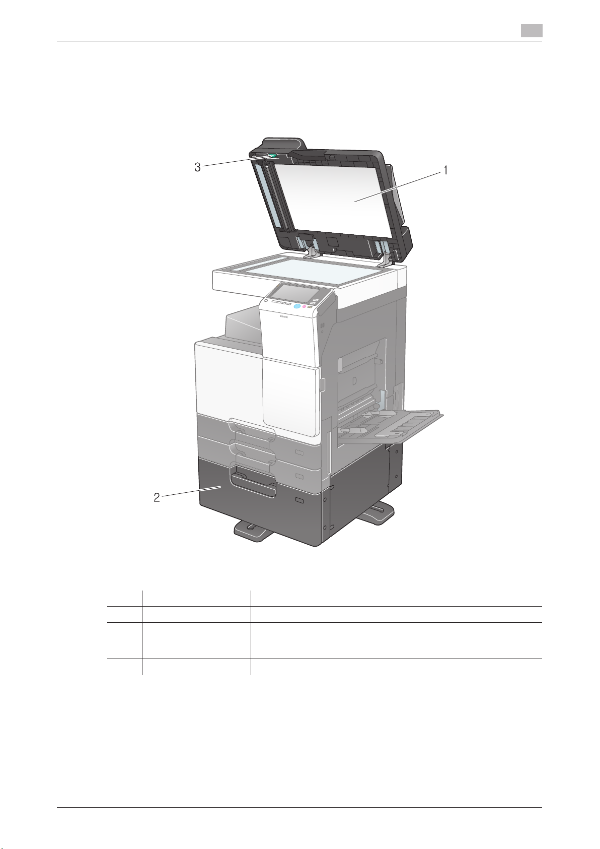
Front
The illustration shows the main unit with Reverse Automatic Document Feeder DF-628, and Paper Feed
Cabinet PC-414.
1
2
3
Front
The illustration shows the main unit with Reverse Automatic Document Feeder DF-628, and Paper Feed
Cabinet PC-414.
3
No. Name Description
1 Original Pad Fixes the loaded originals.
2 LCT (built-in) Allows you to load up to 2500 sheets.
This tray can hold up to 1000 sheets of Thick 1, Thick 1+, Thick 2, and
Thick 3.
3 Jam Removal Dial Turn this dial to remove paper that caused a paper jam in the ADF.
[About This Machine] 3-6

3.1 Checking the list of optional components
3.1 Checking the list of optional components
3
The illustration shows the main unit with Paper Feed Cabinet PC-214 or Paper Feed Cabinet PC-114, and
Reverse Automatic Document Feeder DF-628.
4
5
6
7
8
9
10
11
12
The illustration shows the main unit with Paper Feed Cabinet PC-214 or Paper Feed Cabinet PC-114, and
Reverse Automatic Document Feeder DF-628.
3
No. Name Description
4 Left Cover Release
Lever
5 Left Cover Open the Left Cover when clearing a paper jam.
6 Lateral Guide Adjust this guide along the width of the original.
7 Original Tray Load the original face up in this tray.
8 Original Output Tray The scanned original is fed out onto this tray.
9 Bottom Right Door Open this door when clearing a paper jam in the Tray3 or Tray4 trans-
10 Bottom Right Door
Release Lever
11 Tray3 Allows you to load up to 500 sheets.
12 Tray4/Storage Box Used as a Storage Box when installing Single Paper Feed Cabinet.
Used to open the Left Cover.
port unit.
Used to lock the Bottom Right Door.
This tray can hold up to 150 sheets of Thick 1, Thick 1+, Thick 2, and
Thick 3.
This box allows you to load up to 500 sheets when Double Paper
Feed Cabinet is installed.
This tray can hold up to 150 sheets of Thick 1, Thick 1+, Thick 2, and
Thick 3.
[About This Machine] 3-7
3.1 Checking the list of optional components
2
1
3
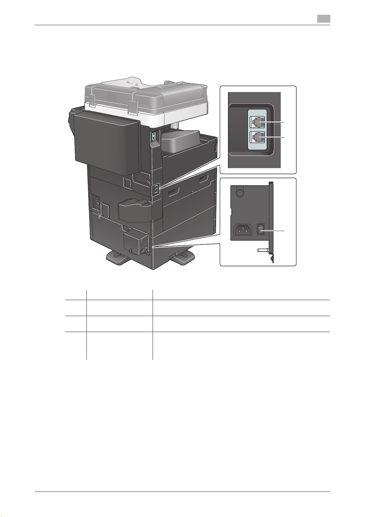
Side/rear
The illustration shows the main unit with Reverse Automatic Document Feeder DF-628, Paper Feed Cabinet PC-214, Fax Kit FK-513, Power Supply BOX MK-734, Clean Unit CU-101, and Mount Kit MK-748.
3
TEL
LINE
No. Name Description
1 Jack for connecting a
telephone (TEL PORT)
2 Telephone Jack 1
(LINE PORT)
3 Heater Power Switch Used to turn Heater operations on or off. This function prevents paper
Used to connect a telephone cord.
Used to connect a general telephone subscriber line.
from being affected by humidity when the power is turned on.
The dehumidifier Heater is available when you purchase Single/Dou-
ble Paper Feed Cabinet, LCT (built-in), or Desk.
[About This Machine] 3-8
3.2 Finisher FS-533, Punch Kit PK-519
3.2 Finisher FS-533, Punch Kit PK-519
3
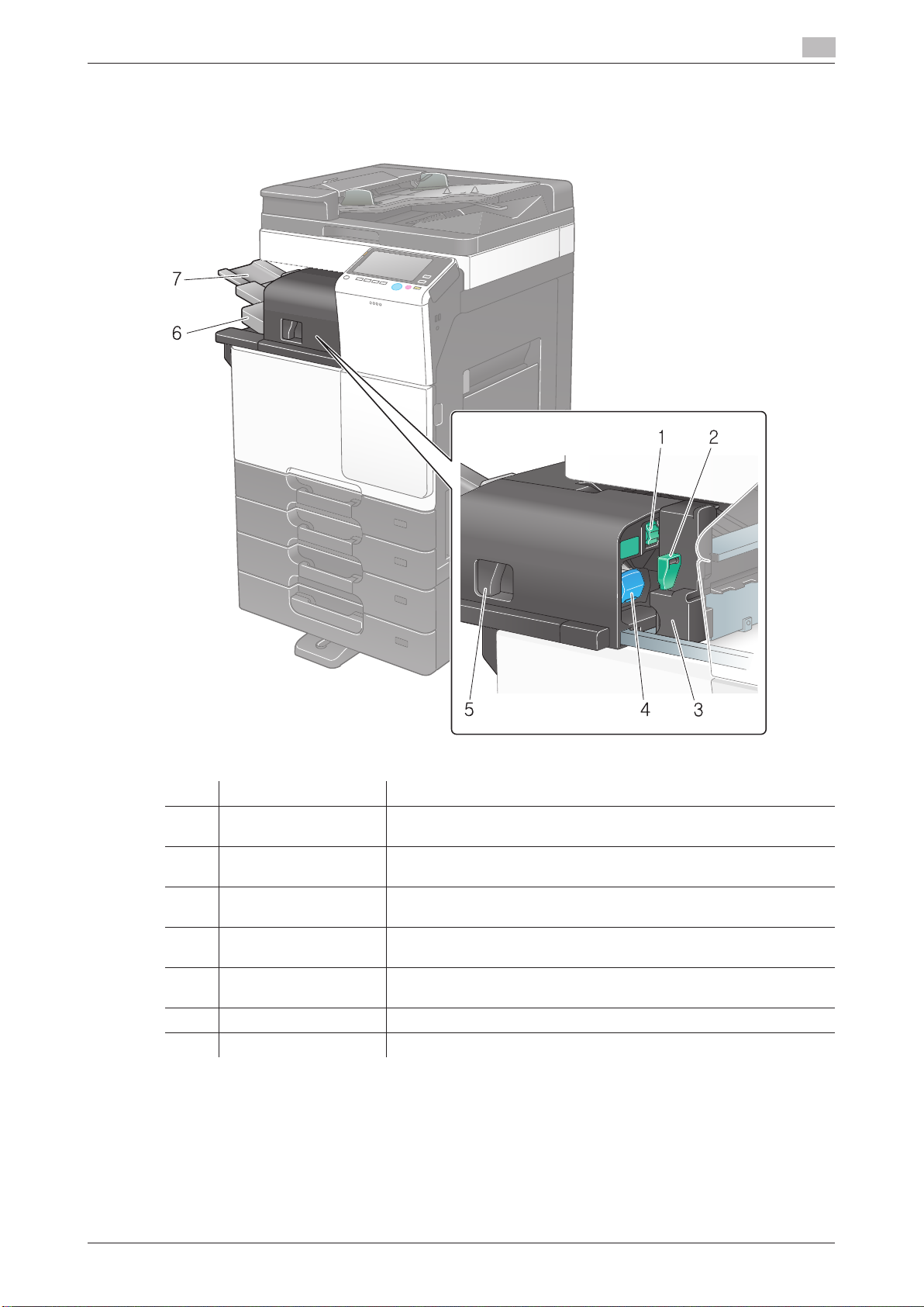
3.2 Finisher FS-533, Punch Kit PK-519
1 2
3
45
7
6
3.2 Finisher FS-533, Punch Kit PK-519
3
No. Name Description
1 Jam Removal Dial
2 Punch Kit Release Le-
3 Punch Kit You can punch printed sheets for filing by installing the Punch Kit in
4 Staple Cartridge Pull out this cartridge from the finisher when clearing a staple jam or
5 Lock Release Lever Used to release and move the finisher and main unit when clearing a
6 Output Tray Outputs printed pages.
7 Tray Extension Pull this tray out when handling paper longer than 8-1/2 e 11 (A4) w.
[FS1]
ver [FS2]
Turn this dial to remove paper that caused a paper jam in the finisher.
Used to open the punch kit when removing a punch scrap box.
the finisher.
replacing a staple cartridge.
paper jam.
[About This Machine] 3-9

3.3 Job Separator JS-506
3.3 Job Separator JS-506
3
3.3 Job Separator JS-506
1
2
3.3 Job Separator JS-506
3
No. Name Description
1 Output Tray1 Outputs printed pages.
2 Output Tray2 Outputs printed pages.
[About This Machine] 3-10
 Loading...