

Page 1

Series
USER MANUAL
Read the User Manual before operating the
product, and keep the manual at a convenient
place near the product.
3dprinter.sindoh.com
Page 2

Safety Instructions
Be sure to observe the followIng instructions when using the device.
Warning:
Directly plug the power cord in the receptacle on the wall. Do not use extension cord.
If the power cable or plug is worn or damaged, pull out the power plug.
The exposure of the interior of the machine can cause electric shock or burns.
Do not remove covers or screws other than specified in this manual.
Please be cautious. In the process of printing, the temperature of the nozzle and the heated
bed rise higher than 100 degrees Celsius.
Do not place the machine in a highly moist environment as it may cause deformation and
malfunction.
Avoid contact of electrical terminal with metal product such as necklaces, coins, keys,
watches, etc.
Do not hold the shaft for lifting or moving of the printer.
For the following situations turn off power and pull out the power plug
-
When in contact with liquid
-
When in need for a service or repair request
-
When the device cover is damaged
For the method of disposal contact local service center or use a proper collection site.
Please turn off power when leaving the office after business hours or in circumstances where
machine is unoccupied for a long period of time as it may cause abrupt fire accidents.
Failure to observe the instructions may lead to death or serious injury.
Caution:
Protect device from humid or wet conditions eg. rain, snow, etc
Remove power cord from receptacle on the wall before moving device.
Be careful not to damage power cord while device is being translocated.
When removing the power cord, please pull the plug and not the power cable.
Be cautious of clips, staples and any other small metal objects from falling inside the device.
Please be cautious on safety when touching the interior of the machine, e.g. cleaning the
interior.
Do not dispose of device or consumables together with household waste.
For the method of disposal, please contact local service center or use a proper collection site.
Interior of device may be very hot. Please do not touch the part with “Caution: High
Temperature” sign or its surrounding areas as it may cause burns.
Our product maintains high quality standards and performance.
It is recommended to use genuine components only, components can be acquired from any
authorized distributors.
Failure to observe instructions may cause injuries or damages to property.
Page 3

Before use
Thank you for purchasing our product.
This user manual contains detailed information about correct use of device and easy
maintenance to maintain the optimal state, and to contribute to the rationalization of office
work of your company.
Carefully read the user manual before using the device and keep close at hand.
In order to use device correctly and safely, please carefully note the precautions before use.
Prohibition and limitation
1. This User Manual has been created for the convenience of the user, actual product
may differ from image and explanations shown.
2. The contents of this user manual is subject to change without notice. We are not
responsible for the direct and/or indirect loss or damages caused by results of handling
or operating the product in any case and for results occurring from user’s negligence.
3. The copyrighted literary works can be duplicated and used for personal use or
household use and within the same parameter. In other cases than the
aforementioned, it is prohibited by law.
4. The above details present only a part of the applicable laws and regulations.
Details on these laws/regulations may not be stated as they are. We do not guarantee
its correctness and completeness. Please consult a legal advisor to check if the object
you intend to print is legal.
5. User is responsible for all loss derived from modification of the product executed by
the user or third party.
6. Font used in the printer GUI and the user manual is the “NANUM” font provided by NAVER.
Page 4

Contents
Before using the Machine
1. Preface -------------------------------------------------------------------------------------------------------------------------- 1
2. Conventions ------------------------------------------------------------------------------------------------------------------ 2
Symbols ------------------------------------------------------------------------------------------------------------------------ 2
3. Safety Information ----------------------------------------------------------------------------------------------------------3
4. Precautions ------------------------------------------------------------------------------------------------------------------- 5
4.1 Installation ---------------------------------------------------------------------------------------------------------------------- 5
4.2 Moving the Machine ---------------------------------------------------------------------------------------------------------- 6
5. Consumables Handling ---------------------------------------------------------------------------------------------------7
5.1 PLA ----------------------------------------------------------------------------------------------------------------------------- 7
5.2 ABS ----------------------------------------------------------------------------------------------------------------------------- 7
5.3 Flexible -------------------------------------------------------------------------------------------------------------------------- 8
6. Instructions for Use --------------------------------------------------------------------------------------------------------9
7. Ventilation ------------------------------------------------------------------------------------------------------------------- 10
8. Notices ----------------------------------------------------------------------------------------------------------------------- 11
9. Disposal of Used Battery ---------------------------------------------------------------------------------------------- 14
10. Wifi Module Disclaimer ------------------------------------------------------------------------------------------------- 15
11. USB Memory Disclaimer ----------------------------------------------------------------------------------------------- 17
Chapter 1 Preparations for Machine Operation
1. Machine Specifications ------------------------------------------------------------------------------------------------ 1-2
1.1 Printing ----------------------------------------------------------------------------------------------------------------------- 1-2
1.2 Temperature/Speed ------------------------------------------------------------------------------------------------------ 1-2
1.3 Machine ---------------------------------------------------------------------------------------------------------------------- 1-2
1.4 Software/Support --------------------------------------------------------------------------------------------------------- 1-2
1.5 Default Setting of Print layer Width ----------------------------------------------------------------------------------- 1-2
2. Basic Components ------------------------------------------------------------------------------------------------------ 1-3
3. Understanding the Device Parts ------------------------------------------------------------------------------------ 1-4
4. Installation (Product connection, Cartridge Setup and includes Software Installation) -------- 1-6
4.1 Device Connection -------------------------------------------------------------------------------------------------------- 1-6
4.2 Program Installation ------------------------------------------------------------------------------------------------------ 1-6
ⅰ
Page 5

Chapter 2 UI Menu Functions
1. UI Menu Function description ---------------------------------------------------------------------------------------- 2-2
1.1 CARTRIDGE ---------------------------------------------------------------------------------------------------------------- 2-3
LOAD ------------------------------------------------------------------------------------------------------------------------- 2-3
UNLOAD -------------------------------------------------------------------------------------------------------------------- 2-5
UNLOCK -------------------------------------------------------------------------------------------------------------------2-10
1.2 Settings -------------------------------------------------------------------------------------------------------------------2-13
X, Y, Z -----------------------------------------------------------------------------------------------------------------------2-14
EXTRUDER ---------------------------------------------------------------------------------------------------------------2-15
BED LEVELING ----------------------------------------------------------------------------------------------------------2-17
Z OFFSET -----------------------------------------------------------------------------------------------------------------2-20
NOZZLE CLEANING ----------------------------------------------------------------------------------------------------2-22
CLEANING CASE -------------------------------------------------------------------------------------------------------2-23
NETWORK -----------------------------------------------------------------------------------------------------------------2-25
BED LOWERING ---------------------------------------------------------------------------------------------------------2-28
TEST PRINT --------------------------------------------------------------------------------------------------------------2-29
ACTIVE LEVELING ------------------------------------------------------------------------------------------------------2-31
SECURITY -----------------------------------------------------------------------------------------------------------------2-32
VOICE GUIDE ------------------------------------------------------------------------------------------------------------2-34
BEEP SOUND ------------------------------------------------------------------------------------------------------------2-35
LANGUAGE ---------------------------------------------------------------------------------------------------------------2-37
E-MAIL ----------------------------------------------------------------------------------------------------------------------2-38
UNIT ------------------------------------------------------------------------------------------------------------------------2-42
TIME SETTING -----------------------------------------------------------------------------------------------------------2-44
TIME ZONE ---------------------------------------------------------------------------------------------------------------2-45
POWER SAVING MODE ----------------------------------------------------------------------------------------------2-47
LAMP ------------------------------------------------------------------------------------------------------------------------2-48
WEB ------------------------------------------------------------------------------------------------------------------------2-50
S/W UPDATE -------------------------------------------------------------------------------------------------------------2-51
NOZZLE REPLACEMENT ----------------------------------------------------------------------------------------------2-53
CLOUD ---------------------------------------------------------------------------------------------------------------------2-55
OPEN MATERIAL --------------------------------------------------------------------------------------------------------2-56
1.3 Information -----------------------------------------------------------------------------------------------------------------2-60
ⅱ
Page 6

Chapter 3 Printing
1. Printing ---------------------------------------------------------------------------------------------------------------------- 3-2
1.1 Printing from USB Flash Drive ----------------------------------------------------------------------------------------- 3-2
1.2 Printing Via PC ------------------------------------------------------------------------------------------------------------- 3-8
1.3 Print Job Management -------------------------------------------------------------------------------------------------- 3-8
1.4 Changing Filaments ----------------------------------------------------------------------------------------------------3-10
Chapter 4 Printed Output Check
1. Printed Output Check --------------------------------------------------------------------------------------------------- 4-2
1.1 Detaching Printed Output ----------------------------------------------------------------------------------------------- 4-2
1.2 Improving Printing Quality ---------------------------------------------------------------------------------------------- 4-4
2. When Printer Cannot be Turned On ------------------------------------------------------------------------------- 4-5
3. If problems persist ------------------------------------------------------------------------------------------------------ 4-6
Chapter 5 Maintenance
1. Machine Cleaning ------------------------------------------------------------------------------------------------------- 5-2
1.1 Cleaning Case Maintenance ------------------------------------------------------------------------------------------- 5-2
1.2 Printer Interior Cleaning ------------------------------------------------------------------------------------------------- 5-2
1.3 Periodical Inspection ----------------------------------------------------------------------------------------------------- 5-2
Oil/Grease Inspection ----------------------------------------------------------------------------------------------------- 5-2
1.4 Flexible bed and Nozzle Cleaning ------------------------------------------------------------------------------------ 5-2
1.5 Cleaning the inside of the Nozzle -------------------------------------------------------------------------------------- 5-3
1.6 NOZZLE TIP CLEANING -----------------------------------------------------------------------------------------------5-10
2. Error Message and Solutions --------------------------------------------------------------------------------------5-12
3. Problems and Solutions ---------------------------------------------------------------------------------------------5-14
3.1 If filament does not come out of the nozzle ------------------------------------------------------------------------5-14
3.2 In Cases where Filament is Cut Between the Extruder and Nozzle -----------------------------------------5-15
3.3 When Filament End is Visible Outside the Cartridge After Unloading --------------------------------------5-15
3.4 If the bed leveling does not operate normally --------------------------------------------------------------------- 5-16
3.5 Solution for Notification 401 -------------------------------------------------------------------------------------------5-16
4. Replenishing Consumables ----------------------------------------------------------------------------------------5-20
4.1 Bed Replacement --------------------------------------------------------------------------------------------------------5-20
Removing Aluminum Bed ----------------------------------------------------------------------------------------------5-20
Installing Aluminum Bed ------------------------------------------------------------------------------------------------5-20
4.2 Filter Replacement -------------------------------------------------------------------------------------------------------5-20
4.3 Cartridge Replacement -------------------------------------------------------------------------------------------------5-24
ⅲ
Page 7

4.4 Nozzle Replacement ----------------------------------------------------------------------------------------------------5-24
Methods of Detaching Nozzle -----------------------------------------------------------------------------------------5-24
Assembling the Nozzle -------------------------------------------------------------------------------------------------5-26
Chapter 6 Appendix
1. Type of Consumables (Material, Color) ------------------------------------------------------------------------- 6-2
Page 8

Page 9

Before using the Machine
1. Preface
This User Manual describes detailed explanations and points to note in connection with operating and using
the machine. Please read the User Manual carefully before using machine, and keep it for reference purpose.
Sindoh shall not be liable for consequential, special, indirect damages or losses caused by the handling or
operating of the machine or by the user’s negligence.
law.
may not be stated as they are. Sindoh is not responsible for its correctness and completeness.
Please consult your legal advisor to check if the object you intend to print is legal.
Important
-
The content of the User Manual is subject to change without any prior notification.
-
Copyrighted works can be printed and used for home and/or personal use; other usage is prohibited by
-
The above details present only a part of the applicable laws and regulations and the details of the law
Note
Some options may not be available in some countries. Please contact local distributor for details.
Some standard units are optional in some countries.
Please consult your local service center.
Please consult your local sales office.
-
The User Manual may include a little different descriptions of the machine from the actual one.
-
In some countries some models are not available.
-
This manual uses metric units of measurement
1
Page 10

Before using the Machine
2. Conventions
Symbols
This manual uses the following symbols and meanings.
Ignoring these notes could result in serious injury or death.
Be sure to read these notes carefully for your safe operations of the machine.
Ignoring these notes could result in minor injury, or damage to the machine or to property.
Be sure to read these notes for your safe operations of the machine.
misfeeds, damage to originals, or loss of data.
Be sure to read these explanations before operating the machine.
Warning
-
Indicates importance safety notes.
Caution
-
Indicates important safety notes.
Important
-
Indicates points to pay attention to when using the machine, and explanations of likely causes of filament
Note
-
Indicates supplementary explanations of the machine`s functions, and instructions on resolving user errors.
Reference
-
This symbol is located at the end of sections. It indicates where you can find further relevant information.
[ ]
Indicates the messages or menus that appear on the machine`s LCD display panel.
Indicates the names of each function key on the machine control panel and the display window.
2
Page 11

Before using the Machine
3. Safety Information
Plug the power cord into a properly grounded outlet which is near and quickly accessible from the machine.
Do not use or place the machine in wet or humid environment.
component, allow some time to cool down.
(Please be cautious of getting burns during printing as the Nozzle and the heating
bed will maintain a high temperature of over 100 degrees.)
bed can be in very high temperature and can cause burns/injuries. Please be cautious.
If you have to touch the bed while the power is on, please do so after the bed temperature has been
lowered to room temperature.
have been lowered to room temperature.
Do not touch the bed or the bed handle unitl you are told you can touch the bed.
from the outlet in case of accessing the system board, or installing hardware or
optional memory devices. If the machine is connected with other device, turn it off
and separate the cables from the machine.
requirementsof international safety standard. Some safety features of parts may not be guaranteed.
Sindoh is not liable for problems caused by using an unauthorized spare parts or consumables.
shock when cleaning the outside or inside of the machine.
internal parts of the nozzle may occur.
Caution
-
When you touch your body with this part, you are burned.
-
To avoid burns, follow the instructions below.
The inside of the machine may be hot. To reduce the risk of injury from a hot
Do not put any portion of your body or objects on any part during machine operation as the motor and
When the power is on, do not let any of your body touch the machine except the bed.
If you have to touch any parts other than the bed, please do so after the bed and nozzle temperature
After the printer has finished printing, check the LCD screen and built-in speaker.
Caution
-
Contact with this part may result in electric shock.
-
To avoid electric shock, follow the instructions below.
Proceed your work after turning off the machine and unplugging the power cord
This product has been designed, tested and approved to meet strict safety
Disconnect the power cord and all the cables connected to the machine to prevent from any electrical
Be sure to turn off the power before removing the nozzle from the machine. Electrical damage to the
Hot Surface
Electric Shock
Caution
-
Do not twist, fold, step or place heavy objects on the powercord.
-
Be careful with the power cord peeled off or overloaded.
-
Do not let the power cord pinched by furniture or walls.
-
Misusing the cord could result in fire or electrical shock.
-
Check the cord regularly. When checking the cord, unplug the cord from the outlet first.
-
Please consult a qualified engineer for services or repairs not stated in this User Manual.
Injuries
3
Page 12

Before using the Machine
Caution
-
Contact with this part may cause injury.
-
To prevent injury or damage to the equipment, follow the instructions below.
Do not open the front and top door during machine operation.
Do not open the rear cover or touch any parts of the rear extruder unit during
Injuries
machine operation.
When the power is on, do not let any of your body touch the machine except
the bed.
If you have to touch any parts other than the bed, please do so after turning the
power off, removing the power cord from the plug and after the bed and nozzle
temperature have been lowered to room temperature.
Turn the power switch off, then unplug the power cord from the power outlet.
Unplug and release all the cords and cables before moving the machine.
Only use the power cords provided with this machine or cords that are approved by the manufacturer.
Do not put any portion of your body or objects during machine operation, as the bed, motor, nozzle
will be in operation and moving. Small objects such as neckless, hair, etc may cause personal injuries
or damages to the machine.
operation, quickly press the pause
If any problems occur(malfunction, body part being caught inside the machine, etc) during machine
or stop button located on the on the bottom right of the
touch screen located on the bottom right of the upper side.
Nozzle
Bed UI
4
Page 13

4. Precautions
4.1 Installation
Before using the Machine
You can small odor during machine operation. It should not be harmful; however, if the area of where the
machine is located is not ventilated, make sure to ventilate the area appropriately time to time.
Secure properly sufficient space around the machine for easy ventilation and operation.
Use the machine at temperatures of 16
Do not install or use the machine outdoor.
Warning
-
Install the machine in a well ventilated area.
Important
-
Install the machine with its vents spaced at least 10 cm away from walls and other equipments.
~ 29 and relative humidity of 20% ~ 70%.
Top View Side View
100 mm
100 mm
100 mm
100 mm
100 mm
808 mm
5
Page 14

Before using the Machine
4.2 Moving the Machine
When moving the printer, it is recommended that two people lift and move the printer for safety.
Bend your knees enough to protect your spine when lifting the machine.
Warning
-
Before moving the machine, be sure to unplug the power cord from the outlet.
-
Hold the bottom handles of the machine when moving it.
-
The unit is heavy. Make sure to carry with two or more people.
Handle
6
Page 15

5. Consumables Handling
Before using the Machine
Warning
-
Do not burn the Cartridge unit or filament. It may be a cause of big fire or burn by ignition.
Caution
-
Keep them out of the reach of children.
-
If skin irritation occurs after touching the filament, please see a doctor.
Important
-
Do not keep the cartridge unit in the following places.
Exposed to fire
Exposed to direct sunlight;
Where temperature or humidity may rise;
Where sharp change of temperature may occur;
Covered with dust;
Inside a vehicle for extended time.
-
Keep cartridges away from physical impact or vibration.
-
Do not unpack cartridges until you are just ready to use them.
5.1 PLA
It is a material that can be easily printed by the users using the 3D printer for the first time. You can easily print
various colors and complex shapes. Ambient temperatures above 50 ° C can cause material properties to change,
causing the material to expand or scatter.
Nozzle temperature: 200 ° C
Bed temperature: 60 ° C
Printing Speed: 40mm / s
Color: White, Black, Gray, Red, Yellow, Green, Blue, Pink, Purple
Storage : Store in cartridges with the silica gel that was included in the purchase.
5.2 ABS
Widely used in 3D printers, it has more rigidity and heat resistance than PLA. ABS material can be deformed by
shrinkage when the temperature in the cabin drops during printing. Particularly when printing a wide output surface to
the bed, shrinkage may occur at the corners.
Nozzle temperature: 230 ° C
Bed temperature: 90 ° C
Output speed: 40mm / s
Color: white, black, gray, red, yellow, green, blue
Storage: Store in cartridges with the silica gel that was included in the purchase.
7
Page 16

Before using the Machine
5.3 Flexible
When using flexible materials, clean the inside of the nozzle after the filament load. Even if the inside of the nozzle is
cleaned, if the inside of the nozzle has debris, the nozzle may be clogged or the filament may be transported. (Refer
to P. 5-3 “1.5 Cleaning the Inside of the Nozzle”.)
Be careful because it is difficult to set the output condition compared with PLA and ABS materials. Warp or spider
web may occur at output.
Flexible materials can cause twists in the extruder or inside the cartridge rollers. (Refer to P. 5-14 “3.5 Solution for
Notification 401”.)
Nozzle temperature: 240 ° C
Bed temperature: 60 ° C
Output speed: 40mm / s
Color: White, Red, Yellow, Black, Green, Orange.
Storage: Store in cartridges with the silica gel that was included in the purchase.
8
Page 17
6. Instructions for Use
Before using the Machine
Please be cautious not to touch the nozzle or the bed during removal of the printed objected or during
inspection of the machine inside. It may become the cause of injuries or burns.
reproductive harm. This appliance and its accessories can cause low-level exposure to chemicals
during operation, which can be reduced by operating the appliance in a well ventilated area.
personal injuries of damages.
the instructions below.
Caution
-
The nozzle and the bed that are inside the machine are very hot during machine operation.
-
Never operate the machine in the way this manual does not specifically instruct.
Notification for California customers, USA
Warning
-
This product uses chemicals known to the State of California to cause cancer and birth defects or other
Caution
-
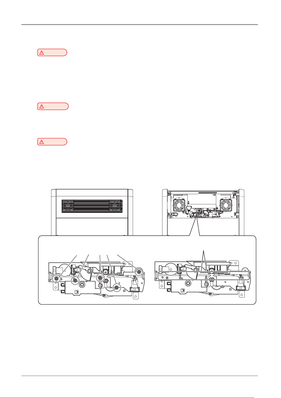
Do not open the rear cover or touch any parts of the extruder unit during machine operation to prevent
-
If you need inspection of the extruder unit, turn off the power and disconnect the power cord and follow
Remove the cover upward.
Remove 5 screws.
Remove filaments that ara blocked.
9
Page 18

Before using the Machine
7. Ventilation
ventilation, this may be harmful for your health. Ventilate it on a regular basis.
ventilation when the machine is used for the first time. If the machine is in operation for an extended
time, do not stay in the same room for a long time.
Caution
-
Use the machine in a place with good ventilation. If the machine is used in a place without good
-
Do not block vents. Inappropriate cooling may lead to high temperatures inside the machine.
-
In general, a new machine may produce small amount of gaseous components, so ensure good
10
Page 19
8. Notices
Before using the Machine
❖
The following are measured in accordance of ISO 7779 and reported to meet ISO 9296.
Some modes may not be available in your purchased products.
Do not dispose the machine and consumables together with household wastes.
For disposal or recycling, contact your local sales office.
Noise Emission Level
Average Sound Pressure at 1 Meter Away
Printing 45dBA(Normal Print Condition - Printing speed 40 mm/s, Travel speed 100 mm/s)
Standby under 40 dBA
Temperature/Humidity
❖
Operation 16 °C ~ 29 °C, 20%RH~70%RH
Shipping
Storage -30 °C ~ 50 °C, Below 80%RH(No condensation, must not touch the floor)
Disposal of The Products
❖
-30 °C ~ 50 °C, 15%RH~95%RH(for 0 °C or lower temperature, room’s temperature should be higher
than the outdoor’s; must not touch the floor)
This machine complies with the limits for Class A.
Class A (Industrial Device) : This is a class A product. In a domestic environment this product may cause radio
interference in which case the user may be required to take adequate measures.
This device complies with part 15 of the FCC Rules. Operation is subject to the following two conditions:
(1) This device may not cause harmful interference, and (2) this device must accept any interference
received, Including interference that may cause undesired operation.
This equipment has been tested and found to comply with the limits for a Class A digital device,
pursuant to part 15 of the FCC Rules. These limits are designed to provide reasonable protection against
harmful interference in a residential installation.
accordance with the instructions, may cause harmful interference to radio communications. However, there
is no guarantee that interference will not occur in a particular installation. If this equipment does cause
harmful interference to radio or television reception, which can be determined by turning the equipment
off and on, the user is encouraged to try to correct the interference by one m ore of the following
measures:
- Reorient or relocate the receiving antenna.
connected.
EMI(Electromagnetic Interference) Notice
❖
FCC COMPLIANCE STATEMET
INFORMATION TO USER
This equipment generates uses and can radiate radio frequency energy and, if not installed and used in
-
Increase the separation between the equipment and receiver.
-
Connect the equipment into an outlet on a circuit different from that to which the receiver is
-
Consult the dealer or an experienced radio/TV technician for help.
11
Page 20
Before using the Machine
CAUTION
Any changes or modifications not expressly approved by the manufacturer responsible for compliance
could void the user’s authority to operate the equipment.
The wireless device may be affected by electromagnetic interference so it should not be used for life
saving services.
Exposure to radio frequency radiation
The following notice is applicable if your printer has a wireless network card installed.
The radiated output power of this device is far below the FCC radio frequency exposure limits.
A minimum clearance of 20 cm (8 inches) must be maintained between the antenna and any persons for
this device to satisfy the RF exposure requirements of the FCC.
Power Consumption of the Products
The below table shows power consumption.
DECLARATION OF CONFORMITY (DOC Letter): 13page
Wireless LAN Specifications
❖
WLAN Notice
❖
Power Consumption
❖
Mode Description Power Consumption(W)
Printing A device is printing using electronic input data. 300W
Standby A device is in standby mode. 20W
Power Off A power plug is plugged into the outlet with the machine’s
switch off .
The above power consumption is the hourly average value.
Instant power consumption can be much higher than the average value.
0.5W
Deactivated Mode
The machine consumes power even in the deactivated mode. Unplug the power cord to completely stop the
power consumption.
Total Energy Usage
It would be useful to calculate the Total energy usage of the machine.
Since the electricity bill is charged in Watt unit, you have to multiply time spent in each mode by power
consumption in order to calculate the energy use.
Total energy usage is the sum of energy used in each mode.
Condensation
Dramatic change of the ambient temperature may produces water droplets on the interior and exterior of the
machine.
door and cover opened.
Wipe the water droplets on the outer surface, but for the inside please let them dry off by leaving front
This equipment is not suitable for use in locations where children are likely to be present.
❖ Safety Notice
12
Page 21

Before using the Machine
13
Page 22

Before using the Machine
9. Disposal of Used Battery
Control board uses a Lithium battery.
Please discard used batteries following the environmentally friendly procedure stated on the manufacturer
guidelines.
To replace batteries, please contact a qualified service engineer.
14
Page 23
10. Wifi Module Disclaimer
Before using the Machine
❖
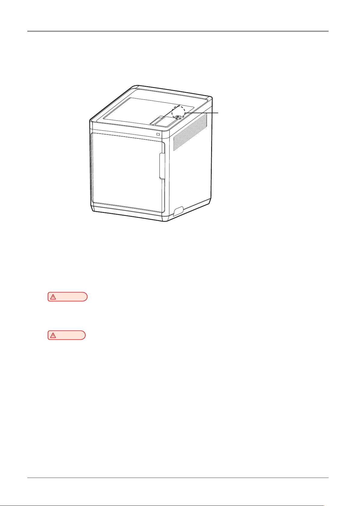
This module includes a Wifi module, compatible only with Sindoh 3DWOX models.
Wifi module inside
❖
This Wifi module can cause radio interference, therefore it should not be used for any purposes related to
human lives.
Do not expose this product to water, humidity or liquid.
Do not expose this product to direct light, hot temperature or fire.
machine trouble or failure.
has been mounted in a place that minimizes human access.
Precautions
Warning
- If the machine has been modified by an unauthorized personnel, Sindoh is not liable for the
Caution
-
To prevent RF signals that exceed FCC RF exposure limits from being exposed to human, this module
15
Page 24
Before using the Machine
❖
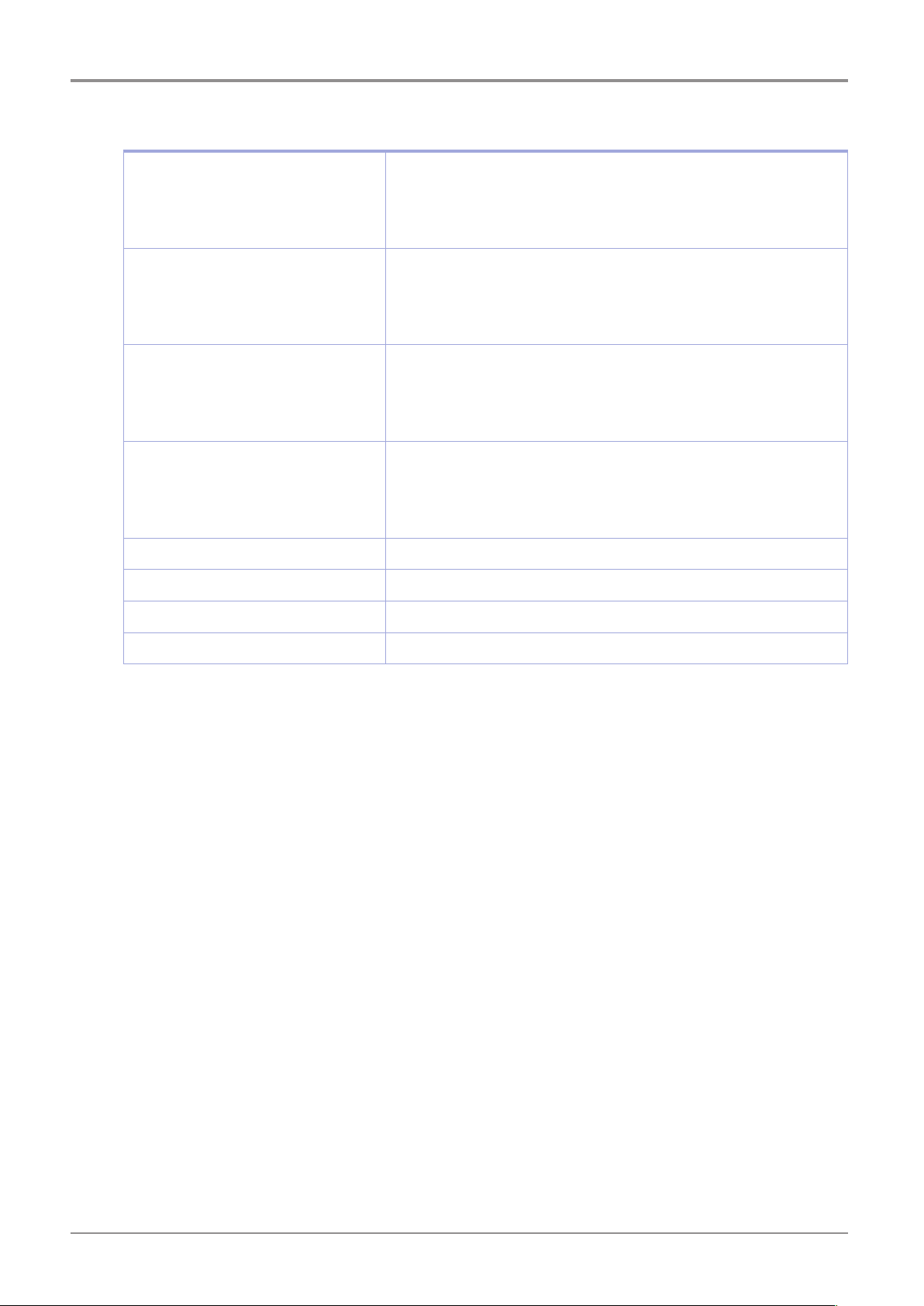
Frequency
Antenna Power Density IEEE 802.11b : 10mW(10dbm)/MHz
No. of Channels IEEE 802.11b : 1
Modulation IEEE 802.11b : DSSS/CCK
Power Consumption 5V 500mA(Maximum)
Precautions
IEEE 802.11b : 2412MHz ~ 2462MHz
IEEE 802.11g : 2412MHz ~ 2462MHz
IEEE 802.11n(20MHz) : 2412MHz ~ 2462MHz
IEEE 802.11n(40MHz) : 2422MHz ~ 2452MHz
IEEE 802.11g : 10mW(10dbm)/MHz
IEEE 802.11n(20MHz) : 10mW(10dbm)/MHz
IEEE 802.11n(40MHz) : 10mW(10dbm)/MHz
1
IEEE 802.11g : 1
IEEE 802.11n(20MHz) : 1
IEEE 802.11n(40MHz) :
IEEE 802.11g : OFDM
IEEE 802.11n(20MHz) : OFDM
IEEE 802.11n(40MHz) : OFDM
1
1
7
Dimension 37.0mm X 28.0mm X 3.7 mm
Operation Temperature 0 ~ 60 °C
Storage Temperature -10 ~ 80 °C
16
Page 25

11. USB Memory Disclaimer
Before using the Machine
❖
This device complies with part 15 of the FCC Rules. Operation is subject to the following two conditions:
(1) this device may not cause harmful interference, and (2) this device must accept
any interference received, including interference that may cause undesired operation.
This equipment has been tested and found to comply with the limits for a Class B digital device, pursuant
to part 15 of the FCC Rules. These limits are designed to provide reasonable protection against harmful
interference in a residential installation.
This equipment generates, uses and can radiate radio frequency energy and, if not installed and used in
accordance with the instructions, may cause harmful interference to radio communications.
However, there is no guarantee that interference will not occur in a particular installation.
If this equipment does cause harmful interference to radio or television reception, which can be determined by
turning the equipment off and on, the user is encouraged to try to correct the interference by one more of the
following measures:
❖
Any changes or modifications not expressly approved by the manufacturer responsible for compliance
could void the user’s authority to operate the equipment.
FCC COMPLIANCE STATEMENT
INFORMATION TO USER
❖
-
Reorient or relocate the receiving antenna.
-
Increase the separation between the equipment and receiver.
-
Connect the equipment into an outlet on a circuit different from that to which the receiver is connected.
-
Consult the dealer or an experienced radio/TV technician for help.
CAUTION
❖
- Please use the enclosed USB flash drive.
The 3DWOX 3D printer does not support USB flash drives in NTFS format.
Specification of compatible USB flash drive for 3DWOX
-
The enclosed USB flash drive is in FAT32 format.
-
The warranty will not be valid if a 3rd party USB drive is used.
17
Page 26

Before using the Machine
IC Identification on Class of ITE
❖
CAN ICES-3 (B)/NMB-3 (B)
Product name : USB Flash Drive
Model name : 8GB-WJ004, 4GB-WJ004
FCC Rules : Tested to comply with FCC Part 15, Class A
Operating Environment : For HOME OR OFFICE USE
FCC COMPLIANCE STATEMENT
This device complies with part 15 of the FCC Rules. Operation is subject to the following two conditions:
(1) this device may not cause harmful interference, and (2) this device must accept any interference
received, including interference that may cause undesired operation.
RESPONSIBLE PARTY
Name : Sindoh America, Ltd.
Address : 6047 Tyvola Glen Circle, Suite #115, Charlotte, NC 28217
Phone No. : 1-704-414-6690
We hereby declare that the above specified equipment with the trade name and model number was tes-
ted conforming to the applicable FCC Rules under the most accurate measurement standards possible,
and that all the necessary steps have been taken and are in force to assure that production units of the
same equipment will continue to comply with the Commission’
Manufacturer : Sindoh Co., Ltd.
Address : 3, Seongsuiro24(isipsa)-gil, Seongdong-gu, Seoul, 04797 REPUBLIC OF KOREA
DECLARATION OF CONFORMITY
s requirements.
18
Page 27

1X Series
USER MANUAL
Preparations for
Machine Operation
1
Page 28

Preparations for Machine Operation
1
1. Machine Specifications
1.1 Printing
Printing Method Fused Filament Fabrication
Max. Print Length(mm) W(max):228, D(max):200, H(max):300
Print Layer Thickness Setting 0.05~0.4mm
Basic Nozzle diameter 0.4mm
Filament width 1.75mm
Printable materials PLA, ABS, FLEXIBLE
Printable color PLA : White, Black, Gray, Red, Yellow, Green, Blue, Pink, Purple
ABS : White, Black, Gray, Red, Yellow, Green, Blue
Flexible: White, Black, Yellow, Green, Red, Orange
Bed leveling Auto measuring + Manual leveling
Print Head One Nozzle
1.2 Temperature/Speed
Continuous Nozzle Usage/ Maximum Temperature Recommended Temperature(Nozzle): PLA 200℃,
ABS 230℃, Flexible 240℃ / Max 270℃
Continuous Bed Usage/ Maximum Temperature Recommended Temperature(Bed): PLA 60℃, ABS 90℃,
Flexible 60℃ / Max 110℃
Recommended printing speed/maximum speed 40mm/s Recommended / 200mm/s max
* Continuous operation at maximum temperature can cause malfunction, Please use in case of nozzle clogging or
other troubles.
1.3 Machine
Power 300W
Dimensions 454 x 468 x 571(W x D x H)
Weight 26kg (excluding cartridge)
Port USB Device, USB Host , Wifi, Ethernet
Cartridge Auto Load / Unload
1.4 Software/Support
Supported Software Sindoh Exclusive Slicer
Supported File Format *.stl, *.ply, *.obj, *.gcode, *.amf
Supported Operating System Windows 7 or above, Mac OSX 10.10 or above
Recommended Memory Requirements DRAM 8 GB+
details on how to use.(https://3dprinter.sindoh.com/support/downloads)
Note
-
Graphics must support OpenGL 2.0 or higher.
-
This product can be utilized with Alexa Echo for hands-free control. Please refer to the below URL for more
1.5 Default Setting of Print layer Width
Nozzle Width 0.4mm
Print Layer Width 0.2mm
1-2
Page 29

2. Basic Components
Please check all basic components are in the box.
Preparations for Machine Operation
1
Caution
-
Please keep the box and packaging material; they are needed for product exchange or repair service.
3D Printer
Cartridge
Power Cable
USB Cable
Reference Guide
Spring Nozzle Cleaner
- The blades of the scrapper can be very sharp. Please be cautious. Please do not use for other than
removing printables.
Please do not touch the blade of the scrapper.
Warning
Scrapper
Tube for Cleaning Nozzle Cleaner
USB Drive
1-3
Page 30

Preparations for Machine Operation
1
3. Understanding the Device Parts
<Front> <Rear>
4
5
3
2
1
6
7
8
9
10
No. Part Name Description
1 Front door handle A handle to open the front door.
2 USB port
Connect USB flash drive containing printing information and print directly from
USB flash drive.
3 LCD Control panel Screen used to control printer.
Caution
-
Usage of printer is recommended after removing the protection film on LCD control panel.
If the film is not removed, the touch screen may not work properly.
4
Power Button
Briefly press this button to turn on printer.
Press and hold for 2 seconds to turn off the printer
Power Button
Indicator
Lamp On Power is On.
1 second interval flickering Can be turned on instantly.
(power cable is connected)
Caution
-
If in case of not using the printer for long period of
time, please unplug the power cord.
-
The lamp may flicker for a few seconds after the
power cord is disconnected.
Lamp Off Inactive Mode. (Power cord is unplugged)
5 Top door handle A handle to open top door.
6 Ventilator fan(Odor
removing filter)
Discharges heat from interior.
Filters out odor created through printing.
7 Lan Port Allows a device to connect to a network using a LAN cable.
8 USB Port Used to connect printer to computer with a USB cable.
9 Power port Power cord connector.
10 Carrying Handles Handles to use when moving the printer.
1
-4
Page 31

<Interior>
3
Preparations for Machine Operation
4
1
1
No. Part Name Description
1 Bed height adjustment Knob Used to level the Flexible bed.
2 Removable bed handle Used to assemble and dismantle Flexible bed
3 Bed heater Heats the printables' bottom surface to stabilize it on the bed.
4 Flexible bed (bed sheet) Seating space for Printable
<Nozzle>
1
2
1
3
2
5
4
No. Part Name Description
1 Body Main body of the nozzle part.
2 Fan 1 Cooling fan for extrusion.
3 Fan 2 Cooling fan for Nozzle heatsink.
4 Nozzle Nozzle for printing.
5 Heater block Nozzle part for filament heating.
1-5
Page 32

Preparations for Machine Operation
1
4. Installation(Product connection, Cartridge Setup and
Software installation)
4.1 Device Connection
Next, connect the power cable to the power outlet.
1) Direct Connection: Connect one end of the enclosed USB cable to the back of the 3DWOX and the other end
to the PC.
2) Network Connection: Refer to 2-25(Network) of the User Manual.
On the rear side of the machine, connect the power cable to the power socket.
1
Press the power button, located on top of the machine.
2
After main menu is displayed on the LCD screen, install the cartridge (Refer to UI manual “LOAD”).
3
Connection to PC
4
Plug USB flash drive in, and install machine drivers and Slicer program.
5
4.2 Program Installation
USB.
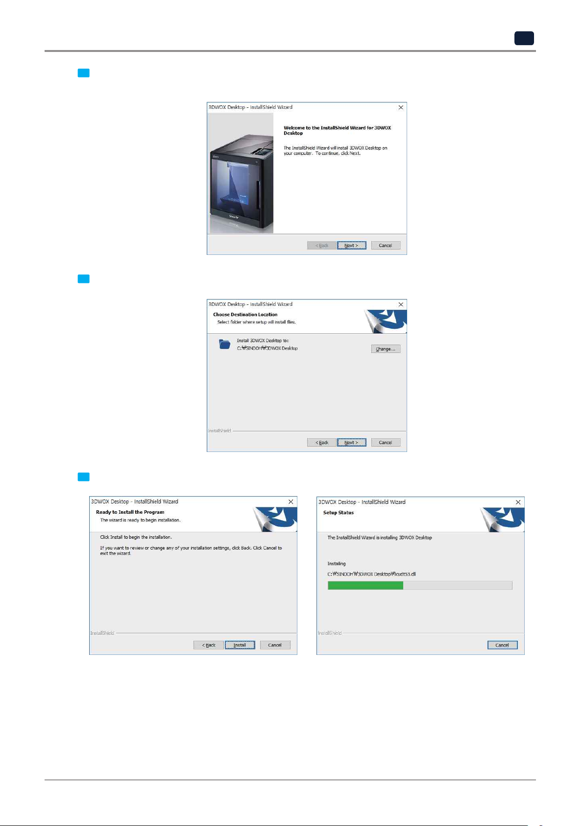
Start the installation of 3DWOX Desktop program by clicking on “3DWOX Desktop.exe” file in the enclosed
1
Install the additional files required by the software first.
2
1
-6
Page 33
Preparations for Machine Operation
1
Press [Next] button to initiate the installation of 3DWOX Desktop program.
When installation of the file is complete, a pop-up window shows up as picture below.
3
Choose the destination location of the file and press [Next] to proceed.
4
The file gets saved and the installation starts.
5
1-7
Page 34
Preparations for Machine Operation
1
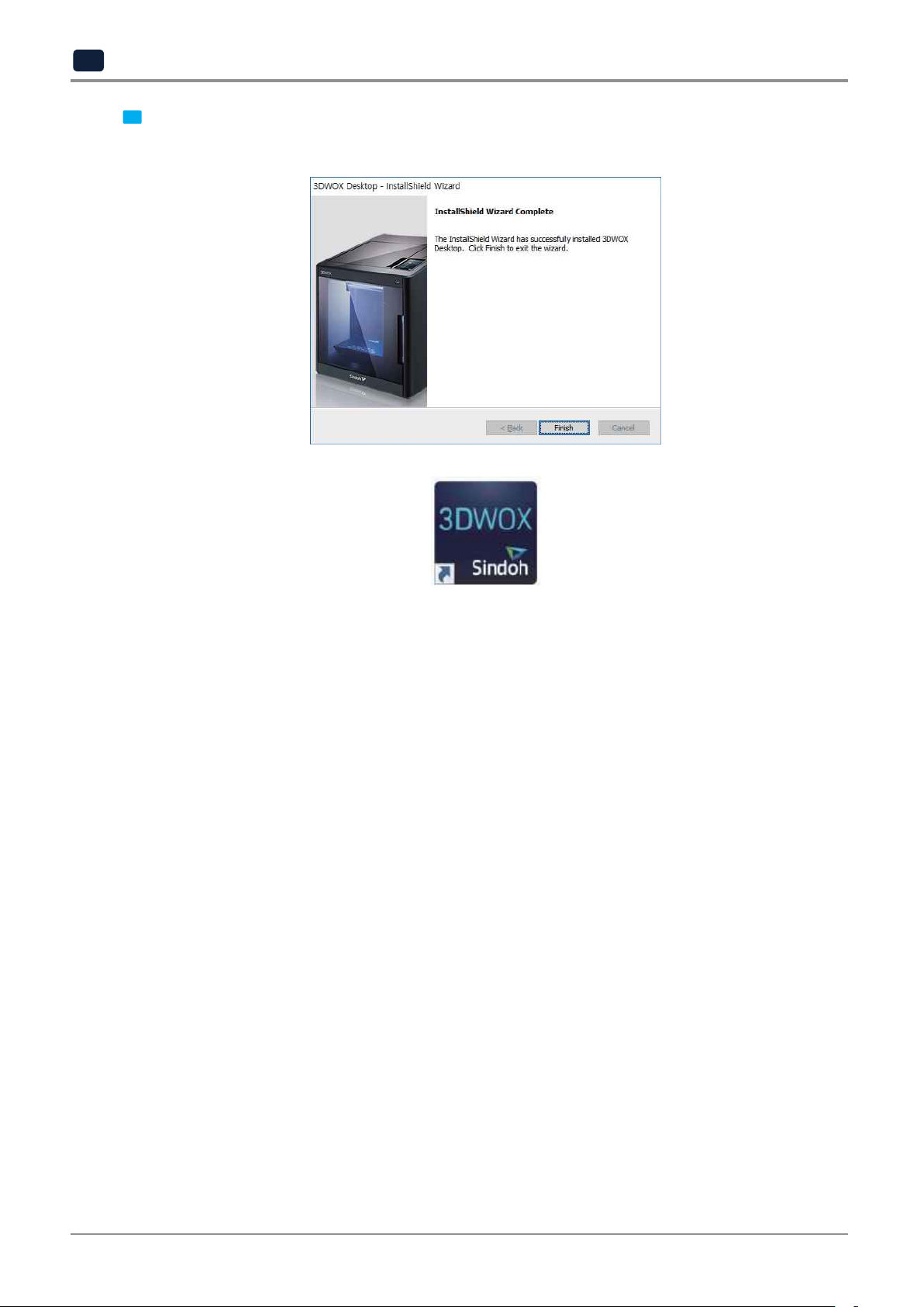
computer.
After all installation is complete, you can see that the “3DWOX Desktop” created on the desktop of your
6
1
-8
Page 35

1X Series
USER MANUAL
UI Menu Function
2
Page 36
UI Menu Function
2
1. UI Menu Function description
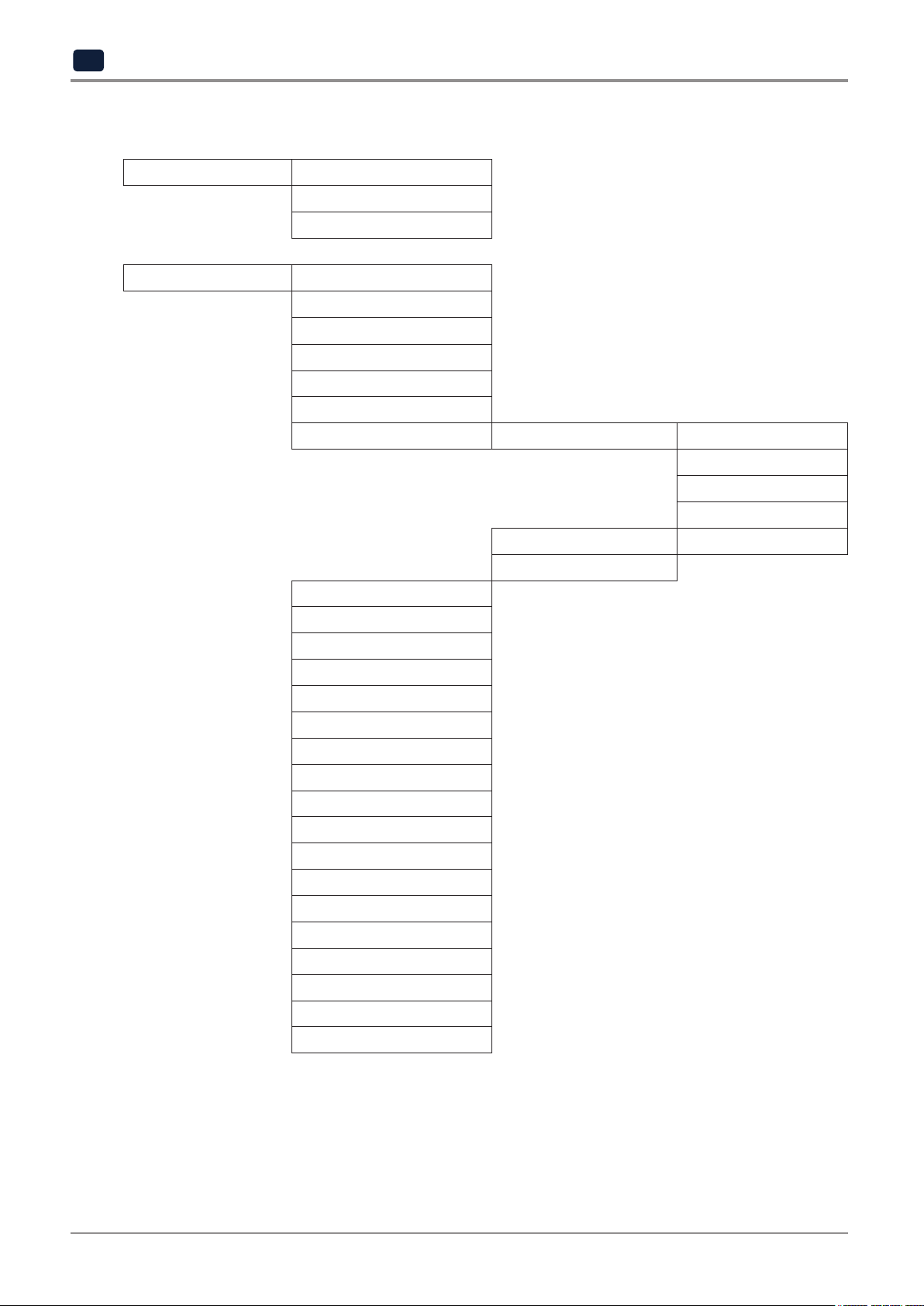
CARTRIDGE LOAD
UNLOAD
UNLOCK
SETTING X Y Z
EXTRUDER
BED LEVELING
Z OFFSET
NOZZLE CLEANING
CLEANING CASE
NETWORK WIRELESS WIRELESS
WIRED DHCP / STATIC
SETTING
BED LOWERING
TEST PRINT
ACTIVE LEVELING
SECURITY
VOICE GUIDE
BEEP SOUND
LANGUAGE
E-MAIL
UNIT
TIME SETTING
TIME ZONE
POWER SAVIG MODE
LAMP
WEB
SOFTWARE UPDATE
NOZZLE REPLACEMENT
CLOUD
OPEN MATERIAL
NETWORK SELECT
DHCP / STATIC
SSID DELETE
2-2
Page 37
Information NAME
CHANGE NAME & PW
MODEL NAME
SERIAL NO.
VERSION
GUI VER.
WIRED IP
WIRED MAC IP
WIRELESS IP
WIRELESS MAC IP
WEB SITE
GUIDE
HISTORY
UI Menu Function
2
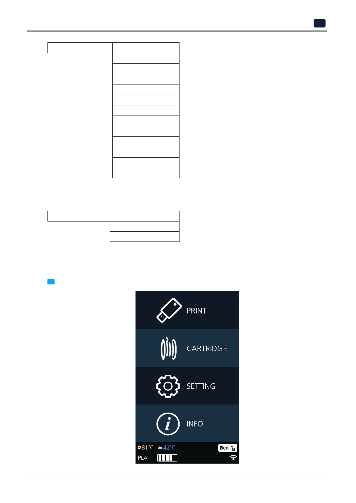
1.1 CARTRIDGE
CARTRIDGE LOAD
UNLOAD
UNLOCK
This function automatically loads filament to the Nozzle.
LOAD
From the HOME screen press [CARTRIDGE].
1
2-3
Page 38
UI Menu Function
2
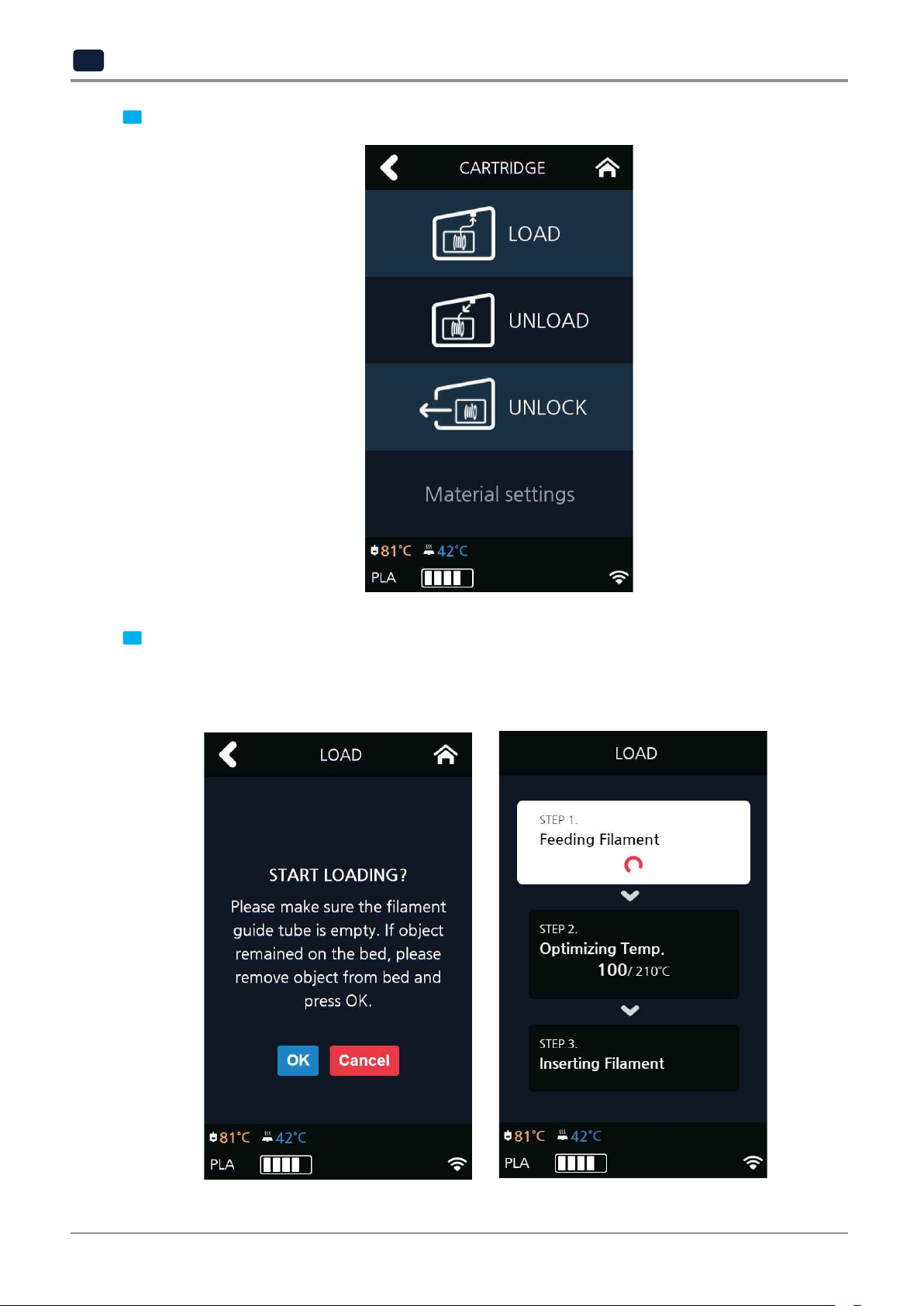
Press [LOAD] to activate Cartridge load.
2
The filament reaches to the nozzle and it is heated up to the specified temperature. Then the filament is
inserted into the heated nozzle. After the process has finished, screen will automatically return to
the [HOME] screen.
When [OK] is pressed at the cartridge load confirming message, cartridge load will automatically proceed.
3
2-4
Page 39

UNLOAD
This function automatically unloads filament from the nozzle.
UI Menu Function
2
From the HOME screen press [CARTRIDGE].
1
Press [UNLOAD] to activate Cartridge unloading.
2
2-5
Page 40
UI Menu Function
2
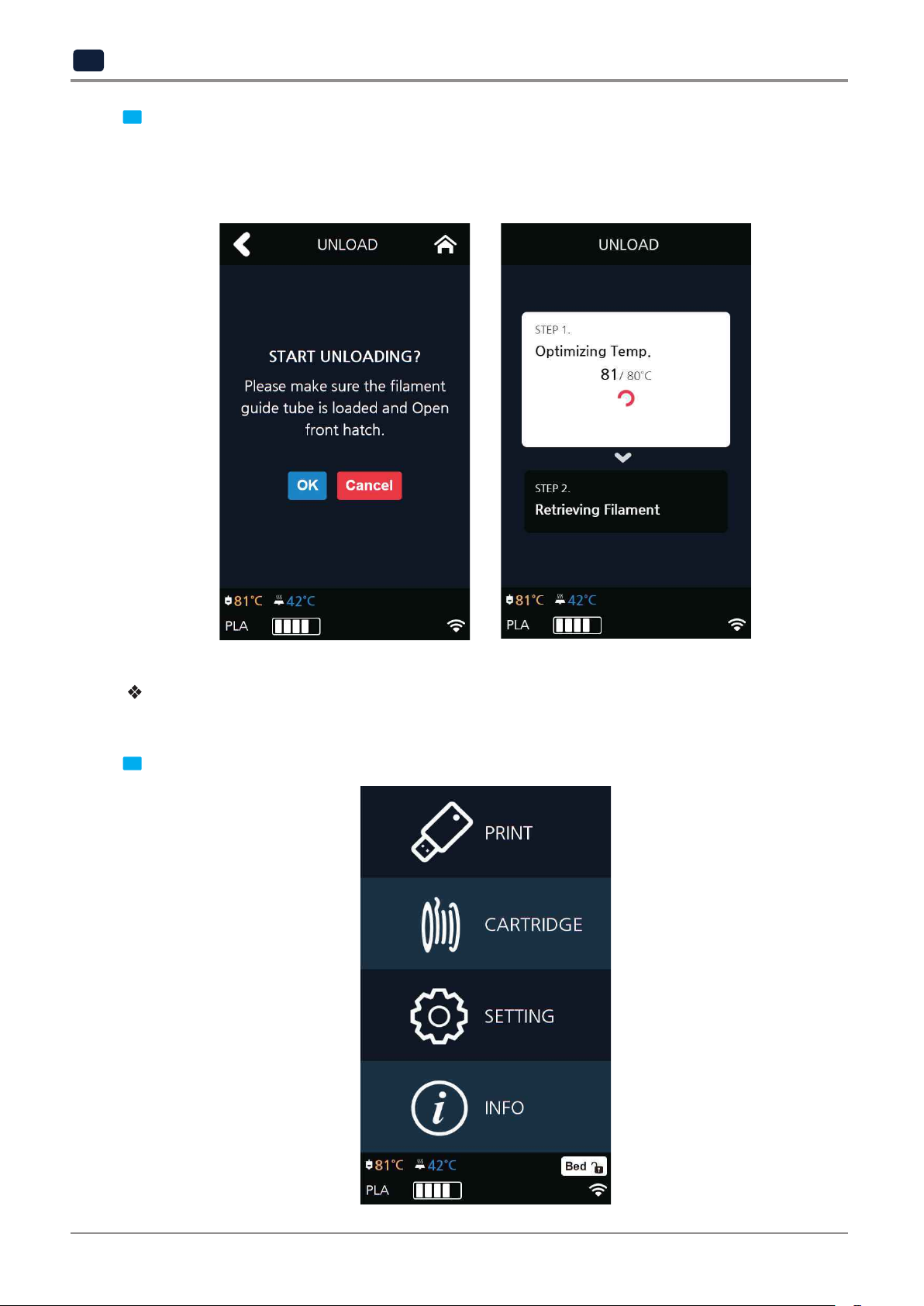
procceed. To remove filament, the nozzle is heated up to the specified temperature and the filament unload
starts.
After the filament has been removed, the screen will automatically turn to the [UNLOCK] screen to let the
When [OK] is pressed at the cartridge unload confirming message, cartridge unloading will automatically
3
user remove the cartridge.
Follow the instructions when you unload soft-materials such as Flexible.
Unload Flexible Filament.
From the HOME screen press [CARTRIDGE].
1
2-6
Page 41

UI Menu Function
2
Press [UNLOAD] to activate Cartridge unloading.
2
Remove the snap ring and tube from the nozzle as shown in the following UI screen, and press the [OK] button.
3
Snap Ring
TUBE
TUBE HOLDER
2-7
Page 42

UI Menu Function
2
Cut the filament that came out of the tube as shown below and press the [OK] button.
4
press the [OK] button.
Reinsert the tube into the nozzle and assemble the snap ring. Push the tube back toward the nozzle again and
5
TUBE
Snap Ring
2-8
Page 43

UI Menu Function
2
remove the cartridge.
After the filament has been removed, the screen will automatically turn to the [UNLOCK] screen to let the user
6
2-9
Page 44

UI Menu Function
2
UNLOCK
This Function is to remove the cartridge out of the printer. Cartridge unlock automatically initiates when
filament unload is finished. Cartridge unlock can also be manually done by the user.
can’t be pulled out even after “unlock”, gently push it forward and then try to pull out again.
When unlock screen automatically appears after cartridge unload.
For 10 seconds [LOCK] state is deactivated and the user can detach cartridge from printer. If the cartridge
1
After 10 seconds printer will automatically change to [LOCK] state and [UNLOCK] appears.
2
2-10
Page 45

UI Menu Function
2
To manually unlock later.
From home screen press [CARTRIDGE].
1
Press [UNLOCK] to activate UNLOCK function.
2
2-11
Page 46

UI Menu Function
2
If the cartridge can’t be pulled out even after “unlock”, gently push it forward and then try to pull out again.
For 10 seconds [LOCK] state is deactivated and the user can detach cartridge from printer.
3
After 10 seconds printer will automatically change to [LOCK] state and [UNLOCK] appears.
4
2-12
Page 47

1.2 Settings
SETTING X Y Z
UI Menu Function
EXTRUDER
BED LEVELING
Z OFFSET
NOZZLE CLEANING
CLEANING CASE
NETWORK WIRELESS WIRELESS
NETWORK SELECT
DHCP / STATIC
SSID DELETE
WIRED DHCP / STATIC
SETTING
BED LOWERING
TEST PRINT
ACTIVE LEVELING
SECURITY
VOICE GUIDE
BEEP SOUND
LANGUAGE
E-MAIL
UNIT
TIME SETTING
TIME ZONE
POWER SAVIG MODE
LAMP
WEB
SOFTWARE UPDATE
NOZZLE REPLACEMENT
CLOUD
OPEN MATERIAL
2
2-13
Page 48

UI Menu Function
2
X, Y, Z
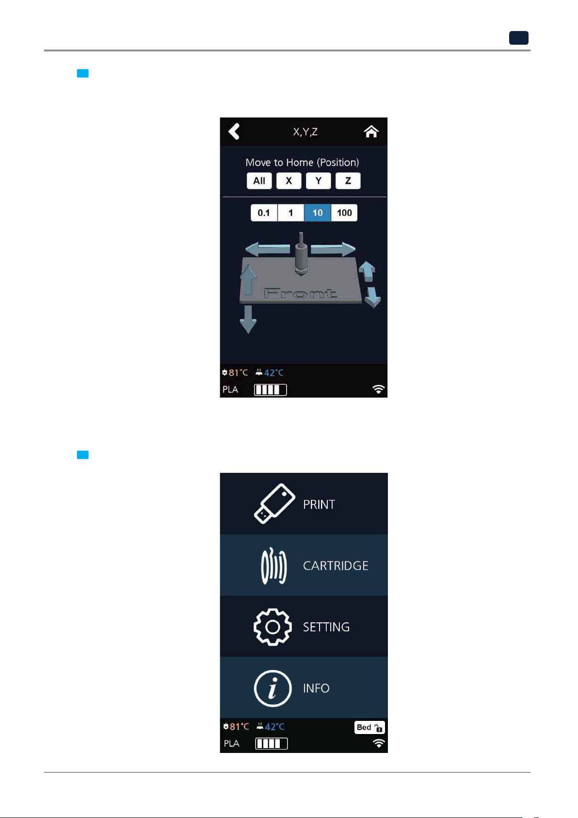
Use to change the positions of the X axis of Nozzle, and the Y, Z axes of Bed.
From home screen press [SETTING].
1
Press the [X,Y,Z] button to enter X, Y, Z.
2
2-14
Page 49
UI Menu Function
2
the Nozzle in the respective position.
To move to each axis' home location, press [All], [X], [Y] or [Z].
Press either [0.1], [1], [10], or [100] to select the length of trasnfer, and press the arrows to move the Bed and
3
EXTRUDER
This function is used to fine control the filament to its position.
From home screen press [SETTING].
1
2-15
Page 50
UI Menu Function
2
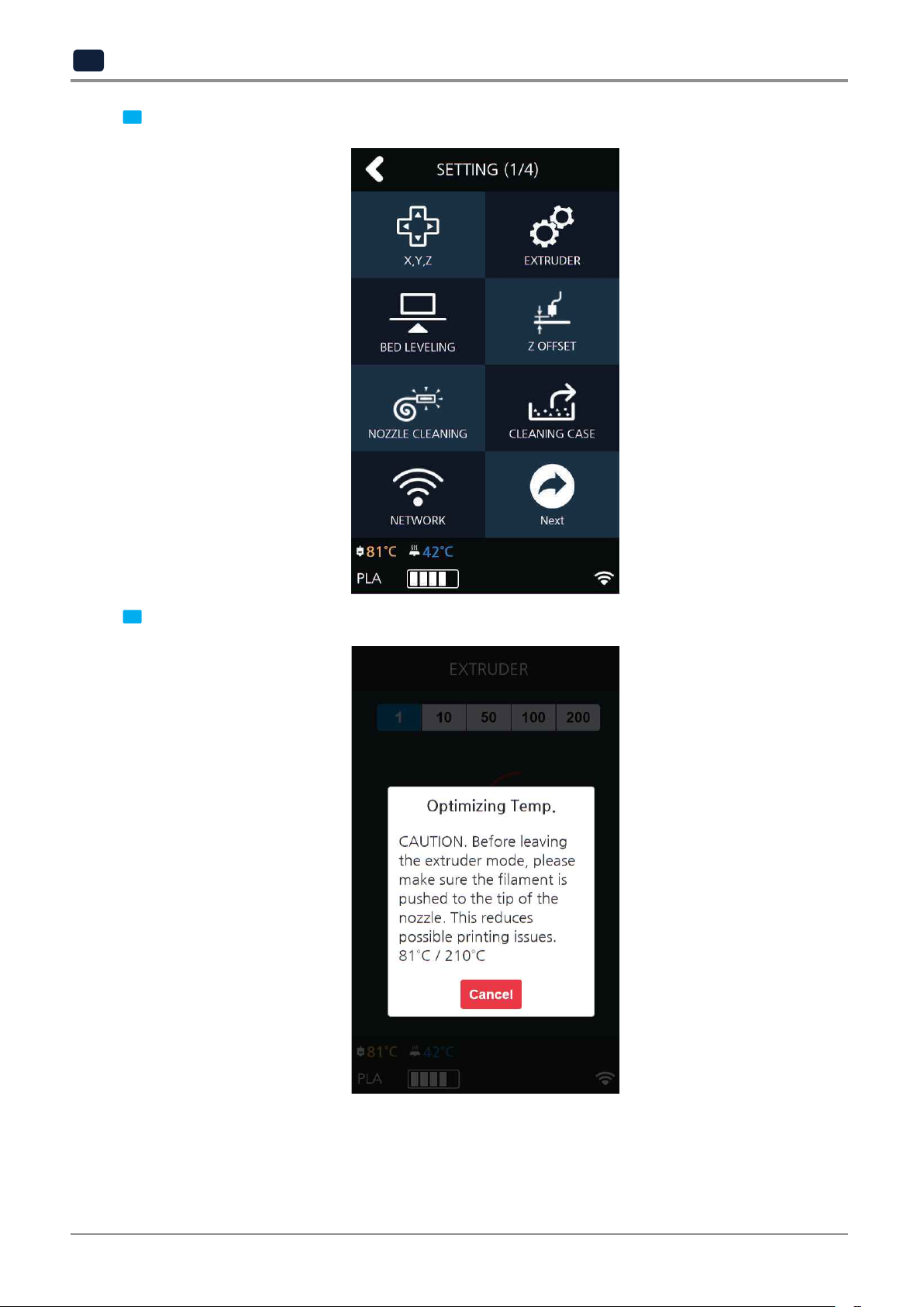
Press [EXTRUDER] to enter EXTRUDER settings.
2
To Control [EXTRUDER], Nozzle temperature needs to be raised.
3
2-16
Page 51
UI Menu Function
2
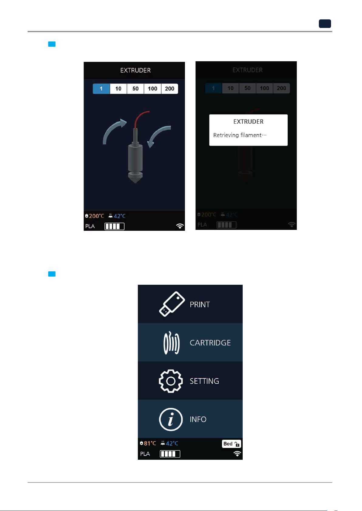
Press [1], [10], [50], [100], [200] to select an amount.
4
In the image shown below
, press the direction to move the filament.
BED LEVELING
This function is used to perform the leveling of the bed.
From home screen press [SETTING].
1
2-17
Page 52
UI Menu Function
2
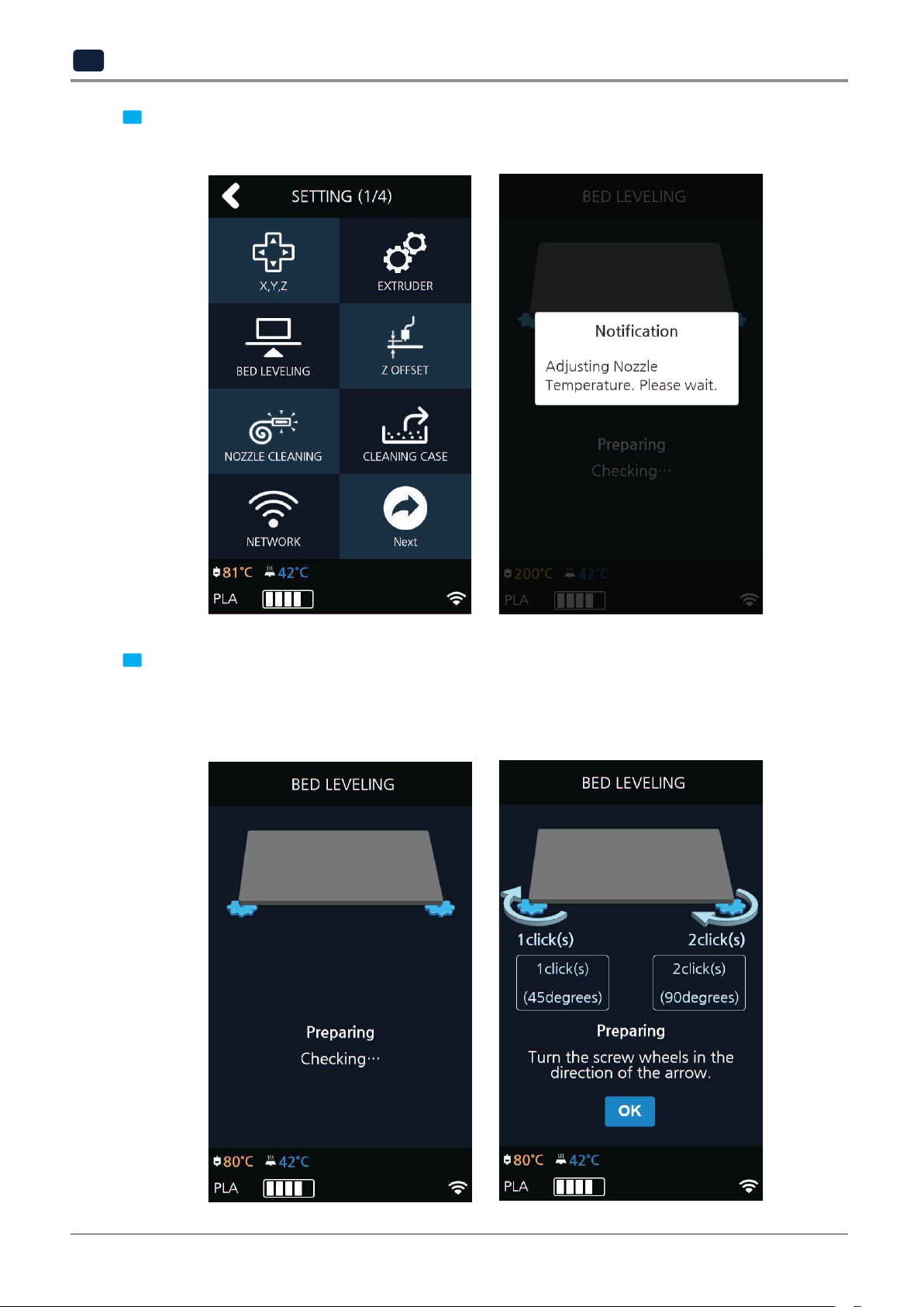
If the current Nozzle temperature is too high, process for cooling down the Nozzle temperature is added.
Press the [BED LEVELING] button to enter BED LEVELING settings.
2
From the center, the top side is measured first, and then both sides of the bottom level are measured.
If the height of the bed is perfect then levelling process will be finished but if the height of the bed and
nozzle does not match, screws will appear informing user the direction and the number of screw rotation.
On the SETTING page, user is able to perform bed leveling. The bed leveling process consists of 3 steps.
3
2-18
Page 53
UI Menu Function
2
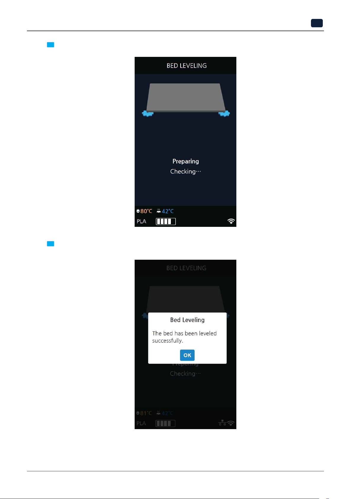
If you turn the screw and press [OK], the measuring is performed and the value to fix appears again.
4
When all settings are done the program returns to the previous screen.
5
2-19
Page 54
UI Menu Function
2
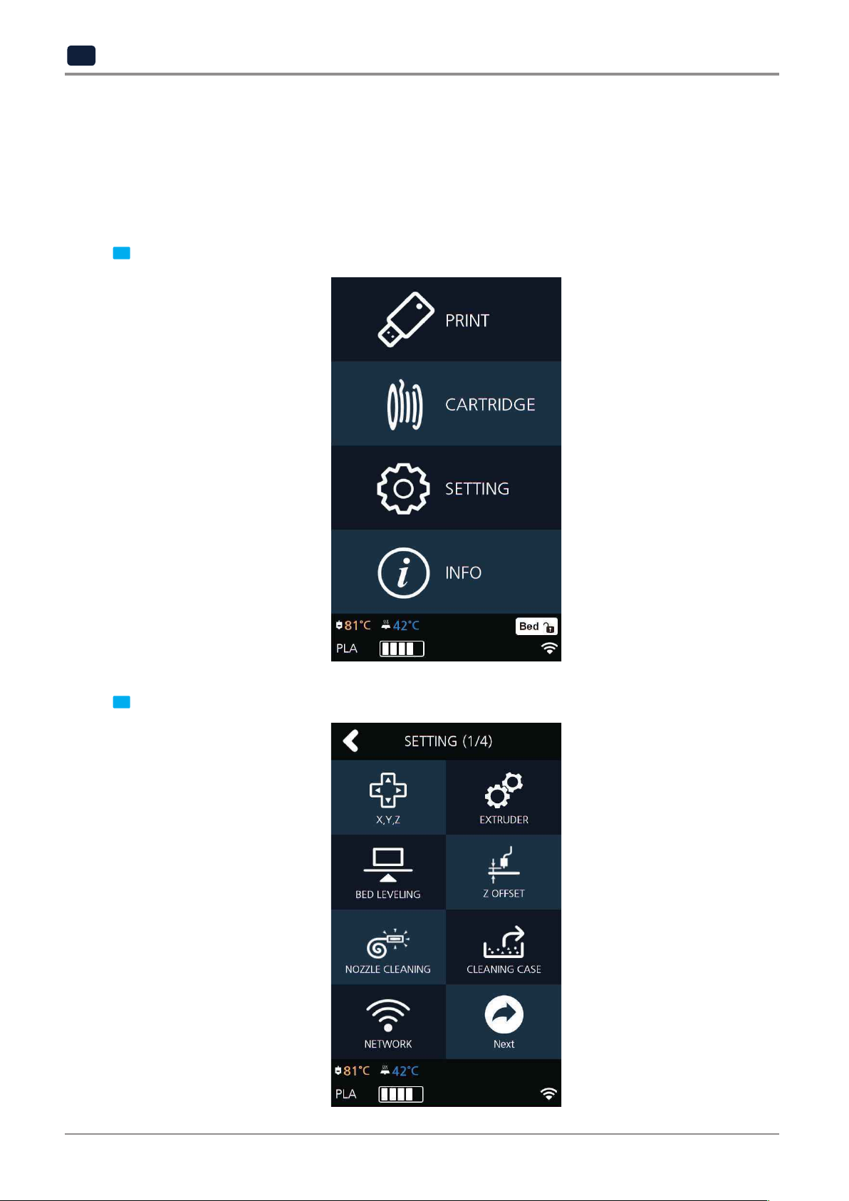
Z OFFSET
※After bed leveling, it is highly recommended to check the z-offset.
This Menu allows user to control the GAP in between Nozzle and BED. Standard is 0.25mm and can be customi
zed. [+] button widens the GAP, [-] button shortens the GAP.
※For higher adhesive strength between the print output and the bed, shorten the distance of the z-offset.
For less adhesive strength, widen the distance of the z-offset.
From home screen press
1
[SETTING]
.
Press the [Z OFFSET] button to access Z Offset screen.
2
2-20
Page 55

UI Menu Function
2
in 0.05 mm unit.
Select the nozzle that you will use to adjust the gap. Default value is 0.25mm, Use [+], [-] buttons to move
3
The saved value is applied when next time the print starts.
These values will be reset if bed leveling is initiated.
Use the [MOVE] and [SAVE] buttons to adjust the gap and to save the setting.
4
2-21
Page 56
UI Menu Function
2
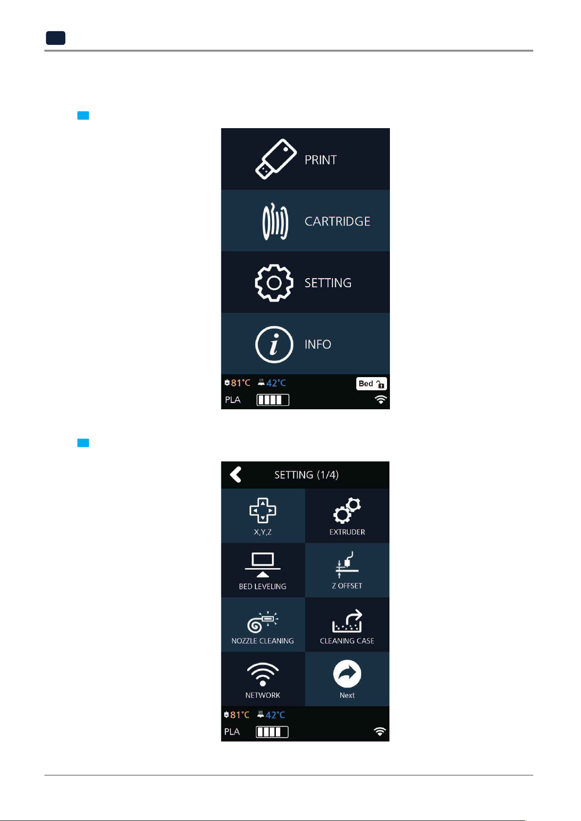
NOZZLE CLEANING
Function used when nozzle needs cleaning of left over filament residue.
From home screen press [SETTING].
1
Press the [NOZZLE CLEANING] button to access nozzle cleaning settings.
2
2-22
Page 57
UI Menu Function
2
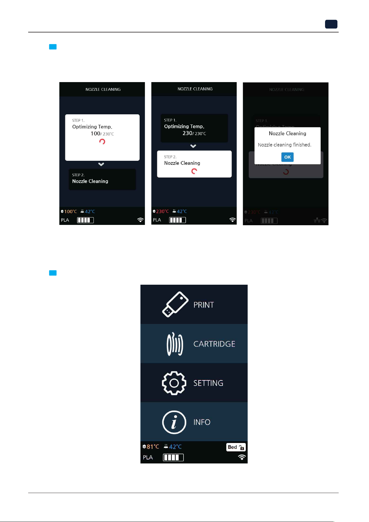
When the specified temperature is reached, it moves on to the next step to remove filament residue.
Once finished message will appear press [OK], printer will return to the settings screen.
In order to get rid of filament residue, the nozzle needs to be heated.
3
CLEANING CASE
Function used to clean out the case for the collected filament residue.
From home screen press [SETTING].
1
2-23
Page 58

UI Menu Function
2
Press the [CLEANING CASE] button to enter CLEANING CASE settings.
2
accessible. Like shown in the image, empty the CASE, press [OK] when done and user will be returned to
the home screen.
Entering Cleaning Case, the nozzle will automatically position itself to the right side to be visible and
3
2-24
Page 59

UI Menu Function
NETWORK
This is a menu to configure users network setting. IP address can be set up manually or automatically via DHCP
setting. Wifi network is also supported.
2
From home screen press [SETTING].
1
Press the [NETWORK] button to access network configuration screen.
2
2-25
Page 60

UI Menu Function
2
Press [DHCP] for automatic IP address setup. To manually input a fixed IP address press [Static] and enter an
IP address. Press [Connect] to save the changes.
The default network setting is Wired (connection using LAN line).
3
Wifi setting can be turned ON or OFF.
In any case to use Wifi press the [Wifi] tab.
4
2-26
Page 61

UI Menu Function
2
To select a Wifi network, click [Choose a network…] and the printer shows all available Wifi connections.
5
a dialog pops up and asks for the password.
You can refresh the network list by clicking [Search].
Select a wireless network from the list to connect to the network. For a password-protected network,
6
When all settings are finalized press [Connect] to save settings.
After successful connection printer may ask for [DHCP], [Static] similar to the WIRED setting.
7
2-27
Page 62

UI Menu Function
2
BED LOWERING
Use this function, in times of moving printer to a different location.
Bed will be lowered to the bottom and will be locked into position.
Press [SETTING] from the home screen.
1
Press [Next] to move to next page, where the [BED LOWERING] button is located.
2
2-28
Page 63

UI Menu Function
2
Upon selection, the bed will automatically be lowered.
3
TEST PRINT
This function allows the user to test print a sample model already saved in the printer.
From home screen press [SETTING].
1
2-29
Page 64

UI Menu Function
2
Press [Next] button to move to the next page and press [TEST PRINT].
2
Select the test file to print.
3
2-30
Page 65
UI Menu Function
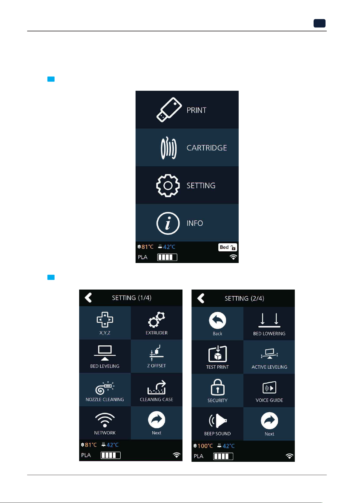
ACTIVE LEVELING
This function executes Bed leveling before printing starts and offset the bed leveling by moving the bed in the
direction the Z-axis during the printing.
2
From home screen press [SETTING].
1
Press the [Next] button to access [ACTIVE LEVELING].
2
2-31
Page 66

UI Menu Function
2
After setting
3
[On/Off]
of the Active Leveling, and then press the
[OK]
button.
SECURITY
This menu enables you to set up the Security menu whether to use the 3D printer or not.
From home screen press [SETTING].
1
2-32
Page 67

UI Menu Function
2
Press the [Next] button to access the [SECURITY] Screen.
2
After setting [On/Off] of the Security, and then press the [OK] button.
3
Reference
-
*Initial password is ‘0000’.
-
For how to reset the password, see page 2-58.
2-33
Page 68
UI Menu Function
2
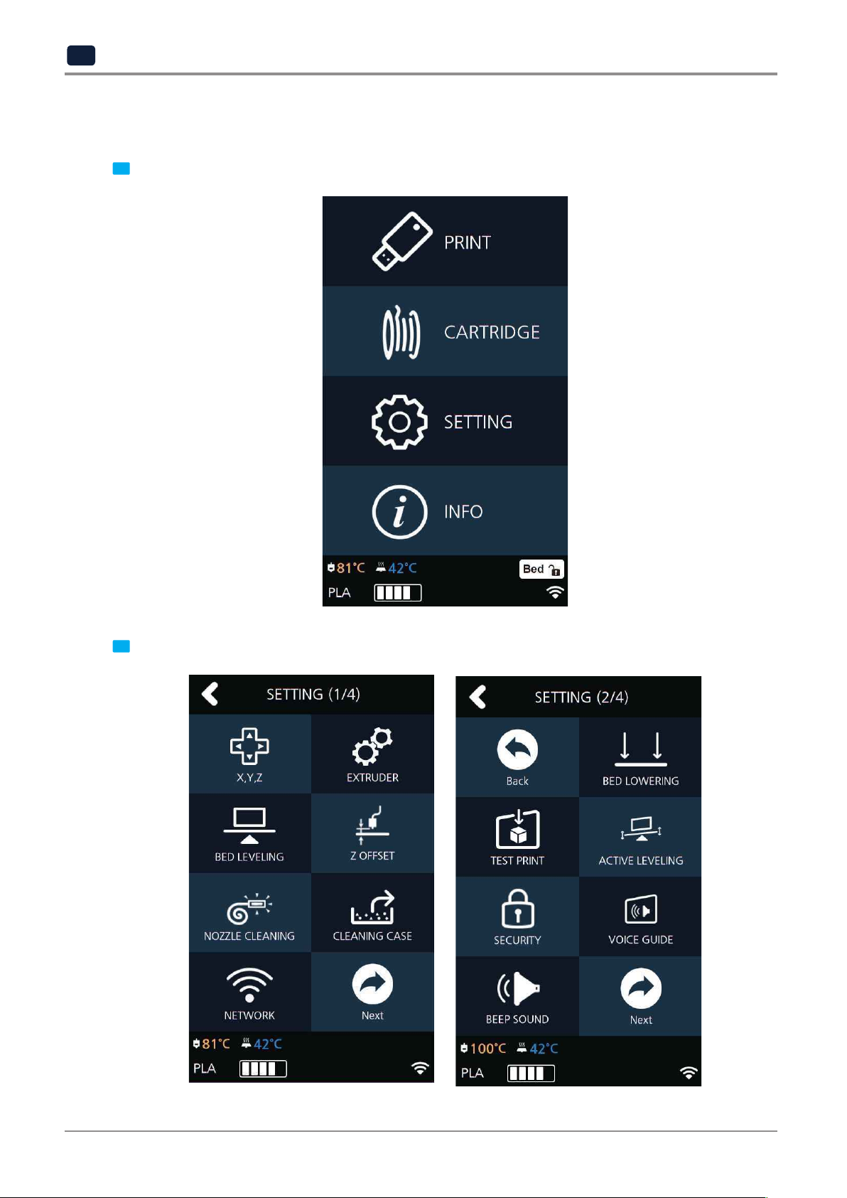
VOICE GUIDE
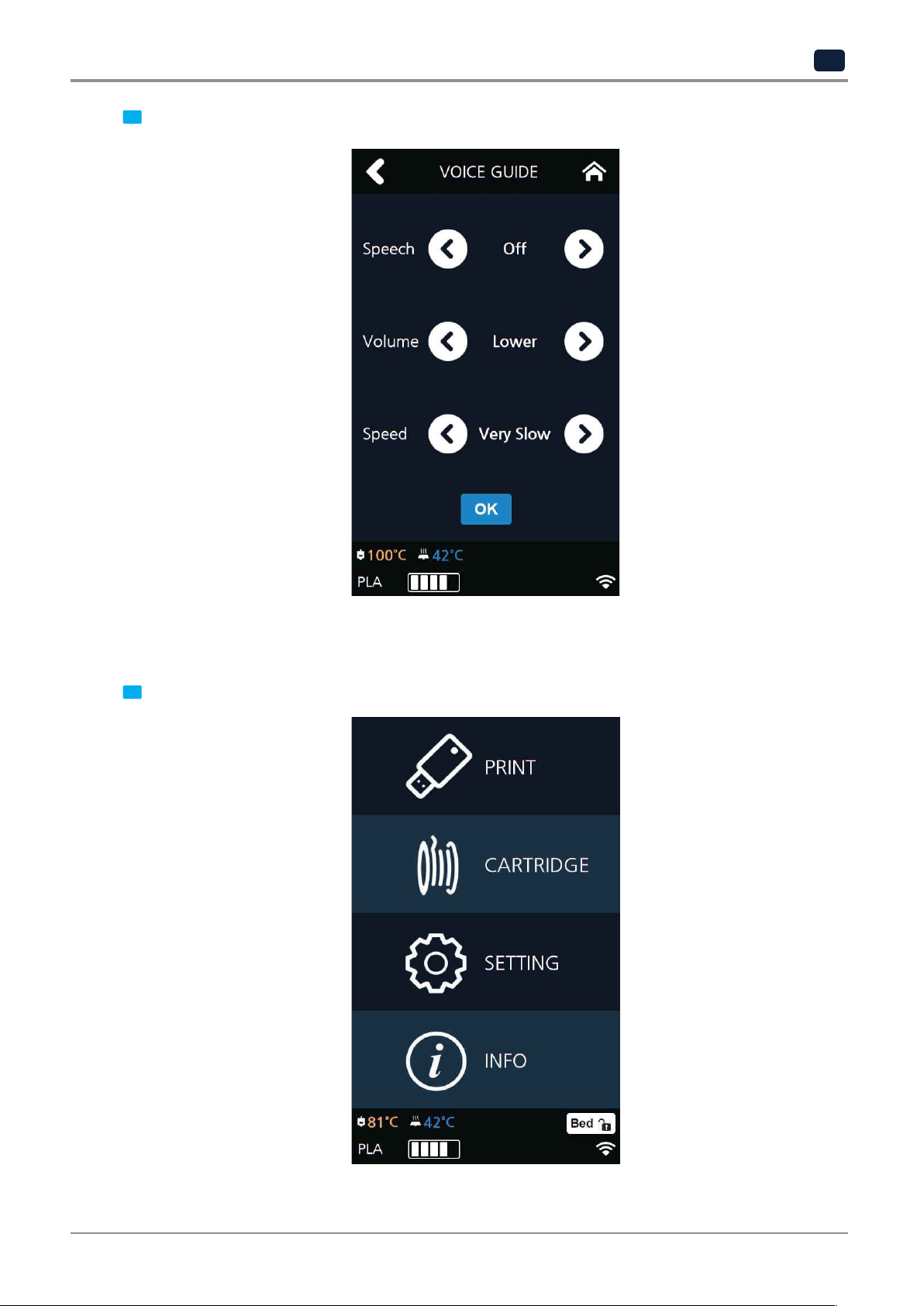
This menu enables you to configure the sound of Voice Guide in the machine.
From home screen press [SETTING].
1
Press the [Next] button to access the [VOICE GUIDE] screen.
2
2-34
Page 69
UI Menu Function
2
After setting your printer’s speech, volume, and speed, press the [OK] button.
3
BEEP SOUND
The volume level of beep sound can be adjusted using this menu.
Press [SETTING] button from the home screen.
1
2-35
Page 70
UI Menu Function
2
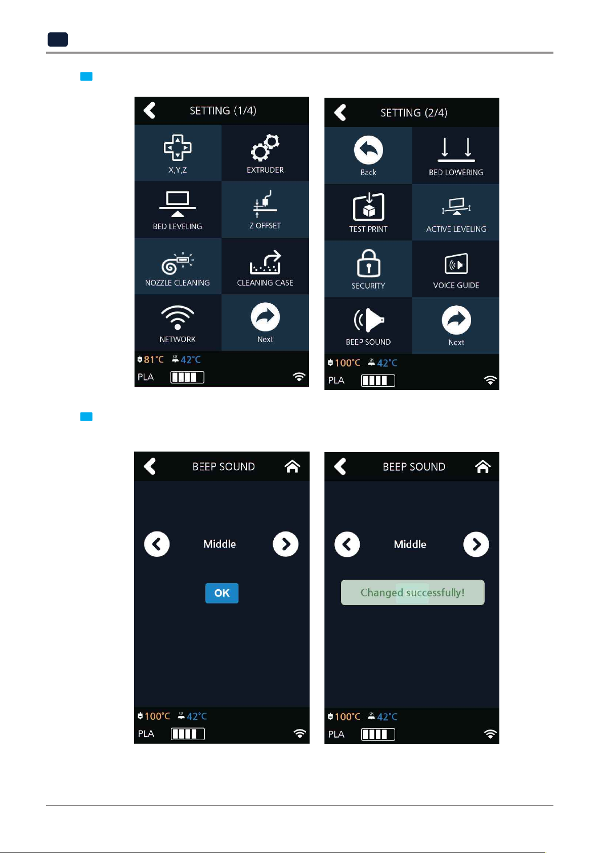
Tap on the [Next] button to move to next page, and press [BEEP SOUND]
2
Select the desired setting and press the [OK] button to save settings.
Currently available sound settings are Low, Middle, High and Off.
3
2-36
Page 71
LANGUAGE
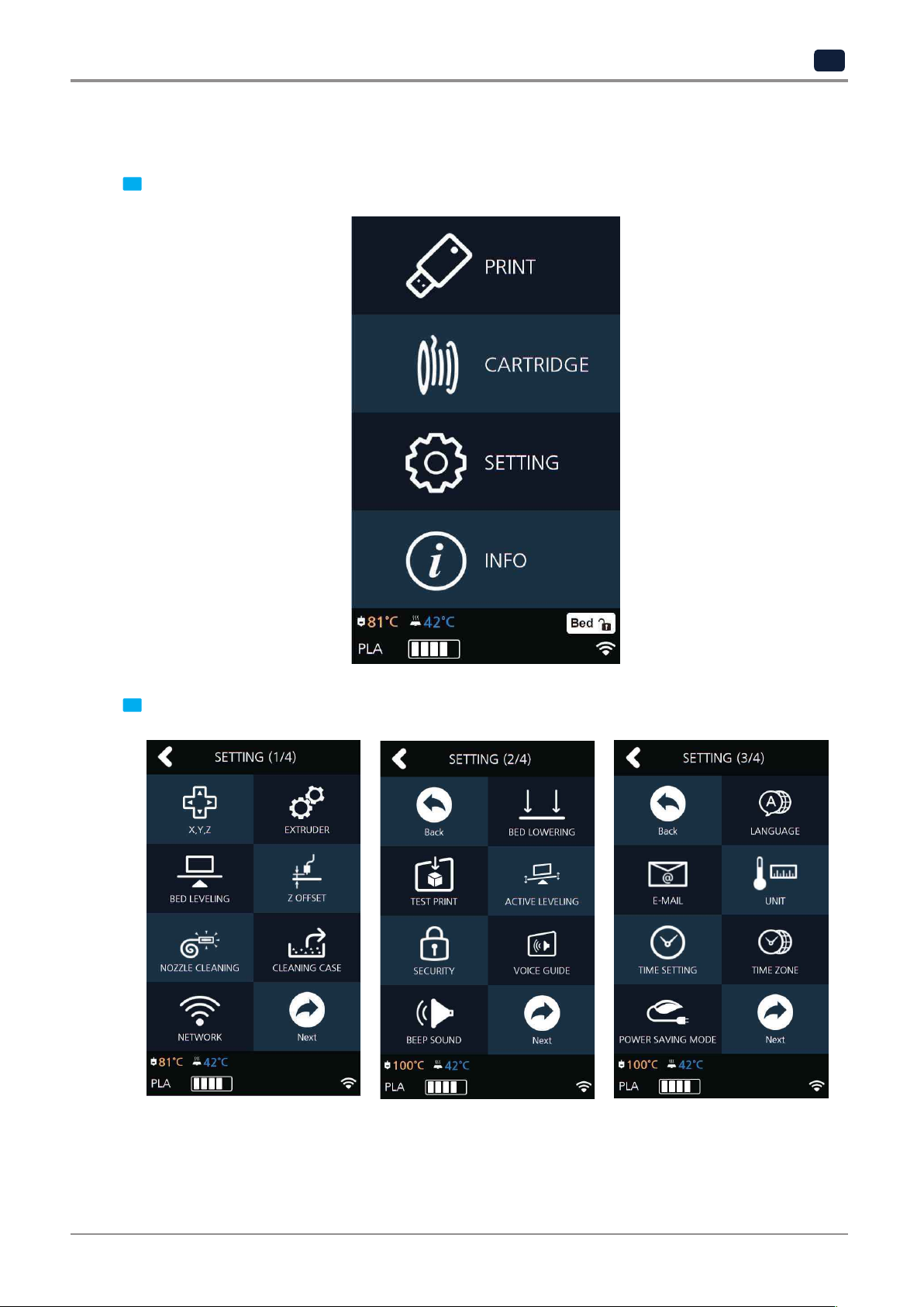
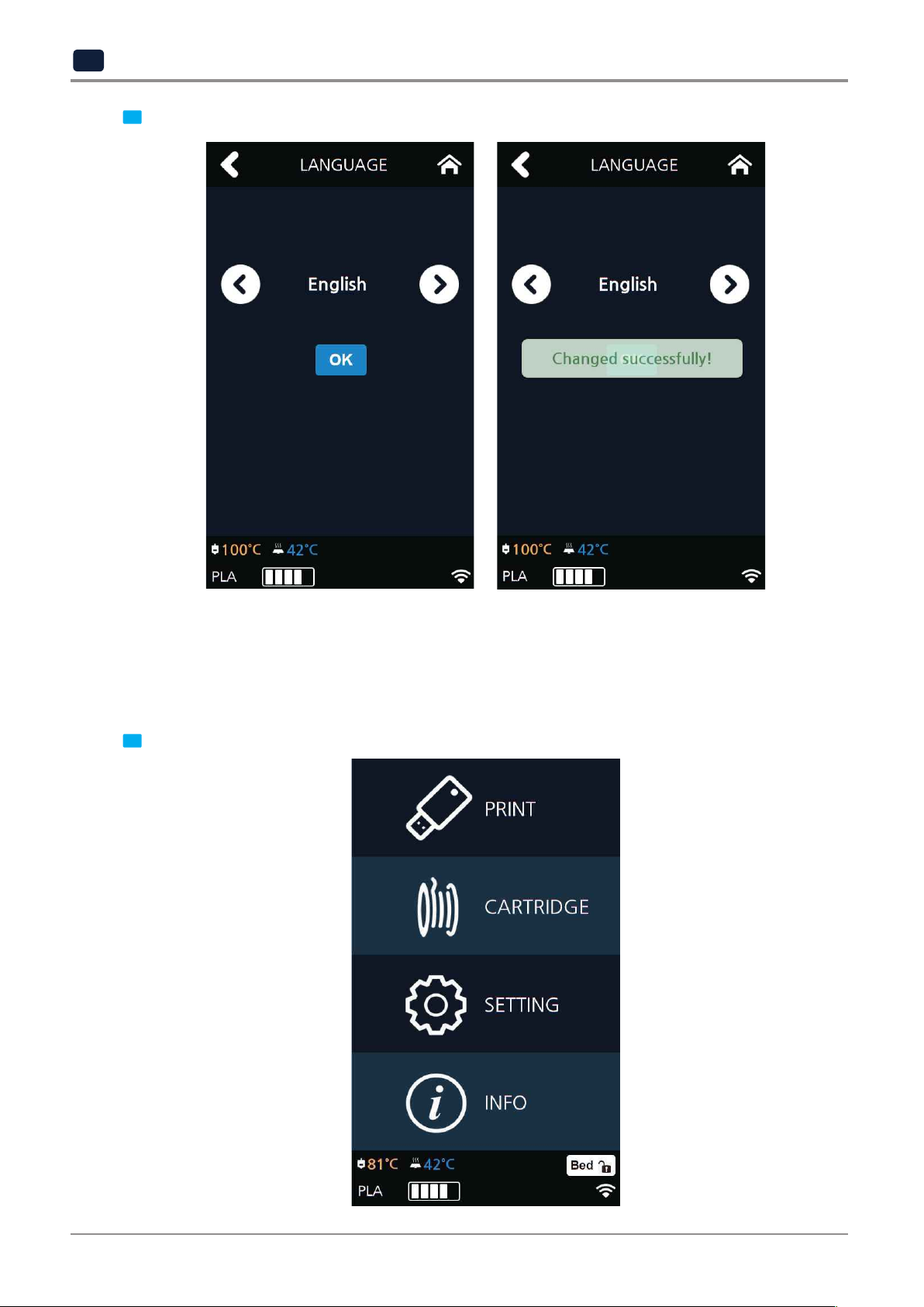
Menu to set language for machine.
UI Menu Function
2
From home screen press [SETTING].
1
Press [Next] 2 times to go to the screen where the [LANGUAGE] menu is.
2
2-37
Page 72
UI Menu Function
2
Using the arrows select a language and press [OK].
3
E-MAIL
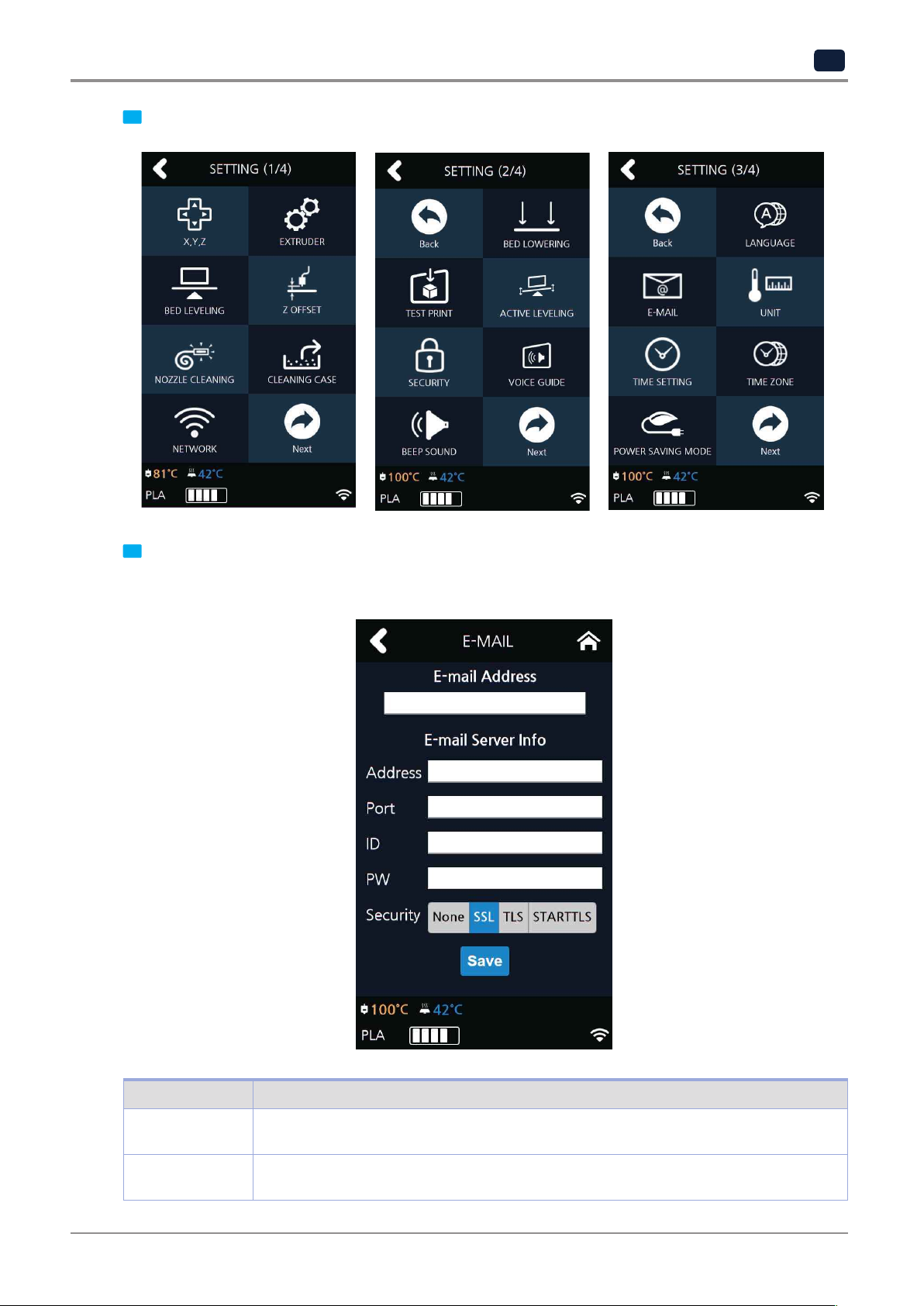
The printer takes an image of the current printing status and sends the information to the email address
specified.
Printer will send information of completion (%) based on the PC program standard settings. Maximum of 10
emails can be sent.
From the home screen, press [SETTING].
1
2-38
Page 73
UI Menu Function
2
Only the information that is required for sending the email is set up from the printer and the recipient
information has to be configured in the Slicer program.
Press the [Next] 2 times and select [E-MAIL].
2
Configure the setting for email notification to be sent out from the device.
3
Catergory Description
E-mail Address The sender info to be seen by the recipient(e.g. [email protected])
The recipient can reply to this email address
Address SMTP server address (e.g. smtp.domain.com)
- This is the server address of the email service ([email protected])
2-39
Page 74

UI Menu Function
2
Port SMTP Server Port (e.g. 25)
ID SMTP server login ID (e.g. sender)
PW SMTP server login password (e.g. ********)
Security Security method used when sending mail to SMTP server
- Normally the port number 25, 587 or 465 is used.
Due to the increased security, some service providers do not allow the use of
port number 465. If port number 465 is not available, please use 25, 587 or the
port number that the service provider recommends.
- Enter the ID for your email.
- Depending on the service provider, a full email address may be requested.
Please contact server administrator or email service provider for more information.
- Enter the password for your email
-The default value is [None]. For further details, contact your server hosting company or
mail service provider.
Inquire your email server administrator or services provider for detailed
on each category. Especially for SMTP server log in ID, it may be needed to enter the entire email address
which includes the domain name.
This setting is for the SMTP (Simple Mail Transfer Protocol) server to be used for sending emails. The SMTP
setting may have to be enabled depending on the system.
To check the detailed setting values, please refer to the setup information from your email service provider.
For the set up to use the outgoing email service, please find information by internet search or your email service
provider’s instructions.
A certain amount of interval time may be required after setting up the SMTP service before using.
For more details, please inquire your email provider for the service policies.
Configure the recipient email information from the 3DWOX slicer program.
4
information of the input information
Under [E-mail], input the recipient email address(es) and select the number times that you wish to send the
notification emails.
Additional recipient addresses can be added by using semicolon.
The maximum number of notification emails that can be sent is 10.
Regardless of the number entered for the email notification, an email will be sent out for the user to see if
number that the user entered. However, the total number of e-mail that is sent will not exceed 10 times.
(When user selects 10 times, the notification e-mail will be sent out 10 times)
the initial email notification is working properly by default. e-mail will be sent out one more time than the
2-40
Page 75

UI Menu Function
2
According to Gmail policies, the following settings have to be met.
After click on "My Account"
In the case of using a Google email account.
▣
Google account setting
Log into your Google account that you are planning to use.
1
Click on the apps button on the top right hand corner.
2
Under "Sign-In&Secruity" click "Device activity & notifications"
3
Scroll down and there is a "Allow less scure apps" criteria. Set it to "On" to enable the option.
4
2-41
Page 76

UI Menu Function
2
information please contact service administrator.
▣
Printer Setting
Set "smtp.google.com" for the settings of the email address.
1
For Google, 25 and 587 ports are compatible.
2
Caution
-
According to the service provider, the email address and port number may be changed. For more
UNIT
Settings for the units of measurments displayed on the printer.
From the home screen, press [SETTING].
1
2-42
Page 77

UI Menu Function
2
Press [Next] 2 times and select [UNIT].
2
The units for temperature and length can be changed.
3
2-43
Page 78

UI Menu Function
2
TIME SETTING
You can view or change the time setting.
From the home screen, press [SETTING].
1
Press [Next] 2 times and select [TIME SETTING].
1
2-44
Page 79

UI Menu Function
2
The time setting can be changed in this screen.
3
TIME ZONE
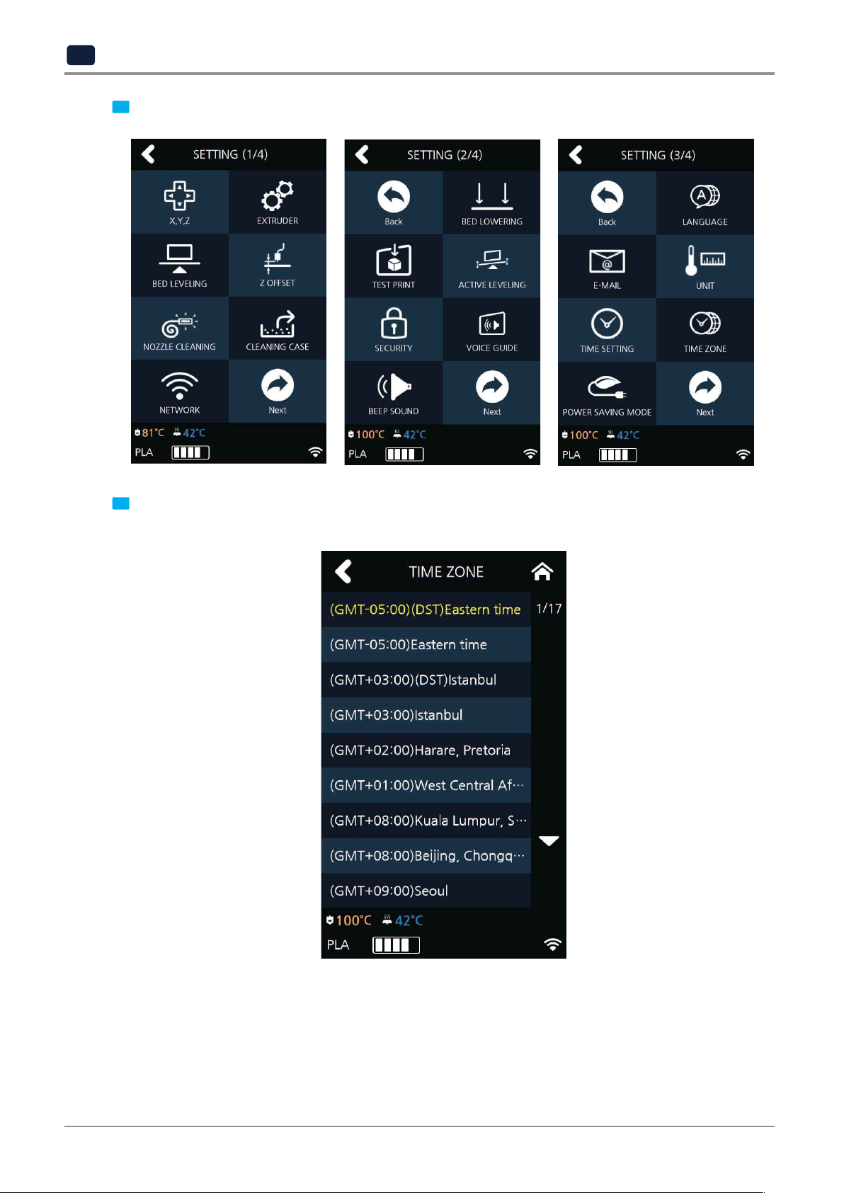
You can view or change the time zone setting.
From the home screen, press [SETTING].
1
2-45
Page 80
UI Menu Function
2
Once Time Zone has been set, the printer will restart to apply the new settings.
Press [Next] 2 times and select [TIME ZONE].
2
A preferred time zone can be selected from the time zone list.
3
2-46
Page 81

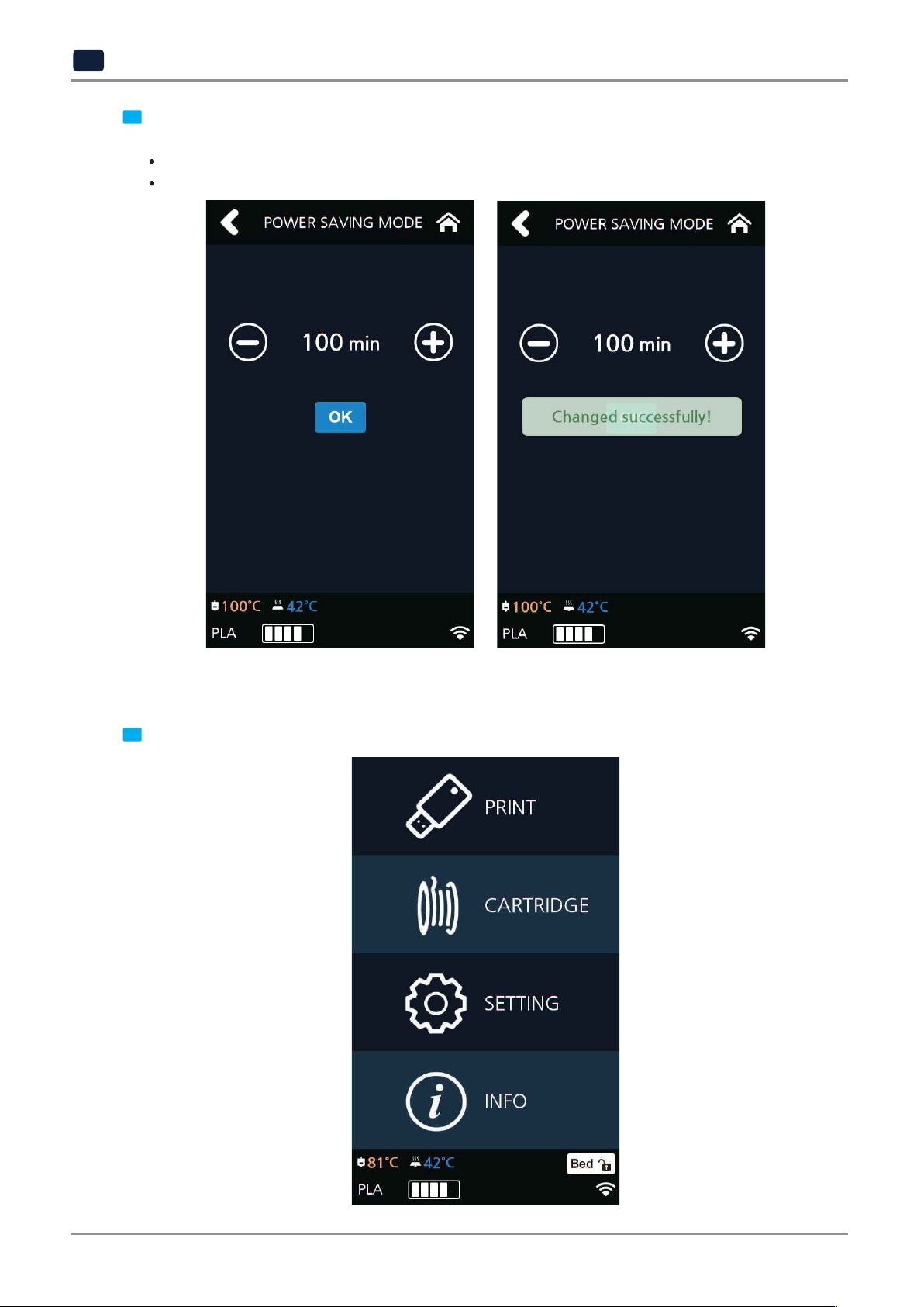
POWER SAVING MODE
Function to set timer for printer energy saver mode.
UI Menu Function
2
From home screen press [SETTING].
1
Press [Next] button to move to the next page and press [POWER SAVING MODE].
2
2-47
Page 82
UI Menu Function
2
select the desired time using the [ +, - ] then press [OK] button to save changes.
The adjustable values of energy savor mode are [0 ~ 100 min]. The time can be adjusted in 5 min unit,
3
0 Min : Do not use Energy Saving Mode
5~100Min : Energy Saving Mode in 5 ~ 100 Min. of Inactivity.
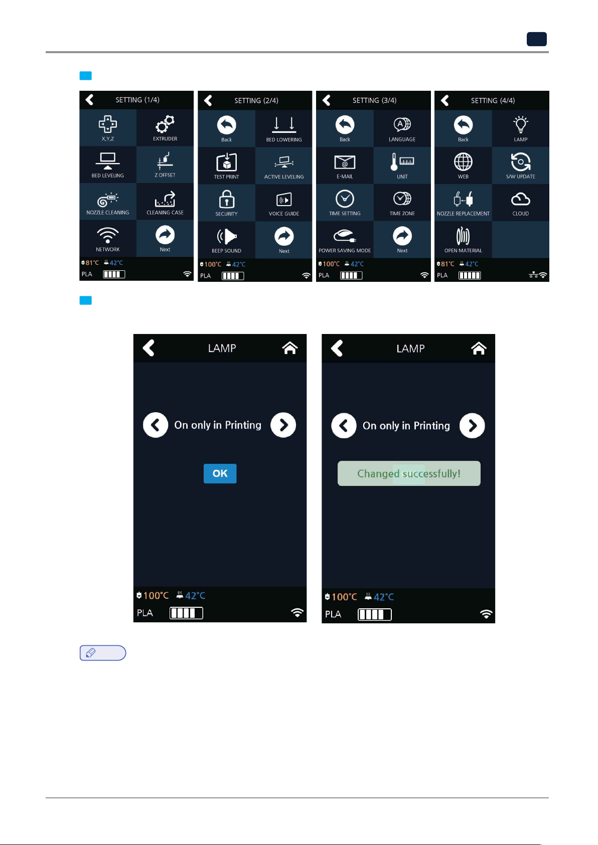
LAMP
Menu to configure settings for machine lamp.
From home screen press [SETTING].
1
2-48
Page 83
UI Menu Function
2
select an option and press [OK].
Press [Next] to enter [LAMP] setting screen.
2
Settings available for [LAMP] are [Always On], [Always Off], and [On only in printing]. Use arrow buttons to
3
Note
-
Lamp will be activated as connecting the Web Monitor.
2-49
Page 84
UI Menu Function
2
WEB
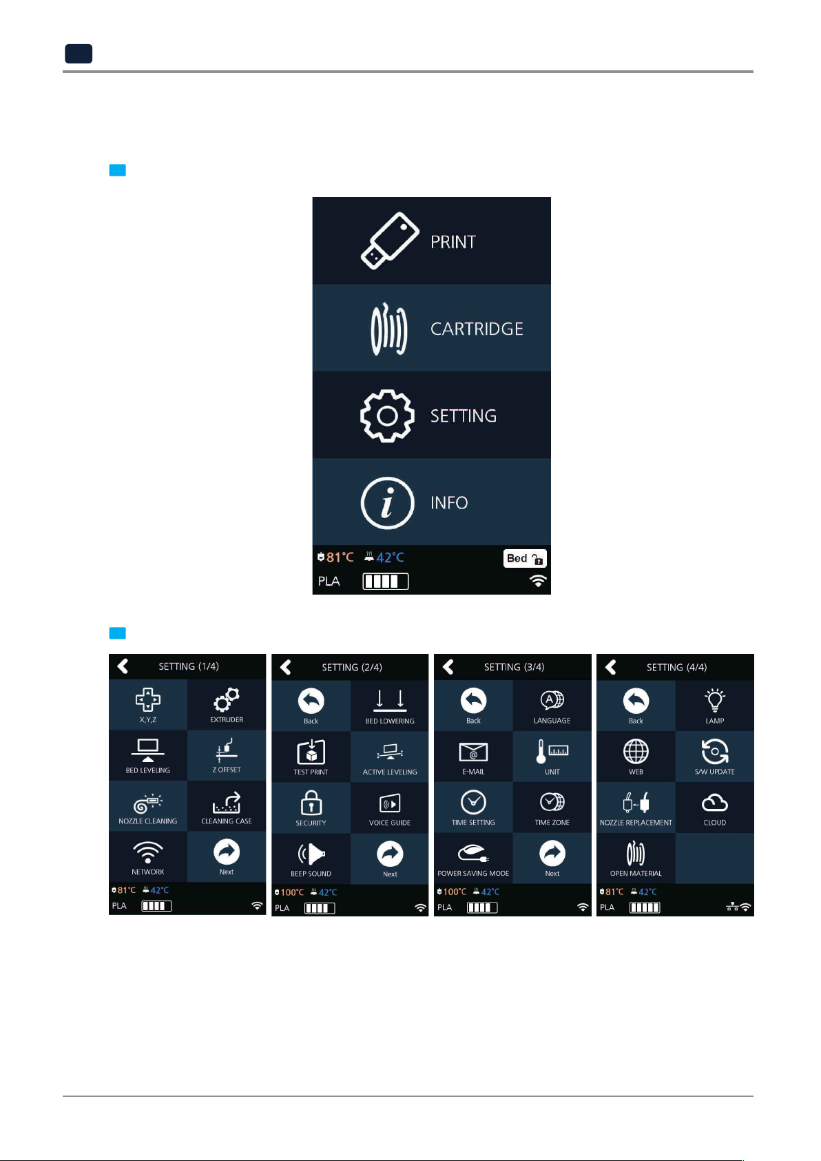
While network is connected, I can open the internet browser tab in the Firmware to load 3D Printer homepage.
From the home screen, enter the settings menus by pressing the [SETTING] button.
1
Press the [Next] and enter the [WEB] menu.
2
2-50
Page 85
UI Menu Function
2
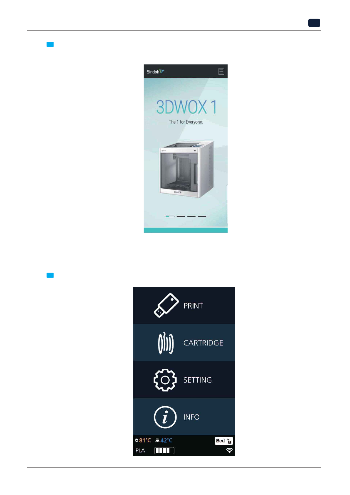
The website address is http://3dprinter.sindoh.com/
The 3dprinter homepage will be opened and user can view the information of user preference.
3
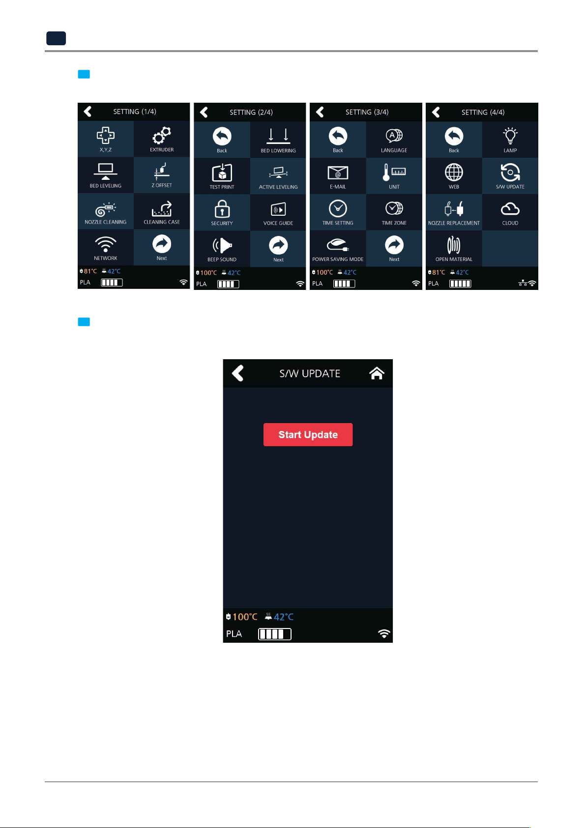
S/W UPDATE
With the printer connected to the internet user is able to download the latest software.
From the home screen, press [SETTING].
1
2-51
Page 86
UI Menu Function
2
updates will be applied.
Press [Next] 2 times and select [S/W UPDATE].
2
Press the [Start Update] button, and printer will start updating. After it has finished, restart the printer and
3
2-52
Page 87
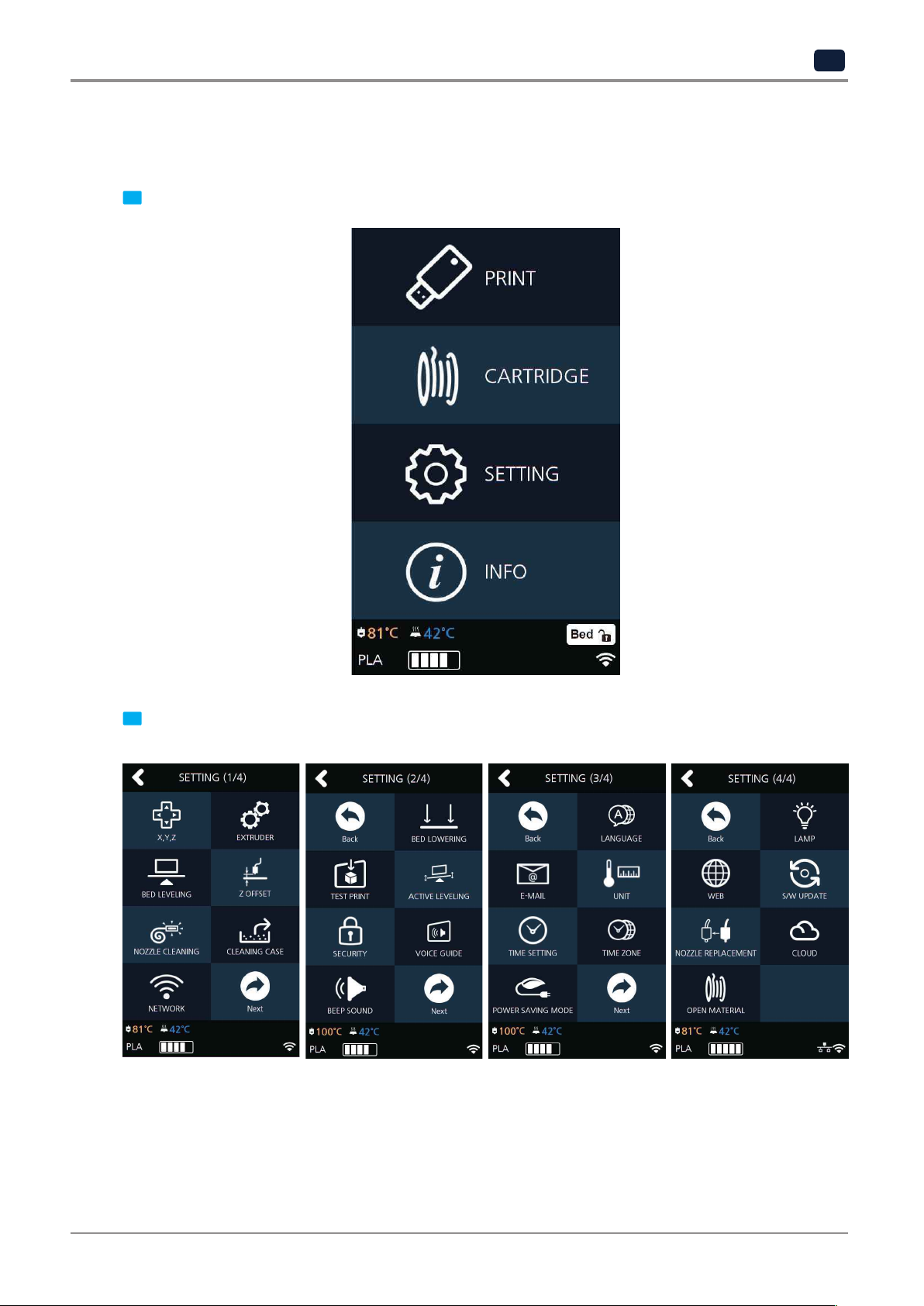
NOZZLE REPLACEMENT
This function is used to replace the nozzle of the machine.
From home screen press [SETTING].
1
UI Menu Function
2
Press [NOZZLE REPLACEMENT] to enter Nozzle Replacement settings.
2
2-53
Page 88
UI Menu Function
2
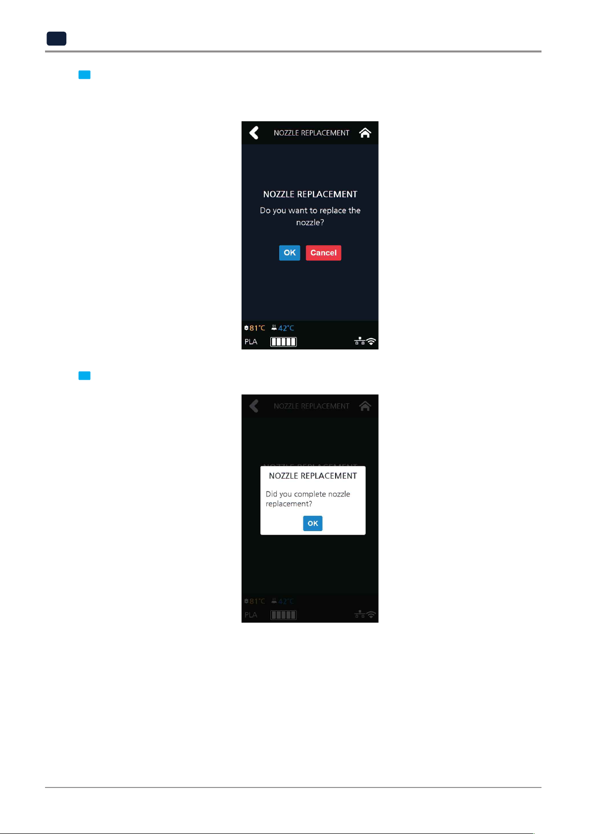
Press [OK] and perform nozzle replacement.
3
※Please proceed unload first.
Nozzle replacement is possible after the filament is unloaded. (See unload 2-5)
After completing nozzle replacement, press [OK].
4
2-54
Page 89
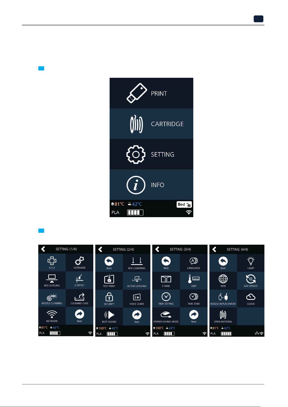
CLOUD
This menu enables you to set up the Cloud menu whether to use the 3D printer or not.
The machine will automatically reboot once the Cloud function setting is changed.
From the home screen, press [SETTING].
1
UI Menu Function
2
Press [Next] 3 times and select [CLOUD].
2
2-55
Page 90

UI Menu Function
2
Select whether to add or remove the function by using the arrow key and then press [OK] to save.
3
OPEN MATERIAL
The OPEN MATERIAL enables the usage of a third-party filament without any cartridge and smart chip.
In the cartridge mode, the filament is automatically loaded and unloaded in optimal conditions, with our
filament and smart chip.
On the other hand, the OPEN MATERIAL requires some manual operations by users for loading and unloading the
filament.
Instead, it has the advantage of being able to use a third-party filament.
T
Then, follow the UI guide to load the filament.
For “how to use the slicer in the OPEN MATERIAL,” refer to the slicer manual in the memory stick.
o use the OPEN MATERIAL, change the machine settings in the following procedure.
Press the [SETTING] button on the Home screen to access settings.
1
2-56
Page 91

UI Menu Function
2
Press the [Next] button to access the [OPEN MATERIAL] screen.
2
Press the arrow to change it to “Done” state and then press the [OK] button.
3
2-57
Page 92

UI Menu Function
2
Read the OPEN MATERIAL guide pop-up and then press the [OK] button.
4
Therefore, it is important to create a correct gcode and apply it to a device by fully understanding
the characteristics of a third-party filament, including the recommended printing temperature and speed.
not applicable.
A filament containing abrasive additives (metal component, carbon fiber) may cause transfer problem
and reduce the service life of nozzles.
Make sure that the spool to be used has the width of 67 mm or less and an outer diameter of 213 mm
or less.
this tends to cause the filament feeding problem (EC 401). If EC401 occurs, in order to continue printing,
please load new filament spool after unloading the left-over filament previously used in the machine.
Caution
-
Improper usage of a third-party filament may cause device failure and poor printing quality.
-
As soft filament with shore hardness of 65 D or less (TPU, TPE, etc.) may cause transfer problem, it is
-
If a third-party filament has a too large spool, it would not be usable with it inserted.
-
When 3rd Party Filament gets all consumed, the filament end sometimes gets stuck in the machine and
2-58
Page 93

UI Menu Function
2
“OPEN MATERIAL” is displayed at the bottom of the main screen.
5
Although the supports open material mode, we recommend the use of Sindoh filament on the printer.
The filament available for use in Open Material Mode is shown below.
Filament Bed Preparation
Recommended
Nozzle Temp(℃)
Recommended
Bed Temp(℃)
PLA N/A 200 60 Sindoh / 3
ABS N/A 230 90 Sindoh / 3
FLEX N/A 240 60 Sindoh / 3
rd
PETG N/A 230-250 80 3
ASA N/A 235-255 110 3
party
rd
party
Remark
rd
party
rd
party
rd
party
2-59
Page 94

UI Menu Function
2
1.3 Information
INFORMATION NAME
CHANGE NAME & PW
MODEL NAME
SERIAL NO.
VERSION
GUI VER.
WIRED IP
WIRED MAC IP
WIRELESS IP
WIRELESS MAC IP
WEB SITE
GUIDE
HISTORY
In this menu user is able to view the detail information of the printer, and set device name & password.
In [HIST
ORY] screen, user is able to view all the records of past works.
From home screen, press [INFO].
1
2-60
Page 95

UI Menu Function
2
To set password and name for printer, select [Change Name & PW].
2
By entering the password, you can edit name and set a new password. Pressing [OK] saves the changes.
3
Reference
-
*Initial password is ‘0000’.
2-61
Page 96
UI Menu Function
2
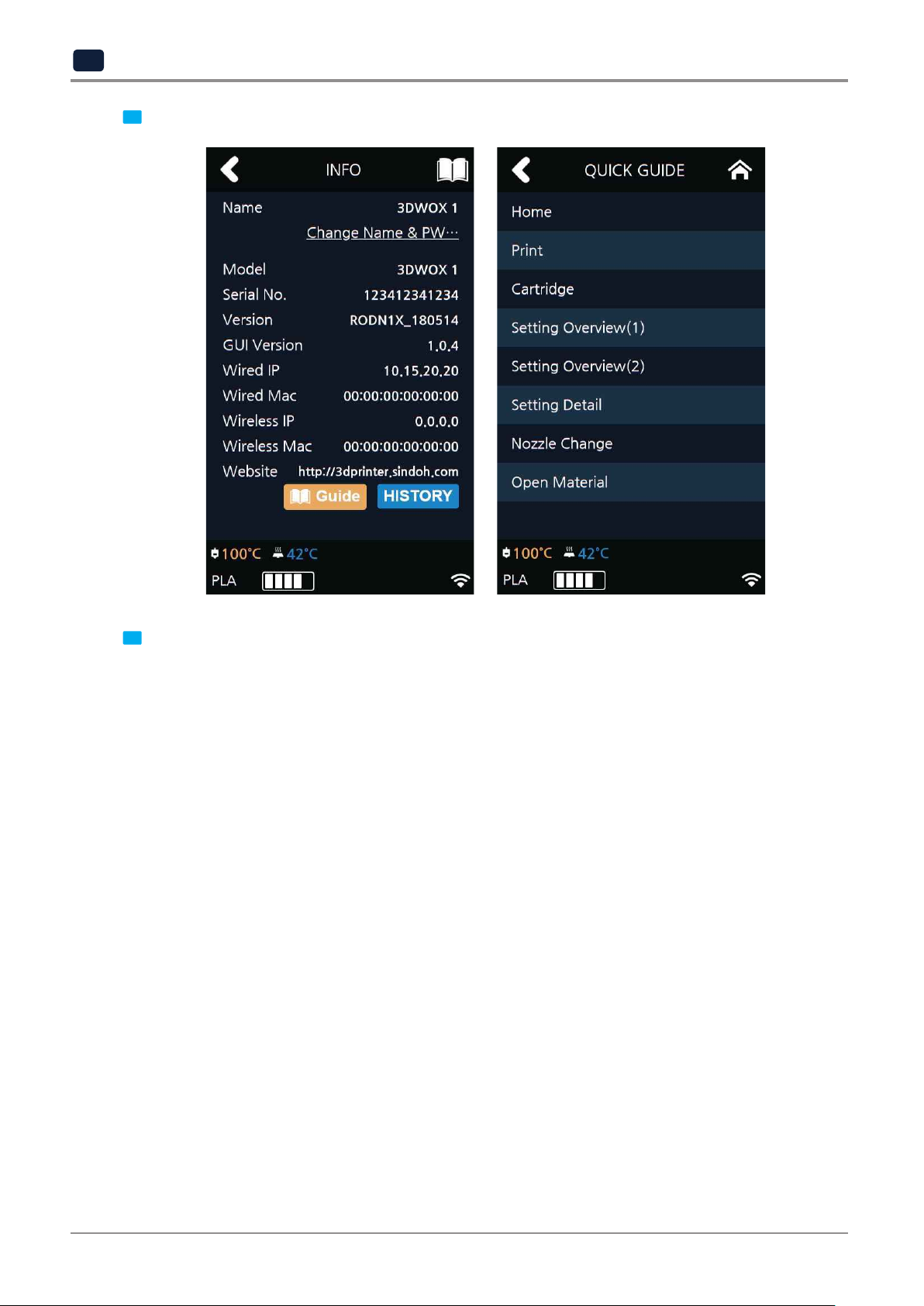
In [INFO] screen, press [Guide] to access to the "Quick Guide" for the printer.
4
device and the model serial number.
In addition, the [Info] screen allows you to view various other information such as the model name of the
5
2-62
 Loading...