

Page 1

M A N U A L
Simrad CP44/54
Chartplotter
183-3402-102 English 03101.10
Note!
Insert or remove C-MAP cartridges ONLY through SETUP menu or when
unit is off. All electronic navigation equipment is subject to external factors
beyond the control of the manufacturer. Therefore such equipment must be
regarded as an aid to navigation. The prudent navigator will, for that reason,
never rely on a single source for position fixing and navigation.
Page 2
MOB ‘MAN OVERBOARD’ function
MOB
In case someone falls overboard, press the [MOB] key and hold for 2
seconds (or activate an external MOB switch - hold for 5 seconds).
CLR
Press [CLR] to confirm and reset the alarm if activated by mistake.
Before pressing [ENT] to start MOB navigation:
• Reduce speed.
• Turn off Autopilot.
ENT
Press [ENT] to start MOB navigation with all relevant data available
for an efficient rescue operation and a precise track record of the
vesels movements.
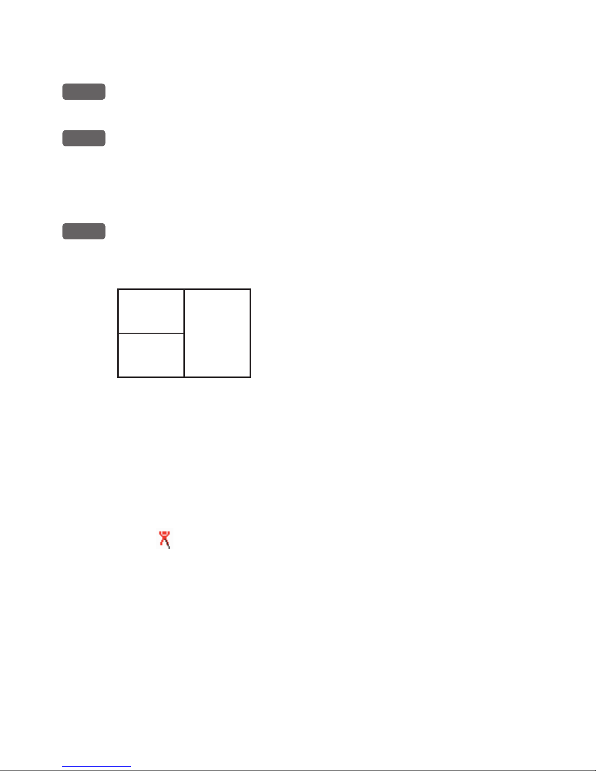
Window
1
Window
2
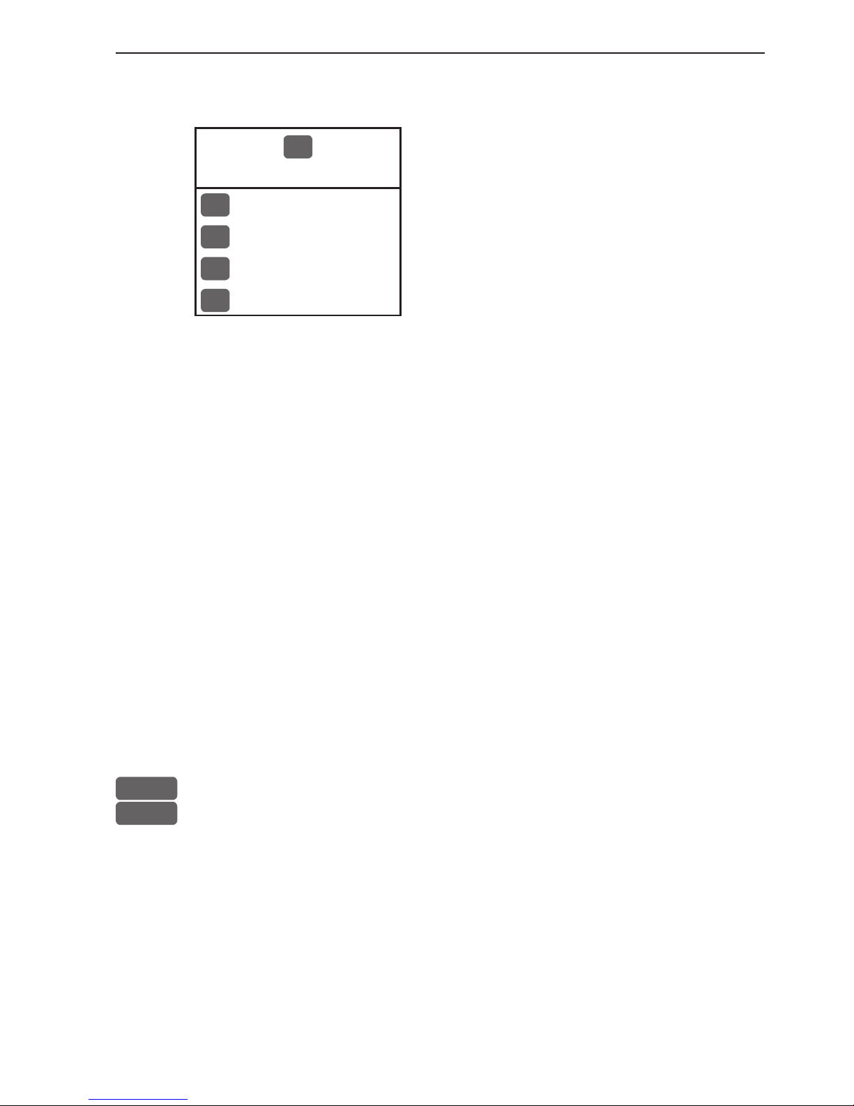
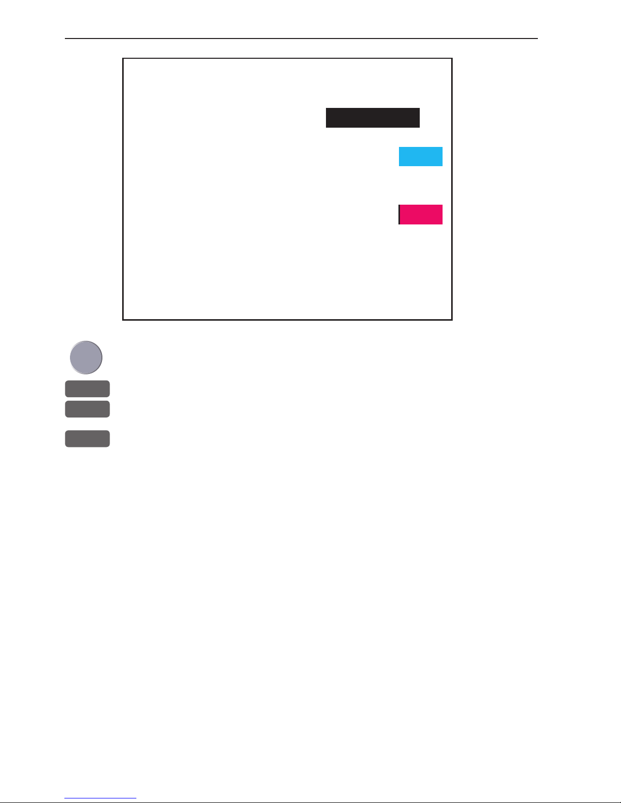
Screen layout default after activating MOB.
Window
3
Window 1: Data display will provide information of: Course, Bear-
ing and Distance to MOB position, time elapsed since the incident
occured - first in seconds and then in minutes - if “*” is shown
instead of numbers of minutes, means that the elapsed time has
exceeded 9999 minutes. The two lines after the TIME shows the
MOB position in Lat/Long.
Window 2: The chart display will provide a graphical impression of
a man
floating in the water at the MOB position together with a
course line from actual position to the incident.
Window 3: Data display will provide information of: Date, time and
position of MOB incident.
To turn MOB navigation off:
Press [GOTO], [3].
To recall the last registered MOB position, see section 7.8.
Page 3

CP44/54 Chartplotter Table of contents
MOB ‘MAN OVERBOARD’ function............................. back of front cover
Chapter 1 Introduction and safety summary
1.1 Introduction and system familiarization ...................................... 1-1
1.2 Safety summary ........................................................................... 1-2
1.3 How to get started ........................................................................ 1-3
1.3.1 Dedicated function keys............................................................... 1-3
1.3.2 Chart and chart functions............................................................. 1-5
Chapter 2 Fundamentals and initial start-up
2.1 Fundamentals of the display and page system ............................. 2-1
2.1.1 Example of how to exchange a page in the PAGE system ........... 2-2
2.1.2 Example of how to select a new display in a split screen............. 2-2
2.2 Key functions ............................................................................... 2-3
2.3 Menu bar....................................................................................... 2-5
2.4 Menu layout.................................................................................. 2-6
2.5 Choice of symbols ........................................................................ 2-7
2.6 Naming of routes, points etc......................................................... 2-7
2.7 Initial start-up............................................................................... 2-7
2.8 Turn power off.............................................................................. 2-8
Chapter 3 Chart menu and INFO windows
3. Chart menu ................................................................................... 3-1
3.1 Shortcut to the pages in the chart-series ...................................... 3-1
3.1.1 Data field on chart........................................................................ 3-2
3.1.2 Ship symbol .................................................................................. 3-3
3.1.3 Cursor function ............................................................................ 3-3
3.1.4 Range or zoom function ............................................................... 3-4
3.2 Dual Chart display........................................................................ 3-5
3.3 Chart custom screens ................................................................... 3-6
3.4 Chart quick menu ......................................................................... 3-7
3.4.1 Cursor inactive ............................................................................. 3-7
3.4.2 Cursor active but not placed on any object or data ......................3-8
3.4.3 Cursor placed on waypoint........................................................... 3-9
3.4.4 Cursor placed on route leg or line section.................................. 3-10
3.4.5 Cursor placed on routepoint or linepoint ....................................3-11
3.4.6 Cursor placed on trackpoint ....................................................... 3-12
3.4.7 Cursor placed on target .............................................................. 3-13
3.4.8 GOTO menu ................................................................................3-14
3.4.9 PLOT menu ................................................................................ 3-15
3.5 Chart setup ..................................................................................3-17
Page 4

Table of contents CP44/54 Chartplotter
3.5.1 Display modes in the chart setup ................................................3-18
3.5.2 Description of chart features...................................................... 3-20
Chapter 4 Echo menu
4. Echo menu.................................................................................... 4-1
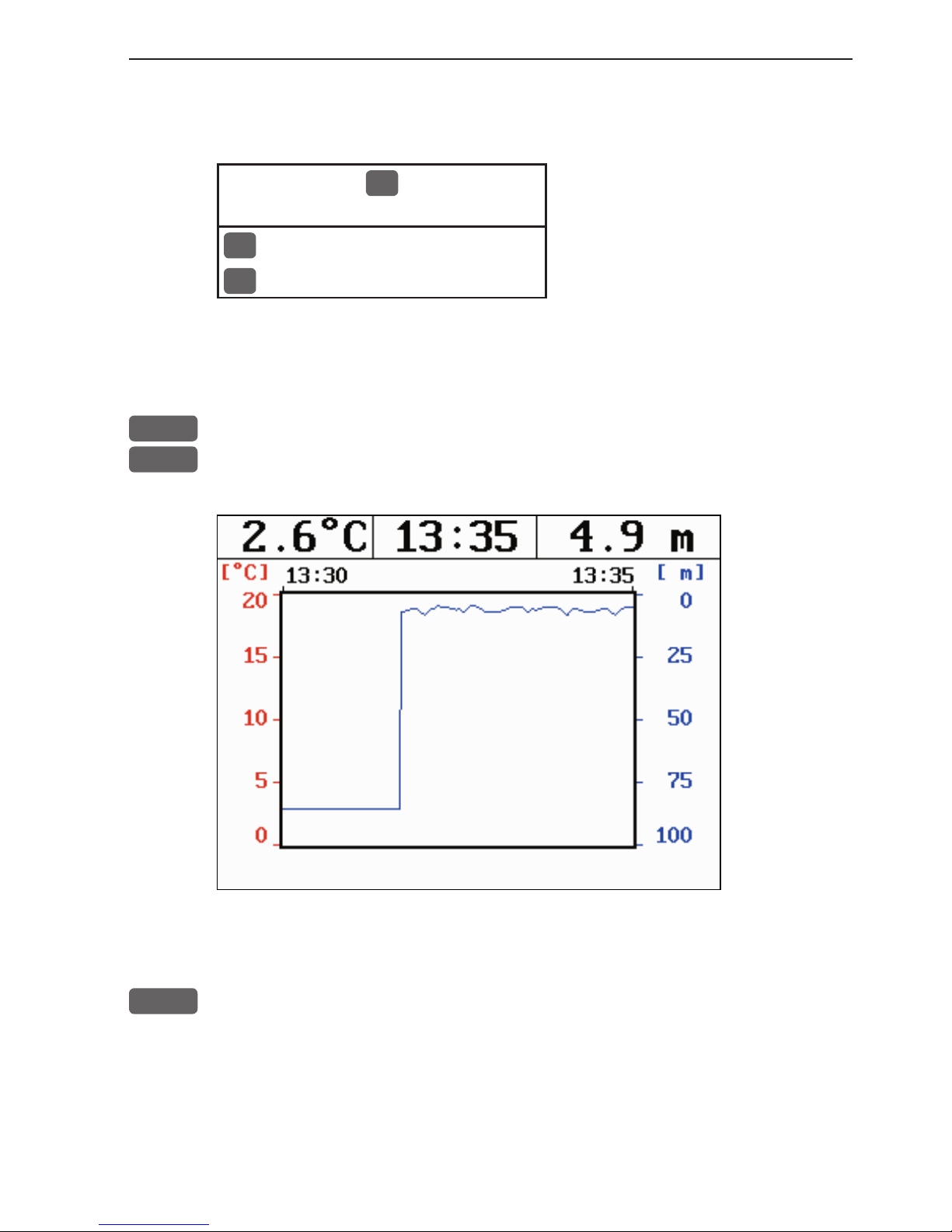
4.1 Depth & temperature diagram ..................................................... 4-1
4.2 Custom screen .............................................................................. 4-3
Chapter 5 Pilot menu & navigation examples
5. Pilot menu..................................................................................... 5-1
5.1 Shortcut to the pages in the pilot-series ....................................... 5-1
5.2 Highway display and Navigation setup ........................................ 5-3
5.2.1 Highway display when navigation mode is active........................ 5-5
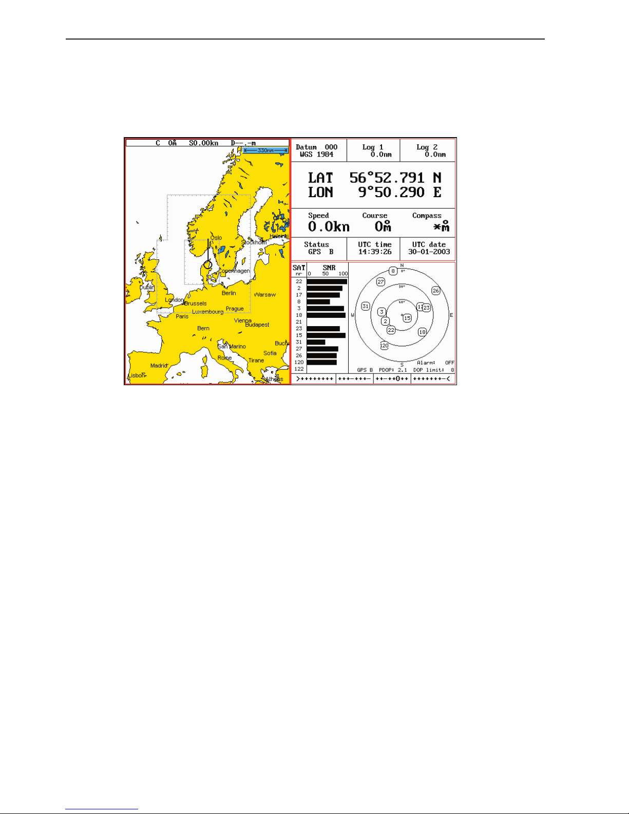
5.3 Position display............................................................................. 5-6
5.4 Dual speed display (trawling speed display)................................ 5-9
5.5 ETA & AVN display................................................................... 5-10
5.6 Trim & Highway display .............................................................5-11
5.7 Set & Drift display ..................................................................... 5-12
5.8 Pilot custom screens ................................................................... 5-13
5.9 Navigation examples ...................................................................5-14
5.9.1 Cursor navigation ........................................................................5-14
5.9.2 Waypoint navigation................................................................... 5-15
5.9.3 Route navigation..........................................................................5-16
5.9.4 Track navigation ..........................................................................5-17
5.10 Anchor guard.............................................................................. 5-19
5.11 MOB alarm and navigation ........................................................ 5-19
Chapter 6 Miscellaneous menu
6. Miscellaneous menu ..................................................................... 6-1
6.1 Wind display................................................................................. 6-1
6.2 Speed diagram.............................................................................. 6-3
6.3 Decca lanes................................................................................... 6-5
6.4 Loran C......................................................................................... 6-6
6.5 Satellite status............................................................................... 6-7
6.6 DGPS information........................................................................6-9
6.7 SDGPS information.................................................................... 6-11
6.7.1 Satellites in SDGPS system........................................................ 6-13
6.8 DSC info (feature prepared for future DSC VHF) .................... 6-14
Page 5

CP44/54 Chartplotter Table of contents
Chapter 7 Waypoint / route menu
7. Waypoint / route menu ................................................................. 7-1
7.1 Waypoints stored in the memory ................................................. 7-1
7.1.1 Delete waypoints via menu .......................................................... 7-2
7.2 Routes stored in the memory........................................................ 7-3
7.2.1 Delete route via menu................................................................... 7-6
7.2.2 Make new route from WP list ...................................................... 7-6
7.3 Route calculation .......................................................................... 7-8
7.4 Lines stored in the memory.......................................................... 7-9
7.4.1 Delete lines via menu ..................................................................7-10
7.5 Start / stop track ..........................................................................7-11
7.6 Tracks stored in the memory .......................................................7-12
7.6.1 Delete tracks via menu ................................................................7-13
7.7 Targets stored in the memory......................................................7-14
7.7.1 Delete target via menu.................................................................7-15
7.8 MOB data ....................................................................................7-15
7.9 Data transfer via DataCard or disc ..............................................7-16
7.9.1 List of criteria for data transfer in the Action column ................7-19
7.10 Data transfer via PC interface .................................................... 7-20
Chapter 8 Setup menu
8. Setup menu ................................................................................... 8-1
8.1 C-MAP cartridges ........................................................................ 8-1
8.2 Pilot / Position setup ..................................................................... 8-3
8.3 Speed alarm, units & language ....................................................8-4
8.4 Interface setup, NMEA ................................................................8-6
8.4.1 Default sentences.......................................................................... 8-7
8.4.2 Description of sentences...............................................................8-8
8.5 Interface setup, alarm/log output ............................................... 8-10
8.6 Palette setup.................................................................................8-11
8.7 Factory settings .......................................................................... 8-12
8.8 QuickGuide .................................................................................8-14
Chapter 9 Troubleshooting, Maintenance and Service
9.1 Troubleshooting............................................................................ 9-1
9.2 Preventive maintenance................................................................ 9-2
9.3 Repair and service ........................................................................ 9-2
9.4 Specifications ............................................................................... 9-3
Page 6

Table of contents CP44/54 Chartplotter
Appendix A Glossary of terms ...................................................................A-1
Appendix B List of datum ..........................................................................B-1
Appendix C C-MAP attributes...................................................................C-1
Index
Declarations of conformity
International warranty
List of Simrad distributors
Page 7

CP44/54 Introduction and safety summary Chapter 1-1
1.1 Introduction and system familiarization
Congratulations on your purchase of SIMRAD CP44/54 Chartplotter - a
combination of the latest GPS and SDGPS receiver technology and optional
built-in differential receiver for accurate positioning, plus: detailed cartography; all in a unique slim-line design with a bright 10” ATFT/TFT (CP44) or
15” TFT (CP54) color display.
The electronic chart system includes a built-in world chart for rough planning and overview. The choice of chart system best suitable for the CP44/54
was carefully singled out to be the C-MAP NT+ mini cards. The optional CMAP charts are available world-wide at your local Simrad dealer.
The Global Positioning System is at this time and age the most common
system used for navigation and positioning all over the world. Not only for
maritime use, but also for land-based applications and aviation. The satellitebased system has been developed and is operated by the US Department of
Defense in order to provide an accurate and reliable service, which include a
24-hour global coverage.
The GPS system consists of approx. 24 satellites which orbit around the Earth
at an altitude of approx. 20,200 km.
The satellites transmit perfectly synchronized data. However, depending on
the position, the signals will reach the receiver at a slightly different time. By
adding the measured time difference to the known position of the satellites it
is possible to calculate the ship’s position to within a few meters.
DS44/54 Dual Station for the CP44/54 is available with a bright 10” ATFT/
TFT or 15” TFT color display. The main unit and the dual station are identical
in design and operation.
How to use this manual? This manual is written for the products: CP44 and
CP54, which share the same type of software. From hereon, these models will
be referred to as: CPXX.
It is a good idea if you make yourself familiar with the key functions, menu
structure and rotation of pages (screens) described in chapter 2 before you
start out, and then proceed with section 2.7 Initial start-up. For quick location
of a certain term, please check the “Glossary of terms” and the “Index” at the
back of the manual. Also, “How to get started” further on in this chapter will
give you a quick introduction to some of the features you have access to in
your new chartplotter.
Page 8

Chapter 1-2 CP44/54 Introduction and safety summary
The display examples shown in this manual are not always an exact copy of
what you will see on the screen, as the presentation depends on your system
configuration and choices of setup.
How to interpret special marked key symbols etc. in the manual:
+/-
Either the + (plus) or - (minus) key may be applied.
0-9
Alpha-numeric keys for insertion of figures.
A-Z
Alpha-numeric keys for insertion of letters.
Emphasizes important points.
1,3
Indicates that you should press the keys [1] and [3] to obtain what is
written in italic next to the key.
1.2 Safety summary
Precaution: Do not open the equipment, only qualified persons should work
inside the equipment. If the glass in the screen breaks, be carefull not to get
cut on the sharp edges of the glass pieces.
The lifetime of the internal battery is minimum 5 years. If not exchanged
before it goes flat, all data in the unit’s memory will be lost. We strongly
recommend that you frequently store your data on a Simrad DataCard. For
exchange of battery, call your local Simrad workshop.
Power source, fuse and power cable: Check that the DC power supplied to
the unit is within the range of 10 to 32 volts. Note that the appropriate fuse
must be employed (see the fuse rating in section 9.4 Specifications). Ensure
that the power cord is firmly attached.
Grounding: To reduce electrical interference and risk of electrical shock,
properly ground the unit to the ship’s ground using the ground screw at the
rear of the unit. Good grounding should also be exercised for connected equipment, refer to separate Installation manual.
Cleaning:
Do not use any kind of strong solvents e.g. spirit, alcohol, gasoline or oils.
Page 9
CP44/54 Introduction and safety summary Chapter 1-3
1.3 How to get started
PWR
Press and hold the [PWR] key until you have a picture on the screen
PAGE
Press [PAGE] to scroll through a quick guide which informs of the
use of the keys and where you can enter owner’s setup
- the quick guide is also accessible via [MENU], [6], [6].
ENT
Press [ENT] when ready to assume normal operation
Your present position will automatically be updated within a few minutes. When
ready, the ship symbol on the chart will flash, the position coordinates will stop
flashing, and the *** will be replaced by actual course and speed figures.
1.3.1 Dedicated function keys
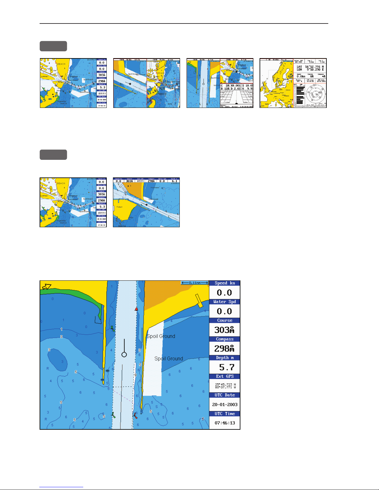
TRACK
Short press will activate:
➠
CHART
Short press will toggle between:
Chart + data field placed either at the right side or at the top.
CHART
Long press will toggle between:
Chart in full screen Dual Chart Custom screen1 Custom screen2
Page 10
Chapter 1-4 CP44/54 Introduction and safety summary
ECHO
Long press will toggle between:
Depth & temp. diagram Custom screen
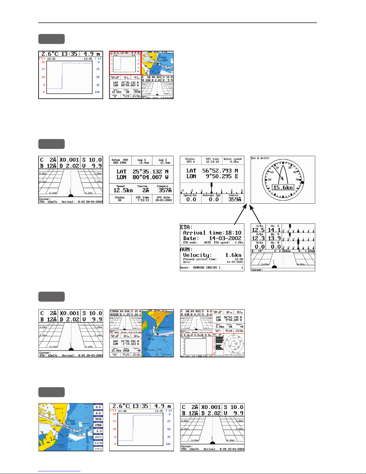
PILOT
Short press will toggle between:
Highway Position Dual Speed Set & Drift
When navigation mode is active,
these two displays will be included:
ETA & AVN Trim & Highway
PILOT
Long press will toggle between:
Highway Custom screen1 Custom screen2
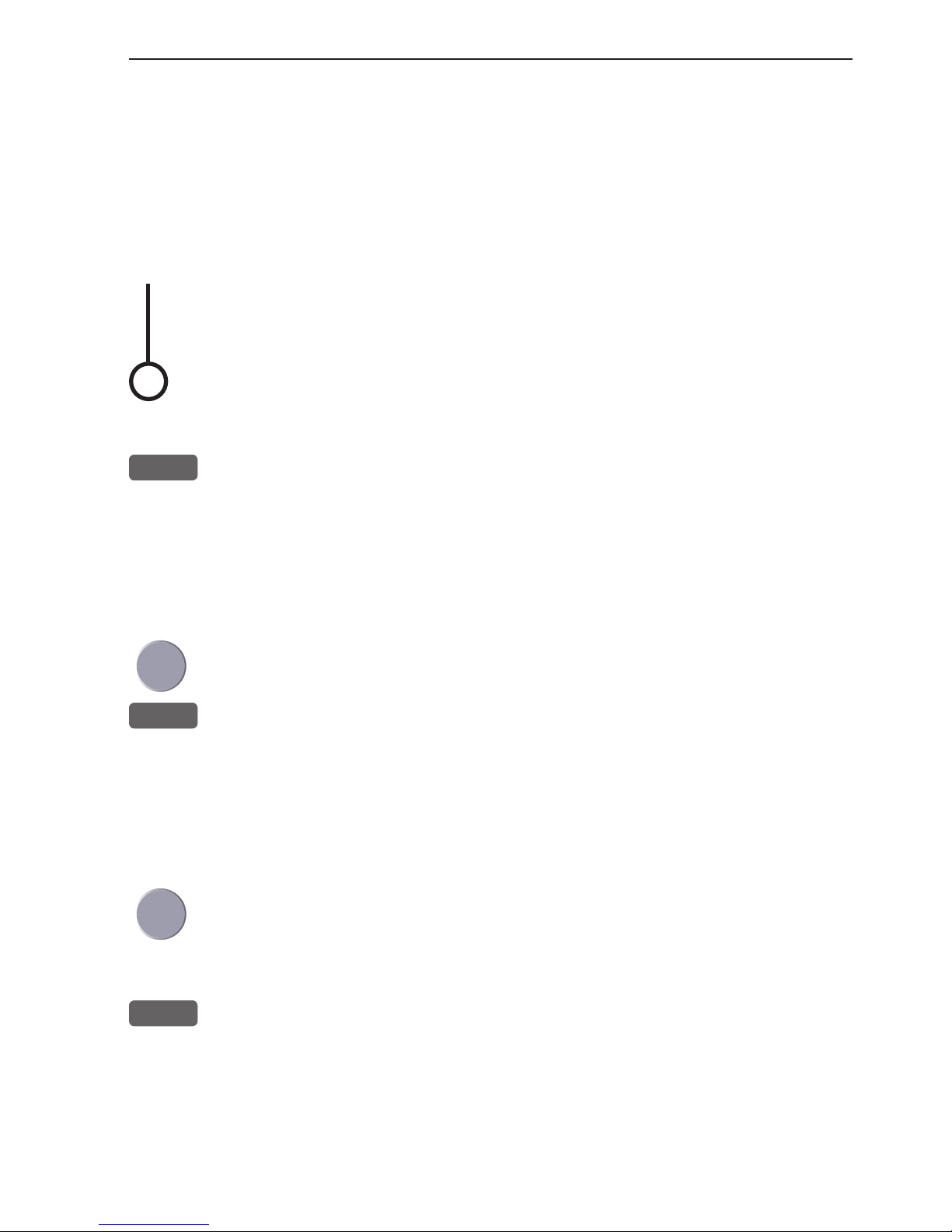
PAGE
Single press will toggle between the current active pages under the
main function
keys. Long press
will start a rotation
of the three pages
(section 2.1).
Page 11

CP44/54 Introduction and safety summary Chapter 1-5
1.3.2 Chart and chart functions
CHART
Press the [CHART] key to call up the chart display in full screen.
Press again to toggle between the chart shortcut series
- see chart examples in section 1.3.1.
C-MAP cartridges (standby)
Press [MENU], [6], [CHART] whenever inserting or removing a C-MAP card.
Select and adjust chart or echosounder range
Press one of the numeric keys 1 - 9 to select a range (and chart level).
Key 9 will select the largest range and key 1 the smallest. Use the +/- keys to
adjust range in smaller steps.
Chart cursor and info windows
Press the cursor key to activate the cross hair cursor on the chart. Place the
cursor on a C-MAP object e.g. a buoy or light to call up a small data window
with details on the object. The data window will stay on screen for about 10
seconds or till cursor is moved. Press [ENT], [2] to access further details on
C-MAP objects or user data i.e. waypoints, routes, etc.
Press [ENT], [5] to lock cursors in Dual Chart screen and [ENT], [5] to
release cursors again. Press [CLR] to switch off cursor function. The ship
symbol will now automatically ‘home’ and stay on screen.
Find nearest tide station and port services
1. Press [ENT], [3]
2. Move cursor up/down to select e.g. the Port/Marina symbol
3. Locate alternative port with the +/- keys, and press [ENT]
4. Press [ENT], [2] for more details on the facilities at the selected port.
Navigate to cursor (point and go)
1. Move the cursor to where you wish to go (first point)
2. Press [GOTO]
3. Press [1] to start navigation.
You can now move the cursor to the next point and when ready to change leg,
just press [GOTO], [2].
Page 12

Chapter 1-6 CP44/54 Introduction and safety summary
How to plot or insert waypoints and marks
• With cursor OFF (press [CLR])
Press [PLOT] and choose from:
[PLOT] Plot ship’s position as mark.
[1] Insert ship’s position. You can change the lat/lon figures, the symbol
and the symbol’s size and color.
[3] Insert specific waypoint. Suggested name, symbol, etc. can be altered.
[6] Plot ship’s position as target.
• With cursor activated on the chart you also have access to:
[2] Plot waypoint - cursor position.
[6] Plot cursor position as target.
How to make a route on the chart
1. Place the cursor on the position for the first routepoint.
2. Press [PLOT], [4]: Make route.
3. Move cursor to next destination and press [PLOT] - (repeat).
4. Press [ENT] when ready to save the route. You can enter a new name for the
route, change type and color for the course line.
5. Press [ENT] to accept and save the route.
How to make a route from existing waypoints stored in the WP list
1. Press [MENU], [5], [2] to call up the route list.
2. Press [CLR] Make new route from WP list.
3. Move cursor up/down to select the WP position for the first routepoint, and
press [PLOT].
4. Repeat point 3 to add new WP positions to the route (the last routepoint in
the right column is always empty, allowing that a new final routepoint can
be added later on).
5. When the route is completed, press [ENT] to accept and go to Edit route.
6. In the Edit route display, you can give the route a new name, change type
and color for the course line, etc.
7. Press [ENT] to accept changes and save the route.
8. Press [MENU] to go to the route list, which will provide an overall view of
the total of routes stored in the CPXX.
Page 13

CP44/54 Introduction and safety summary Chapter 1-7
How to edit a route - rubberbanding
• To move a point on the chart:
1. Place cursor on the point you wish to move.
2. Press [ENT], [1], [2].
3. Move cursor to new location.
4. Press [ENT] to complete.
• To insert a new point on the chart:
1. Place cursor on the leg where the new point is to be inserted.
2. Press [ENT], [1], [2].
3. Move cursor to where the new routepoint is to be placed.
4. Press [ENT] to complete.
How to start waypoint navigation (two ways)
• Place cursor on the symbol of the WP you wish to go to:
1. Press [GOTO], [2].
2. Press [ENT] to start navigation.
• Without placing cursor on the symbol of the WP you wish to go to:
1. Press [GOTO], [2].
2. Use the +/- keys to select the WP you wish to go to.
3. Press [ENT] to start navigation.
How to start route navigation (two ways)
• Place cursor on the routepoint you wish to go to first:
1. Press [GOTO], [3].
2. Select direction in route: Forward or Reverse.
3. Press [ENT] to start navigation.
• Without placing cursor on the routepoint you wish to go to first:
1. Press [GOTO], [3].
2. Use the +/- keys to select the name of the route.
3. Use the cursor to go to routepoint number, and select which one you wish to
go to first by means of the +/- keys.
4. Select direction in route: Forward or Reverse.
5. Press [ENT] to start navigation.
Page 14

Chapter 1-8 CP44/54 Introduction and safety summary
Advance or stop navigation
• Press [GOTO], [1] to advance to next point in the route.
• Press [GOTO], [3] to stop navigation.
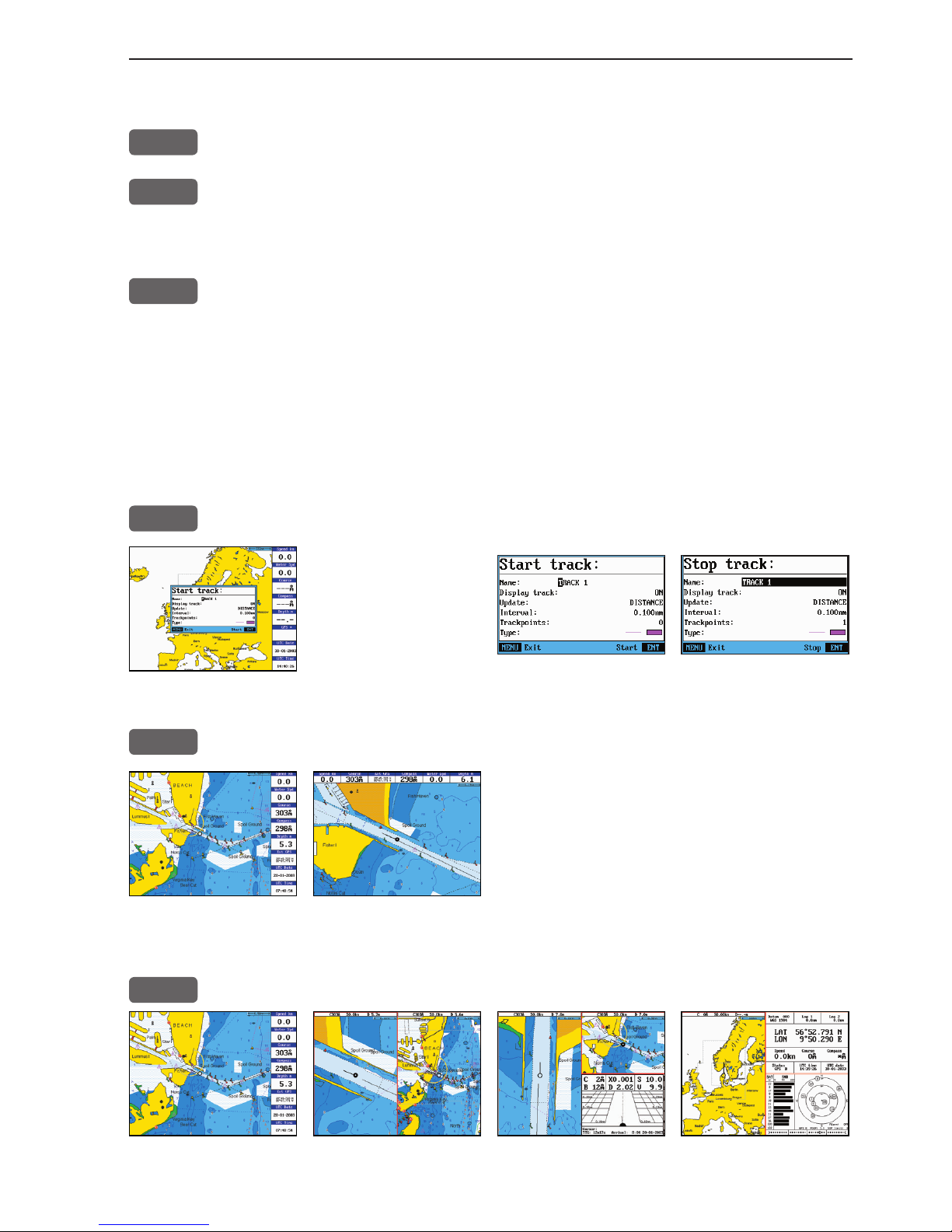
Start and stop track
1. Press [TRACK] to call up ‘Start track’ window.
2. Before tracking is started, you can give the track a new name, make
changes to track interval, track line type and color.
3. Press [ENT] to start track.
4. When you wish to stop tracking, press [TRACK], [ENT].
Page 15
Depth & temp-
erature diagram
Highway displayChart with
data field
CP44/54 Fundamentals & initial start-up Chapter 2-1
2.1 Fundamentals of the display and page system
The CP44/54 Chartplotter has a multi-function screen and data presentation system with full screen and different types of split screens.
The series of pages under the function keys (situated in the left
column of the keypad) will in most situations be sufficient information for the operator.
In split screens consisting of up to four displays, the active display
is indicated by a solid red frame. Use the [WIN] key to clockwise
toggle between which display on the screen is active. Only active
displays are operable.
The [PAGE] key differs from the other function keys. There are
three pages under the [PAGE] key which can be set up to the presentation you prefer by exchanging an existing display in the PAGE
system with a new one selected from a function key or via the menu
- see next page. Single press on the [PAGE] key will toggle between
the active pages under the function keys e.g.:
Page 16

Chapter 2-2 CP44/54 Fundamentals & initial start-up
Long press on the [PAGE] key will start a
rotation of the three pages in intervals of
5 seconds (increase/decrease the time in
[MENU], [6], [1]). Press any key to stop
rotation.
2.1.1 Example of how to exchange a page in the PAGE system
The three pages in the PAGE system are collected from the CHART,
ECHO and PILOT menus in the sequence of which the function keys
appear on the keypad ie. the first page is from the CHART function,
the second page is from the ECHO function and the third page is
from the PILOT function. This sequence can not be changed, only
the choice of display collected from each function can be changed
e.g.:
PAGE
Press the [PAGE] key until the full screen Chart display appears
MENU
Call up the menu bar, and...
2
collect the Dual Chart display
- or you can toggle between the available displays in the CHART
function by pressing (long press) the [CHART] key repeatedly.
The same applies for the other two pages in the PAGE system ie.
press the [PAGE] key until a display from the ECHO or PILOT
function appears and then collect a new display from the appropriate
menu.
The display sequence under the function keys is the same as the
display sequence in the matching menu.
2.1.2 Example of how to select a new display in a custom screen
In custom screens with multiple window combinations, all displays, which are not main function displays, are exchangeable. It is
also possible to change the right half of the screen from half screen
window to two quarter windows and vice versa. Example:
MENU
Call up the menu bar, and...
Page 17
CP44/54 Fundamentals & initial start-up Chapter 2-3
Highlight a function e.g. Route calculation in the WP/RTE menu.
WIN
Press [WIN] several times to check the screen image (situated to the
far right in the top line of the menu bar) which windows the function
can be placed into
ENT
Press [ENT] to enter the highlighted function into the highlighted
window
If the function text in the menu is red, the display will not be avail-
able for the selected window.
2.2 Key functions
Some of the key functions are general and can be applied at any
time, other key functions are related to a certain menu(s) and can
only be applied when in the appropriate menu.
MOB
Press for two seconds to activate the MOB - “Man overboard” function.
MENU
Turns the menu bar on/off. Exits any data display without taking any
action.
ENT
Confirms insertion and editing of data. Calls up information on
marks, waypoints, etc. on chart together with several INFO windows
from a chart display.
Moves cursor in data displays and charts + activates cursor on chart.
Moves left/right/up/down in the menu system.
+/-
Changes chart range i.e. + (plus) zooms out for better overview
(larger range) and - (minus) zooms in for greater chart details
(smaller range). Toggles between available values.
GOTO
Activates GOTO menu with choice of navigation modes, etc.
PLOT
Activates PLOT menu with choice of plotting and inserting way-
points, routes, lines etc. together with starting or stopping a track of
own ship.
TRACK
Shortcut to starting/stopping the track function.
Page 18

Chapter 2-4 CP44/54 Fundamentals & initial start-up
CHART
Shortcut to Chart function. Single press will toggle between differ-
ent data fields on chart. Long press will toggle between Chart in full
screen, Dual Chart, and two custom screens.
ECHO
Shortcut to Depth and temperature diagram, and a custom screen.
PILOT
Shortcut to Pilot displays. With navigation mode inactive: single
press will toggle between Highway, Position, Dual Speed and Set &
Drift displays. With navigation mode active: single press will toggle
between Highway, Position, Dual Speed, ETA & AVN, Trim &
Highway, and Set & Drift displays. Long press will toggle between
Pilot full screen and two custom screens.
PAGE
Toggles between active pages under the three main function keys i.e.
[CHART], [ECHO] and [PILOT]. Long press starts automatic rotation of these pages. Press any key to stop rotation.
ADJ
Gives access to setup displays related to active display.
A-B
Shortcut to the A-B function (with cursor active on chart display),
which provides bearing and distance from your current cursor position (A) to an arbitrary point (B).
WIN
Toggles between active windows in split screen. The active window
will have a solid red frame. Only active windows are operable.
0-9
The alphanumeric keys inserts and selects data in data displays.
Keys 1-9 are also Quick-range keys, which each represent a fixed
chart range. Key 0 will center the cursor/ship on the chart.
CLR
Turns cursor off in active display. Deletes data in enter or edit mode.
PWR
Power on - hold key depressed till you have a picture on the screen.
Calls up a window where you can adjust the brightness in the screen,
background light in keypad, and select Daylight displays, Night
display or custom made color palettes. Hold two seconds to turn the
power off.
Page 19
CP44/54 Fundamentals & initial start-up Chapter 2-5
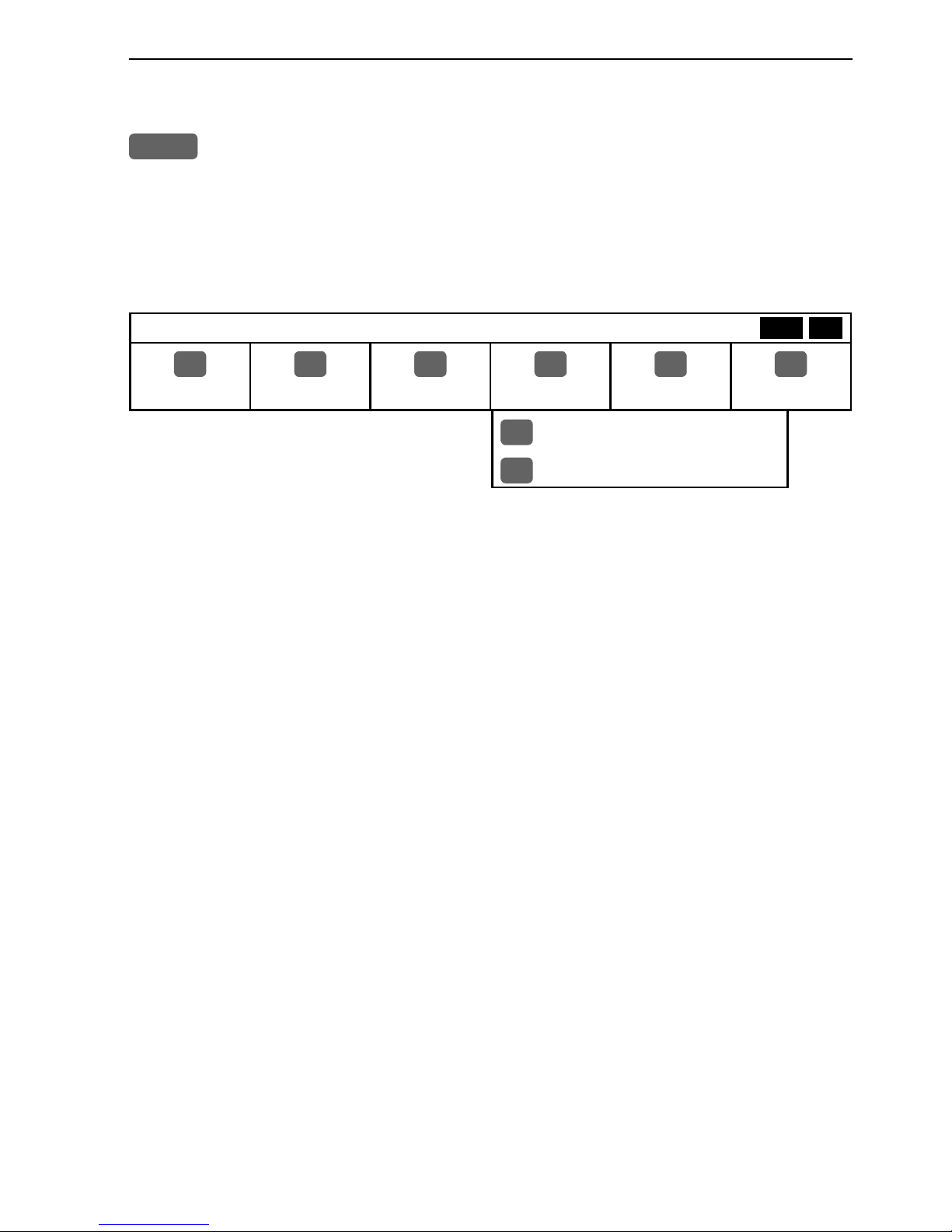
2.3 Menu bar
MENU
Toggle s the men u ba r on /of f
To fit the complete menu bar across the screen, some of the menus
have been abbreviated. However, the last selected menu will be highlighted, and if it’s an abbreviation of the menu, then the complete
menu title is written above the menu bar.
MISCELLANEOUS
1
CHART
2
ECHO
3
PILOT
4
MISC
5
WP/RTE
6
SETUP
1
Wind
2
Speed diagram, etc.
Having selected e.g. 4:MISC from the menu bar, its associated
menus will drop down. Key in the number next to the function you
wish to call forward, or use the cursor key to highlight the function
and press [ENT].
If you want to switch to a different menu, use the cursor key left/
right to move to the adjacent menu.
Most functions in the menus are general, and can be called forward
at any time. Functions not currently available will have a different
color from the rest of the functions. Not all functions are available
in any window size i.e. full screen, half screen or quarter window.
Use the [WIN] key to toggle between the windows in which the
highlighted function can be presented. Keep an eye on the functions
in the menu to see how they may change color as you toggle from
window to window.
The menu bar will disappear from the screen at the selection of a
function, or by pressing the [MENU] key. Besides, if not used, it
automatically turns off after 30 seconds.
WIN
Page 20
Chapter 2-6 CP44/54 Fundamentals & initial start-up
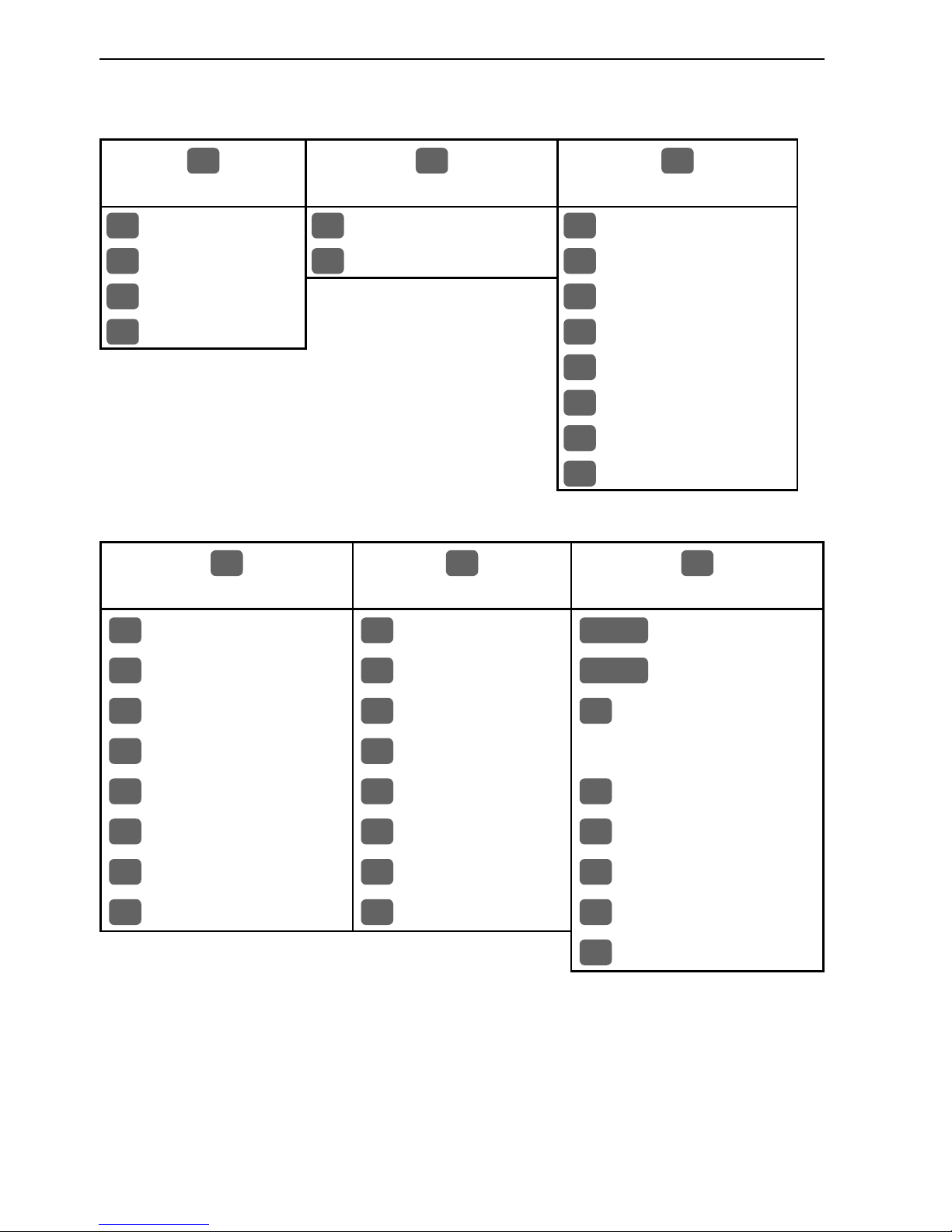
2.4 Menu layout
1
CHART
2
ECHO
3
PILOT
1
Chart
1
Depth & temp.diagram
1
Highway
2
Dual Chart
2
Custom screen
2
Position
3
Custom screen 1
3
Dual Speed
4
Custom screen 2
4
ETA & AVN
5
Trim & Highway
6
Set & Drift
7
Custom screen 1
8
Custom screen 2
4
MISC
5
WP/RTE
6
SETUP
1
Wind
1
Way points
CHART
C-MAP cartridge
2
Speed diagram
2
Routes
PILOT
Pilot/Position setup
3
Decca lanes
3
Route calculation
1
Speed alarm, units &
4
Loran C
4
Lines
language
5
Satellites
5
Tracks
2
NMEA interface
6
DGPS
6
Targets
3
Alarm/log output
7
SDGPS
7
MOB data
4
Palette setup
8
DSC info
8
Data transfer
5
Factory settings
6
QuickGuide
When selecting a sub-menu in the SETUP menu, the display will always
appear in a pop-up window, so once you have accepted the changes or decided
to just exit the display, then the display will disappear from the screen.
Page 21
CP44/54 Fundamentals & initial start-up Chapter 2-7
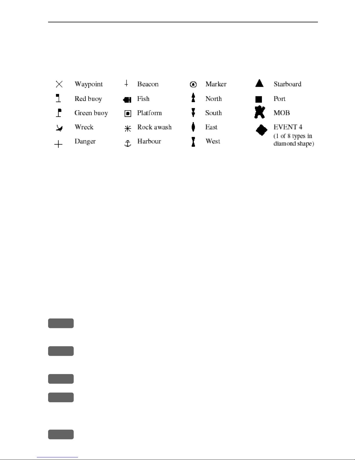
2.5 Choice of symbols
Waypoints and other points appearing on the screen can be marked by one of
18 symbols + 8 event marks in small or large symbols:
2.6 Naming of routes, points etc.
First select the key with the desired letter, then you can either repeat the
keystrokes, which will toggle between e.g. A,B,C,1, or once you have selected
one letter you can go back and forth in the alphabet by means of the +/- keys.
Use the cursor key to go to next space or to go back one space if you make a
mistake.
Depending on the selected language, the 0 (zero) key will hold special characters e.g. Æ Ø Å Ä Ö Ü Ñ, and the 9 (nine) key will hold: . - (empty space)
Press the [CLR] key to delete everything from cursor position and to the right
of cursor in that row.
2.7 Initial start-up
PWR
To turn on the CPXX, press and hold the [PWR] key till a picture
appears on the screen
PAGE
Press [PAGE] to scroll through a quick guide which informs of the
use of the keys and where you can enter owner’s setup
ENT
Press [ENT] when ready to assume normal operation
PWR
Press [PWR] again to adjust the lighting in the screen and select day
or night display etc., move around in display by means of the cursor
key and change settings with +/- keys, and...
ENT
Confirm with [ENT]
Page 22

Chapter 2-8 CP44/54 Fundamentals & initial start-up
The unit will now perform a fully automatic start-up and find the
correct position without further data entries. The start-up phase is
completed when the position coordinates stop flashing in the position display, meaning, the system now has a valid position - see
section 5.3.
Select display language:
MENU
Call up the menu bar, and...
6,1
press [6], [1] to call up the language display
Press up on the cursor to go to the bottom line in the display
+/-
Select language
ENT
Confirm entry
2.8 Turn power off
PWR
Call up INFO window, and...
PWR
Press and hold until screen turns black
The CPXX is now turned off. All the data and setups are saved and
stored in the internal memory and, of course, will be available next
time the unit is turned on.
Page 23
CP44/54 Chart menu and INFO windows Chapter 3-1
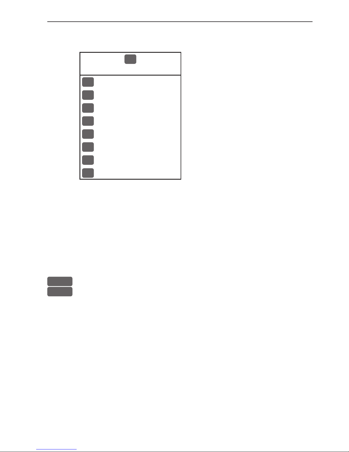
3. Chart menu
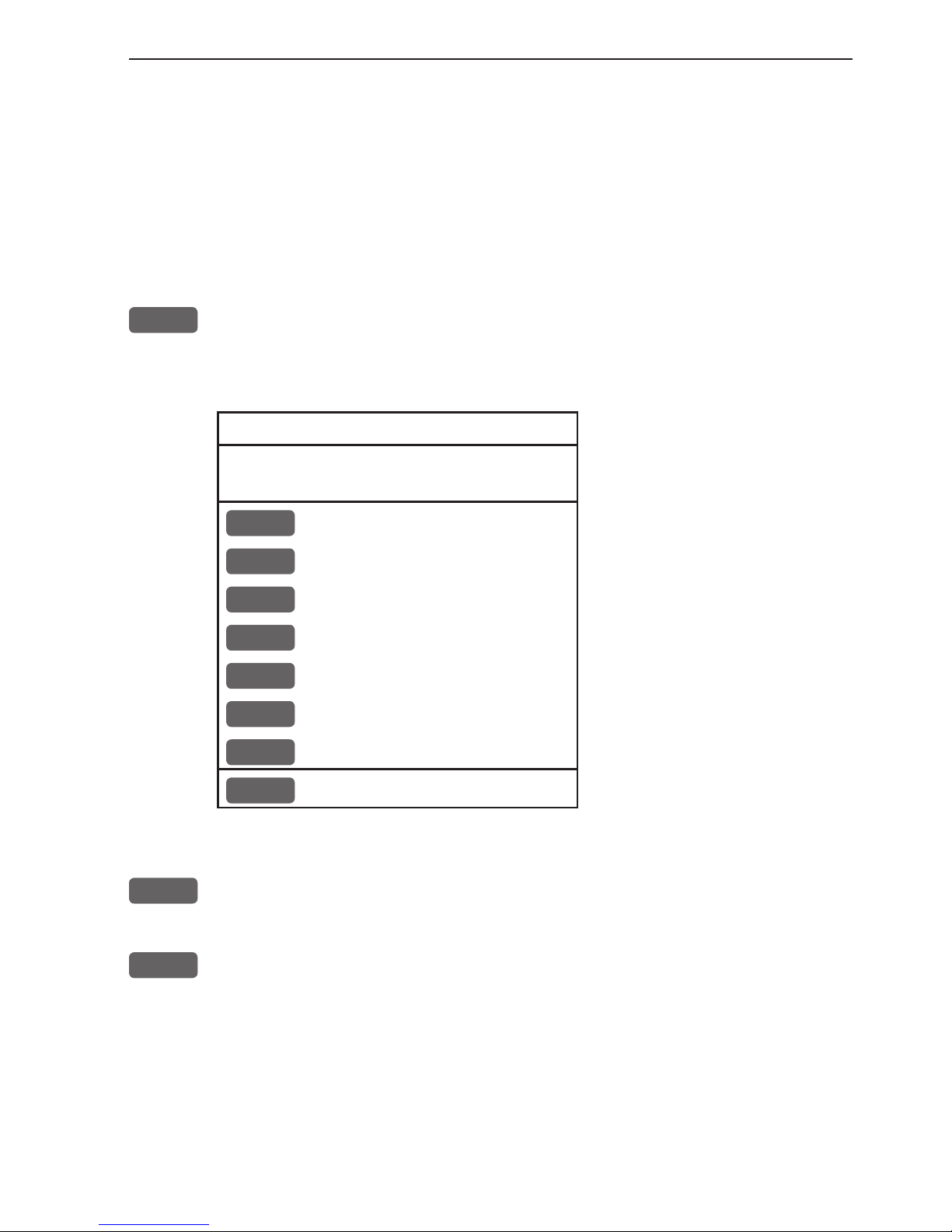
1
CHART
The displays obtained from this menu
can easily be accessed from the main
function key [CHART] see section 3.1.
1
Chart
2
Dual Chart
3
Custom screen 1
4
Custom screen 2
For safety reasons, navigation with electronic charts should always
be combined with authorized paper charts.
The chart display opens for the built-in world chart, as well as the
optional, detailed C-MAP electronic chart system, which of course
will require that a C-MAP NT+ C-card is inserted in one of the
drawers below the keypad. The chart appearing in full screen with
smaller range as default, is the only chart which can be inserted into
a different display via the menu.
The Dual Chart display will provide a chart in two different scales,
one for detail (smaller range) and one for overview (greater range).
The two custom screens will present multiple window combinations (section 3.1), where the chart with greater range as default will
be fixed in a quarter window. The chart with smaller range will be
fixed in the left half window in both custom screens. Adjustments
can be made individually to both charts (section 3.5).
To access one of the displays via the menu e.g.:
MENU
Call up the menu bar, and...
1,1
press [1] and [1] to call up a Chart in full screen
3.1 Shortcut to the pages in the chart-series
The CHART function is one of the main functions in the CPXX.
Each page under the [CHART] key will include a window representing the chart function. It is not possible to exchange main function
displays with a new display. Refer to section 2.1, 2.1.1 and 2.1.2 for
further information on the display and page system.
Page 24
Chapter 3-2 CP44/54 Chart menu and INFO windows
From any display:
CHART
Long press on the [CHART] key will toggle between:
Chart Dual Chart Custom screen 1 Custom screen 2
From full chart display:
CHART
Short press on the [CHART] key will toggle between different pres-
entations of the data field on the chart e.g.:
3.1.1 Data field on chart
Chart range indicator
(0.11nm) can be set
ON/OFF in ‘Show
range’ - section 3.5
Chart setup under
General.
During chart update/
redraw a progress bar
will cover the chart
radar indicator.
Depending on different situations, the data field on the chart display will give
you the ship’s current speed, speed through water, course, *position in lat/
Page 25
CP44/54 Chart menu and INFO windows Chapter 3-3
long, compass and depth indication, bearing and distance to either approaching point or cursor position; together with time and date in local or UTC.
*)Refer to section 5.3 Status indicator and accuracy.
3.1.2 Ship symbol
The ship symbol indicates the present position on the chart and the
vector informs of the actual heading (input from compass) or true
course (course over ground). There is a built-in autohome function
which automatically moves the chart to maintain the ship symbol in
the display (with cursor off).
0 ***
Press [0] to instantly center the ship on the chart (with cursor off).
3.1.3 Cursor function
With chart display active:
Press the cursor key to activate the chart cursor (cross hairs)
CLR
Press [CLR] to turn the chart cursor off
As default (section 3.5 Chart setup under General), the chart cursor
will automatically switch off if not used in the last five minutes. The
chart will update and bring the ship’s position to the center of the
screen.
Use the cursor key to move cursor in any direction on the screen
- the chart will automatically adjust when cursor reaches the edge of
the screen.
0 ***
Press [0] to instantly center the cursor on the chart (with cursor on).
In data displays the cursor will be shown in form of either a ruling
box around the active field, or the active field will be highlighted.
Page 26

Chapter 3-4 CP44/54 Chart menu and INFO windows
3.1.4 Range or zoom function
With chart display active:
1-9
Press one of the numeric keys to quickly change the chart scale:
[1] = 1:600 [2] = 1:2,000 [3] = 1:6,000
[4] = 1:20,000 [5] = 1:60,000 [6] = 1:200,000
[7] = 1:600,000 [8] = 1:2,000,000 [9] = 1:6,600,000
-
Press the minus key to zoom in for details (smaller range)
+
Press the plus key to zoom out for overview (greater range)
Using the extended level range will give the best result when changing chart range. First use one of the numeric keys (Quick-Range
1-9) to select the required chart, then ‘fine tune’ the range within
the same chart level by using the +/- keys. Depending on the actual
chart, you can zoom in or out two to three times before the extended
level range is switched off and the chart changes to a new level of
details.
The extended level range can be toggled OFF/ON in General settings
(default = OFF) - see section 3.5 Chart setup.
Chart details may not be available in all scales in all areas. Noncovered areas will be marked as hatched or all blue/white with
coordinate grid (when Grid is set to AUTO (default) in chart setup),
depending on the actual scale - see section 3.5 Chart setup for more
details in regard to what can be shown on the chart and what you
may choose not to have shown.
The built-in world chart can be zoomed up/down in six steps, from
a scale of approx. 1:33,000,000 to 1:2,000,000.
An over-zoom function enables you to zoom beyond the chart,
which automatically is switched off and replaced by a lat/long coordinate grid. In this mode, the scale can go down to 1:600.
‘Auto chart select’ must be switched OFF, see section 3.5 Chart
setup.
Page 27
CP44/54 Chart menu and INFO windows Chapter 3-5
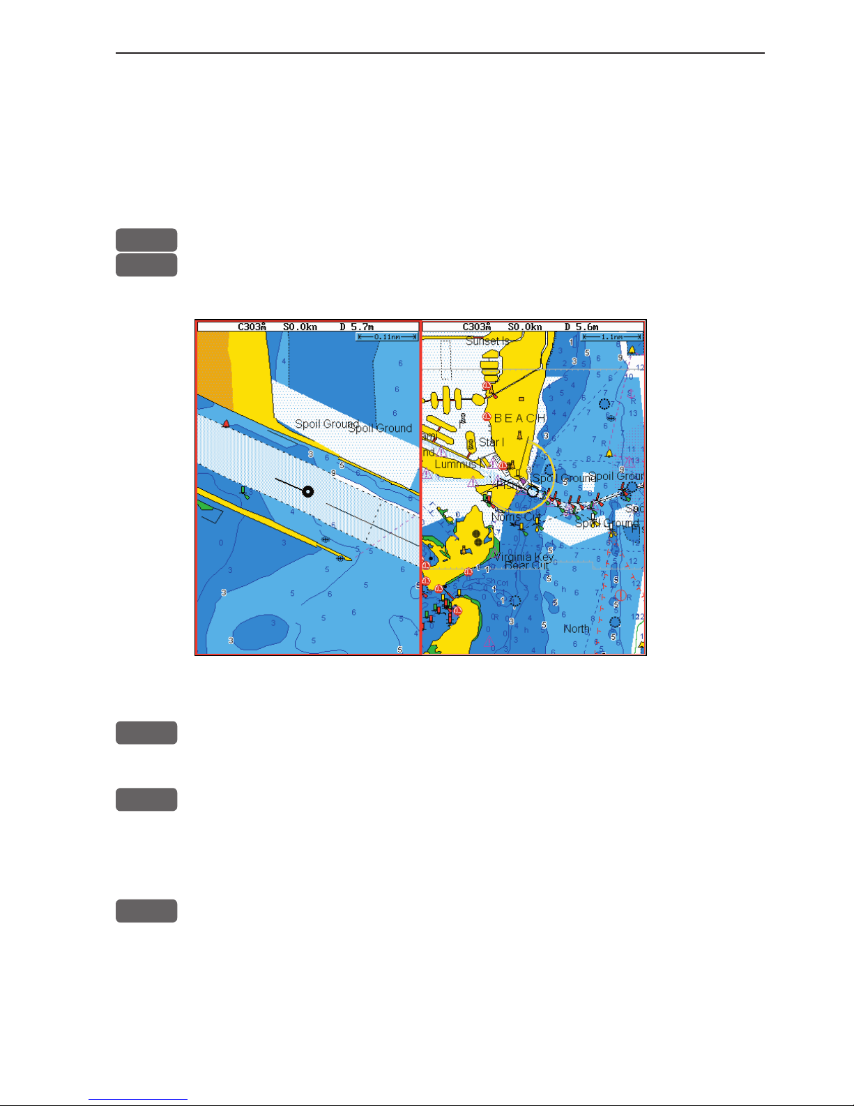
3.2 Dual Chart display
It is possible to have two charts in different scales on the screen at
the same time, one for detail and one for overview. Each chart can be
operated individually, and each will have its own cursor and individual chart setup.
MENU
Call up the menu bar, and...
1,2
press [1] and [2] to call up the Dual Chart display
WIN
Press the [WIN] key to select active display (red frame).
ENT
Press the [ENT] key to call up the chart’s Quick menu with access to
e.g. Chart info, Lock cursors to the same position in both charts on
the screen, etc. - refer to sections 3.4.2 for more details.
ADJ
Press the [ADJ] key to call up the chart setup for the active chart
- refer to section 3.5 for more details.
Page 28
Chapter 3-6 CP44/54 Chart menu and INFO windows
3.3 Chart custom screens
The two custom screens in the chart menu consist of multiple
window combinations e.g.:
The displays, which are not related to the chart function, can be
exchanged with a different one. It is also possible to change the right
half of the screen from two quarter windows to half screen window,
and vice versa. See section 2.1.2 how you go about changing the
displays.
Page 29
CP44/54 Chart menu and INFO windows Chapter 3-7
3.4 Chart quick menu
Access the chart quick menu from active chart display. The functions available depends on the actual situation - refer to sections 3.4.1
to 3.4.7.
3.4.1 Cursor inactive
ENT
With chart in active window, and with cursor off, press [ENT] to call
up the quick menu with the following to choose from:
Scale: 1:6600000 Actual chart scale
No user data
at ship’s position
1
Edit user data
Inactive function
2
Chart info
Refer to Appendix C
3
Find nearest port services
Refer to Appendix C
4
Bearing and dist from A to B
Inactive function
5
Lock cursors
Inactive function
0
Ship to center
PAGE
More user data
MENU
Exit
Exit info window
0
Ship to center will update the chart and place the ship’s position in
the center of the chart display.
PAGE
More user data will toggle between available data on the ship’s
position.
Page 30
Chapter 3-8 CP44/54 Chart menu and INFO windows
3.4.2 Cursor active but not placed on any object or data
ENT
With chart in active window, and cursor active but not placed on any
object or user data, press [ENT] to call up the quick menu with the
following to choose from:
Scale: 1:6600000 Actual chart scale
No user data
at cursor position
1
Edit user data
Inactive function
2
Chart info
Refer to Appendix C
3
Find nearest port services
Refer to Appendix C
4
Bearing and dist from A to B
5
Lock cursors
0
Cursor to center
PAGE
More user data
Inactive function
MENU
Exit
Exit info window
4
Bearing & dist. from A to B will quickly provide the bearing and
distance from your current cursor position (A) to an arbitrary point
(B). Move cursor to point B and see the calculation in the small info
window. Press [CLR] to exit the function.
5
Lock cursors will lock the cursors in two chart displays on the same
screen and thus make the cursor movements synchronized. To return
to individual cursor control in each chart display, press [ENT], [5] to
‘Release cursors’ again. See also ‘Lock cursors’ in Appendix A.
0
Cursor to center will update the chart and place the cursor position
in the center of the chart display.
Page 31

CP44/54 Chart menu and INFO windows Chapter 3-9
3.4.3 Cursor placed on waypoint
ENT
With chart in active window, and cursor placed on a waypoint, press
[ENT] to call up the quick menu with the following to choose from:
WP found
Name: WP 1
LAT 57°15.504N
LON 9°17.249E
1
Edit user data
2
Chart info
Refer to Appendix C
3
Find nearest port services
Refer to Appendix C
4
Bearing and dist from A to B
Refer to section 3.4.2
5
Lock cursors
Refer to section 3.4.3
0
Cursor to center
Refer to section 3.4.2
PAGE
More user data
MENU
Exit
Exit info window
1
Edit user data opens a new info window:
Waypoint
1
Edit
Edit name, symbol, color etc.
2
Move
Move waypoint with cursor
CLR
Delete
Delete waypoint
MENU
Exit
Exit info window
PAGE
More user data will toggle between available data on cursor’s posi-
tion
Page 32

Chapter 3-10 CP44/54 Chart menu and INFO windows
3.4.4 Cursor placed on route leg or line section
ENT
With chart in active window, and cursor placed on a route leg or line
section, press [ENT] to call up the quick menu with the following to
choose from:
Route leg found: 5-6
Name: RTE 1
Leg: B130° 34.26nm
Total: 5 legs 143.1nm
1
Edit user data
2
Chart info
Refer to Appendix C
3
Find nearest port services
Refer to Appendix C
4
Bearing and dist from A to B
Refer to section 3.4.2
5
Lock cursors
Refer to section 3.4.3
0
Cursor to center
Refer to section 3.4.2
PAGE
More user data
MENU
Exit
Exit info window
1
Edit user data opens a new info window:
Route leg
1
Edit leg
Open new info window to edit route leg
2
Insert point
Move cursor to insert new point
3
Edit
Open new info window to edit route
CLR
Delete
Delete the whole route
MENU
Exit
Exit info window
PAGE
More user data will toggle between data on routepoint and route
leg.
Page 33

CP44/54 Chart menu and INFO windows Chapter 3-11
3.4.5 Cursor placed on routepoint or linepoint
ENT
With chart in active window, and cursor placed on a routepoint or
linepoint, press [ENT] to call up the quick menu with the following
to choose from:
Routepoint found 5
Name: RTE 1
From start: 108.8nm
To end: 34.26nm
1
Edit user data
2
Chart info
Refer to Appendix C
3
Find nearest port services
Refer to Appendix C
4
Bearing and dist from A to B
Refer to section 3.4.2
5
Lock cursors
Refer to section 3.4.3
0
Cursor to center
Refer to section 3.4.2
PAGE
More user data
MENU
Exit
Exit info window
1
Edit user data opens a new info window:
Routepoint
1
Edit point
Open new info window to edit routepoint
2
Move point
Move point with cursor
CLR
Delete point
Delete routepoint
3
Add point
Add point to route - in beginning or at end.
4
Edit
Open new info window to edit route
5
Delete
Delete the whole route
MENU
Exit
Exit info window
PAGE
More user data will toggle between data on routepoint and route leg
Page 34

Chapter 3-12 CP44/54 Chart menu and INFO windows
3.4.6 Cursor placed on trackpoint
Trackpoints are not as easily recognized as Routepoints, you may
have to move the cursor along on the track to locate a trackpoint.
ENT
With chart in active window, and cursor placed on a trackpoint,
press [ENT] to call up the quick menu with the following to choose
from:
Trackpoint found 3
Name: TRACK 1
Total: 836 points
1
Edit user data
2
Chart info
Refer to Appendix C
3
Find nearest port services
Refer to Appendix C
4
Bearing and dist from A to B
Refer to section 3.4.2
5
Lock cursors
Refer to section 3.4.3
0
Cursor to center
Refer to section 3.4.2
PAGE
More user data
MENU
Exit
Exit info window
1
Edit user data opens a new info window:
Trackpoint
CLR
Delete point
Delete trackpoint
1
Delete points from A to B
See below
2
Edit
Open new info window
3
Delete
Delete the whole track
MENU
Exit
Exit info window
Press [1] to delete points from A to B - move cursor to point B, and
press [ENT] to delete all trackpoints between cursor position on
chart and point B.
PAGE
More user data if cursor is placed on a MOB track you can toggle
between data on MOB symbol and data on MOB track. The symbol
and track are edited separately.
Page 35

CP44/54 Chart menu and INFO windows Chapter 3-13
3.4.7 Cursor placed on target
ENT
With chart in active window, and cursor placed on a target symbol,
press [ENT] to call up the quick menu with the following to choose
from:
Target found
Name: TARGET 1
LAT 57°02.825N
LON 7°45.555E
1
Edit user data
2
Chart info
Refer to Appendix C
3
Find nearest port services
Refer to Appendix C
4
Bearing and dist from A to B
Refer to section 3.4.2
5
Lock cursors
Refer to section 3.4.3
0
Cursor to center
Refer to section 3.4.2
PAGE
More user data
MENU
Exit
Exit info window
1
Edit user data opens a new info window:
Target
1
Edit
Edit name, color, position etc.
2
Move
Move point with cursor
CLR
Delete
Delete target
MENU
Exit
Exit info window
PAGE
More user data will toggle between available data on cursor’s posi-
tion
Page 36
Chapter 3-14 CP44/54 Chart menu and INFO windows
3.4.8 GOTO menu
GOTO
Call up the GOTO menu with access to navigation modes:
Select NAV mode To select “Cursor” navigation will require
that the chart cursor is active.
“Waypoint”, “Route” and “Track” navigation requires that a waypoint, route or
track is stored in the memory.
1
Cursor
2
Waypoint
3
Route
4
Track
5
Anchor guard
MENU
Exit
For further details on the different NAV modes, refer to section 5.9
Navigation examples.
Anchor guard - when setting anchor, a pre-set alarm distance will
be activated, so in case the ship is drifting too far away from the
anchored position, the system will initiate a visual and acoustic alert
- refer to section 5.10 Anchor guard.
If pressing the [GOTO] key while one of the NAV modes is active,
this pop-up window will appear on the screen:
Navigation is ON
1
Advance
2
Restart to approaching point
3
Turn NAV OFF
MENU
Exit
Press [1] to advance to next waypoint in the route (Route navigation).
Press [2] if you for some reason have drifted off course and wish to
restart navigation from your actual position to the approaching point.
Page 37

CP44/54 Chart menu and INFO windows Chapter 3-15
3.4.9 PLOT menu
The CPXX is designed to make navigation easy and safe. Waypoints
can easily be plotted with a single keystroke, or be inserted via the
keypad. Making routes and drawing lines are done directly on the
chart. Very straightforward, uncomplicated and with a high level of
confidence as you can follow your actions ‘live’ on the chart.
PLOT
Call up the PLOT menu with the following to choose from:
PLOT new data
PLOT
Plot mark - ship
1
Insert mark - ship
2
Plot waypoint - cursor
3
Insert waypoint
4
Make route
5
Draw line
6
Plot target
7
Start track
8
Stop track
MENU
Exit
PLOT
From any display: Plot and save mark on ship’s position, including
actual depth indication. Preset name sequence: SHIP 1, SHIP 2 etc.
1
From any display: Plot and save waypoint. Ship’s position is sug-
gested, but you can key in a new position from keypad, change the
location name (cf.section 2.6), or change the symbol (cf.section 2.5)
and the color (select with +/- keys). Any changes made will be new
presets for plotting/insertion of ship’s position.
2
From active chart display with cursor on: Plot and save cursor posi-
tion as a waypoint. Preset name sequence: WP 1, WP 2 etc.
3
From any display: Plot and save waypoint. The position coordinates
are filled with zeroes, so you can key in the position you want from
the keypad, change the location name (cf.section 2.6), or change
the symbol (cf.section 2.5) and the color (select with +/- keys). Any
Page 38

Chapter 3-16 CP44/54 Chart menu and INFO windows
changes made will be new presets for plotting/insertion of the cursor
position.
- From active chart display with cursor on: Same options as above,
except that the zeroes in the position coordinates have been
exchanged with the cursor position.
4
From active chart display with cursor on: You can quickly make a
route by means of the cursor and the [PLOT] key. The present cursor
position will be the first position of the route you are about to make.
Move cursor to next position, and press [PLOT]. Continue in this
manner until the route is completed.
Existing waypoints can be used for making the route, simply by
placing the cursor on the waypoints and plot the positions. In case
you make a wrong plot, press [CLR] to erase the last plotted position. Save the route with [ENT] or exit the function with [MENU] to
abandon the route.
Do not use the exact position of buoys, markers etc. as waypoints
and routepoints. The high accuracy of the system may result in a collision when sailing in the dark or navigating with an autopilot.
5
From active chart display with cursor on: To draw lines or to make a
route is the same procedure, please see above.
6
From active chart display: With cursor on, plot target at cursor posi-
tion and with cursor off, plot target at ship’s position.
After plotting the target it will be saved in the memory, and you can
edit the target later on, either via the menu (cf.section 7.7) or directly
from the chart (cf.section 3.4.7).
7
From any display: Call up info window to start track. To change
default values, see section 7.5.
8
From any display: Call up info window to stop track.
Page 39

CP44/54 Chart menu and INFO windows Chapter 3-17
3.5 Chart setup
The settings are dedicated to the chart in the active window i.e smaller
range or greater range chart, and does not affect the other chart.
ADJ
Load chart setup related to active chart
Settings
Depth
Presentation
User data
Display mode FULL
Orientation NORTH UP
Rotation resolution 15°
Motion RELATIVE
Quick chart info ON
Cursor 5 min. time-limit ON
Auto chart select ON
Extended level range OFF
Show range WITH BACKGROUND
MENU
Exit
PAGE
Next Accept
ENT
The left column indicates which levels are available in each display
mode e.g. the above example shows that in FULL display mode you
can access the levels in black: General, Presentation and User data use the [PAGE] key to go to the next level. The two levels in grey i.e.
Settings and Depth are not available in this display mode.
See further on in this chapter for more details on the many features
in the chart setup.
Scroll up/down in all the chart settings in the right column
+/-
Toggle between available settings
ENT
Confirm changes and return to chart, or...
MENU
Abandon Chart setup and return to chart without making any
changes
General
Page 40

Chapter 3-18 CP44/54 Chart menu and INFO windows
3.5.1 Display modes in the chart setup
There are six different display modes to choose from: FULL (default),
CUSTOM, SIMPLE, FISHING, LOW and GRID. When a function or level is
shown in grey text it means that it is not available in the selected display mode.
The default settings in the various display modes are:
Level: General
The available functions are according to display example on previous page for
all display modes, except for GRID, which only offer two functions:
Motion = RELATIVE
Cursor 5 min. time-limit = ON
Show range = WITH BACKGROUND
Level: Settings
The default settings in this level are fixed in all display modes, except for
*Custom where it is possible by the user to turn a feature ON (shown on the
chart) or OFF (not shown on the chart), etc.
These C-MAP features are not available in GRID display mode.
C-MAP features
Full *Custom Simple Fishing Low
Marine:
Names
Nav-Aids
Light Sectors
Attention Areas
Tides, currents
Nature of seabed
Ports
Tracks, routes
Buoys
Signals
Land:
Natural features rivers
Natural features
Cultural features
Landmarks
Chart:
Grid
Boundary lines
Mixing levels
Declutter
ON
INT
ON
ON
ON
ON
ON
ON
ON
ON
ON
ON
ON
ON
AUTO
AUTO
ON
ON
ON
INT
ON
ON
ON
ON
ON
ON
ON
ON
ON
ON
ON
ON
AUTO
AUTO
OFF
ON
ON
INT
OFF
ON
ON
OFF
ON
OFF
ON
ON
ON
OFF
OFF
ON
AUTO
AUTO
OFF
ON
ON
INT
OFF
ON
OFF
ON
OFF
OFF
ON
ON
OFF
OFF
OFF
OFF
AUTO
OFF
ON
ON
OFF
INT
OFF
OFF
OFF
OFF
OFF
OFF
OFF
OFF
OFF
OFF
OFF
OFF
AUTO
OFF
OFF
ON
Page 41

CP44/54 Chart menu and INFO windows Chapter 3-19
Level: Depth
The default settings in this level are fixed in all display modes, except for
*Custom where it is possible by the user to alter the features.
These C-MAP features are not available in GRID display mode.
C-MAP features
Full *Custom Simple Fishing Low
Soundings
Underwater objects
Depth Lines
Depth Lines>
Depth Lines<
Depth Areas
Depth
Level 1
Level 2
Level 3
ON
ON
ON
0000m
9999m
ON
0-002m
2-009m
9-MAX
ON
ON
ON
0000m
9999m
ON
0-002m
2-009m
9-MAX
ON
ON
ON
0000m
5m
ON
0-002m
2-009m
9-MAX
ON
ON
ON
0000m
9999m
ON
0-002m
2-009m
9-MAX
OFF
ON
OFF
0000m
5m
OFF
0-002m
2-009m
9-MAX
Level: Presentation
The default settings in this level are the same for all display modes, except
GRID, which do not include C-MAP features. The features can be changed
from FILLED to CONTOUR in all the display modes mentioned below.
C-MAP features
Full Custom Simple Fishing Low
Land areas
Depth areas
Caution areas
Dredged areas
FILLED
FILLED
FILLED
FILLED
FILLED
FILLED
FILLED
FILLED
FILLED
FILLED
FILLED
FILLED
FILLED
FILLED
FILLED
FILLED
FILLED
FILLED
FILLED
FILLED
Page 42

Chapter 3-20 CP44/54 Chart menu and INFO windows
Level: User data
The default settings in this level are the same for all display modes and any
change of the default settings can be carried out individually in all display
modes.
Chart features Defaults and choice of settings
Waypoints
Non active waypoints ON
Waypoint names ON
Waypoint depths ON
Routes
Non active routes AS SELECTED
Route names ON
Tracks
Non active tracks AS SELECTED
Track names ON
Lines
Lines AS SELECTED
Line names ON
Targets
Targets AS SELECTED
Target names ON
All the features in the user data level
that are set as default to ON= shown
on chart, can be changed to OFF= not
shown on chart.
Non active routes and tracks, all lines
and all targets are default to:
AS SELECTED= the choices made
for a particular route etc via the menu
e.g. MENU, 5, 2, ENT, ENT - Edit
route, where ‘Course line’ can be set
ON or OFF.
‘AS SELECTED’ can also be changed
to ‘ALL ON’= shown on the chart,
or ‘ALL OFF’= not shown on the
chart.
3.5.2 Description of chart features
Auto chart select - When sailing with ‘Auto chart select’ ON and cursor
turned off, the range will automatically change to match the chart which is
available. But when set to OFF, then the selected range will remain, also when
sailing ‘out of the chart’.
Boundary lines - will indicate available C-MAP chart areas.
Caution areas - can be set to FILLED or CONTOUR.
FILLED= The caution areas will be filled with a preset color from C-MAP.
CONTOUR= The caution areas will be shown with a contour line only and the
fill will be the same as the background/water color on the chart.
Page 43

CP44/54 Chart menu and INFO windows Chapter 3-21
Cursor 5 min. time-limit - can be set ON or OFF. When set to ON, the chart
cursor will automatically turn off if not used in a period of five minutes.
Declutter - when set to ON there will be no overlapping text on the chart e.g.
Names, Spot soundings etc.
Depth: Level 1, 2 and 3 - are identified by different colors. The number of
meters in the levels can be changed. The colors are preset in the Palette setup.
Depth areas - can be set ON or OFF= Not shown on chart.
FILLED - the depth areas will be filled with the color preset in the Palette
setup.
CONTOUR - the depth areas will be marked by a contour line only, and the
fill will be the same as the background/water color on the chart.
Depth lines - can be set ON or OFF= Not shown on chart.
Dredged areas - can be set to FILLED or CONTOUR.
FILLED= The dredged areas will be filled with a preset color from C-MAP.
CONTOUR= The dredged areas will be shown with a contour line only, and
the fill will be the same as the background/water color on the chart.
Extended level range - will enable changing range 3-4 steps within the same
chart level after having selected the range via a numeric key.
Grid - the LAT/LON grid can be set to ON or AUTO
ON= The LAT/LON grid will be visible on the chart display all the time.
AUTO= The LAT/LON grid will appear on the chart display when there is no
actual chart available in the selected scale.
The color of the grid is preset in the Palette setup.
Land areas - can be set to FILLED or CONTOUR.
FILLED= The land areas will be filled with a preset color in the Palette setup.
CONTOUR= The land areas will be shown with a contour line only and the
landfill will be the same as the background/water color on the chart.
Land settings -
can all be set ON=Shown on chart or OFF=Not shown on chart.
Marine settings
- can all be set ON or OFF, except for Nav-Aids which can be
set to INTERNATIONAL, INT. SIMPLIFIED, US, US SIMPLIFIED or OFF.
INTERNATIONAL - will present NavAids in ‘real life’ shapes and colors for
quick visual recognition (as per official INT1 standard paper chart presentation).
INT. SIMPLIFIED - the NavAids will be shown in generic symbols for minimum visual clutter on-screen.
Page 44

Chapter 3-22 CP44/54 Chart menu and INFO windows
US - will present NavAids in simplified shapes and real colors (as generally
found on NOAA paper charts).
US SIMPLIFIED - the NavAids will be shown in generic symbols for minimum visual clutter on-screen.
OFF - will shown no Nav-Aids on the chart.
Mixing levels - when set to ON, the number of blank chart areas will be
reduced, as the C-MAP library will find the missing area in a different level
to cover the blank area otherwise left on the screen. However, when using this
feature, chart re-draw time will be increased a little.
Orientation - can be set to NORTH UP, HEAD UP or NAV UP, and the mode
can be RELATIVE or TRUE motion.
NORTH UP - the chart will always be presented as north up.
HEAD UP - the chart will automatically turn, so your actual course (COG)
is up. If chart cursor is active it will stop the chart from rotating, press [CLR]
to turn cursor off. If a compass is connected, the reference will automatically
change to heading (compass).
NAV UP - the chart will automatically turn, so your bearing to destination is
up. If chart cursor is active it will stop the chart from rotating, press [CLR] to
turn cursor off.
RELATIVE motion - the ‘ship is positioned at the center of the screen and the
chart will move.
TRUE motion - the ‘ship’ will move across the chart.
Quick chart info - placing the chart cursor on a C-MAP object will activate a
small info window with details on the object. Info window will automatically
close after 10 seconds or when cursor is moved away.
Rotation resolution - can be set to adjust the chart for each 5, 10, 15, 20 or
25° changes in relation to present course or heading.
Show range - can be set to WITH BACKGROUND, ON or OFF:
WITH BACKGROUND - will add a small line to the chart display indicating
that the length of the line equals a certain number of nautical miles/km - the
indication is highlighted with a background color.
ON - same as above, but without background color.
OFF - indication is not shown on chart.
Soundings -
can be set to ON or OFF.
ON - the information will be shown as selected i.e. in feet, fathoms or meters.
OFF - soundings are not shown on chart.
Underwater objects - can be set ON or OFF= Not shown on chart.
Page 45
CP44/54 Echo menu Chapter 4-1
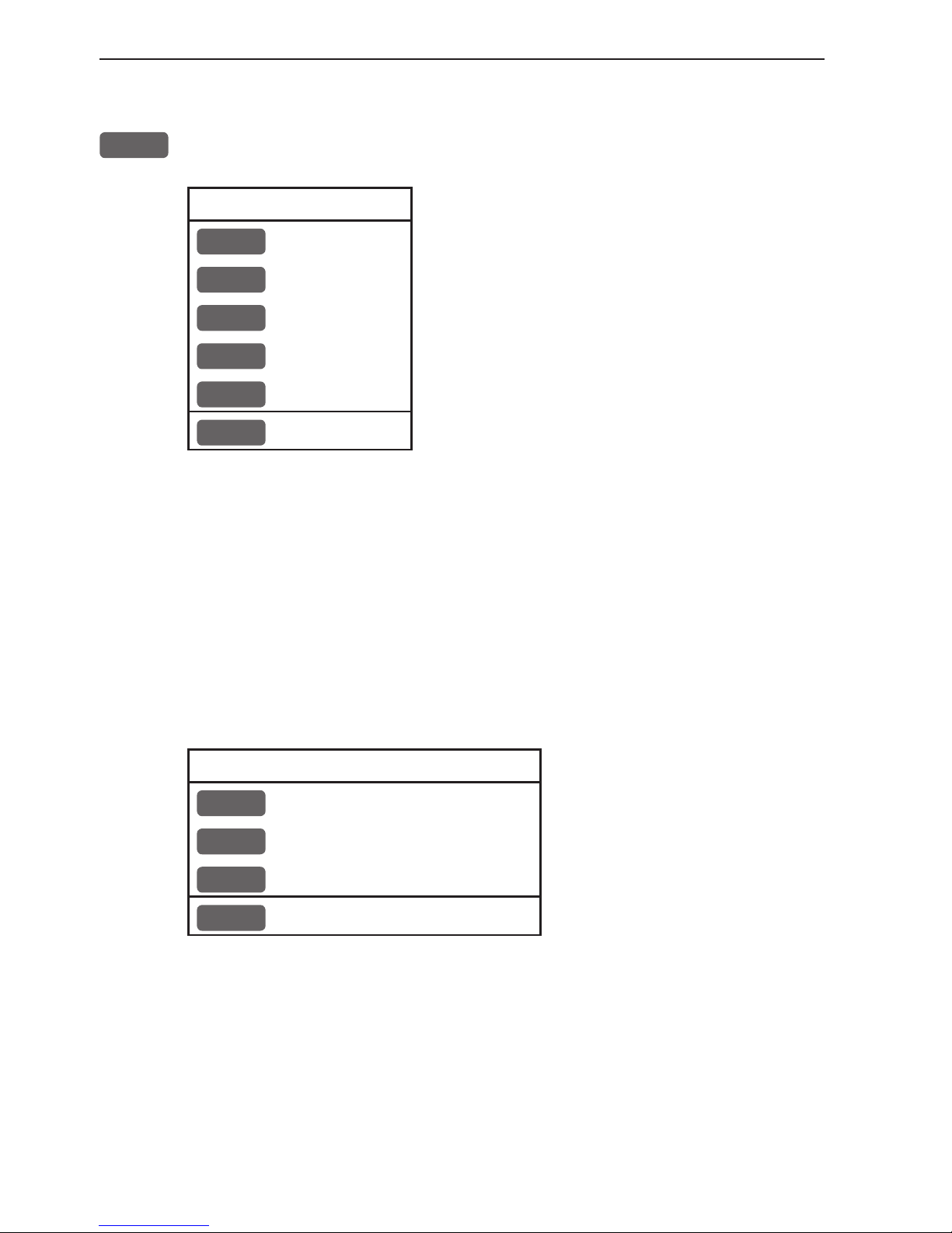
4. Echo menu
2
ECHO
1
Depth & temperature diagram
2
Custom screen
4.1 Depth & temperature diagram
MENU
Call up the menu bar, and...
2,1
activate Depth & temperature diagram
Present water
temperature
and depth.
Depth over
time or distance.
Temp erat ure
over time or
distance.
ADJ
Call Setup for Depth - see example next page.
Page 46
Chapter 4-2 CP44/54 Echo menu
Setup for Depth:
Scale for depth: 0 -> 100 m
Color for depth:
Scale for temperature: 0 -> 20 °C
Color for temperature:
Interval of screen: TIME
Time interval: 5 MIN.
Go to the function you wish to change
0-9
Key in new figures, or...
+/-
change settings
ENT
Confirm changes
Scale for depth - there are six depth scales to choose from, ranging
from 0 -> 10m to 0 -> 3000m. Toggle between values with +/- keys.
Color - for depth and temperature can be changed. Toggle between
available colors by means of the +/- keys.
Scale for temperature - can be set to 0 -> 10°, 0 -> 20°, 0 -> 30°,
10 -> 20°, and -10 -> 10°.
Interval of screen - the interval for updating of screen can be
related to TIME or DISTANCE.
TIME interval can be set in 6 intervals from 5 minutes to 3 hours (+
freeze) for refreshing of the screen.
DISTANCE can be set in 7 intervals, ranging from 0.05nm to 90nm
in order to adjust to the speed of the ship, and you can freeze the
reading.
Page 47
CP44/54 Echo menu Chapter 4-3
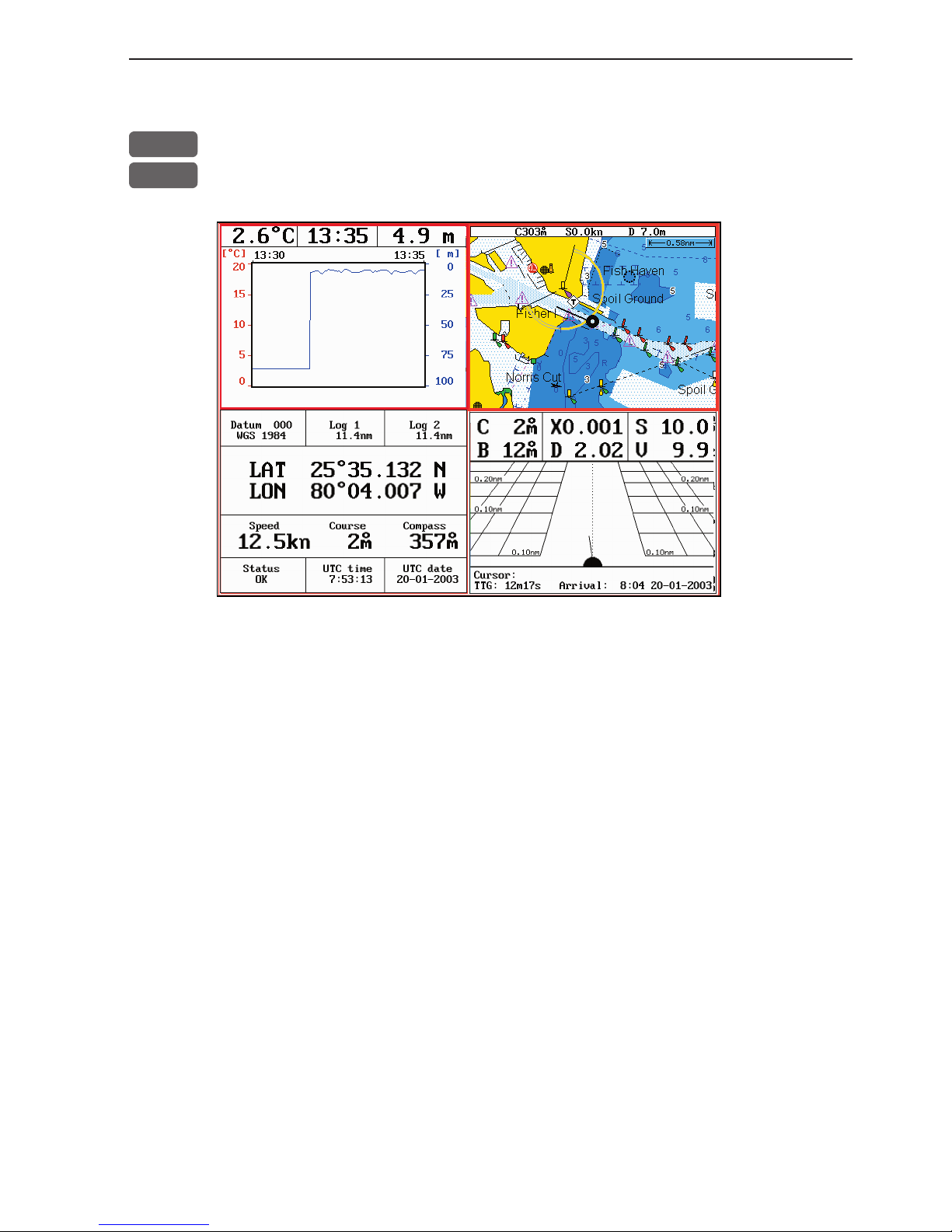
4.2 Custom screen
MENU
Call up the menu bar, and...
2,2
call up the custom screen from Echo menu
The displays, which are not related to the Echo function i.e. all displays except the Depth & temperature diagram in the top left quarter
of the screen, can be exchanged with a different one. It is also possible to change the right half of the screen from two quarter windows
to half screen window, and vice versa. See section 2.1.2. how you go
about changing the displays.
Page 48

Chapter 4-4 CP44/54 Echo menu
Page 49
CP44/54 Pilot menu & navigation examples Chapter 5-1
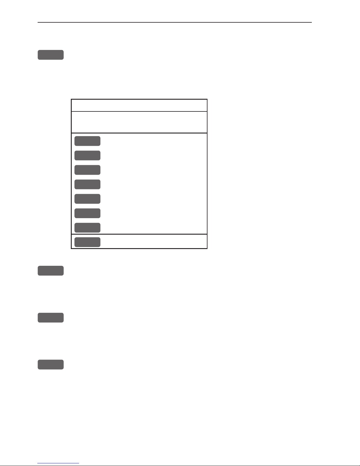
5. Pilot menu
3
PILOT
1
Highway - see section 5.2 & 5.2.1
2
Position - see section 5.3
3
Dual Speed - see section 5.4
4
ETA & AVN - see section 5.5
5
Trim & Highway - see section 5.6
6
Set & Drift - see section 5.7
7
Custom screen 1 - see section 5.8
8
Custom screen 2 - see section 5.8
See also section 5.10 Anchor guard, section 5.11 MOB navigation
and 5.9 Navigation examples.
All functions in the Pilot menu are relevant information to use for
navigation. The two custom screens will present multiple window
combinations (section 5.1), where the window in the top left quarter
of the screen will present a fixed display from the pilot menu.
To access one of the displays via the menu e.g.:
MENU
Call up the menu bar, and...
3,1
press [3] and [1] to call up the Highway display in full screen
5.1 Shortcut to the pages in the pilot-series
The PILOT function is one of the main functions in the CPXX. Each
page under the [PILOT] key will include a window representing the
pilot function. It is not possible to exchange main function displays
with a new display. Refer to section 2.1, 2.1.1 and 2.1.2 for further
information on the display and page system.
Page 50

Chapter 5-2 CP44/54 Pilot menu & navigation examples
Press the [PILOT] key from any display to call up a display in the
pilot-series, and:
PILOT
Long press on the [PILOT] key will toggle between (default):
Highway Custom screen 1 Custom screen 2
From one of the pilot displays i.e. full screen and active window in
the top left quarter:
PILOT
Short press on the [PILOT] key will toggle between:
Highway Position Dual Speed
ETA & AVN Trim & Highway Set & Drift
The sequence of the six displays under the [PILOT] key is available
when a navigation mode is active. If no navigation mode is active,
then the ETA & AVN and the Trim & Highway displays will not be
present in the sequence.
Page 51
CP44/54 Pilot menu & navigation examples Chapter 5-3
5.2 Highway display and Navigation setup
MENU
Call up the menu bar, and...
3,1
load Highway display
When there is no navigation mode active, you will receive the
legend: NAVIGATION IS OFF.
Before starting out in one of the navigation modes, it may be a good
idea to check out the Navigation setup display and see if the default
settings will suit your need.
ADJ
Load Navigation setup
Navigation setup:
Anchor alarm distance: 00.50nm
WP circle alarm: 00.10nm OFF
WP and cursor navigation:
XTE alarm: 00.10nm ON
Navigation mode: RHUMBLINE
Route navigation:
XTE alarm: OFF
Auto waypoint shift: WP-circle
Track navigation:
XTE alarm: 00.10nm OFF
Auto trackpoint shift: WP-circle
Navigation mode: RHUMBLINE
+/-
Toggle between available values, or...
0-9
key in a new alarm limit
ENT
Confirm entry
Anchor alarm distance - When setting anchor, check/change the
preset alarm distance, etc., so you will be warned in case you drift
too far from the anchored position. The alarm distance can be set to
anywhere between 0.01 and 9.99nm. See also section 5.10 Anchor
guard. The alarm will automatically reset once you are inside the
limits again.
WP circle alarm - forms a circle around each waypoint, and the
alarm distance can be set to anywhere between 0.01 and 9.99nm.
Page 52

Chapter 5-4 CP44/54 Pilot menu & navigation examples
The waypoint alarm will be activated when you reach the circle
or the perpendicular line - WP line alarm - crossing through the
waypoint. When “Auto waypoint shift” is set to “WP-circle” it will
override the “WP circle alarm” function.
XTE alarm - forms a corridor along the ideal track. When crossing
one of the boundaries the XTE alarm will be activated.
The alarm will automatically reset once you are inside the limits
again. The alarm distance can be set to anywhere between 0.01 and
9.99nm.
In Route navigation the XTE alarm value can be specified for each
route leg - see section 7.2.
Navigation mode - RHUMBLINE navigation is used for shorter
distances, and GREAT CIRCLE for long trips, especially when
crossing at high latitudes. COMPOSITE navigation is used when all
the legs in a route are not set to the same navigation mode.
Auto waypoint shift - can be set to WP-circle, WP-line or OFF.
When set to WP-circle, the system will change to the next waypoint
in the route after passing the circle line (border).
When set to WP-line, the system will change to next waypoint in the
route after passing the waypoint line (border).
When “Auto waypoint shift” is set to WP-circle, then the alarm
function at the waypoint’s circle will not be activated.
Page 53

CP44/54 Pilot menu & navigation examples Chapter 5-5
5.2.1 Highway display when navigation mode is active
MENU
Call up the menu bar, and...
3,1
load Highway display
With navigation mode active, the highway display will provide a
graphical steering display:
Intended
track
between two
waypoints.
XTE alarm
lines - refer
to sec.8.4 for
alarm setup.
Ship’s position and
course in
relation to
intended
track.
C: Course over ground
X: XTE - Cross-track-error
S: Speed over ground
B: Bearing to approaching point
D: Distance to approaching point
V: Speed towards point
Route: Name/number of active route and aproaching routepoint
BN: Bearing to next point
TDG: Total distance to go to end of route
TTG: Total time to go to end of route
Page 54
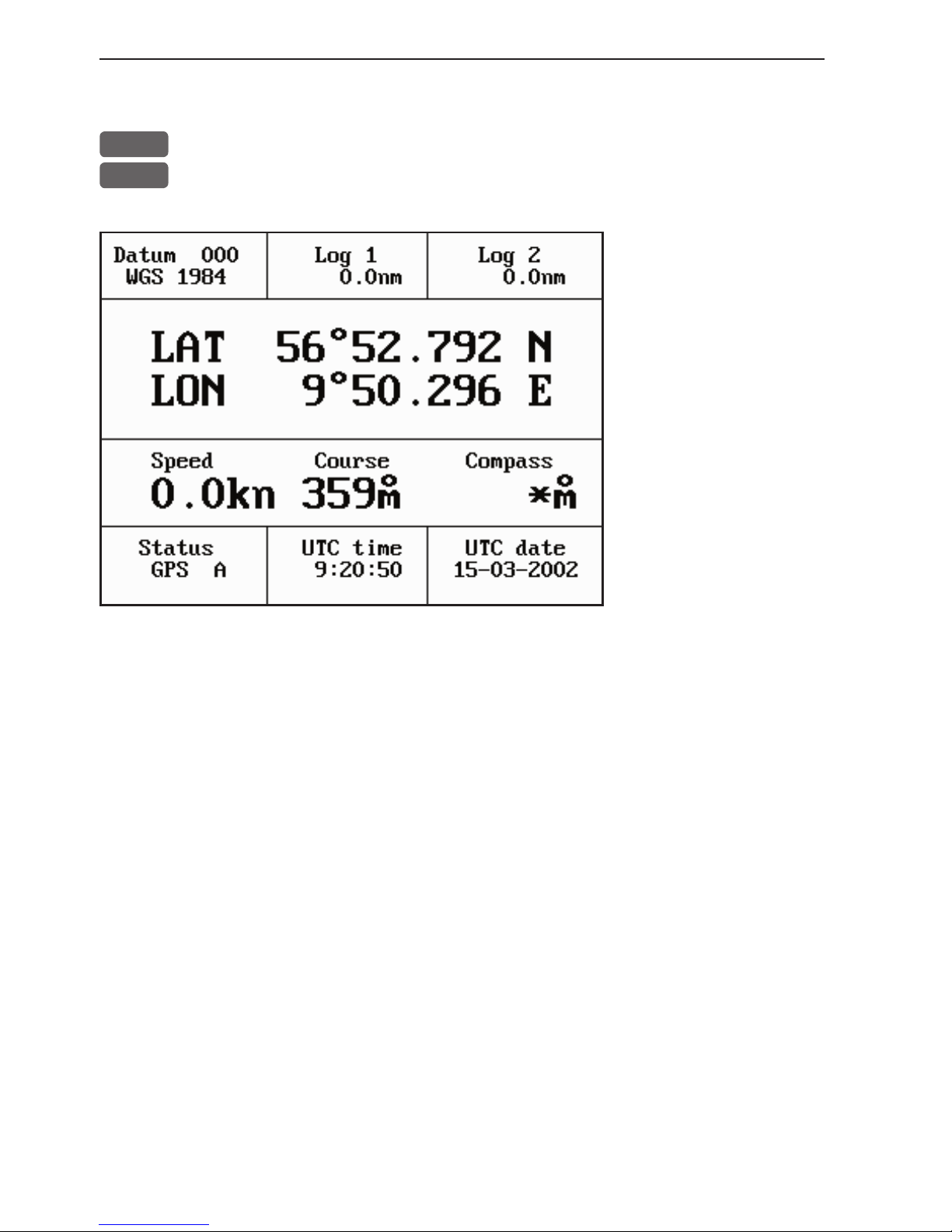
Chapter 5-6 CP44/54 Pilot menu & navigation examples
5.3 Position display
MENU
Call up the menu bar, and...
3,2
load the Position display
Datum currently
selected.
Trip log 1 and 2.
Position with three
decimals in minutes.
Speed over ground.
Course, magnetic or
true.
Depth or Compass
from external sensor.
UTC or local time and date
Time and date in UTC - Universal Time Coordinates - is equal to
standard time in London (GMT). UTC is not affected by the local
summertime adjustments.
Position update - if, for some reason, there is no position update
from GPS or external sensor, the displayed position will start to f lash
and an alarm will be activated to alert the operator. Reset the ‘Position missing’ alarm by [CLR]. The alarm can be set ON/OFF - see
section 6.5. The displayed position will stop flashing once normal
position update is resumed.
Status indicator for reception of satellites:
a (A)= good, b (B)= acceptable, c (C)= fair, or *= no update - see
also “Status indicator and accuracy” below.
With built-in or connected DGPS receiver:
dGPS= differential data received.
DGPS= differential data received and used for corrections.
SDGPS= satellite differential data received and used for corrections.
Page 55

CP44/54 Pilot menu & navigation examples Chapter 5-7
Status indicator and accuracy
Small letters (a,b,c,) indicate that SA is active, and the position
accuracy is expected to be better than 100 meters in 95% of the time.
Capital letters indicate that SA is OFF, and the position accuracy is
then expected to be 15 meters or better in 95% of the time.
dGPS indicates that differential data is received, either via built-in
differential receiver or from external receiver.
DGPS or SDGPS indicates that the position is corrected by the differential data. The accuracy will typically be 2-5 meters for DGPS
and 3-7 meters for SDGPS.
In order to utilize the high accuracy of the GPS system, it is necessary to align the lat/long calculations to the paper charts you are
using. Refer to Position display setup below.
When using C-MAP electronic charts, the datum will be aligned
automatically.
Position display setup
The general Position setup e.g. Display position as: LAT/LON,
Decca or Loran C, etc. is placed in the SETUP menu (section 8.3).
ADJ
From position display, press [ADJ] to load Position display setup:
Pos display setup:
Datum: 000: World Geodetic System 1984
Log 1: 00000.0nm
Log 2: 00000.0nm
Additional data: COMPASS
Go to the function you wish to change
CLR
Reset log
Page 56

Chapter 5-8 CP44/54 Pilot menu & navigation examples
0-9
Key in new values, or...
+/-
Toggle between available values
ENT
Confirm editing and return to the Position display
Datum - is preset to WGS 1984 (World Geodetic System 1984), but
can be changed to any of the 118 datums listed in Appendix B e.g.
to match old paper charts or trackplotter data from RS2500/RS4000
(datum #002 European 1950).
The position in the position display and NMEA output (GLL+GL2)
will refer to the selected datum. To select a new datum: place the
cursor next to “Datum” and key in a new number or go two spaces to
the right (000
) and leaf through the datum list with +/-.
The datum in the chart display is fixed i.e. WGS84.
Log - reset log or insert alternative start figure by altering the value
in the “Log 1” and/or “Log 2” line. Press [CLR] to reset the figure,
and press the numeric keys 0-9 to alter the figure.
Additional data - can be set to COMPASS, DEPTH or ANT.
HEIGHT.
COMPASS will show heading from connected sensor.
DEPTH will be shown when NMEA depth data is received from
connected depth instrument.
ANT. HEIGHT will indicate the actual antenna altitude (height
above sea level).
Page 57

CP44/54 Pilot menu & navigation examples Chapter 5-9
5.4 Dual speed display (trawling speed display)
The analogue differential speed indicator will show how much the
present speed varies from the average speed.
If the difference exceeds +/- 3 knots (or km/h or miles/h), an arrow
will appear which will be pointing out of the scale.
MENU
Call up the menu bar, and...
3,3
load Dual Speed display
Water speed
readout from
connected
log transducer.
Position with three decimals in minutes.
Analogue differential speed indicator (scale).
Dynamic speed with short filtering time is reacting quickly to
changes, but is also more unsteady.
Average speed with long filtering time gives a very stable reading.
Course over ground, magnetic (m) or true (°).
How to reset dual speed:
ADJ
Open for change
ENT
Reset dual speed, or...
MENU
exit function without making any changes
Page 58

Chapter 5-10 CP44/54 Pilot menu & navigation examples
5.5 ETA & AVN display
MENU
Call up the menu bar, and...
3,4
load the ETA & AVN display
-to receive any data will require that navigation mode is active.
ETA - Estimated Time of Arrival - refers to the inserted local time,
and can be calculated to any point used for navigation.
AVN - Approximate Velocity Necessary - is automatically calculated
in knots after you key in the planned arrival time and date.
In route navigation the approaching point and present speed over
ground (AUTO) is automatically used for the calculation.
You can change to any waypoint in the route and also insert an alternative ETA speed (MANUAL).
ADJ
Open for change - in route navigation the approaching point is auto-
matically suggested and present speed is used for calculation.
If required - go to, and...
0-9
Insert alternative routepoint - only in Route navigation.
Go to ETA mode, and...
+/-
Select AUTO or MANUAL
Page 59

CP44/54 Pilot menu & navigation examples Chapter 5-11
Go to AVN, and...
0-9
Insert time and date
ENT
Confirm entry
5.6 Trim & Highway display
Some of the readings rely on data from external log and compass.
The Trim & Highway display will provide information on actual and
mean speed, velocity and water speed - see also section 5.7 Set &
Drift display.
MENU
Call up the menu bar, and...
3,5
load the Trim & Highway display
B: Bearing.
X: XTE
Cross-trackerror.
D: Distance
to point.
ADJ
Open for change
ENT
Reset mean speed indication in display
Page 60
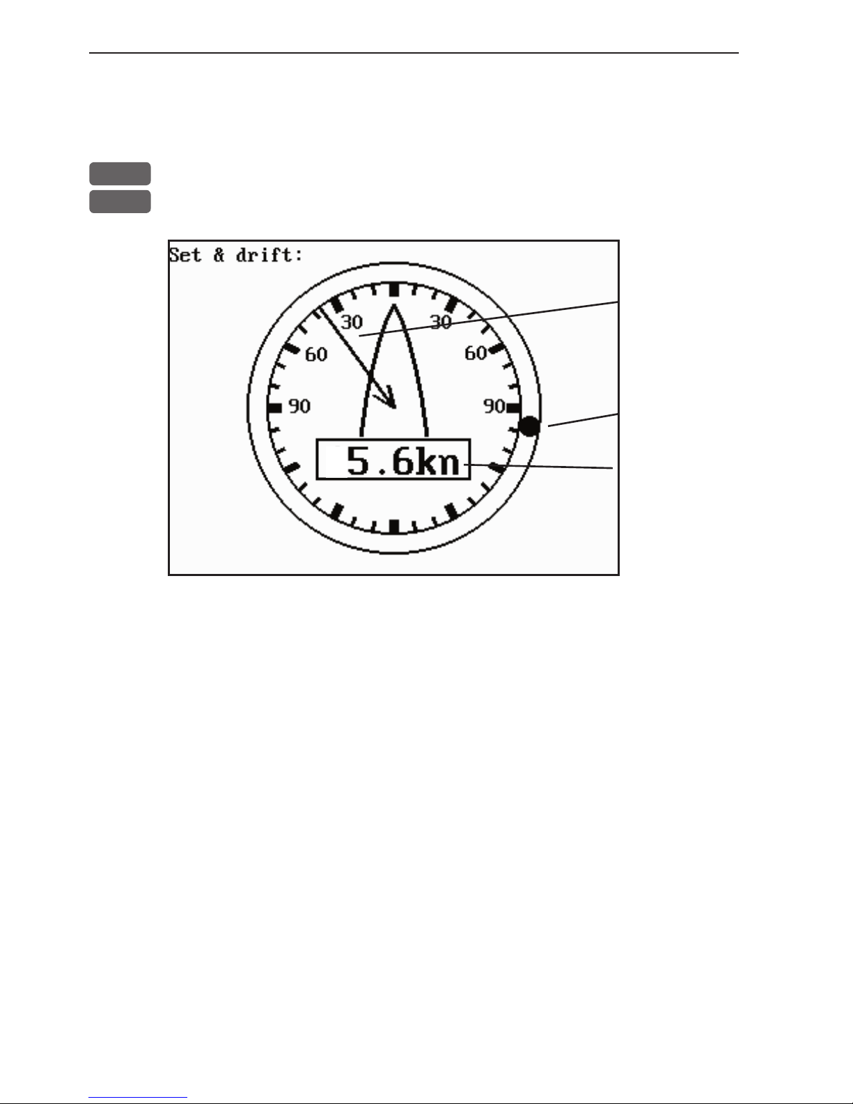
Chapter 5-12 CP44/54 Pilot menu & navigation examples
5.7 Set & Drift display
The readings rely on data from external log and compass.
MENU
Call up the menu bar, and...
3,6
load the Set & Drift display
Relative
direction.
True
direction.
Speed.
The Set & Drift display will show how fast the current is moving
in knots; in what direction (true) it is moving and what direction in
relation to the vessel (relative).
To obtain information on actual and mean speed, velocity and water
speed - see the Trim & Highway display in section 5.6.
Page 61
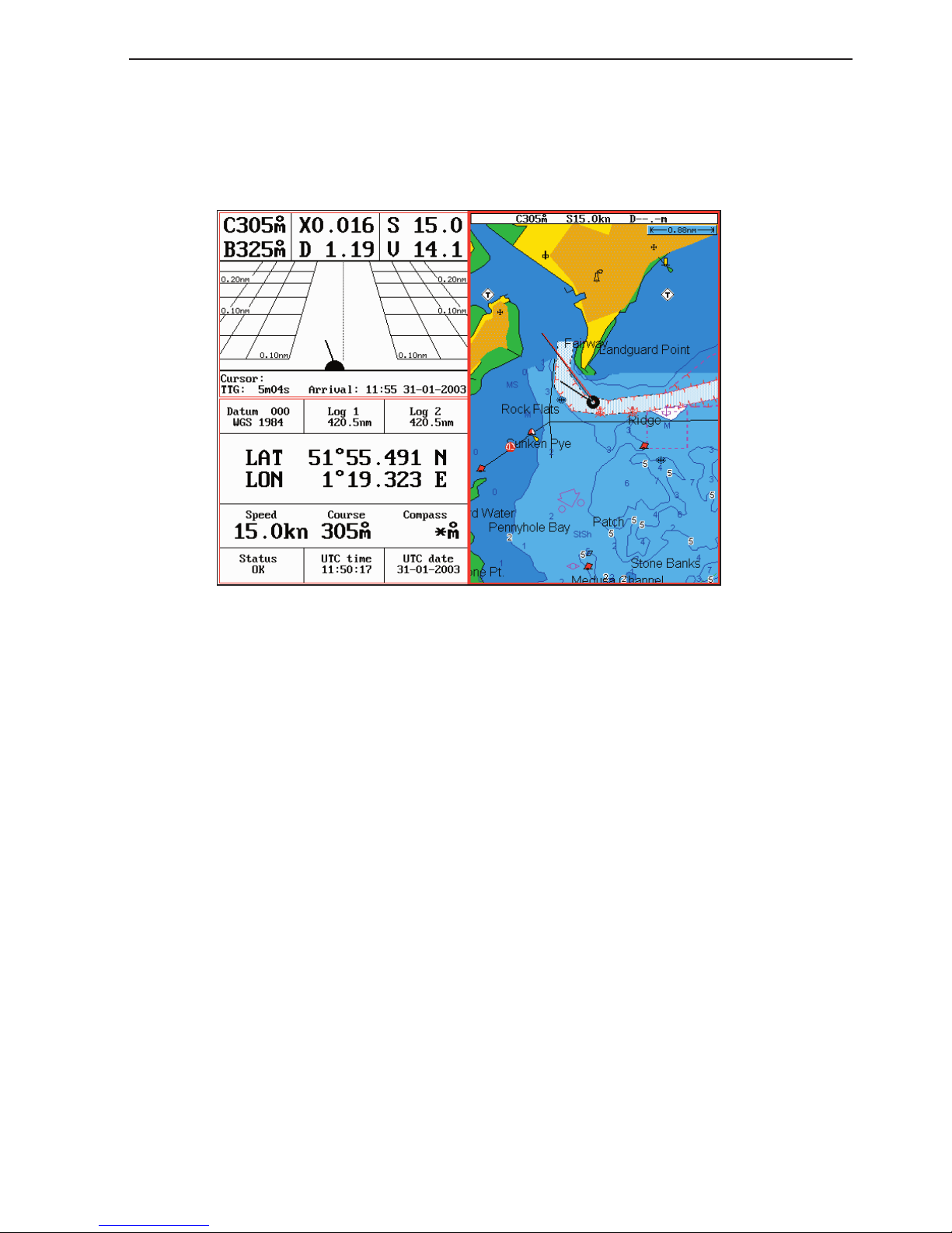
CP44/54 Pilot menu & navigation examples Chapter 5-13
5.8 Pilot custom screens
The two custom screens in thepilot menu consist of multiple window
combinations e.g.:
The displays presented in the example above are the default displays
for Custom screen 1 under the PILOT menu.
Top left quarter window shows the Highway display, which can be
exchanged with a different display from the pilot menu, either by
single press on the [PILOT] key which will toggle through all the
displays available from the pilot menu, or via the menu.
Bottom left quarter window shows the Position display, which can be
exchanged with any display that will fit into a quarter window.
Right half screen shows the Chart display, which can be exchanged
with a different one in same size window, or you can change the
window combination from half to two quarter windows.
These custom screens can actually have several displays presented
from the pilot menu. However, when the top left window is active
and you toggle through the available displays from the pilot menu,
the sequence will skip the displays already presented on the screen,
as they can not appear twice on the same screen.
See section 2.1.2 how you go about changing the displays.
Page 62

Chapter 5-14 CP44/54 Pilot menu & navigation examples
5.9 Navigation examples
5.9.1 Chart/cursor navigation. 5.9.2 Waypoint navigation.
5.9.3 Route navigation. 5.9.4 Track navigation.
Relevant for all navigation modes are:
- the highway display with graphical steering - section 5.2.1.
- the ETA & AVN display with Estimated Time of Arrival and
Approximate Velocity Necessary to reach a given point at a specific
time - section 5.5.
- the *Trim & Highway display with information on actual and mean
speed over ground, velocity (VMG) and water speed - section 5.6.
- the *Set & Drift display with indication of how fast the current
is moving in knots, in what direction (true) it is moving and what
direction in relation to the vessel (relative) - see section 5.7.
* These readings rely on data from external log and compass.
With the [PILOT] key you can toggle between all the displays in the
pilot-serie - see section 5.1 Shortcut to the pages in the pilot-serie.
5.9.1 Cursor navigation
Cursor navigation is the easiest and most straightforward way of
navigation - point and go!
CHART
Shortcut to chart display
Press the cursor key to activate the cursor, then move the cursor to
your destination
GOTO
Call up the GOTO menu
1
Select Cursor navigation mode
A course line will now be drawn from actual position (ship’s position) to destination point (cursor’s position).
Page 63

CP44/54 Pilot menu & navigation examples Chapter 5-15
Next destination: While on the way, you can easily move the cursor
to the next destination, and when ready to change navigation leg...
GOTO
Call up the GOTO menu
2
Restart to approaching point
- a new course line will be drawn from ship’s position to destination.
To turn NAV mode off again: Press [GOTO], [3].
5.9.2 Waypoint navigation
To start Waypoint navigation will require that at least one waypoint
is stored in the memory. Refer to section 3.4.9 PLOT menu.
CHART
Shortcut to chart display
Place cursor on destination waypoint
GOTO
Call up the GOTO menu, and...
2
Select Waypoint navigation mode
This will activate the pop-up window “Navigate to WP” - and if the
highlighted waypoint is the point you wish to sail to, then just press
[ENT] to start navigation.
However, if you wish to sail to a different waypoint:
+/-
Scroll up/down in the waypoint list, or...
0-9
Key in the number/name of the waypoint you wish to sail to
ENT
Start navigation
A course line will now be drawn from ship’s position to destination
waypoint.
To turn NAV mode off again: Press [GOTO], [3].
Page 64

Chapter 5-16 CP44/54 Pilot menu & navigation examples
5.9.3 Route navigation
To start Route navigation will require that at least one route is stored
in the memory. Refer to section 3.4.9 PLOT menu.
There are two ways to start Route navigation:
• From the chart:
Place cursor on the routepoint you wish to start your navigation
from
GOTO
Call up the GOTO menu, and...
3
Select Route navigation mode
This will activate the pop-up window “Navigate in route” with the
selected routepoint as first destination point. Check if any of the current settings need to be changed e.g. forward or reverse direction in
route.
ENT
Start navigation
• From the chart, without first placing cursor on a routepoint:
GOTO
Call up the GOTO menu, and...
3
Select Route navigation mode
This will activate the pop-up window “Navigate in route” from
where you can choose which route you wish to select for navigation:
+/-
Scroll up/down in the route list until the correct route number /
name appears
Use the cursor to move around in the window if anything needs to be
changed - such as Direction in route, etc.
0-9
Key in the number of the first routepoint you wish to sail to
ENT
Start navigation
A course line will now be drawn from ship’s position to the first
Page 65

CP44/54 Pilot menu & navigation examples Chapter 5-17
routepoint.
GOTO
Pressing [GOTO] from chart display during navigation will activate
an INFO window with the following functions to choose from:
1. Advance (to next routepoint)
2. Restart to approaching point (in case you have drifted off course)
3. Turn NAV OFF
5.9.4 Track navigation
A track is created by a series of trackpoints connected by track lines.
Using a track for navigation is somewhat like navigating in a route
with many waypoints.
To start Track navigation will require that at least one track is stored
in the memory. Tracks which are not yet completed can not be used
for navigation. Refer to section 7.5 Start / Stop track.
There are two ways to start Track navigation:
• From the chart:
Place cursor on the track at the point where you wish to start your
navigation from
GOTO
Call up the GOTO menu, and...
4
Select Track navigation mode
This will activate the pop-up window “Navigate in track” with the
selected trackpoint as first destination point. Check if any of the current settings need to be changed.
ENT
Start navigation
• From the chart, without first placing cursor on a track:
GOTO
Call up the GOTO menu, and...
4
Select Track navigation mode
Page 66

Chapter 5-18 CP44/54 Pilot menu & navigation examples
This will activate the pop-up window “Navigate in track” from
where you can choose which track you wish to select for navigation:
+/-
Scroll up/down in the track list until the correct track number / name
appears
Use the cursor to move around in the window if anything needs to be
changed - such as Direction in track, etc.
0-9
Key in the number of the first trackpoint you wish to sail to
ENT
Start navigation
A course line will now be drawn from ship’s position to the first
point of destination.
GOTO
Pressing [GOTO] from chart display during navigation will activate
an INFO window with the following functions to choose from:
1. Advance (to next trackpoint)
2. Restart to approaching point (in case you have drifted off course)
3. Turn NAV OFF
Page 67

CP44/54 Pilot menu & navigation examples Chapter 5-19
5.10 Anchor guard
GOTO
Call up the GOTO menu, and...
5
activate the anchor guard function
-the chart display will provide an impression of the vessel’s position
in relation to the alarm circle.
To check/change the preset alarm distance:
MENU
Call up the menu bar, and...
3,1
load the highway display
ADJ
Enter the navigation setup display
0-9
Key in a new value with numeric keys
ENT
Confirm the change
To turn Anchor guard off again:
GOTO
Call up the GOTO menu, and...
3
turn anchor guard off
5.11 MOB alarm and navigation
The MOB - Man overboard - alarm and display will be activated if
you press the [MOB] key on the CPXX keypad and hold it depressed
for two seconds, or activate an external MOB switch (hold five seconds) and then press the [ENT] key to start MOB navigation.
The MOB display will provide all relevant data for an efficient
rescue operation - refer to details on the rear of the first page of the
manual.
To turn the MOB function off again:
GOTO
Call up the GOTO menu, and...
3
turn the MOB function off
To check the last activated MOB position:
MENU
Call up the menu bar, and...
5,7
select MOB data
Page 68

Chapter 5-20 CP44/54 Pilot menu & navigation examples
Page 69
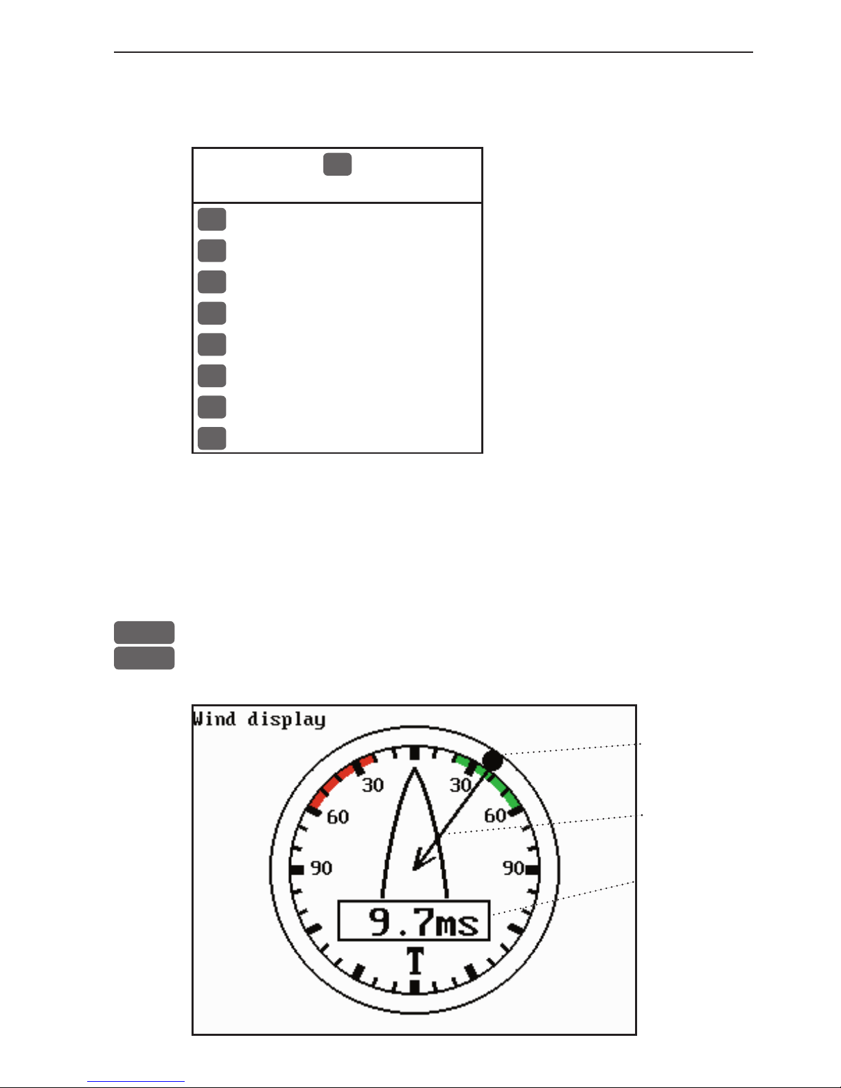
CP44/54 Miscellaneous menu Chapter 6-1
6. Miscellaneous menu
4
MISC
1
Wind - see section 6.1
2
Speed diagram - see section 6.2
3
Decca lanes - see section 6.3
4
Loran C - see section 6.4
5
Satellites - see section 6.5
6
DGPS - see section 6.6
7
SDGPS - see section 6.7
8
DSC info - see section 6.8
6.1 Wind display
The CPXX is ready to present wind data from connected instruments.
MENU
Call up the menu bar, and...
4,1
load the ‘Wind instrument’ display
True wind
direction.
Wind relative to vessel.
Wind speed,
relative or
true.
Page 70

Chapter 6-2 CP44/54 Miscellaneous menu
ADJ
Load Setup for Wind display
Setup for Wind:
Damping level: MEDIUM
Relative wind scale: NORMAL
Wind angle offset: 000°
Show wind speed as: RELATIVE
Wind speed unit: METERS/SECOND
Go to the function you wish to change
+/-
Toggle between settings, or...
0-9
Key in new figure
ENT
Confirm entry and return to Wind display
Damping level - can be set to LOW, MEDIUM or HIGH. The higher
level the more steady and slow reacting reading.
Relative wind scale - can either be set to NORMAL (0-180°) or
MAGNIFIED (0-60°).
Wind angle offset - can be from 0 to 360°.
Show wind speed as - TRUE or RELATIVE.
Wind speed unit - can be either METER/SECOND, KNOTS,
KILOMETERS/HOUR or MILES/HOUR.
Page 71
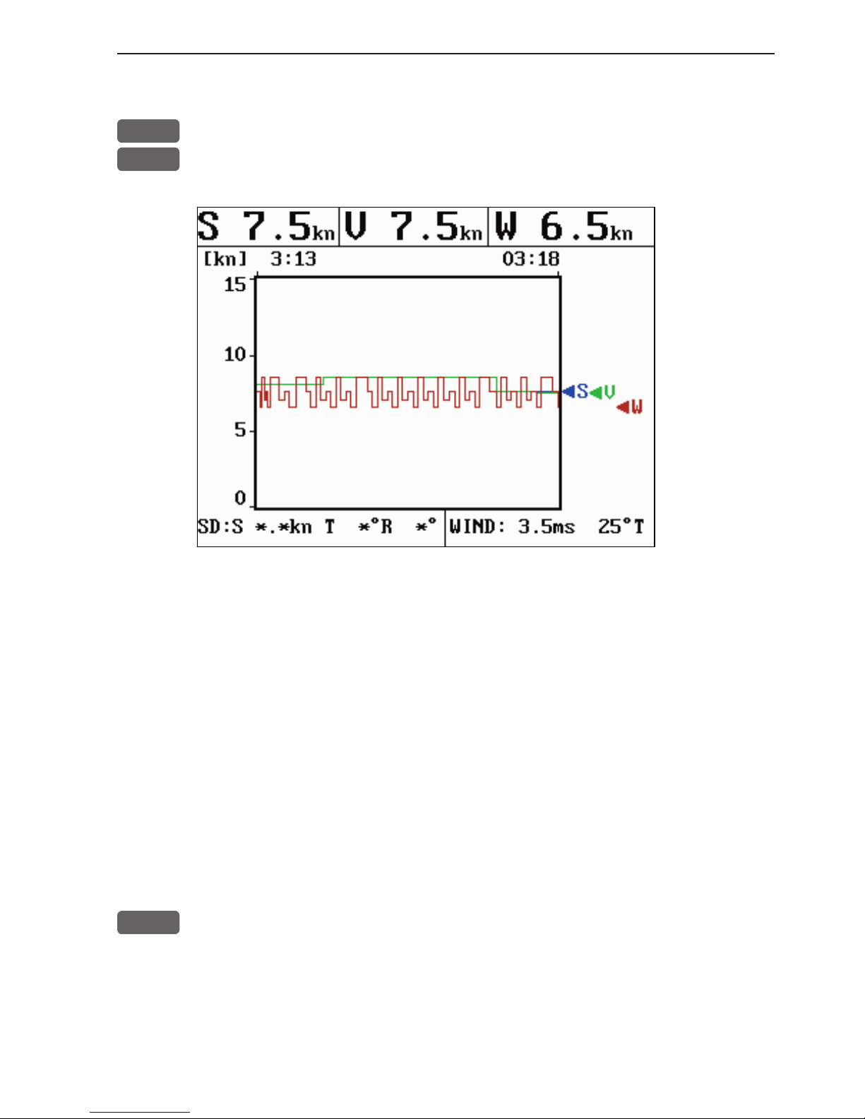
CP44/54 Miscellaneous menu Chapter 6-3
6.2 Speed diagram
MENU
Call up the menu bar, and...
4,2
load “Speed diagram”
S= Speed over ground.
V= Velocity towards waypoint.
W*= Speed through water.
SD (Set and drift)*= Speed and direction, true or relative.
WIND*= Speed and direction.
* Connection to external sensors is required.
ADJ
Call “Speed diagram setup”
- see next page.
Page 72
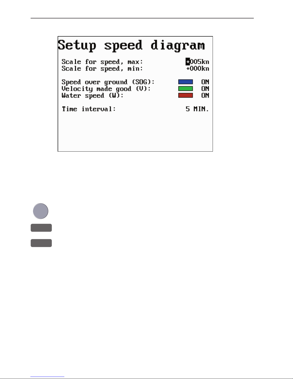
Chapter 6-4 CP44/54 Miscellaneous menu
The scale for the speed diagram can be adjusted in this display.
Time interval can be set in 8 intervals from 1 minute to 3 hours and
freeze.
Go to the function you wish to change
+/-
Key in new figure or change setting
ENT
Confirm entry and return to Speed diagram
Page 73

CP44/54 Miscellaneous menu Chapter 6-5
6.3 Decca lanes
MENU
Call up the menu bar, and...
4,3
load decca chain display
+/-
Leaf through the available chains - see below.
ENT
Confirm entry
To change the position readouts to decca mode, see section 8.2 under
Pilot/Position setup, where ‘Display position as’ can be toggled to
‘Decca’.
List of decca chains:
00 S Baltic 0A 24 Skagerak 10B
01 Vestlandet 0E 25 N Persian 5C
02 SW British 1B 26 S Persian 1C
03 North Humber 2A 27 Bombay 7B
04 Holland 2E 28 Calcutta 8B
05 British 3B 29 Bangladesh 6C
06 Lofoten, Norway 3E 30 Hokkaido 9C
07 German 3F 31 Tohoku 6C
08 N Baltic 4B 32 Kyusyu 7C
09 NW Spanish 4C 33 Namaqua 4A
10 Trondelag (N) 4E 34 Cape chain 6A
11 English 5B 35 E Province 8A
12 N Bothnian 5F 36 Dampier 8E
13 S Spanish 6A 37 Port Hedld 4A
14 N Scottish 6C 38 Hokuriku 2C
15 Finland 6E 39 Newfoundld. 2C
16 Danish 7B 40 Cabot strt 6B
17 Irish 7D 41 Nova Scotia 7C
18 Finnmarken 7E 42 Salaya 2F
19 French 8B 43 Kanto 8C
20 S Bothnian 8C 44 SW Africa 9C
21 Hebridean 8E 45 Natal 10C
22 Frisian 9B 46 Shikoku 4C
23 Helgeland 9E
Page 74

Chapter 6-6 CP44/54 Miscellaneous menu
6.4 Loran C
MENU
Call up the menu bar, and...
4,4
load Loran C chain display
+/-
Leaf through the available chains - see listing below.
If required, go to the slaves, and...
+/-
Toggle between available slaves (not all chains have more than one
slave)
0-9
...and it is possible to alter the figures in the time delay
If required, go to Offset, and key in a positive or negative offset
0-9
Key in a positive or negative offset to the time delay (toggle positive/
negative with +/-)
ENT
Confirm entry
To change the position readouts to Loran C mode, see section 8.2
under Pilot/Position setup, where ‘Display position as’ can be toggled to ‘Loran C’.
List of Loran C chains:
Central Pacific
Gulf of Alaska
Southeast U.S.
Great Lakes
Northeast U.S.
Canadian West Coast
Canadian East Coast
Labrador Sea
West Coast U.S.
North Pacific
4990
7960
7980
8970
9960
5990
5930
7930
9940
9990
Commando Lion
North West Pacific
Norwegian Sea
Mediterranean Sea
Icelandic
Saudi Arabia South
Saudi Arabia North
Eastern U.S.S.R.
Western U.S.S.R.
5970
9970
7970
7990
9980
7170
8990
7950
8000
Page 75

CP44/54 Miscellaneous menu Chapter 6-7
6.5 Satellite status
MENU
Call up the menu bar, and...
4,5
load satellite status display
The display will show which satellites are currently being used for
computation of data. It will show their position together with SNR
- Signal to Noise Ratio. The bottom line shows the status of all the
satellites in the GPS system, starting from left to right with the numbers 1 to 32.
Satellite status (bottom line):
+ indicates the satellite is healthy.
- excluded or non-existing satellite.
0 satellite data is faulty.
* satellite is manually excluded.
You may want to exclude a satellite manually in case a particular
satellite is disturbing the navigation:
ADJ
Open for change, and...
Place the cursor on the satellite in the bottom line you wish to exclude
-
The minus key will exclude the satellite, and...
+
the plus key will reinstate it
ENT
Confirm entry
Page 76
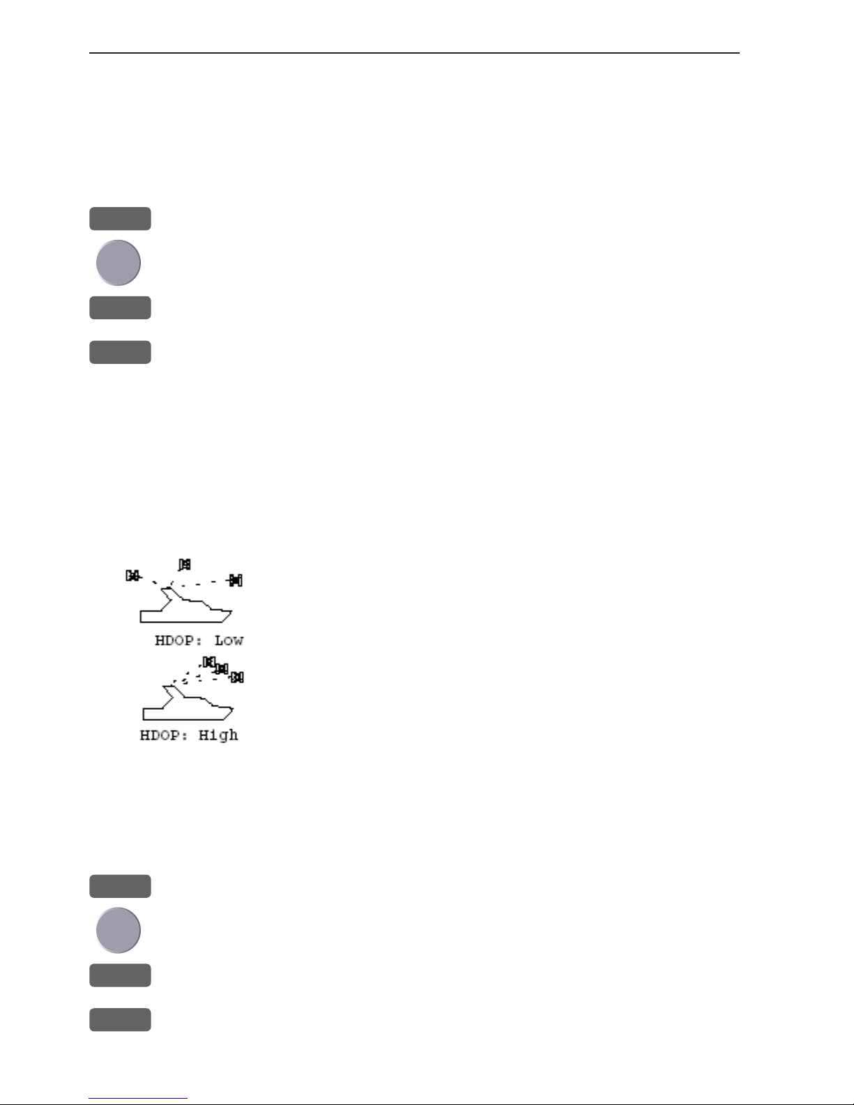
Chapter 6-8 CP44/54 Miscellaneous menu
Position update alarm
“Alarm” in the satellite status display is preset to “OFF”. If the
received position data is invalid, the position shown in the position
display will start to flash. A position update alarm can be set ON/
OFF from the satellite status display [MENU],[4],[5]:
ADJ
Open for change
Go to “Alarm”
+/-
Toggle alar m ON/ OFF
ENT
Confirm entry
Reset the alarm by [CLR].
HDOP, PDOP and DOP limits
The value of HDOP (horizontal dilution of precision) expresses “the
quality” of the satellite geometry in relation to 2D positioning and a
fixed antenna altitude.
PDOP (position dilution of precision) is equivalent to 3D
positioning. The values will typically stay between 1.3
and 8. The lower the value the higher the “quality”. A
poor geometry might produce a value of more than 20.
If preset DOP limit is exceeded (indicated by * in the
position display) it will cause the position updating to
stop until it once again is within the limit.
The DOP limit can be changed manually, but should not be set to
higher than 8 (default), as this may result in poor accuracy i.e. false
position. To change the DOP limit from the satellite status display
[MENU], [4], [5] :
ADJ
Open for change
Go to DOP limit (6-20), and...
0-9
Insert new limit
ENT
Confirm entry
Page 77

CP44/54 Miscellaneous menu Chapter 6-9
6.6 DGPS information (optional)
The DGPS - differential position corrections - can be provided from
a built-in module, which is preset to full automatic operation, or
from connected DGPS receiver - see “Status indicator” in position
display.
List of beacon stations is available in addendum, part no.
183- 0122-501.
MENU
Call up the menu bar, and...
4,6
load DGPS setup display (with built-in module)
To re c eive
valid differential data
will require
that the
navigator
is locked in
on a beacon
station.
Frequency (station) and bit rate can be selected manually:
ADJ
Open for change, and...
Go to the function you wish to alter
+/-
Toggle the function, or...
0-9
insert new figures
ENT
Confirm entry
Beacon - informs the name of the beacon the navigator is locked on
to (if any), together with indication of bearing and distance.
Page 78

Chapter 6-10 CP44/54 Miscellaneous menu
Status - can either be:
LOCKED = locked on a beacon and receiving differential data.
NOT LOCKED = not locked on a becon and receiving no differential data.
NOT INSTALLED = there is no built-in DGPS module in unit.
NOT IN USE = external DGPS receiver applied.
Beacon is monitored - YES or NO.
If YES it should be safe to rely on the received differential data,
because the beacon station’s performance is under observation.
If NO, then you have to use the received differential data with caution, as there is no guarantee it is not faulty.
Frequency - the frequency of the beacon station can be set manually
if known. However, when left in AUTO the navigator will always
search for the nearest station with a good signal strength.
Bit rate - indicates bits per second, and can be set manually to 25,
50, 100 or 200 bps.
Signal strength - a good signal strength is 20 and up.
Signal to noise ratio (SNR) - should be 8dB and up.
Message - type 16 message will be displayed when received from
the DGPS system. The contents of this message could be something
to do with the performance of the system. Temporarily out of service
etc.
Page 79

CP44/54 Miscellaneous menu Chapter 6-11
6.7 SDGPS information
The SDGPS - satellite differential GPS - is preset to full automatic
operation, which means that the system will utilize the position corrections from either differential GPS stations (refer to section 6.6)
or satellite differential GPS signals from WAAS, EGNOS or MSAS
(refer to section 6.7.1).
MENU
Call up the menu bar, and...
4,7
load SDGPS setup display
SDGPS setup:
SDGPS select mode: AUTO
Uses corrections from: *****
CH A N NEL 1: sat.no.: **** ****
Corrections: NONE
Integrity messages ok: NO
Range used for position fix: NO
Type 0 warning received: NO
CH A N NEL 2: sat.no.: **** ****
Corrections: NONE
Integrity messages ok: NO
Range used for position fix: NO
Type 0 warning received: NO
Ignore type 0 warnings: NO
ADJ
Open for change
Go to the function you wish to alter (see below)
+/-
Toggle the fu n c t i on
ENT
Confirm entry
SDGPS select mode determines which differential corrections can
be used in the position determination:
AUTO is default mode. Local area DGPS corrections are used when
available. If not available, then SDGPS corrections are used (if these
are available).
MANUAL mode: SDGPS corrections are used (if available). Local
area DGPS corrections are not used.
PAS SI VE mode: SDGPS corrections are never used.
Page 80

Chapter 6-12 CP44/54 Miscellaneous menu
Uses corrections from - indicates which differential corrections
(DGPS or SDGPS) are currently used for position determination.
CHANNEL 1: sat.no. - indicates which satellite number and name
is currently tracked/searched by channel 1, and what is the tracking
state.
Corrections - indicates if corrections are being received on this
channel. If YES: is the quality of the reception sufficiently high for
the corrections to be usable.
NONE: no corrections are received.
RECEIVED: corrections are received, but of insufficient quality.
USABLE: corrections are received and of sufficient quality.
USED: corrections received on this channel are used in the position
determination.
Integrity messages ok - the SDGPS system will transmit messages
concerning the integrity of the GPS satellites. This line will indicate
whether such messages are received and reliable.
Range used for position fix - if the receiver is tracking a particular
SDGPS satellite, it “knows” the distance to that satellite. This line
will indicate whether the distance is used in the position determination.
Type 0 warning received - if an SDGPS satellite is not operating according to specifications it will transmit a so-called “Type 0
warning”. In this situation, the receiver will not use any information
that it might receive from that satellite. Until the SDGPS system is
declared operational, the SDGPS satellites will always transmit Type
0 warnings.
It is possible (but not recommendable) to override the Type 0 warn-
ings - refer to last line in SDGPS setup: “Ignore type 0 warnings:
NO” should be changed to “YES”.
Page 81

CP44/54 Miscellaneous menu Chapter 6-13
6.7.1 Satellites in SDGPS system
The SDGPS system consist of eight orbiting geostationary satellites.
It is, however, not expected to become fully employed till sometime
in 2003. In the meantime, the system will have limited usage but will
be available to all users with the latest Simrad equipment, such as
the CPXX Chartplotter.
Number Name System Area
120
AOR-E EGNOS - EU
Atlantic ocean region east
122
AOR-W WAAS - US
Atlantic ocean region west
124
ARTEMIS EGNOS - EU
126
INMARSAT EGNOS - EU
129
MTSAT-1 MSAS - JAPAN
131
IOR EGNOS - EU
Indian ocean region
134
POR WAAS - US
Pacific ocean region
137
MTSAT-2 MSAS - JAPAN
Tracking state
The letter indicating the tracking state will appear immediately after
the satellite number in the display.
Letter indication: - means that the receiver is:
S searching for satellite.
D trying to synchronize to data stream.
C code locked to signal.
P phase locked to signal.
Page 82

Chapter 6-14 CP44/54 Miscellaneous menu
6.8 DSC info (feature prepared for future DSC VHF)
To receive an iDSC Alarm and Message from VHF will require that
the CPXX is connected to a compatible Simrad VHF radiotelephone.
The data is transmitted via the NMEA sentence:
$PSIMB,1,0,*hh<CR><LF>
Manufacturer’s code: “SIMB” Simrad, message B.
Datafelt 1: “
1” activate iDSC alarm; “0” inactive iDSC alarm.
Datafelt 2: “
0” iDSC alarm acknowledged by [CLR];
“
1” iDSC alarm acknowledged by [ENT].
The message from the VHF will appear in a pop-up window together
with an acoustic alarm. Press [CLR] to reset the alarm, or press [ENT]
to stop alarm and select the suggested channel for communication
- refer to the VHF manual for further details.
To view the last received message:
MENU
Call up the menu bar, and...
4,8
load the DSC info display
Page 83

CP44/54 Waypoint / route menu Chapter 7-1
7. Waypoint / route menu
5
WP/RTE
1
Waypoints - see section 7.1
2
Routes - see section 7.2
3
Route calculation - see section 7.3
4
Lines - see section 7.4
5
Tracks - see section 7.6
6
Targets - see section 7.7
7
MOB data - see section 7.8
8
Data transfer - see section 7.9 + 7.10
7.1 Waypoints stored in the memory
The waypoint list will appear in alphabetical order and will include
the waypoint’s position in lat/long. To edit one of the stored waypoints:
MENU
Call up the menu bar, and...
5,1
load waypoint list
Waypoint: WP 2
x WP 1 57°14.853N 9°51.966E
x WP 10 55°59.954N 10°47.247E
x WP 11 55°59.203N 11°15.562E
x WP 2 57°20.289N 10°01.404E
x WP 3 57°24.990N 10°15.561E
x WP 4 57°24.990N 10°39.831E
x WP 5 57°14.490N 10°58.708E
x WP 6 57°01.385N 11°06.798E
x WP 7 56°50.773N 10°47.921E
Number of stored waypoints: 11
Page 84

Chapter 7-2 CP44/54 Waypoint / route menu
A-Z
Insert name of waypoint you wish to edit, or...
+/-
Leaf through waypoints with +/- keys or up/down cursor
ENT
Open for editing
Place the cursor on the function you wish to change
0-9
Key in new figures, or...
+/-
toggle between available values
PLOT
Move the position to ship’s position
ENT
Confirm entry and return to WP list
Plot new waypoints with the [PLOT] key - refer to section 3.4.9.
7.1.1 Delete waypoints via menu
MENU
Call up the menu bar, and...
5,1
load waypoint list
+/-
Select waypoint you wish to delete
ENT
Open for editing
WIN
Delete waypoint
CLR
Confirm that you want to delete the selected waypoint, if not sure:
press [MENU] to exit the display without having made any changes.
Edit waypoints directly on the chart via info windows, refer to sec-
tion 3.4.3.
Page 85

list
list
CP44/54 Waypoint / route menu Chapter 7-3
7.2 Routes stored in the memory
The route list will keep a record of all the saved routes in the system.
It will provide information on number of waypoints in the route etc.
Existing routes can be altered via the route list - see further on in
this chapter, or directly on the chart via info windows - refer to sections 3.4.4 and 3.4.5. To delete a route - refer to section 7.2.1.
Making new routes can be done directly on the chart with the PLOT
function - refer to section 3.4.9, or from the WP list using existing
waypoints - refer to section 7.2.2.
MENU
Call up the menu bar, and...
5,2
load route list
+/-
Toggle through the stored routes with the +/- keys, or...
A-Z
Select route by entering its name (existing route)
Move the cursor up/down to select a specific route
ENT
Call up the route details on highlighted route
- see next page.
Page 86
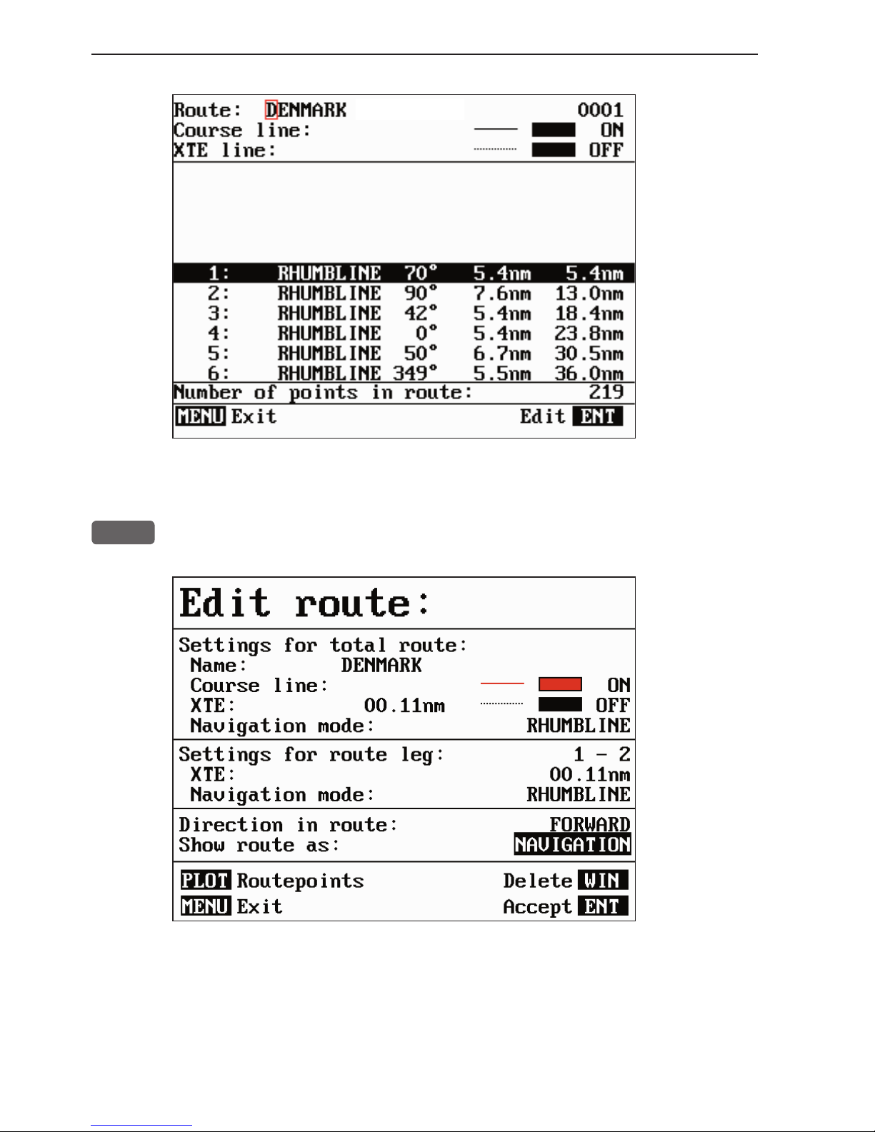
Chapter 7-4 CP44/54 Waypoint / route menu
This display provides information on course line, XTE line, route
legs, routepoints etc.
ENT
Call up the Edit route display - if you wish to make any changes.
Setting the Course line to OFF in this display will make the route
invisible on the screen. Put it back on the screen by setting it ON
again. The course line and XTE line can be changed in color - there
are a total of 15 colors to choose from together with 9 different line
types.
Page 87
CP44/54 Waypoint / route menu Chapter 7-5
If the XTE distance is not the same in all legs, the value will be *.*
instead of the 00.10nm. Navigation mode can be either RHUMBLINE or GREAT CIRCLE, or... if not set to the same in all legs in a
route, the mode will be: COMPOSITE.
Direction in route can be set to either FORWARD or REVERSE
direction.
Show route as can be set to either NAVIGATION for navigational
data in the route display (example on the previous page), or POINTS
for a list of routepoints together with the position in lat/long and the
XTE limit of each point.
Place the cursor on the function you wish to change
0-9
Key in new figures, and...
+/-
toggle between available values
- if no more alterations are required, go to [ENT], or you can insert/
remove routepoints from the route by entering a new display:
PLOT
Open for the function: Remove/insert routepoints
+/-
Existing routepoints can be removed, by using the +/- keys to high-
CLR
light the routepoint you wish to remove, and press [CLR]
New routepoints can be added to the route by using the cursor to go
up/down in the WP list to select the position you wish to add to the
route, then...
+/-
By means of the +/- keys highlight the routepoint where you wish the
PLOT
new position should be placed in the route, and press [PLOT]
- the last point in the RtePt panel is empty, and as such will allow
you to enter a new final routepoint.
ENT
Confirm modification of route and return to the Edit display
- or abandon modification by pressing [MENU]
ENT
Confirm editing
MENU
Return to route list
Page 88
Chapter 7-6 CP44/54 Waypoint / route menu
7.2.1 Delete route via menu
MENU
Call up the menu bar, and...
5,2
load route list
+/-
Select the route you wish to delete
ENT
Call up the route details on highlighted route
ENT
Open for editing
WIN
Delete route
CLR
Confirm that you want to delete the selected route, if not sure: press
[MENU] to exit the display without having made any changes.
Edit routes directly on the chart via info windows, refer to section
3.4.4 and 3.4.5.
7.2.2 Make new route from WP list
When you have a number of waypoints stored in the WP list which
would be convenient to link together as a route it is easily done via
the route list.
MENU
Call up the menu bar, and...
5,2
load route list
CLR
Make new route from WP list
Use the cursor to go up/down in the WP list to select the position you
wish to add to the route, then...
+/-
By means of the +/- keys you can control where the highlighted posi-
PLOT
tion is placed in the route, press [PLOT]
- the last point in the RtePt panel is empty, and as such will allow
you to enter a new final routepoint. Once a WP position is transferred to the routepoint section, there is no longer any connection
between the position and the waypoint in the WP list.
Select the next position and press [PLOT]. Continue in this manner
until the route is completed. In case you make a wrong plot, you can
delete the routepoint by highlighting the RtePt number by means of
Page 89

CP44/54 Waypoint / route menu Chapter 7-7
the +/- keys and then press [CLR] to remove the point from the route.
Display example:
ENT
Save the route with [ENT] and go to the Edit display
- or leave the function with [MENU] to abandon the route.
In the Edit route display you can set up the route preferences you
need and also change the name of the route.
Place the cursor on the function you wish to change
0-9
Key in new figures, and...
+/-
toggle between available values
ENT
Confirm editing
MENU
Return to route list
Page 90

Chapter 7-8 CP44/54 Waypoint / route menu
7.3 Route calculation
To stay well informed during navigation, the Route calculation
display will provide information on how long it takes to go from one
point to another, total distance, arrival time etc.
MENU
Call up the menu bar, and...
5,3
load route calculation display
+/-
Toggle between available routes in the memory
Go to Routepoint A, and...
0-9
Select the first routepoint (A) from where you wish to start the calcu-
lation in the route, and then select the second point (B)
Present speed is automatically used for calculating the arrival time,
but if required, an alternative speed can be inserted:
ENT
Open for change
0-9
Key in a new speed value
+/-
Toggle bet ween AUTO and MANUAL
ENT
Confirm entry
Page 91

CP44/54 Waypoint / route menu Chapter 7-9
7.4 Lines stored in the memory
The line list will keep a record of all the saved lines in the system. It
will provide information on number of line sections in line etc.
‘Lines’ are used for defining a certain area on the chart e.g. a fishing
ground, a shipwreck, large rocks, restricted areas etc., or defining a
channel to sail through narrow passages, making your own coast line
or for whatever reason you could use a drawing on the chart.
To draw new lines you need a chart in the active window, place the
cursor where you wish to start the line, and press [PLOT]. Then
follow the instructions in the info windows. Refer to section 3.4.9.
Lines can also be edited directly on the chart via info windows, refer
to section 3.4.4 and 3.4.5.
MENU
Call up the menu bar, and...
5,4
load line list display
- only plotted lines saved in the memory can be called forward.
This display
indicates
how many
line sections
are used for
the drawing.
+/-
Toggle through the stored lines with the +/- keys, or...
Leaf through the line points by moving cursor up/down
ENT
Call up the Edit line display - if you wish to make changes.
Page 92

Chapter 7-10 CP44/54 Waypoint / route menu
Turning “Line” OFF will make the line drawing invisible on the
screen. Put it back on the screen by turning it ON again.
Place the cursor on the function you wish to change i.e. name, line
type or color
+/-
Toggle between available values
ENT
Confirm entry
7.4.1 Delete lines via menu
MENU
Call up the menu bar, and...
5,4
load line list
+/-
Select the line you wish to delete
ENT
Open for editing
WIN
Delete line
CLR
Confirm that you want to delete the selected line, if not sure: press
[MENU] to exit the display without having made any changes.
Edit lines directly on the chart via info windows, refer to section
3.4.4 and 3.4.5.
Page 93

CP44/54 Waypoint / route menu Chapter 7-11
7.5 Start / stop track
The track function will provide a track trailing the movement of your
ship. As default from the factory, the first track is stored as TRACK
1, the next as TRACK 2 etc.
To st a rt t r ack func t ion:
TRACK
Load Start track pop-up window
If you wish to change the default values:
Move cursor to where you wish to make a change
+/-
Toggle between available values, or...
0-9
key in new values
ENT
Start track
Name of track can be altered (max. 25 characters).
Display track can be set ON and OFF, where OFF will make it
invisible on the screen. Turn ON to put it back on the screen.
Update of the track can be performed by distance in nautical miles,
or by time interval.
Page 94

Chapter 7-12 CP44/54 Waypoint / route menu
Ty pe of track line i.e. full, dotted, etc. has 9 different types to
choose from in 15 different colors.
To sto p track:
TRACK
Load Stop track pop-up window
ENT
Stop the highlighted track
7.6 Tracks stored in the memory
All tracks (of more than 1 trackpoint) will automatically be stored
in the memory. To see which tracks are registered, you can scroll
through the list by:
MENU
Call up the menu bar, and...
5,5
load “Tracks” in active window
A-Z
Select name of track
- or if a number is included in the track name, place cursor on the
number, and...
+/-
Toggle up/down in track numbers
ENT
Open for change
Page 95

CP44/54 Waypoint / route menu Chapter 7-13
“Display track” can be set ON/OFF, where OFF will make it invisible on the screen. Turn ON to put it back on the screen.
+/-
Toggle between available values
ENT
Confirm changes
7.6.1 Delete tracks via menu
MENU
Call up the menu bar, and...
5,5
load track display
+/-
Select the track you wish to delete
ENT
Open for editing
WIN
Delete track
CLR
Confirm that you want to delete the selected track, if not sure: press
[MENU] to exit the display without having made any changes.
Edit tracks directly on the chart via info windows, refer to section
3.4.6.
Page 96
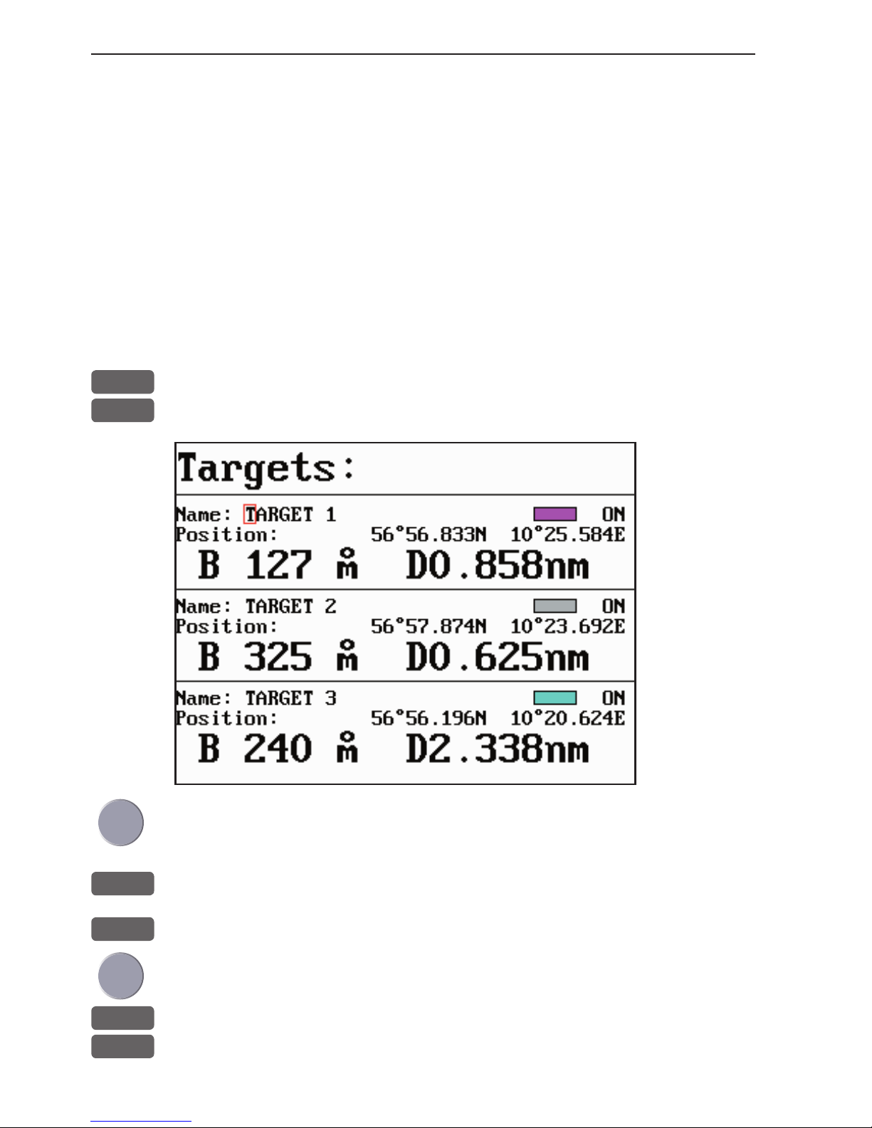
Chapter 7-14 CP44/54 Waypoint / route menu
7.7 Targets stored in the memory
The CPXX can display the bearing and distance of up to three
targets at a time in relation to the vessel e.g. harbors or important
navigational points. A target is a fixed point on the chart which can
be plotted by the cursor or from the ship’s position - refer to section
3.4.9, or keyed in via the keypad - refer to section 3.4.7.
Set up targets
The plotted target position is automatically preset to actual position
of ship, or to cursor position when the chart display is active and the
cursor is on - see INFO windows, section 3.4.7.
MENU
Call up the menu bar, and...
5,6
load target display
Make the
target invisible on the
screen by
turning it
OFF.
Put it back
on the screen
by turning it
ON again.
Select the target you wish to change or replace with a different
target by moving the cursor up/down
+/-
Leaf through the targets in the memory
ENT
Open for change, and...
Place cursor where you wish to make a change i.e. name, color etc.
A-Z
Key in new values, alphabetical or
0-9
numerical
Page 97
CP44/54 Waypoint / route menu Chapter 7-15
+/-
Toggle between available values
ENT
Confirm entry
7.7.1 Delete target via menu
MENU
Call up the menu bar, and...
5,6
load target display
+/-
Select the target you wish to delete
ENT
Open for editing
WIN
Delete target
CLR
Confirm that you want to delete the selected target, if not sure: press
[MENU] to exit the display without having made any changes.
Edit targets directly on the chart via info windows, refer to section
3.4.7.
7.8 MOB data
MENU
Call up the menu bar, and...
5,7
load MOB data display
MAN OVERBOARD
DATE 12-02-2003
TIME 14:23:34
MOB 56°52.489N
POS 009°50.305E
The MOB display will provide information of the last activated MOB position.
To delete a MOB track from the memory, see section 3.4.6.
Page 98

Chapter 7-16 CP44/54 Waypoint / route menu
7.9 Data transfer via DataCard or disc
Data transfer to and from external memory can be performed via
Simrad DataCard, or with a Simrad TL50 Turbo Loader via an ordinary 1.44Mb disc.
DataCards and TL50 Turbo Loader are optional equipment available
from your local Simrad dealer.
How to perform data transfers via TL50 (including data from Shipmate RS2500 Trackplotter) is described in the TL50 manual.
Use the Simrad DataCard or TL50 Turbo Loader to make backup
files of all the user data you have created plus the current setups
in the internal memory of the unit. Do it whenever you have added
important data, or when you wish to transfer routes and waypoints,
etc. to another compatible unit. The storage capacity of the DataCard/TL50 disc is divided into two databanks of each 450 Kb, meaning that the entire internal memory can be stored in one databank.
External memory with data transfer via DataCard:
MENU
Call up the menu bar, and...
5,8
load the Data transfer window
Data transfer
1
DataCard upper drawer
3
DataCard lower drawer
7
NMEA connection - see section 7.10
MENU
Exit
1
Select the drawer where you have inserted the DataCard e.g. [1]:
DataCard upper drawer
1
DataCard status
3
Save on DataCard
9
Load from DataCard
MENU
Exit
Page 99

CP44/54 Waypoint / route menu Chapter 7-17
DataCard status
1
Press [1] to find out what data (if any) is stored on the DataCard
The capacity is divided into two databanks: DATABANK 1 and 2
which can hold approx. 2 x 450 Kb data. Toggle between the two
databanks with the +/- keys.
Save on DataCard
3
Press [3] to call up a new INFO window where you can see which
data will be transferred i.e. routes, waypoints, etc. and how much
space it will take up in bytes + percentage of max. storage capacity.
The actual date and time will be saved with the data transfer.
+/-
Use the +/- keys to toggle between DATABANK 1 and 2
A-B
Use the alphanumeric keys to add a name to the data in the selected
databank
Use the cursor key to go to the ‘Ac t io n’ column to decide which
action you want taken for each mentioned category of data (toggle
with +/- keys) - see section 7.9.1.
If you choose to MERGE the data already stored on the DataCard
with the data coming from the Internal memory, the bottom line in
the window will ask you to press [ENT] to: Calculate databank after
merge.
ENT
Press [ENT] to activate ‘Save selected data on DataCard’
You will now receive a warning about which data on the DataCard,
in the selected databank, will be overwritten. Press [ENT] to accept.
After the data has been transferred, you will receive a status report.
MENU
Press [MENU] to exit function
Load from DataCard
9
Press [9] to call up a new INFO window where you can see which
data is stored in Databank 1 or 2 on the DataCard - see display
example next page.
+/-
Use the +/- keys to toggle between DATABANK 1 and 2
Page 100

Chapter 7-18 CP44/54 Waypoint / route menu
User data generated by other chartplotter models e.g. CE33/40/42/52,
CP33/40/42/52, CA40/42/52, CR40/42/52 can all be transferred to a
CP44/54 unit via the Data transfer system.
However, it is not immediately accessible to transfer data via DataCard from the new model CP44/54 to the older model CP42, etc., as
this would require an update of the CP42.
- For more information, please contact an authorized Simrad dealer.
Load from DataCard: DATABANK-1
Data generated by: Simrad CP44
Used internal memory: 193393 bytes = 42%
Used DataCard memory: 2677 bytes = 1%
Used internal memory after operation: 191400 bytes = 42%
Date saved: 15-02-2003
Time saved: 19:43:00
Name:
Data type
Internal
Amount Bytes
DataCard
Amount Bytes
Internal
after
Amount Bytes
Action
Marks/waypoints:
Lines:
Routes:
Targets:
Tracks:
Setup:
9 244
0 0
1 168
0 0
8 190480
1 2501
11 256
2 168
4 408
1 100
0 0
1 1745
9 244
2 168
4 408
1 100
8 190480
0 0
NO
OVERWRITE
OVERWRITE
OVERWRITE
NO
NO
MENU
Exit Load selected data from DataCard
ENT
Use the cursor key to go to the ‘A ct i o n’ column to decide which
action you want taken for each mentioned category of data (toggle
with +/- keys) - see section 7.9.1.
If you choose to MERGE the data already stored in the Internal
memory with the data coming from the DataCard, the bottom line in
the window will ask you to press [ENT] to: Calculate databank after
merge.
ENT
Press [ENT] to activate ‘Load selected data from DataCard’
You will now receive a warning about which data in the internal
memory of the unit will be overwritten. Press [ENT] to accept.
After the data has been transferred, you will receive a status report.
 Loading...