

Page 1

M A N U A L
Simrad CA34/44/54
MultiRadar
183-3405-102 English 05082.20
Note!
Insert or remove C-MAP cartridges ONLY through SETUP menu or when
unit is off. All electronic navigation equipment is subject to external factors
beyond the control of the manufacturer. Therefore such equipment must be
regarded as an aid to navigation. The prudent navigator will, for that reason,
never rely on a single source for position fixing and navigation.
Page 2
MOB ‘MAN OVERBOARD’ function
MOB
In case someone falls overboard, press the [MOB] key and hold for 2
seconds (or activate an external MOB switch - hold for 5 seconds).
CLR
Press [CLR] to confirm and reset the alarm if activated by mistake.
Before pressing [ENT] to start MOB navigation:
• Reduce speed.
• Turn off Autopilot.
ENT
Press [ENT] to start MOB navigation with all relevant data available
for an efficient rescue operation and a precise track record of the
vessel’s movements.
Window
1
Window
2
Screen layout default after activating MOB.
Window
3
Window 1: Data display will provide information of: Course, Bear-
ing and Distance to MOB position, time elapsed since the incident
occurred - first in seconds and then in minutes - if “*” is shown
instead of numbers of minutes, means that the elapsed time has
exceeded 9999 minutes. The two lines after the TIME shows the
MOB position in Lat/Long.
Window 2: The chart display will provide a graphical impression of
a man
floating in the water at the MOB position together with a
course line from actual position to the incident.
Window 3: Data display will provide information of: Date, time and
position of MOB incident.
To t ur n MOB nav ig at ion of f:
Press [GOTO], [3].
To recall the last registered MOB position, see section 8.8.
Page 3

CA34/44/54 MultiRadar Table of contents
MOB ‘MAN OVERBOARD’ function.............................back of front cover
Chapter 1 Introduction and safety summary
1.1 Introduction and system familiarization ...................................... 1-1
1.2 Safety summary ........................................................................... 1-2
1.3 How to get started ........................................................................ 1-3
1.3.1 Dedicated function keys...............................................................1-4
1.3.2 Radar and radar functions............................................................ 1-6
1.3.3 Chart and chart functions............................................................. 1-6
1.3.4 Echosounder / Fishfinder ............................................................1-10
Chapter 2 Fundamentals and initial start-up
2.1 Fundamentals of the display and page system ............................. 2-1
2.1.1 Example of how to exchange a page in the PAGE system ........... 2-2
2.1.2 Example of how to select a new display in a custom screen........ 2-2
2.2 Key functions ............................................................................... 2-3
2.3 Menu bar....................................................................................... 2-5
2.4 Menu layout..................................................................................2-6
2.5 Choice of symbols ........................................................................ 2-7
2.6 Naming of routes, points etc......................................................... 2-7
2.7 Initial start-up............................................................................... 2-7
2.8 Turn power on............................................................................... 2-9
2.9 Turn power off.............................................................................. 2-9
Chapter 3 Radar menu
3. Radar operation ............................................................................ 3-1
3.1 Radar picture ................................................................................ 3-1
3.1.1 Orientation.................................................................................... 3-2
3.1.2 Effects of ship’s movement........................................................... 3-2
3.1.3 Environment effects ..................................................................... 3-3
3.1.4 Navigational echoes......................................................................3-4
3.1.5 Racon (Radar Beacon) .................................................................3-4
3.1.6 Sea return ..................................................................................... 3-5
3.1.7 Storm and rain squall returns....................................................... 3-5
3.1.8 Blind sectors or shadow effect ..................................................... 3-5
3.1.9 Side lobes...................................................................................... 3-6
3.1.10 Radar interference........................................................................3-6
3.1.11 False echoes.................................................................................. 3-7
3.2 Radar menu ..................................................................................3-8
3.2.1 Shortcut to the pages in the radar-series ...................................... 3-9
3.2.2 Initial radar display setup............................................................. 3-9
3.2.3 Start transmission....................................................................... 3-10
3.2.4
Shut down procedure for the radar function, or back to ‘Standby’..3-10
Page 4

Table of contents CA34/44/54 MultiRadar
3.2.5 Standard radar display...................................................................... 3-11
3.2.6 Radar quick menu............................................................................. 3-17
3.2.7 RadarChart overlay...........................................................................3-19
3.2.8 Dual radar display ............................................................................3-24
3.2.9 Radar & Chart display......................................................................3-25
3.2.10 General features for the radar operation ..........................................3-26
3.3 Demo mode.......................................................................................3-28
Chapter 4 Chart menu and INFO windows
4. Chart menu................................................................................... 4-1
4.1 Shortcut to the pages in the chart-series ...................................... 4-1
4.1.1 Data field on chart........................................................................ 4-2
4.1.2 Ship symbol.................................................................................. 4-3
4.1.3 Cursor function ............................................................................ 4-3
4.1.4 Range or zoom function...............................................................4-4
4.2 Dual Chart display........................................................................4-5
4.3 Chart split screens ........................................................................4-6
4.4 Chart quick menu ......................................................................... 4-7
4.4.1 Cursor inactive ............................................................................. 4-7
4.4.2 Cursor active but not placed on any object or data ......................4-8
4.4.3 Cursor placed on waypoint........................................................... 4-9
4.4.4 Cursor placed on route leg or line section.................................. 4-10
4.4.5 Cursor placed on routepoint or linepoint ....................................4-11
4.4.6 Cursor placed on trackpoint ....................................................... 4-12
4.4.7 Cursor placed on target .............................................................. 4-13
4.4.8 GOTO menu ............................................................................... 4-14
4.4.9 PLOT menu ................................................................................ 4-15
4.5 Chart setup ................................................................................. 4-17
4.5.1 Display modes in the chart setup ............................................... 4-18
4.5.2 Description of chart features...................................................... 4-21
Chapter 5 Echo menu
5. Echosounder operation................................................................. 5-1
5.1 Echo menu.................................................................................... 5-2
5.2 Shortcut to the pages in the echo-series....................................... 5-2
5.3 Standard echo display................................................................... 5-3
5.4 Variable range marker ..................................................................5-4
5.5 Echo quick menu .......................................................................... 5-5
5.6 Plot waypoint or event mark via PLOT menu..............................5-6
5.7 Presentation setup......................................................................... 5-7
5.8 How the echosounder works ...................................................... 5-10
5.9 Transducer beamwidth ................................................................5-11
5.10 Effects of the vessel’s speed ....................................................... 5-12
Page 5

CA34/44/54 MultiRadar Table of contents
Chapter 6 Pilot menu & navigation examples
6. Pilot menu..................................................................................... 6-1
6.1 Shortcut to the pages in the pilot-series .......................................6-1
6.2 Highway display and Navigation setup ........................................ 6-3
6.2.1 Highway display when navigation mode is active........................6-5
6.3 Position display.............................................................................6-6
6.4 Dual speed display (trawling speed display) ................................6-9
6.5 ETA & AVN ............................................................................... 6-10
6.6 Trim & Highway display............................................................ 6-11
6.7 Set & Drift display ..................................................................... 6-12
6.8 Pilot split screens........................................................................ 6-13
6.9 Navigation examples .................................................................. 6-14
6.9.1 Cursor navigation ....................................................................... 6-14
6.9.2 Waypoint navigation................................................................... 6-15
6.9.3 Route navigation......................................................................... 6-16
6.9.4 Track navigation......................................................................... 6-17
6.10 Anchor guard.............................................................................. 6-19
6.11 MOB alarm and navigation ........................................................ 6-19
Chapter 7 Miscellaneous menu
7. Miscellaneous menu..................................................................... 7-1
7.1 Wind display................................................................................. 7-1
7.2 Speed diagram.............................................................................. 7-3
7.3 Decca lanes................................................................................... 7-5
7.4 Loran C......................................................................................... 7-6
7.5 Satellite status............................................................................... 7-7
7.6 DGPS information........................................................................ 7-9
7.7 SDGPS information.....................................................................7-11
7.7.1 Satellites in SDGPS system.........................................................7-13
7.8 DSC VHF alarm..........................................................................7-14
7.9 Depth and temperature diagram..................................................7-15
Chapter 8 Waypoint / route menu
8. Waypoint / route menu ................................................................. 8-1
8.1 Waypoints stored in the memory ................................................. 8-1
8.1.1 Delete waypoints via menu .......................................................... 8-2
8.2 Routes stored in the memory........................................................ 8-3
8.2.1 Delete route via menu...................................................................8-6
8.2.2 Make new route from WP list ...................................................... 8-6
8.3 Route calculation..........................................................................8-8
8.4 Lines stored in the memory.......................................................... 8-9
8.4.1 Delete lines via menu ................................................................. 8-10
8.5 Start / stop track ..........................................................................8-11
8.6 Tracks stored in the memory...................................................... 8-12
Page 6

Table of contents CA34/44/54 MultiRadar
8.6.1 Delete tracks via menu ............................................................... 8-13
8.7 Targets stored in the memory......................................................8-14
8.7.1 Delete target via menu................................................................ 8-15
8.8 MOB data ................................................................................... 8-15
8.9 Data transfer via DataCard or disc..............................................8-16
8.9.1 List of criteria for data transfer in the Action column ............... 8-19
8.10 Data transfer via PC interface .................................................... 8-20
Chapter 9 Setup menu
9. Setup menu................................................................................... 9-1
9.1 Radar setup................................................................................... 9-1
9.2 C-MAP cartridges........................................................................ 9-5
9.3 Echosounder setup........................................................................9-6
9.4 Pilot / Position setup..................................................................... 9-9
9.5 Speed alarm, units & language ...................................................9-11
9.6 Interface setup............................................................................ 9-13
9.6.1 Description of sentences............................................................. 9-23
9.7 Palette setup................................................................................ 9-25
9.8 Factory settings .......................................................................... 9-26
9.9 QuickGuide ................................................................................ 9-28
Chapter 10 Troubleshooting, Maintenance and Service
10.1 Troubleshooting.......................................................................... 10-1
10.2 Preventive maintenance.............................................................. 10-3
10.3 Repair and service...................................................................... 10-3
10.4 Specifications ............................................................................. 10-4
Appendix A Glossary of terms...................................................................A-1
Appendix B List of datum ..........................................................................B-1
Appendix C C-MAP attributes...................................................................C-1
Index .............................................................................. end of manual
Declarations of conformity....................................................... end of manual
International warranty .............................................................. end of manual
List of Simrad distributors........................................................ end of manual
Page 7

CA34/44/54 Introduction and safety summary Chapter 1-1
1.1 Introduction and system familiarization
Congratulations on your purchase of SIMRAD CA34/44/54 MultiRadar - a
combination of the latest GPS and SDGPS receiver technology and optional
built-in differential receiver for accurate positioning, plus: detailed cartography and high performance radar and echosounder technology; all in a unique
slim-line design with a bright 7” TFT (CA34), 10” ATFT/TFT (CA44) or 15”
TFT (CA54) color display.
The radar system with RadarChart overlay, dual EBL and VRM markers,
direct Quick-range keys, off-center mode, etc. together with Dual Radar feature ... two radar displays in one screen, one for short range and one for long
distance observations.
The electronic chart system includes a built-in world chart for rough planning and overview. The choice of chart system best suitable for the CA34/44/
54 was carefully singled out to be the C-MAP NT+ mini cards. The optional
C-MAP charts are available world-wide at your local Simrad dealer.
The echosounder system with selectable frequencies will provide an impres-
sion of Bottom expansion, VRM expansion, Shift, A-scope and White line.
The Global Positioning System is at this time and age the most common
system used for navigation and positioning all over the world. Not only for
maritime use, but also for land-based applications and aviation. The satellite-based system has been developed and is operated by the US Department
of Defense in order to provide an accurate and reliable service, which include
a 24-hour global coverage. The GPS system consists of approx. 24 satellites
which orbit around the Earth at an altitude of approx. 20,200 km.
The satellites transmit perfectly synchronized data. However, depending on
the position, the signals will reach the receiver at a slightly different time. By
adding the measured time difference to the known position of the satellites it
is possible to calculate the ship’s position to within a few meters.
The SimNet data and control network provides high speed data transfer and
control between Simrad products that are integrated as a total navigation,
steering and communication system on board.
DS34/44/54 Dual Station for the CA34/44/54 is available with a bright 7”
TFT, 10” ATFT/TFT or 15” TFT color display. The main unit and the dual station are identical in design and operation.
How to use this manual? This manual is written for the products: CA34,
CA44 and CA54, which mainly share the same type of software. From hereon,
these models will be referred to as: CAXX.
Page 8

Chapter 1-2 CA34/44/54 Introduction and safety summary
It is a good idea if you make yourself familiar with the key functions, menu
structure and rotation of pages (screens) described in chapter 2 before you
start out, and then proceed with section 2.7 Initial start-up. For quick location
of a certain term, please check the “Glossary of terms” and the “Index” at the
back of the manual. Also, “How to get started” further on in this chapter will
give you a quick introduction to some of the features you have access to in
your new MultiRadar.
The display examples shown in this manual are not always an exact copy of
what you will see on the screen, as the presentation depends on your system
configuration and choices of setup. How to interpret special marked key symbols etc. in the manual:
+/-
Either the + (plus) or - (minus) key may be applied.
Emphasizes important points.
1,3
Indicates that you should press the keys [1] and [3] to obtain what is
written in italic next to the key.
1.2 Safety summary
Precaution: Do not open the equipment, only qualified persons should work
inside the equipment. If the glass in the screen breaks, be carefull not to get
cut on the sharp edges of the glass pieces.
The lifetime of the internal battery is minimum 5 years. If not exchanged
before it goes flat, all data in the unit’s memory will be lost. We strongly
recommend that you frequently store your data on a Simrad DataCard. For
exchange of battery, call your local Simrad workshop.
Power source, fuse and power cable: Check that the DC power supplied to
the unit is within the range of 10 to 32 volts. Note that the appropriate fuse
must be employed (see the fuse rating in section 10.4 Specifications). Ensure
that the power cord is firmly attached.
Grounding: To reduce electrical interference and risk of electrical shock,
properly ground the unit to the ship’s ground using the ground screw at the
rear of the unit. Good grounding should also be exercised for connected equipment, refer to separate Installation manual.
Cleaning:
Do not use any kind of strong solvents e.g. spirit, alcohol, gasoline or oils.
Software: The software version of the main unit (see start-up display) should
always be informed in a service situation, or when ordering a Dual Station.
Page 9
Automatic input source setup
Interface has not been set up!
To start automatic input
source setup, make sure that
all connected products are
turned ON, and press ENT.
Start
ENT
∆
∆
CA34/44/54 Introduction and safety summary Chapter 1-3
1.3 How to get started
When starting up for the very first time, the first time after loading
a new software or after a master reset: Make sure that all hardware
installation and electrical connections are completed in accordance
to the installation instructions.
PWR
Press and hold the [PWR] key until you have a picture on the screen
The system will perform a software update and check for communication activity. When finished, a new start-up window will be
presented on the screen:
After making sure that all connected products are turned ON:
ENT
Press [ENT] to start automatic input source setup, - if a new product
is connected later on, refer to section 9.6 Interface setup.
New window: Automatic input source setup listing Data type, Group
and Source of connected units.
ENT
Press [ENT] to continue
PAGE
Press [PAGE] to scroll through a quick guide which informs of the
use of the keys and where you can enter owner’s setup, etc.
- the quick guide is also accessible via [MENU], [7], [5].
ENT
Press [ENT] when ready to assume normal operation
- go to [MENU], [7], [2] if you wish to make adjustments to the
interface setup.
Page 10
Chapter 1-4 CA34/44/54 Introduction and safety summary
Heading is only available if a compass was detected at start-up.
Your present position will automatically be updated within a few minutes. When ready, the ship symbol on the chart will flash, the position
coordinates will stop flashing, and the *** will be replaced by actual
course and speed figures.
1.3.1 Dedicated function keys
RADAR
Short press will toggle overlay on/off:
The toggle function will require:
1. Valid position.
2. Valid heading from compass
3. Orientation set to NU
- refer to section 3.2.7.
Radar display RadarChart overlay
RADAR
Long press will toggle between:
Radar display Dual Radar Radar & Chart Custom screen
CHART
Short press will toggle between:
Chart + data field placed either at the right side or at the top, and echo data.
CHART
Long press will toggle between:
Chart display Dual Chart Custom screen1 Custom screen2
Page 11
CA34/44/54 Introduction and safety summary Chapter 1-5
ECHO
Long press will toggle between:
Echo + A-scope Dual frequencies Custom screen1 Custom screen2
(CA44/54)
PILOT
Short press will toggle between:
Highway Position Dual Speed Set & Drift
When navigation mode is active,
these two displays will be included:
ETA & AVN Trim & Highway
PILOT
Long press will toggle between:
Highway Custom screen1 Custom screen2
PAGE
Short press will toggle between active pages under the main function
keys. Long press will start a rotation of the 4 pages (section 2.1).
Page 12

Chapter 1-6 CA34/44/54 Introduction and safety summary
1.3.2 Radar and radar functions
RADAR
Press the [RADAR] key to call up a radar display. Press again to
toggle between the radar shortcut series
- see display examples in section 1.3.1.
To start the radar
1. Press [ENT], [RADAR] to initiate a warming up period of two minutes
(countdown of 120 seconds), and then the radar will go in Standby mode.
2. Press [ENT], [GOTO] to start transmission.
Select and adjust radar range
Press one of the numeric keys 1 - 9 to select a fixed range. Key 9 will select
the largest range and key 1 the smallest.
ENT
Press [ENT] to call up the Radar quick menu with access to e.g.
Overlay Chart, Overlay User Data, activate EBL-VRM cursors, start
and stop radar transmission, etc.
EBL
Toggle the EBL-VRM1 cursors on/off directly from the [EBL] key.
CLR
Turn off cursor. Long press on [CLR] will turn off all cursors on the
radar screen.
ADJ
The [ADJ] key will open for adjustment of the radar parameters.
Use the cursor or the [ADJ] key to move around in the control panel;
toggle between available values with the +/- keys or enter new values
with the numeric keys. Press [ENT] to exit control panel.
In the Dual Radar display: after pressing the [ADJ] key to access the
control panel, only half of the parameters will be visible. By pressing
[ADJ] again will toggle between the 1st and 2nd half of the control
panel.
1.3.3 Chart and chart functions
CHART
Press the [CHART] key to call up a chart display. Press again to
toggle between the chart shortcut series
- see chart examples in section 1.3.1.
C-MAP cartridges (standby)
Press [MENU], [7], [CHART] whenever inserting or removing a C-MAP card.
Page 13

CA34/44/54 Introduction and safety summary Chapter 1-7
Select and adjust chart range/scale
Press one of the numeric keys 1 - 9 to select a fixed range (and chart level).
Key 9 will select the largest range and key 1 the smallest. Use the +/- keys to
adjust range in smaller steps.
Chart cursor and info windows
Press the cursor key to activate the cross hair cursor on the chart. Place the
cursor on a C-MAP object e.g. a buoy or light to call up a small data window
with details on the object. The data window will stay on screen for about 10
seconds or till cursor is moved. Press [ENT], [2] to access further details on
C-MAP objects or user data i.e. waypoints, routes, etc.
Press [ENT], [5] to lock cursors in Dual Chart screen and [ENT], [5] to
release cursors again. Press [CLR] to switch off cursor function. The ship
symbol will now automatically ‘home’ and stay on screen.
Find nearest tide station and port services
1. Press [ENT], [3]
2. Move cursor up/down to select e.g. the Port/Marina symbol
3. Locate alternative port with the +/- keys, and press [ENT]
4. Press [ENT], [2] for more details on the facilities at the selected port.
Navigate to cursor (point and go)
1. Move the cursor to where you wish to go (first point)
2. Press [GOTO]
3. Press [1] to start navigation.
You can now move the cursor to the next point and when ready to change leg,
just press [GOTO], [2].
How to plot or insert waypoints and marks
• With cursor OFF (press [CLR])
Press [PLOT] and choose from:
[PLOT] Plot ship’s position as mark.
[1] Insert ship’s position. You can change the lat/lon figures, the symbol
and the symbol’s size and color.
[3] Insert specific waypoint. Suggested name, symbol, etc. can be altered.
[6] Plot ship’s position as target.
• With cursor activated on the chart you also have access to:
[2] Plot waypoint - cursor position.
[6] Plot cursor position as target.
Page 14

Chapter 1-8 CA34/44/54 Introduction and safety summary
How to make a route on the chart
1. Place the cursor on the position for the first routepoint.
2. Press [PLOT], [4]: Make route.
3. Move cursor to next destination and press [PLOT] - (repeat).
4. Press [ENT] when ready to save the route. You can enter a new name for the
route, change type and color for the course line.
5. Press [ENT] to accept and save the route.
How to make a route from existing waypoints stored in the WP list
1. Press [MENU], [6], [2] to call up the route list.
2. Press [CLR] Make new route from WP list.
3. Move cursor up/down to select the WP position for the first routepoint, and
press [PLOT].
4. Repeat point 3 to add new WP positions to the route (the last routepoint in
the right column is always empty, allowing that a new final routepoint can
be added later on).
5. When the route is completed, press [ENT] to accept and go to Edit route.
6. In the Edit route display, you can give the route a new name, change type
and color for the course line, etc.
7. Press [ENT] to accept changes and save the route.
8. Press [MENU] to go to the route list, which will provide an overall view of
the total of routes stored in the CAXX.
How to edit a route - rubberbanding
• To move a point on the chart:
1. Place cursor on the point you wish to move.
2. Press [ENT], [1], [2].
3. Move cursor to new location.
4. Press [ENT] to complete.
• To insert a new point on the chart:
1. Place cursor on the leg where the new point is to be inserted.
2. Press [ENT], [1], [2].
3. Move cursor to where the new routepoint is to be placed.
4. Press [ENT] to complete.
How to start waypoint navigation (two ways)
• Place cursor on the symbol of the WP you wish to go to:
1. Press [GOTO], [2].
2. Press [ENT] to start navigation.
Page 15

CA34/44/54 Introduction and safety summary Chapter 1-9
• Without placing cursor on the symbol of the WP you wish to go to:
1. Press [GOTO], [2].
2. Use the +/- keys to select the WP you wish to go to.
3. Press [ENT] to start navigation.
How to start route navigation (two ways)
• Place cursor on the routepoint you wish to go to first:
1. Press [GOTO], [3].
2. Select direction in route: Forward or Reverse.
3. Press [ENT] to start navigation.
• Without placing cursor on the routepoint you wish to go to first:
1. Press [GOTO], [3].
2. Use the +/- keys to select the name of the route.
3. Use the cursor to go to routepoint number, and select which one you wish to
go to first by means of the +/- keys.
4. Select direction in route: Forward or Reverse.
5. Press [ENT] to start navigation.
Advance or stop navigation
• Press [GOTO], [1] to advance to next point in the route.
• Press [GOTO], [3] to stop navigation.
Start and stop track
1. Press [PLOT], [7] to call up ‘Start track’ window.
2. Before tracking is started, you can give the track a new name, make
changes to track interval, track line type and color.
3. Press [ENT] to start track.
4. When you wish to stop tracking, press [PLOT], [8], [ENT].
Page 16

Chapter 1-10 CA34/44/54 Introduction and safety summary
1.3.4 Echosounder / Fishfinder
ECHO
Press the [ECHO] key to call up an echosounder display. Press
again to toggle between the echo shortcut series
- see display examples in section 1.3.1.
Select and adjust echosounder range
Press one of the numeric keys 1 - 9 to select a fixed range. Key 9 will select
the largest range and key 1 the smallest. Use the +/- keys to adjust range in
smaller steps. Key 0 will select Auto Range.
A-scope - Press [ENT], [2] to toggle A-scope on/off. The strength of the
actual echo is indicated by both width and color intensity.
Change frequency - Press [ENT], [1] to toggle between e.g. 50 and 200 kHz.
Gain - Adjust gain with cursor left/right to just below the point where you
begin to see speckles of ‘noise’ on the screen.
Bottom lock display* - Press [ENT], [4] Bottom lock is a combination of
standard echo display and extended area around the bottom.
Zoom display* - Press [ENT], [5] The expansion is a combination of standard echo display and extended area around the VRM - Variable Range Marker.
Shift display* - Press [ENT], [6] when operating in deep waters.
Select the range for an expansion window. The expansion window can automatically follow a changing bottom or be set manually by the +/- keys.
*Return to standard echosounder display by pressing [ENT], [3].
Echo setup (presentation) - Press [ADJ] from echo display to access the
setup display for either 38 (CA44/54), 50 or 200 kHz. Press [ENT] to confirm
changes, or leave the setup without having made any changes by pressing
[MENU].
Echosounder setup - Press [MENU], [7], [ECHO] when you need to make
any general settings, selecting a transducer or selecting demo mode etc.
Transmit power off - Press [ENT], [ECHO] to stop transmission in order to
observe noise picked up by the transducer or to reduce power consumption.
Page 17
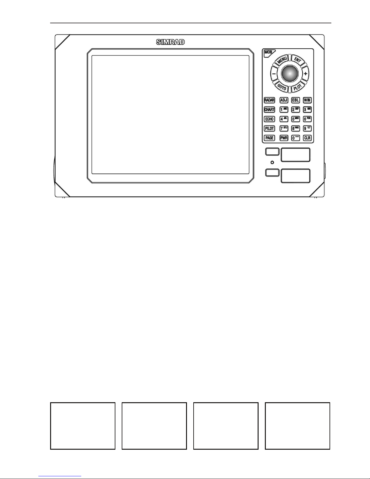
Chart with
data field
Echo display
with A-scope
Radar display Highway display
SIMRAD CA44
CA34/44/54 Fundamentals & initial start-up Chapter 2-1
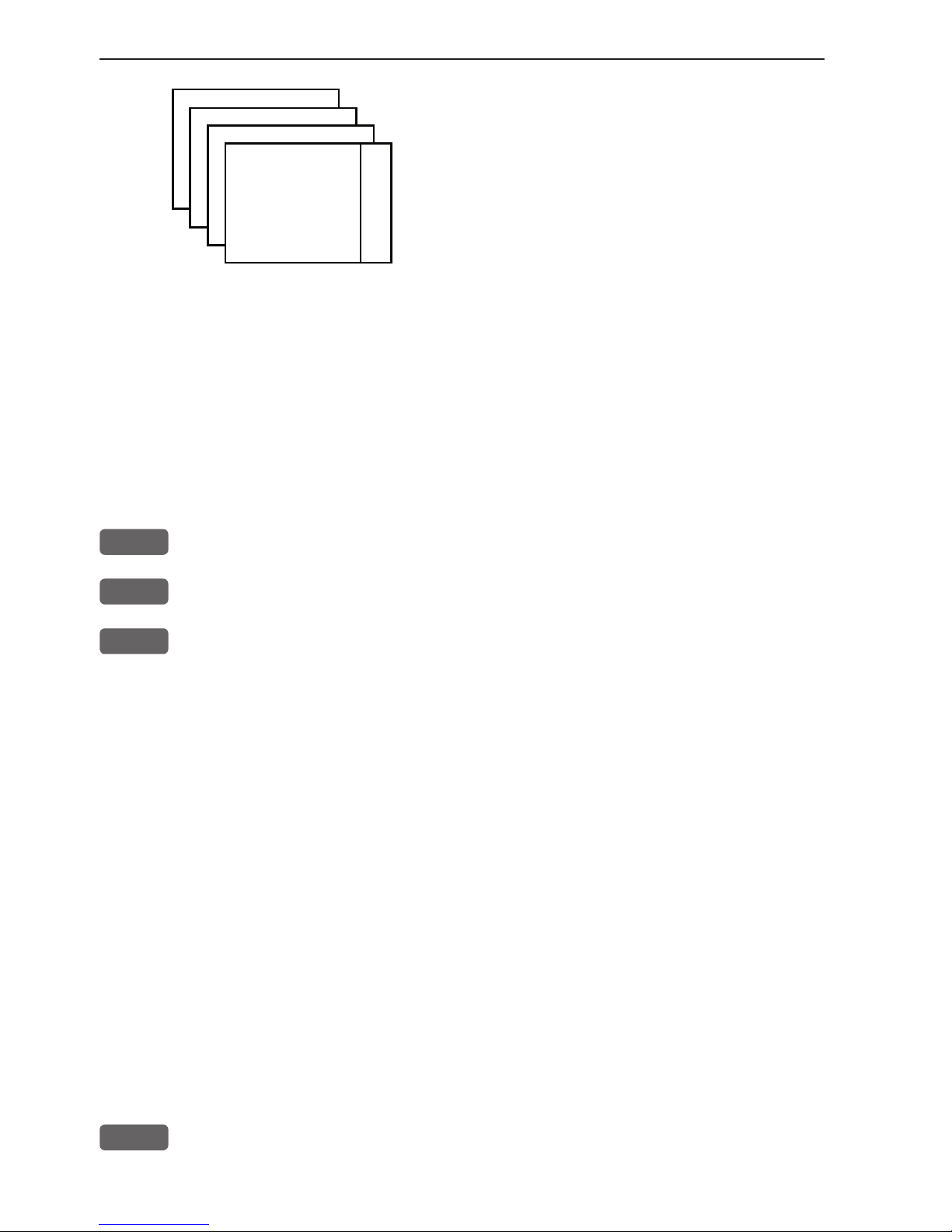
2.1 Fundamentals of the display and page system
The CA34/44/54 MultiRadar has a multi-function screen and data
presentation system with full screen and different types of split
screens. The series of pages under the function keys (situated in a
vertical row to the right of the display) will in most situations be sufficient information for the operator.
In split screens consisting of up to four displays, the active display
is indicated by a solid red frame. Use the [WIN] key to clockwise
toggle between which display on the screen is active. Only active
displays are operable.
The [PAGE] key differs from the other function keys. There are four
pages under the [PAGE] key which can be set up to the presentation
you prefer by exchanging an existing display in the PAGE system
with a new one selected from a function key or via the menu - see
next page. Single press on the [PAGE] key will toggle between the
active pages under the function keys e.g.:
Page 18
Chapter 2-2 CA34/44/54 Fundamentals & initial start-up
Long press on the [PAGE] key will start
a rotation of the four pages in intervals of
5 seconds (increase/decrease the time in
[MENU], [7], [1]). Press any key to stop
rotation.
2.1.1 Example of how to exchange a page in the PAGE system
The four pages in the PAGE system are collected from the RADAR,
CHART, ECHO and PILOT menus in the sequence of which the
function keys appear on the keypad ie. the first page is from the
RADAR function, the second page is from the CHART function, the
third page is from the ECHO function, and the fourth page is from
the PILOT function. This sequence can not be changed, only the
choice of display collected from each function can be changed e.g.:
PAGE
Press the [PAGE] key until the full screen Chart display appears
MENU
Call up the menu bar, and...
2,2
collect the Dual Chart display
- or you can toggle between the available displays in the CHART
function by pressing (long press) the [CHART] key repeatedly.
The same applies for the other three pages in the PAGE system ie.
press the [PAGE] key until a display from the RADAR, ECHO or
PILOT function appears and then collect a new display from the
appropriate menu.
The display sequence under the function keys is the same as the
display sequence in the matching menu.
2.1.2 Example of how to select a new display in a custom screen
In custom screens with multiple window combinations, all displays, which are not main function displays, are exchangeable. It is
also possible to change the right half of the screen from half screen
window to two quarter windows and vice versa. Example:
MENU
Call up the menu bar, and...
Page 19
CA34/44/54 Fundamentals & initial start-up Chapter 2-3
Highlight a function e.g. Route calculation in the WP/RTE menu.
WIN
Press [WIN] several times to check the screen image (situated to the
far right in the top line of the menu bar) which windows the function
can be placed into
ENT
Press [ENT] to enter the highlighted function into the highlighted
window
If the function text in the menu is red, the display will not be avail-
able for the selected window.
2.2 Key functions
Some of the key functions are general and can be applied at any
time, other key functions are related to a certain menu(s) and can
only be applied when in the appropriate menu.
MOB
Press for two seconds to activate the MOB - “Man overboard” function.
MENU
Turns the menu bar on/off. Exits any data display without taking any
action (except the radar function).
ENT
Confirms insertion and editing of data (except the radar function).
Calls up quick menus, and information on marks, waypoints, etc. on
chart together with several INFO windows from a chart display.
Moves cursor in data displays and charts + activates cursor on chart
and radar. Moves left/right/up/down in the menu system. Adjusts
gain (left/right), activates and moves VRM (up/down) in echo display.
+/-
Changes radar, chart or echosounder range i.e. + (plus) zooms out
for better overview (larger range) and - (minus) zooms in for greater
details (smaller range). Toggles between available values.
GOTO
Activates GOTO menu with choice of navigation modes, etc.
PLOT
Activates PLOT menu with choice of plotting and inserting way-
points, routes, lines etc. together with starting or stopping a track of
own ship.
Page 20

Chapter 2-4 CA34/44/54 Fundamentals & initial start-up
RADAR
Shortcut to Radar functions. Short press will toggle overlay on/off.
Long press will toggle between Radar display in full screen, Dual
Radar, Radar & Chart, and a custom screen.
CHART
Shortcut to Chart function. Short press will toggle between differ-
ent data fields on chart. Long press will toggle between Chart in full
screen, Dual Chart, and two custom screens.
ECHO
Shortcut to Echosounder functions. Long press will toggle between
Echo display in full screen with A-scope, Dual Frequency (CA44/
54), and two custom screens.
PILOT
Shortcut to Pilot displays. With navigation mode inactive: short
press will toggle between Highway, Position, Dual Speed and Set &
Drift displays. With navigation mode active: short press will toggle
between Highway, Position, Dual Speed, ETA & AVN, Trim &
Highway, and Set & Drift displays. Long press will toggle between
Pilot full screen and two custom screens.
PAGE
Toggles between active pages under the four main function keys
i.e. [RADAR], [CHART], [ECHO] and [PILOT]. Long press starts
automatic rotation of these pages. Press any key to stop rotation.
ADJ
Gives access to setup displays related to active display. Scrolls
through adjustable parameters.
EBL
Toggles EBL-VRM1 on/off. The Electronic Bearing Lines may be displayed in either degrees Relative “R” (to ship’s centerline) or True “T”
(Relative to north), depending on the selected orientation (HU or NU).
WIN
Toggles between active windows in split screen. The active window
will have a solid red frame. Only active windows are operable.
0-9
The alphanumeric keys inserts and selects data in data displays.
Keys 1-9 are also Quick-range keys, which each represent a fixed
radar, chart or echosounder range. Key 0 will center the cursor/ship
on the chart, activate auto range in sounder mode, and activate/
deactivate ‘off-center to cursor’ on the radar display.
CLR
Deletes data in enter or edit mode. Turns cursor off in active display.
Long press will turn off all active cursors on radar display.
From radar control menu: Returns Tune, Gain or Sea to AUTOmatic
mode, and clears the EBL and VRM readings.
Page 21
CA34/44/54 Fundamentals & initial start-up Chapter 2-5
PWR
Power on - hold key depressed till you have a picture on the screen.
Calls up a window where you can adjust the brightness in the screen,
background light in keypad, and select Daylight displays, Night
display or custom made color palettes. Hold two seconds to turn the
power off.
2.3 Menu bar
MENU
Toggle s the men u bar on/ off
To fit the complete menu bar across the screen, some of the menus
have been abbreviated. However, the last selected menu will be highlighted, and if it’s an abbreviation of the menu, then the complete
menu title is written above the menu bar.
MISCELLANEOUS
1
RADAR2CHART
3
ECHO
4
PILOT
5
MISC
6
WP/RTE
7
SETUP
1
Wind
2
Speed diagram, etc.
Having selected e.g. 5:MISC from the menu bar, its associated menus will
drop down. Key in the number next to the function you wish to call forward,
or use the cursor key to highlight the function and press [ENT].
If you want to switch to a different menu, use the cursor key left/right to move
to the adjacent menu.
Most functions in the menus are general, and can be called forward at any
time. Functions not currently available will have a different color from the rest
of the functions. Not all functions are available in any window size i.e. full
screen, half screen or quarter window. Use the [WIN] key to toggle between
the windows in which the highlighted function can be presented. Keep an eye
on the functions in the menu to see how they may change color as you toggle
from window to window.
The menu bar will disappear from the screen at the selection of a function, or
by pressing the [MENU] key. Besides, if not used, it automatically turns off
after 30 seconds.
WIN
Page 22
Chapter 2-6 CA34/44/54 Fundamentals & initial start-up
2.4 Menu layout
1
RADAR
2
CHART
3
ECHO
1
Radar
1
Chart
1
50kHz
2
Dual Radar
2
Dual Chart
2
200kHz
3
Radar & Chart
3
Custom screen 1
3
Dual Frequency (44/54)
4
Custom screen
4
Custom screen 2
4
Custom screen 1
5
Custom screen 2
4
PILOT
5
MISC
6
WP/RTE
1
Highway
1
Wind
1
Way points
2
Position
2
Speed diagram
2
Routes
3
Dual Speed
3
Decca lanes
3
Route calculation
4
ETA & AVN
4
Loran C
4
Lines
5
Trim & Highway
5
Satellites
5
Tracks
6
Set & Drift
6
DGPS
6
Targets
7
Custom screen 1
7
SDGPS
7
MOB data
8
Custom screen 2
8
DSC info
8
Data transfer
9
Depth & Temp. diagram
7
SETUP
When selecting a submenu in the SETUP
menu, the display will
always appear in a
pop-up window, so once
you have accepted the
changes or decided to
just exit the display, then
the display will disappear
from the screen.
RADAR
Radar setup
2
Interface setup
CHART
C-MAP cartridge
3
Palette setup
ECHO
Echosounder setup
4
Factory settings
PILOT
Pilot/Position setup
5
QuickGuide
1
Speed alarm, units &
language
Page 23
CA34/44/54 Fundamentals & initial start-up Chapter 2-7
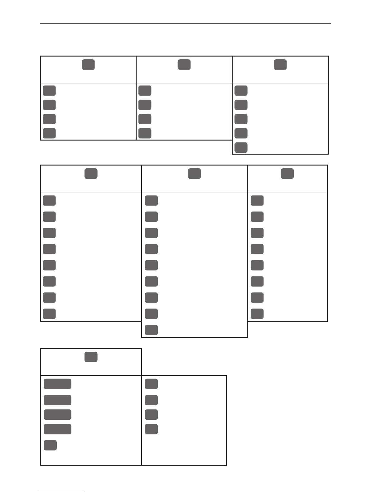
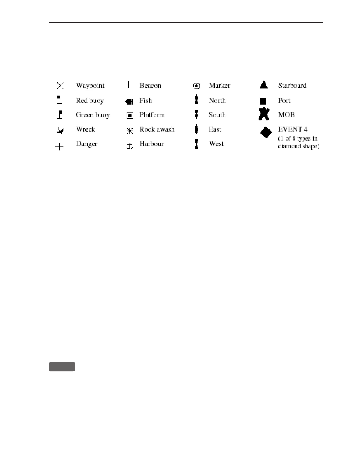
2.5 Choice of symbols
Waypoints and other points appearing on the screen can be marked by one of
18 symbols + 8 event marks in small or large symbols:
2.6 Naming of routes, points etc.
First select the key with the desired letter, then you can either repeat the
keystrokes, which will toggle between e.g. A,B,C,1, or once you have selected
one letter you can go back and forth in the alphabet by means of the +/- keys.
Use the cursor key to go to next space or to go back one space if you make a
mistake.
Depending on the selected language, the 0 (zero) key will hold special characters e.g. Æ Ø Å Ä Ö Ü Ñ, and the 9 (nine) key will hold: . - (empty space)
Press the [CLR] key to delete everything from cursor position and to the right
of cursor in that row.
2.7 Initial start-up
When starting up for the very first time, the first time after loading
a new software or after a master reset: Make sure that all hardware
installation and electrical connections are completed in accordance
to the installation instructions.
PWR
Press and hold the [PWR] key until you have a picture on the screen
The system will perform a software update and when finished, a
new start-up window will be presented on the screen (see example
on next page).
Page 24
Automatic input source setup
Interface has not been set up!
To start automatic input
source setup, make sure that
all connected products are
turned ON, and press ENT.
Start
ENT
∆
∆
Chapter 2-8 CA34/44/54 Fundamentals & initial start-up
After making sure that all connected products are turned ON:
ENT
Press [ENT] to start automatic input source setup, - if a new product
is connected later on, refer to section 9.6 Interface setup.
New window: Automatic input source setup listing Data type, Group
and Source of connected units.
ENT
Press [ENT] to continue
PAGE
Press [PAGE] to scroll through a quick guide which informs of the
use of the keys and where you can enter owner’s setup, etc.
- the quick guide is also accessible via [MENU], [7], [5].
ENT
Press [ENT] when ready to assume normal operation
- go to [MENU], [7], [2] if you wish to make adjustments to the
interface setup.
Heading is only available if a compass was detected at start-up.
PWR
Press [PWR] again to adjust the lighting in the screen and select day
or night display etc., move around in display by means of the cursor
key and change settings with +/- keys, and...
ENT
Confirm with [ENT]
Your present position will automatically be updated within a few minutes. When ready, the ship symbol on the chart will flash, the position
coordinates will stop flashing, and the *** will be replaced by actual
Page 25
CA34/44/54 Fundamentals & initial start-up Chapter 2-9
course and speed figures - see section 6.3 Position display.
Do not start radar transmission before the antenna is warmed up, refer
to section 3.2.3 Start transmission.
Select display language:
MENU
Call up the menu bar, and...
7,1
press [7], [1] to call up the language display
Press up on the cursor to go to the bottom line in the display
+/-
Select language
ENT
Confirm entry
2.8 Turn power on
Starting up for the first time, or after loading a new software, or
after a master reset - see section 2.7. Starting up at any other time:
PWR
To turn on the CAXX, press and hold the [PWR] key until you have a
picture on the screen
ENT
Press [ENT] when the system is ready
2.9 Turn power off
PWR
Call up INFO window, and...
PWR
Press and hold until the curtains begin to close
The CAXX is now turned off. All the data and setups are saved and
stored in the internal memory and, of course, will be available next
time the unit is turned on.
Page 26

Chapter 2-10 CA34/44/54 Fundamentals & initial start-up
Page 27

CA34/44/54 Radar menu Chapter 3-1
3. Radar operation
The CAXX combines chart plotting with radar navigation. For first
time users of Radar, we have included a basic description of the
radar presentation with a basic understanding of how the controls
affect the radar’s operation and display.
The following paragraphs describe the control settings used for
initial display setup, turn-on procedure, inclement weather operation
and finally the turn off procedure. Radar controls are described in
chapter 3.2.
3.1 Radar picture
The radar picture appearing on the display is a map-like representation of the area in which the radar is operating. Typically, the ship’s
position is at the center of the display. The operator may reposition
or offset the ship’s position up to 66% of the radius anywhere on the
screen. The ship’s dead ahead bearing is indicated by the heading
line at the 0° relative bearing.
Coastline contours and landmass are generally depicted in solid
filled yellow, purple, multi-colored (DAY settings) or green (NIGHT
settings) echo areas - choose colors in Pallette setup, section 9.7.
Other surface vessels, and channel buoys, are displayed as smaller
single “blips” or echoes. The radar picture or map can be viewed in
many different ranges from own ship. These sizes are selected by
the range controls. Greater detail of radar echoes nearby own ship is
shown when the short or nearby range scales are selected. The best
technique for assessing the radar presentation characteristics is to
start with using a longer range scale and then switching to shorter
ranges when nearby targets appear, or as the ship approaches the
coastline, harbor, or other vessels in the area.
The long range scales (i.e. 3, 6, 12, 24nm) best show the overview of
the ship’s relationship to landmasses, weather fronts, and large ship
targets at or beyond view.
Page 28

Chapter 3-2 CA34/44/54 Radar menu
3.1.1 Orientation
In the RELATIVE mode, the heading line always appears on the
screen at 0° relative according to the on-screen bearing scale, and is
coincident with the antenna beam passing the ship’s bow. Thus the
top of the displayed picture represents the direction in which the ship
is heading.
All targets appearing on the display are “Relative” to own ship’s
position and heading. As you look outside at targets around you, you
will see that the targets are appearing on the Radar display at the
same relative bearing.
If the vessel alters course to the right, the displayed echoes will
be displaced by an equal amount in bearing in a counterclockwise
direction, and vice versa. These changes in the display pattern with
ship movement is an extremely important characteristic to remember
when maneuvering around nearby vessels, or buoys.
In North Up mode, the heading line will indicate the ship’s heading
in relation to the radar picture, which is presented in north up like a
chart.
The Electronic Bearing Lines (EBL) are available radar tools used
to measure bearings to radar targets from own ship. The bearing
readouts may be in relative or true modes.
3.1.2 Effects of ship’s movement
Radar images can be drawn in two ways on the radar display to
show the ship’s motion. The type of display modes are called “Relative motion” and “True motion”. In Relative motion own ship is
permanently fixed at the center of the display and radar echoes
(targets) move in relation to your vessel. With no movement of the
ship, a steady display of fixed radar echoes is shown. If the ship is
moving ahead on a constant course, echoes appearing at the top of
the display will move downward across the display. Your own ship’s
position will always remain at the center of the display.
The True motion display mode can be compared to your vessel
moving on a map or chart. In True motion mode, the surrounding
landmass echoes remain stationary on the screen and if your ship
is moving at a constant course and speed, you will see your posi-
Page 29

CA34/44/54 Radar menu Chapter 3-3
tion move across the screen towards the edge of the display. Any
other targets which are underway will also be moving on the display
screen at their True course and True speed. All motion seen on the
True motion display is “TRUE” (meaning motion over the ground).
3.1.3 Environmental effects
The effects of weather and water surface conditions generally act to
reduce the ability of radar to detect targets. Weather effects reduce
the long range at which targets can be detected. Water surface clutter (waves) reduces the ability to detect targets close by. Either can
obscure the echoes from targets that may prove dangerous to your
vessel.
You can’t see wind on your radar screen, however you can see its
effects when it produces waves and spray on the water surface. “Sea
Return” is most pronounced in the direction from which the wind is
blowing. Proper use of your Sea clutter control can reduce the effect
of wind and waves, but care must be taken not to increase the control
to the point where weak targets will be overlooked.
Rain, hail and snow can return echoes that appear on your radar
screen as a blurred or cluttered area. Targets within the area of
precipitation can be masked by the clutter. The maximum range of
the radar pulse is greatly reduced as the energy of the radar beam
is scattered and absorbed by the water droplets. Proper use of your
Rain clutter control helps you to look into areas of precipitation to
detect targets.
Buoys are moored to the bottom with concrete via chain. The chain
is longer than the depth of the water to allow the buoys to ride in the
current and go up and down with the tide. Unfortunately this allows
the buoys to lean in the direction of the current. Radar reflectors
built into the buoy do not work well when the side of the buoy is
pointed to the sky. Therefore, the images of the channel markers may
appear faint.
The iron mass and angles of the metal in the structure of a bridge
can cause unpredictable interference patterns on your radar. It is
not unusual for a reflected image to appear on the radar screen in
front of you just as you pass under the bridge. A similar effect is also
common on sailboats where the radar antenna is mounted close to an
aluminum mast.
Page 30

Chapter 3-4 CA34/44/54 Radar menu
Overhead cable crossings can mimic a moving target on your radar
screen. The cable target can appear to be on a collision course. The
entire length of cable does not appear on the screen, only a point
on the cable, and that point keeps changing giving the illusion of a
moving target.
3.1.4 Navigational echoes
Echoes displayed on the radar screen may be large or small, bright
or faint, depending on the size and shape of the object and its angle
relative to your radar antenna. The radar indication is not always the
same as an observer’s visual indication; a nearby small object may
appear to be the same size as a distant large object on the radar. With
experience, however, different targets can be identified by the relative size, brightness, and position of their radar echo returns.
Buoys and small boats are one example of targets that are sometimes
difficult to distinguish from each other. Their movement in the
waves do not present a consistent reflecting surface. Consequently,
their echoes have a tendency to fade and brighten or sometimes
to disappear momentarily. Although buoys and small boats often
resemble each other, usually the motion of one target identifies the
boat from the buoy.
High coastlines and mountainous coastal regions are often observed
at the longest ranges of the radar. However, the first sight of landfill
on the radar’s longest ranges may be a mountain several miles inland
from the coastline and not the actual coastline. The coastline may
not appear on the radar until the vessel has approached land nearer
the line of sight distance.
3.1.5 Racon (Radar Beacon)
A racon is a radar transponder which emits a characteristic signal
when triggered by a ship’s radar. The signal may be emitted on the
same frequency as that of the triggering radar, in which case it is
superimposed on the ship’s radar screen automatically.
The racon signal appears on the screen as a radial line originating
at a point just beyond the position of the radar beacon or as a Morse
code signal displayed radially from just beyond the beacon.
Page 31

CA34/44/54 Radar menu Chapter 3-5
3.1.6 Sea return
Not all radar echoes are produced by hard navigation items such
as boats, buoys and land. Some radar echoes may be received from
irregularities on the surface of the water, particularly at close range by
breaking wavecrests, particularly in windy weather and in heavy seas.
These echoes appear on the radar screen on the short range scales
as multiple small echoes next to own ship. Under high winds and
extreme conditions the echoes from sea clutter may appear as dense
background of clutter forming the shape of an almost solid disc,
as far as one to three miles in all directions from own ship, but the
worst direction is where the wind is blowing towards the ship. The
radar has a sea clutter control, which can be used to minimize the
effects of sea clutter pickup on the screen.
3.1.7 Storm and rain squall returns
The radar can also see echoes from rain or snow. Echoes from rain
squalls consist of countless small echoes, continuously changing in
size, intensity, and position. These returns sometimes appear as large
hazy areas on the display depending on the intensity of the rainfall
or snow in the storm cell. The cells usually may be visible at long
distances due to their high altitude above the radar horizon and are
very helpful for observing potential bad weather conditions. If the
returns from rain squalls are not desired, the Rain clutter control can
be adjusted to minimize the effect on the radar screen.
3.1.8 Blind sectors or shadow effect
Funnels, masts or derricks, (when located near the antenna array)
may cause shadows. Shadow areas can be recognized since beyond
the obstruction there will be a reduction of targets and noise intensity, although not necessarily a complete cutoff seen on the screen.
However, if the shadow angle is more than a few degrees, there will
be a blind sector.
In some shadow sectors the beam intensity may not be sufficient to
obtain an echo from a very small object even at close range, despite
the fact that a large vessel can be detected at a much greater range.
For this reason, the angular width and relative bearing of any shadow
sector should be determined at installation. Sometimes shadowing
can be seen on the screen by increasing the radar gain until noise is
Page 32

Chapter 3-6 CA34/44/54 Radar menu
present. Darker sectors indicate possible shadowed areas. This information should be posted near the display unit, and operators must be
alert for objects in these blind sectors.
3.1.9 Side lobes
Echoes on the radar screen are not always the direct returns to the
radar antenna. There are many types of false echoes that can appear
on the display if certain conditions occur. The sections that follow,
briefly describe the echo patterns that may be produced by these
false echoes and their likely cause. It should be noted that the radar
operator, through observation, practice, and experience usually can
detect these conditions very quickly.
A very small part of the RF (Radio Frequency) energy from each
transmitted pulse is radiated outside the radar’s narrow beam, producing side lobe patterns. Side lobes normally have no effect from
distant or small surface objects, but the echo from a large object at
short range may produce an arc pattern on the radar screen similar
to a range ring, or appear as a series of echoes forming a broken arc.
Side lobe echoes normally occur at a range below 3 miles and usually can be reduced through careful reduction of the Gain or proper
adjustment of the Sea clutter control.
3.1.10 Radar interference
Whenever two or more radar equipped vessels are operating within
reception range of each other, mutual interference is likely when the
radars are operating near the same frequencies. This interference
usually appears on the screen as a series of small dots. The interference seems to move from the PPI center (center of radar screen),
sometimes in a straight line, but more often in a long, sweeping
curve. This type of interference is more noticeable on longer range
scales. This does not, as a rule, impair the effectiveness of the radar
as a navigational aid. Since the interference can be completely eliminated by turning IR “ON” in the function menu. The IR feature is
normally left “on”.
Page 33

CA34/44/54 Radar menu Chapter 3-7
3.1.11 False echoes
Occasionally, echoes may appear on the screen at positions where
there is no actual target. This type of target is called a False Echo.
Sometimes they are known as Ghost Images, Indirect Echoes or
Multiple Echoes depending on how they are generated.
Ghost images usually have the appearance of true echoes, but, in
general, they are intermittent and poorly defined. A true ghost image
retains a fixed relationship with respect to the true image and characteristically produces a more arc-like appearance with a tendency
to smear on the screen. Ghost images are sometimes caused by large
targets which have a wide, smooth surface as they pass by near your
own ship.
Ghost images sometimes are referred to as indirect echoes. Indirect
echoes may appear when there is a large target, such as a passing
ship at a short range, or a reflecting surface, such as a funnel or
spotlight on your own ship in line with the antenna. The signal, on
first striking the smooth side of the large target, will be reflected,
and these subsequent echo returns to the antenna are shown on the
display. However, the same reflection may also hit other masts or
obstacles and then be picked up by the radar antenna with enough
strength to appear as a target on the radar screen at various locations.
Multiple echoes could appear if there is a large target having a wide
vertical surface to your own ship at a comparatively short range. The
transmitted signal will be reflected back and forth between the wide
vertical surface of the target and your own ship.
Thus, multiple echoes will appear beyond the true target’s echo on
the same bearing as shown below.
True e cho
Multiple
echoes
Page 34

Chapter 3-8 CA34/44/54 Radar menu
3.2 Radar menu
The Golden Rule! Today’s radars are packed full of neat features
designed to make your cruising more enjoyable and safer. Use these
features when you can, but remember the old axiom KISS (keep it
simple sailor). If a target shows on the display, there most likely is
something there. If there are no targets shown on your display, it
doesn’t guarantee there are no other objects around. Maintain a good
visual watch, proceed at a safe speed and enjoy your boating.
1
RADAR
The displays obtained from this
menu can easily be accessed from
the main function key [RADAR]
- see section 3.2.1.
To access RadarChart overlay
- see section 3.2.6.
1
Radar
2
Dual Radar
3
Radar & Chart
4
Custom screen
The Radar display will be presented in full screen with the radar
control menu placed in the right side of the display. Press [ADJ] to
access the control menu, where the most common adjustments are
made - see section 3.2.5.
The Dual Radar display requires a full-screen presentation, with the
standard display in the left half of the screen and the secondary radar
display in the right half of the screen. The two half-screen radar displays can be set up and operated independently - see section 3.2.8.
The Radar & Chart display requires a full screen presentation, with
the radar display in the left half of the screen and the chart display in
the right half of the screen - see section 3.2.9.
The Custom screen will present multiple window combinations
(section 3.2.1), where the radar display will be fixed in the left half
window and the two quarter windows i.e. (default) a chart display
and an echo display can be exchanged with different displays.
To access one of the displays via the menu e.g.:
MENU
Call up the menu bar, and...
1,1
press [1] and [1] to call up the Radar display in full screen
Page 35

CA34/44/54 Radar menu Chapter 3-9
3.2.1 Shortcut to the pages in the radar-series
The RADAR function is one of the main functions in the CAXX.
Each page under the [RADAR] key will include a window representing the radar function. It is not possible to exchange main function
displays with a new display. Refer to section 2.1, 2.1.1 and 2.1.2 for
further information on the display and page system.
From any display:
RADAR
Long press on the [RADAR] key will toggle between:
Radar full screen Dual Radar Radar & Chart Custom screen
All the displays are fixed, except for the two quarter windows in the custom
screen, which can be exchanged with a different display selected via the menu.
From radar display:
RADAR
Short press on the [RADAR] key will toggle overlay on/off
- see section 3.2.6.
Radar display RadarChart overlay
3.2.2 Initial radar display setup
After the installation is completed, check the Radar setup (section
9.1) if the Antenna height is correct and the Heading adjust is
zero degrees to ship’s center line. If not, carry out adjustments as
described in the Radar setup. The Scanner type is preset to Auto
detect and as such, the system will automatically initiate the correct
parameters for the connected scanner.
Page 36

Chapter 3-10 CA34/44/54 Radar menu
3.2.3 Start transmission
Normally, when starting the transmission, it will take approx. two
minutes for the antenna to warm up and be ready for transmission.
For initial start-up and after long storage, see below.
Make sure nobody is standing close to the radar antenna when it
starts to rotate after the transmission is activated!
RADAR
Shortcut to radar display
ENT
Call up the Radar quick menu
RADAR
Turn ‘Power on’
The legend ‘Detecting’ will appear on the screen while the system is
checking which scanner is connected. When the scanner is detected,
a countdown to zero will appear on the screen which will allow two
minutes for the scanner to warm up before it enters Standby mode
and is ready for use.
When ready to start transmission:
ENT
Call up the Radar quick menu
GOTO
Start transmission
Starting up the first time after installation or after long storage (6
months), the antenna will need an extra 20 minutes to warm up,
so after Power on and going into Standby, the radar must be left in
Standby mode for the extra 20 minutes it will take to warm up the
antenna properly. This way you will contribute to the lifetime of the
magnetron in the radar antenna.
3.2.4 Shut down procedure for the radar function, or back to ‘Standby’
To disengage the radar transmission temporarily, you can return the
radar function to Standby mode:
ENT
Call up the Radar quick menu
GOTO
Enter Standby mode
Page 37

CA34/44/54 Radar menu Chapter 3-11
To resume the radar transmission:
ENT
Call up the Radar quick menu
GOTO
Start transmission
To shut down the radar function:
ENT
Call up the Radar quick menu
RADAR
Turn ‘Power off’
3.2.5 Standard radar display
The standard radar display will require full screen presentation.
RADAR
Shortcut to radar display
Or load the radar display via the menu:
MENU
Call up the menu bar, and...
1,1
load the Radar display
The top line in the radar display indicates the course and speed
of the ship together with the position of the ship, which will be
exchanged with the position of the cursor when activated on the
radar display (heading input is required). The control menu will
appear in the right side of the radar display in full screen.
‚Press ENT to operate‘ - refer to section 3.2.6 Radar quick menu.
Page 38

Chapter 3-12 CA34/44/54 Radar menu
Use cursor to activate and move the cross cursor on the radar back-
ground - press [CLR] to remove cursor.
EBL
Activate EBL-VRM1, and use cursor to move EBL-VRM1 around
in the radar background - more details further ahead in this section
- press [EBL] again, or [CLR] to remove EBL-VRM1.
ADJ
Open for adjustment
Use cursor to move around in the control panel
+/-
Toggle between available values
0-9
Key in new values
ENT
Confirm changes by pressing [ENT] (or [MENU])
There is no regret or “exit without making any change”-key from the
control panel. As soon as the keys are pressed to change a function,
the actual change is immediately carried out.
Orientation can be set to:
HU RM (Head-Up in Relative Motion): The heading line always
appears on the display at 0 degrees as the antenna beam passes the
bow of the vessel. Targets appearing on the display are relative to
your own ship. Head-up mode gives an easy interpretation of the
situation around your boat.
NU (North-Up): In this mode, targets are displayed at their measured
distances and direction relative to north. North being at the top of
the display. To operate in NU mode will require valid heading from
connected compass.
CU (Course Up): The heading line appears to point upwards within
the range of the rotation resolution (default is 15°). If the vessel turns
more than e.g. 15°, the radar picture will also turn to make the heading line continue pointing upwards.
TM (True Motion): Own ship moves past land, buoys and fixed
objects. To operate in TM mode will require valid GPS position and
compass heading.
Page 39

CA34/44/54 Radar menu Chapter 3-13
RM (Relative Motion): The ship will stay in the center of the screen
or at an offset position and targets will appear relative to own ship’s
position.
If receiving the alarm: “Heading missing” or “Position mising” the
system will change to Head-Up in Relative Motion after 60 seconds
and at the same time inform of “Changing to HeadUp” in a pop-up
window.
0.50nm
indicates the displayed range in the radar picture.
Power off indicates that the radar function is not active.
TI is the Tuning Indicator, which provides an indication of the
receiver tuning.
Tun e – make manual adjustments to Tune by means of the +/- keys,
and return to AUTO mode by pressing [CLR].
Tune cont rol
– is a variable control used to tune the receiver in the
radar antenna for maximum target returns on the display. If no land
or ship targets are available, the operator may tune for maximum sea
clutter. The tuning indicator will show the strength of tuning peak
conditions and is tuned for maximum deflection. Tuning of the radar
should be performed on a 3nm range scale or higher.
Gain – Auto mode
can be used in most situations, but in some situations manual adjustment leads to better performance of the system.
Make manual adjustments to Gain by means of the +/- keys, and
return to AUTO mode by pressing [CLR].
Gain control
adjusts the gain level of the radar’s receiver. The Gain
control level is usually set for the best target presentation with a slight
noise speckle in the background on the 12 or 24nm range. A semiautomatic Gain reduction is used on shorter ranges to improve target
definition. Use some caution when adjusting the Gain control. If gain
is set too low, small or weak targets may be missed. If the gain is set
too high on short ranges, the display may become excessively covered
with noise speckle making target observation difficult.
Sea –
Auto mode is optimized for open sea and is recommended when
the distance to shore is over 300 meters. Closer to shore and when
approaching a harbor, choose Harbor mode
.
Make manual adjustments to Sea by means of the +/- keys, and
Page 40

Chapter 3-14 CA34/44/54 Radar menu
return to AUTO mode by pressing [CLR].
Press [CLR] to toggle between HBR (Harbor) and AUTO mode.
Sea control
– is used on the shorter ranges to suppress the effects
of sea clutter close to own ship by reducing the nearby gain level.
It can effectively reduce the strength of the mass of random echoes
received from nearby sea clutter for up to approx. 1 to 2 nm depending on wave and sea conditions. Sea control is set to reduce the
strength of these echoes such that the clutter appears only as intermittent small dots, yet stable targets can still be distinguished.
If manual adjustments are made, the setting will affect the system’s
ability to detect targets and remove sea clutter in heavy sea situations.
Rain – the rain clutter filter enhances the leading edge of a target
whereas the signal behind the leading edge area of rain will be
depressed. This can also be of great advantage on shorter ranges
to distinguish between two very close echoes on the same bearing
which may otherwise merge and appear as one echo.
To properly adjust for rain clutter:
1. Set rain clutter to zero.
2. Slowly increase rain clutter until the hazy area caused by the rain
or snow become less dense. Increasing it too much will not only
remove the rain clutter, but also other weak targets.
Note! Since Rain and Snow are continually changing in size and
density, tweaking of the rain clutter adjustment is necessary to
maintain the best results. Manual fine tuning of Gain and Sea may
improve the performance.
EBL (Electronic Bearing Line) - bearing and distance (read-only)
from ship’s position to cursor. Two independent EBLs are available
- see section 3.2.6.
VRM (Variable Range Marker) - bearing and distance (read-only)
from ship’s position to VRM cursor. Two independent VRMs are
available - see section 3.2.6.
Cursor - bearing and distance (read-only) from ship’s position to
cursor.
Trails after targets – toggle between OFF, 30sec, 1min, 2min,
5min, 10min, 15min, 30min, PERM (permanent).
Using the Trails feature will show the trails of target movement as an
Page 41

CA34/44/54 Radar menu Chapter 3-15
after-glow or wake behind the moving targets or own ship.
If the range scale is changed, the trails are cleared and new trails will
be drawn on the screen. The trails are drawn for anything that moves
on the screen, including sea gulls, sea clutter, buoys, and shoreline.
Own trail – toggle between OFF and ON. This function will require
that ‘Trails’ (above) is activated and mode of orientation is TM.
RR = RangeRings – toggle between # *.** (as display example), *.**
(no RR figures), OFF (no RR)
GZ (Guard Zone alarm)
– The use of the Guard zone feature built
into the radar can detect approaching vessels entering your guard
zone. You can use the guard zone while you are moving or when
anchored to protect you in a full 360 degrees. The audio alarm can be
sounded from the unit or through an external speaker/buzzer wired
into the system – see Electrical connections in Installation manual.
In Head Up mode the GZ relates to the vessel and in North Up or
Course Up it relates to geographic north.
Define the guard zone by means of the EBL and VRM markers:
1. Press the [EBL] key and move cursor (EBL-VRM1) to make the
left side and top of the guard zone.
2. Press [ENT], [2] and move cursor (EBL-VRM2) to make the right
side and bottom of the guard zone. The guard zone will be gener ated clockwise from EBL1 to EBL2.
3. Press [ADJ] and move cursor to the GZ line. Use the [+] key to
toggle between: IN / OUT / OFF.
IN = the alarm will be activated if any target enters the defined
guard zone.
OUT = the alarm will be activated when all targets have left the
defined guard zone i.e. at least one target must be present inside
the GZ when the function is activated.
4. Press [ENT] to exit the control panel.
5. Press and hold [CLR] to clear the EBL-VRMs. This will give a
better view of the defined guard zone.
Page 42

Chapter 3-16 CA34/44/54 Radar menu
The guard zone is not available in the secondary radar display in
Dual Radar mode.
IR (Interference Rejection) – will reduce false echoes from other
radars nearby, see section 3.1.10.
Stretch – toggle between AUTO, ON, OFF.
AUTO (default) - small targets are enhanced at ranges above 12 nm.
ON - all targets will be enhanced.
OFF - all targets will remain unchanged.
Rpm – will determine the scanner rotation (full screen presentation).
Manually, the rotation speed can be set to either 24 or *48 rpm,
depending on the scanner type (use +/- keys).
*Running 48 rpm (double update rate) is liable to reduce the lifetime
of the mechanical parts.
HDG
– your heading will be shown (full screen presentation) in
degrees from connected compass. If no compass is connected, you can
use the course (COG) from the built-in GPS module by changing “Use
COG as internal heading” from NO to YES in the interface setup.
Press [MENU], [7], [2], and then press [PLOT] repeatedly until the
tab reads Compass.
When using the GPS course as replacement for heading input, the
accuracy will be reduced in relation to speed, wind and current.
Pulse - can be set to SHORT, NORMAL or LONG.
NORMAL (default) will not change the presentation of targets.
SHORT - (press the [-] key to access) will enhance target resolution at range 0.5-6.0 nm. However, this setting may result in making
some smaller targets disappear.
LONG - (press the [+] key to access) will enlarge targets on screen
and improve target detection. However, this setting will also enlarge
any noise picked up.
Depth - readout in meters, feet or fathoms from built-in echosounder
function or external depth source.
Page 43

CA34/44/54 Radar menu Chapter 3-17
3.2.6 Radar quick menu
From active radar display:
ENT
Call up the Radar quick menu
Radar quick menu
RADAR
Power On
GOTO
Transmit
1
Activate EBL-VRM1
2
Activate EBL-VRM2
3
Activate Cursor
4
Show Navigation Point
5
Heading Line
6
Clear Trails
CHART
Show Overlay Chart
PLOT
Show Overlay User Data
ADJ
Overlay Chart Setup
MENU
Exit
If working with both EBL-VRM cursors, you can toggle between
which one should be active via the quick menu.
RADAR
Power On/Off - Turning power on will activate scanner warm up
and enter standby mode, see section 3.2.3.
GOTO
Transmit/ Standby - Transmit will start transmission and antenna
rotation, see section 3.2.3.
1
Activate EBL-VRM1
A dotted line + circle will be drawn on the screen. Use the cursor key
to move the EBL-VRM1 cursor. By placing the square cursor point
over a target or over an object, it will indicate the distance to same.
To turn off: Press [ENT], [1] again to hide EBL-VRM1.
Long press on [CLR] will turn off all active cursors.
Toggle on/off directly from the [EBL] key.
Page 44

Chapter 3-18 CA34/44/54 Radar menu
2
Activate EBL-VRM2
A dotted line + circle will be drawn on the screen. Use the cursor key
to move the EBL-VRM2 cursor. By placing the square cursor point
over a target or over an object, it will indicate the distance to same.
To turn off: Press [ENT], [2] again to hide EBL-VRM2.
Long press on [CLR] will turn off all active cursors.
3
Activate Cursor - will activate cursor on radar display. Press again
to turn off cursor, or press [CLR]. Long press on [CLR] will turn off
all active cursors on the radar display.
4
Show/Hide Navigation Point
- this function will require a valid
position, and heading input from connected sensor. When a navigation
mode is active, the approaching waypoint can be shown on the radar
display. Turning the navigation mode off will temporarily disable
the function, because there is nothing to show - but when navigation
is started up again, the function will also become active again. You
will not have to turn it on and off all the time. Press [ENT], [4] Hide
Navigation Point if you no longer want the waypoint to be shown on
the radar display.
5
Heading Line - by pressing the [5] key the heading line will disap-
pear for approx. 5 seconds.
6
Clear Trails - will clear all trails, both from targets and own boat.
CHART
Show/Hide Overlay Chart - dedicated chart overlay on the radar
display.
This function will require a valid position, and heading input
from connected sensor.
The type of chart data/objects shown on the
screen can be adjusted in the ‘Overlay chart setup’, see section 3.2.7.
PLOT
Show/Hide Overlay User Data - plotted user data overlay on the
radar display.
This function will require a valid position, and head-
ing input from connected sensor.
The type of user data shown on the
screen can be adjusted in the ‘User data’ group in the ‘Overlay chart
setup’, see section 3.2.7.
ADJ
Overlay Chart Setup - will open for change to the current setup.
The changes will only affect the chart used with the overlay - see
section 3.2.7, and section 4.5.2 Description of chart features.
MENU
Exit Radar quick menu
Page 45

CA34/44/54 Radar menu Chapter 3-19
3.2.7 RadarChart overlay
Radar and chart images merged into one presentation takes away the
guesswork of interpreting radar information by providing the full
picture. The overlay is a feature under the radar function, which consists of three layers of information. The first layer is the chart with
the ship’s symbol indicating precisely where you are at all times. The
second layer is the radar image with targets. And finally the third
layer adds the coast lines, buoys, lights, user data and other vital
navigational data which always will be shown on top of the radar
targets. Radar operation will be as usual with full access to the radar
control menu. The dedicated chart used with the overlay is adjustable
via the Radar quick menu.
The overlay function will require the following conditions: Valid
position, valid heading information, and Radar orientation mode
must be in NU (North Up) or CU (Course Up). The overlay is disabled in HU (Head Up).
The overlay function can not be activated in the ‘Radar & Chart’
display.
From active radar display:
RADAR
Short press will toggle the overlay on/off
Calling up the overlay function via the [RADAR] key will automatically show the dedicated chart together with any user data plottet in
the area presented on the screen.
The amount of information in the overlay is controlled via the Radar
quick menu where you can Hide/Show Overlay Chart or Hide/Show
Overlay User Data, or enter Overlay Chart Setup to turn off some of
the objects if the screen is too cluttered with information.
ENT
Call up the Radar quick menu
CHART
Hide/Show Overlay Chart
- special chart dedicated to the overlay.
PLOT
Hide/Show Overlay User Data
- plottet waypoints, routes, etc. stored in the memory.
If you choose to e.g. Hide Overlay User Data, then the Overlay
Chart will be shown on the radar display and a short press on the
[RADAR] key will toggle the overlay on/off, but now only with the
Chart data, as the User Data is currently ‘hidden’.
Page 46

◄
GOTO
Presentation Dep
PLOT
►
Display mode OVERLAY
Orientation NORTH UP
Rotation resolution 15°
Motion RELATIVE
Extended level range OFF
MENU
Exit Accept
ENT
∆
∆
General
Chapter 3-20 CA34/44/54 Radar menu
Color presets for the overlay display
Different color combinations of radar targets and chart or radar
background color are available:
PWR
Call up the Light and power pop-up window
1 - 9
Select a different number in the color Palette
ENT
Confirm the change
The color palettes from 1 to 4 are fixed, palette 9 is preset with multi
color radar targets, the rest (5-8) can be customized to suit individual
needs. See how in section 9.7.
Adjustment of overlay settings
The special chart used with the overlay is not used anywhere else in
the system and therefore has its own individual setup. A description of
the chart features can be found in section 4.5.2. To access the overlay
chart setup, the active window must contain a radar display, and then:
ENT
Call the Radar quick menu
ADJ
Open for change in the overlay chart setup
Page 47

CA34/44/54 Radar menu Chapter 3-21
The tabs indicate which groups are available in each display mode e.g.
in the above example,
OVERLAY display mode, you have access to the
groups in black: General, Areas and User data. The two groups in red
i.e. Presentation and Depth are only adjustable in
CUSTOM display
mode. See further on in this chapter for more details.
+/-
Select display mode: OVERLAY, FULL, CUSTOM, SIMPLE,
FISHING, LOW
PLOT
Go to the next group
GOTO
Step back to the previous group
Scroll up/down in the chart settings
- functions in light grey are not accessible in selected display mode.
+/-
Toggle between available settings
ENT
Confirm changes, or...
MENU
Abandon Chart setup without making any changes
Display modes in the overlay chart setup
There are 6 different display modes to choose from: OVERLAY (default),
FULL, CUSTOM, SIMPLE, FISHING and LOW. When a group is shown in
red or a function is shown in light grey it is not available in the selected display mode. The default settings in the various display modes are:
Group: General - specification of chart display in general.
The available functions are according to display example on previous page for
all display modes and any change of the default settings will be applied in all
display modes.
Group: Presentation - specifies presentation of marine, land and chart topics
The default settings in this group are fixed in all display modes, except for
*Custom where it is possible by the user to turn a feature ON (shown on the
chart) or OFF (not shown on the chart), etc. - see next page.
Page 48

Chapter 3-22 CA34/44/54 Radar menu
C-MAP features
Overlay Full *Custom Simple Fishing Low
Marine:
Names
Nav-Aids
Light Sectors
Attention Areas
Tides, currents
Nature of seabed
Ports
Tracks, routes
Buoys
Signals
Land:
Natural features rivers
Natural features
Cultural features
Landmarks
Chart:
Grid
Boundary lines
Mixing levels
Declutter
OFF
INT
OFF
ON
ON
ON
OFF
ON
ON
ON
OFF
OFF
OFF
OFF
AUTO
OFF
ON
ON
ON
INT
ON
ON
ON
ON
ON
ON
ON
ON
ON
ON
ON
ON
AUTO
AUTO
ON
ON
OFF
INT
OFF
ON
ON
ON
OFF
ON
ON
ON
OFF
OFF
OFF
OFF
AUTO
OFF
ON
ON
ON
INT
OFF
ON
ON
OFF
ON
OFF
ON
ON
ON
OFF
OFF
ON
AUTO
AUTO
OFF
ON
ON
INT
OFF
ON
OFF
ON
OFF
OFF
ON
ON
OFF
OFF
OFF
OFF
AUTO
OFF
ON
ON
OFF
INT
OFF
OFF
OFF
OFF
OFF
OFF
OFF
OFF
OFF
OFF
OFF
OFF
AUTO
OFF
OFF
ON
Group: Depth - specifies the presentation of depth lines, levels, etc. on chart
The default settings in this group are fixed in all display modes, except for
*Custom where it is possible by the user to alter the features. The color indication for depth levels 1, 2 and 3 is determined by the color palette in the SETUP
menu.
C-MAP features
Overlay Full *Custom Simple Fishing Low
Soundings
Underwater objects
Depth Lines
Depth Lines>
Depth Lines<
Depth Areas
Depth
Level 1
Level 2
Level 3
OFF
OFF
ON
0000m
9999m
ON
0-002m
2-009m
9-MAX
ON
ON
ON
0000m
9999m
ON
0-002m
2-009m
9-MAX
OFF
OFF
ON
0000m
9999m
ON
0-002m
2-009m
9-MAX
ON
ON
ON
0000m
5m
ON
0-002m
2-009m
9-MAX
ON
ON
ON
0000m
9999m
ON
0-002m
2-009m
9-MAX
OFF
ON
OFF
0000m
5m
OFF
0-002m
2-009m
9-MAX
Page 49

CA34/44/54 Radar menu Chapter 3-23
Group: Areas - specifies the presentation of different areas on chart
The default settings in this group are the same for all display modes and any
change of the default settings will be applied in all display modes.
The features can be changed from FILLED to CONTOUR:
C-MAP features
All display modes
Land areas
Depth areas
Caution areas
Dredged areas
FILLED
FILLED
FILLED
FILLED
Group: User data - user defined objects can be visible or invisible on chart.
The default settings in this group are the same for all display modes and any
change of the default settings will be applied in all display modes.
Chart features Defaults and choice of settings
Waypoints
Non active waypoints ON
Waypoint names ON
Waypoint depths ON
Routes
Non active routes AS SELECTED
Route names ON
Tracks
Non active tracks AS SELECTED
Track names ON
Lines
Lines AS SELECTED
Line names ON
Targets
Targets AS SELECTED
Target names ON
All the features in the user data level
that are set as default to ON= shown
on chart, can be changed to OFF= not
shown on chart.
Non active routes and tracks, all lines
and all targets are default to:
AS SELECTED= the choices made
for a particular route etc via the menu
e.g. MENU, 6, 2, ENT, ENT - Edit
route, where ‘Course line’ can be set
ON or OFF.
‘AS SELECTED’ can also be changed
to ‘ALL ON’= shown on the chart,
or ‘ALL OFF’= not shown on the
chart.
Page 50

Chapter 3-24 CA34/44/54 Radar menu
3.2.8 Dual radar display
MENU
Call up the menu bar, and...
1,2
load the Dual Radar display
Standard radar display Secondary radar display
This feature requires a full-screen presentation, with the standard
display in the left half of the screen and the secondary radar display
in the right half of the screen. The two half-screen radar displays can
be set up and operated independently.
To make adjustments in the standard radar display (left half screen),
the window must be active:
WIN
Toggle between active windows on screen
ADJ
Open for adjustment
- by pressing [ADJ] again will toggle between 1st and 2nd half of
control menu.
Use the cursor to move around in the control menu
- and toggle between available values with the +/- keys, and insert
data by the numeric keys.
ENT
Confirm changes by pressing [ENT] or [MENU]
To make adjustments in the secondary radar display:
WIN
Make the secondary radar display active
Page 51

CA34/44/54 Radar menu Chapter 3-25
Carry out adjustments by using the same procedures as described in
section 3.2.5 for the standard radar display, except for the guard zone
which is not available in the secondary radar display.
Indication of HDG (heading), Rpm (scanner rotation speed) and
Pulse is only available in full screen presentation.
3.2.9 Radar & Chart display
MENU
Call up the menu bar, and...
1,3
load the Radar & Chart display
The RadarChart overlay is not available in this display!
WIN
Toggle between active windows on screen
• Synchronize cursors or scale and range (will require a valid posi-
tion, and heading input from connected sensor)
In synchronized mode the orientation mode of the chart is set to the
same as the radar orientation. When position data is available the
chart scale is adjusted to approximately the same range as the radar.
When heading data is available and a cursor is active, the chart
cursor will be set to the radar cursor position.
The lock function is controlled by the radar display, which means
that e.g. moving the cursor in the radar display will move the cursor
in the chart display as well. However, when moving the cursor in the
Page 52

Chapter 3-26 CA34/44/54 Radar menu
chart display, nothing will happen in the radar display, because the
synchronization is ‘one way only’.
The lock function is automatically activated when the required data
is available. When the data is not available, the radar display and the
chart display will both function as individual standard displays. This
synchronized feature is only available in the Radar & Chart display.
3.2.10 General features for the radar operation
• Alarms:
The alarms that can appear in connection with the radar operation,
are:
- Bearing pulse alarm (check if scanner is rotating)
- Bearing zero alarm (check if scanner is rotating)
- Changing to Head-Up alarm (indicates the orientation mode has
changed - see section 3.2.5 and 3.2.7)
- Communication failure alarm (check connection to scanner)
- Communication time-out failure alarm (no communication
between display and scanner)
- Guard Zone alarm (see GZ under section 3.2.5)
- Heading missing alarm (check connection to compass)
- Position missing alarm (see Position update under section 6.3)
- Rotation lock alarm (check if scanner is rotating)
- Trigger fail alarm (check connection to scanner)
• Off-center mode (only when operating in RM - Relative Motion)
– permits the operator to obtain a greater view in the direction of
interest. Place the cursor within 2/3 of the display and press the [0]
key. The ship’s position will now be moved to the cursor position and
thereby increasing the desired area of view. To deactivate the Offcenter mode, press [CLR] and [0]. This will replace the ship’s position back at the center of the display. If the radar system is turned off
while the Off-center mode is on, at next power up the offset mode
will still be on.
• PLOT function – will require that a heading sensor (Gyro or Compass) is connected to the CAXX. If so, then you can plot the actual
cursor position on the radar display by pressing [PLOT], [2] from the
radar display, and thereby save the position in the WP-list as a
waypoint i.e. you can give the plotted waypoint a new name/number,
symbol, color, etc.
Page 53

CA34/44/54 Radar menu Chapter 3-27
• Radar colors - There are several color settings to choose from for
the radar display. See Palette setup ([MENU],[7],[3]).
• Range - The extension of the range depends on how powerful the
connected radar antenna is. There are several ways of adjusting the
range on the screen, the quickest way is:
1-9
Use one of the shortcut keys to quickly go to a different range:
Press [1] = 0.125 nm [2] = 0.25 nm [3] = 0.50 nm
[4] = 0.75 nm [5] = 1.5 nm [6] = 3 nm
[7] = 6 nm [8] = 12 nm [9] = 24 nm
+/-
Or you may use the +/- zoom keys to go to a different range
ADJ
Or from the active control panel: use the cursor key to highlight the
current range scale, then adjust the range scale with approx. 10 percent each time you press the +/- keys.
• Show navigation waypoint on radar display - (will require a
valid position, and heading input from connected sensor)
When a navigation mode is active, the approaching waypoint can be
shown on the radar display
:
ENT
Call up Radar quick menu
4
Show navigation waypoint
Turning the navigation mode off will temporarily disable the function,
because there is nothing to show - but when navigation is started up
again, the function will also become active again. You will not have to
turn it on and off all the time. Press [ENT], [4] Hide navigation waypoint if you no longer wish to have it shown on the radar display.
• Targets - The shape of the target has a direct affect on the image
displayed. A flat surface at right angles reflects a good image. Flat
surfaces at shallow angles reflect very poor images. A concave
surface will concentrate the reflective energy and display an image
larger than normal. Convex surfaces will scatter the energy and display week images. A conical surface may not display any image.
The texture of the target surface also controls the amount of reflected
signal, and therefore the image displayed. A smooth surface is a good
reflector, while rough surfaces tend to break up the reflection.
Page 54

Chapter 3-28 CA34/44/54 Radar menu
Composition - materials such as metal and water are good reflectors. Others, such as wood and fiberglass are poor reflectors.
3.3 Demo mode
For the purpose of a demonstration, the radar function has a demo
mode, which can present a simulated radar picture without having a
radar scanner connected.
Warning! Any adjustments/setups already made to the radar func-
tion will return to default settings when selecting the Demo mode.
To activate the demo mode:
MENU
Call up the menu bar, and...
7
Open the SETUP menu
RADAR
Load the Radar setup
- a warning will pop up that you are about to change settings for the
radar, press [MENU] to abandon, or [ENT] to continue.
Use the cursor to go to ‘Scanner type’, and select ‘Demo’ with the
+/- keys
ENT
Accept change & exit Radar setup
ENT
Call up Radar quick menu
RADAR
Turn ‘Power on’
- the legend ‘Detecting’ will appear on the screen for a short while,
then a countdown of 20 seconds will start before the system enters
Standby mode. It now says ‘Standby’ on the screen.
ENT
Call up Radar quick menu
GOTO
Start transmission
+/-
Use the +/- keys to adjust the range and presentation
The legend Demo will stay in the top left of the screen to indicate
the demo mode is active.
Page 55

CA34/44/54 Radar menu Chapter 3-29
Bring the Demo mode in Standby:
ENT
Call up Radar quick menu
GOTO
Go to Standby mode
- this way you can easily return to the simulated radar picture by
repeating the [ENT] and [GOTO] sequence.
Turn off the Demo mode and return to normal operation:
ENT
Call up Radar quick menu
RADAR
Turn ‘Power of f ’
MENU
Call up the menu bar, and...
7
Open the SETUP menu
RADAR
Load the Radar setup
- a warning will pop up that you are about to change settings for the
radar, press [MENU] to abandon, or [ENT] to continue.
Use the cursor to go to ‘Scanner type’, and select ‘Auto detect’ with
the +/- keys
ENT
Confirm changes & exit Radar setup
Page 56

Chapter 3-30 CA34/44/54 Radar menu
Page 57

CA34/44/54 Chart menu and INFO windows Chapter 4-1
4. Chart menu
2
CHART
The displays obtained from this menu
can easily be accessed from the main
function key [CHART] see section 4.1.
RadarChart overlay is accessed via the
radar display - see section 3.2.7.
1
Chart
2
Dual Chart
3
Custom screen 1
4
Custom screen 2
For safety reasons, navigation with electronic charts should always
be combined with authorized paper charts.
The chart display opens for the built-in world chart, as well as the
optional, detailed C-MAP electronic chart system, which of course
will require that a C-MAP NT+ C-card is inserted in one of the
drawers below the keypad. The chart appearing in full screen with
smaller range as default, is the only chart which can be inserted into
a different display via the menu.
The Dual Chart display will provide a chart in two different scales,
one for detail (smaller range) and one for overview (greater range).
The two custom screens will present multiple window combinations (section 4.1), where the chart with greater range as default will
be fixed in a quarter window. The chart with smaller range will be
fixed in the left half window in both custom screens. Adjustments
can be made individually to each chart (section 4.5).
To access one of the displays via the menu e.g.:
MENU
Call up the menu bar, and...
2,1
press [2] and [1] to call up a Chart in full screen
4.1 Shortcut to the pages in the chart-series
The CHART function is one of the main functions in the CAXX.
Each page under the [CHART] key will include a window representing the chart function. It is not possible to exchange main function
displays with a new display. Refer to section 2.1, 2.1.1 and 2.1.2 for
further information on the display and page system.
Page 58

Chapter 4-2 CA34/44/54 Chart menu and INFO windows
From any display:
CHART
Long press on the [CHART] key will toggle between:
Chart Dual Chart Custom screen 1 Custom screen 2
From full chart display:
CHART
Short press on the [CHART] key will toggle between different pres-
entations of the data field on the chart e.g.:
4.1.1 Data field on chart
Chart range indicator
(0.11nm) can be set
ON/OFF in ‘Show
range’ - section 4.5
Chart setup under
General.
During chart update/
redraw a progress bar
will cover the chart
radar indicator.
Depending on different situations, the data field on the chart display will give
you the ship’s current speed, speed through water, course, *position in lat/
Page 59

CA34/44/54 Chart menu and INFO windows Chapter 4-3
long, compass and depth indication, bearing and distance to either approaching point or cursor position; together with time and date in local or UTC.
*)Refer to section 6.3 Status indicator and accuracy.
4.1.2 Ship symbol
The ship symbol indicates the present position on the chart and the
vector informs of the actual heading (input from compass) or true
course (course over ground). There is a built-in autohome function
which automatically moves the chart to maintain the ship symbol in
the display (with cursor off).
0 ***
Press [0] to instantly center the ship on the chart (with cursor off).
4.1.3 Cursor function
With chart display active:
Press the cursor key to activate the chart cursor (cross hairs)
CLR
Press [CLR] to turn the chart cursor off
As default (section 4.5 Chart setup under General), the chart cursor
will automatically switch off if not used in the last five minutes. The
chart will update and bring the ship’s position to the center of the
screen.
Use the cursor key to move cursor in any direction on the screen
- the chart will automatically adjust when cursor reaches the edge of
the screen.
0 ***
Press [0] to instantly center the cursor on the chart (with cursor on).
In data displays the cursor will be shown in form of either a ruling
box around the active field, or the active field will be highlighted.
Page 60

Chapter 4-4 CA34/44/54 Chart menu and INFO windows
4.1.4 Range or zoom function
With chart display active:
1-9
Press one of the numeric keys to quickly change the chart scale:
[1] = 1:600 [2] = 1:2,000 [3] = 1:6,000
[4] = 1:20,000 [5] = 1:60,000 [6] = 1:200,000
[7] = 1:600,000 [8] = 1:2,000,000 [9] = 1:6,600,000
-
Press the minus key to zoom in for details (smaller range)
+
Press the plus key to zoom out for overview (greater range)
Using the extended level range will give the best result when changing chart range. First use one of the numeric keys (Quick-Range
1-9) to select the required chart, then ‘fine tune’ the range within
the same chart level by using the +/- keys. Depending on the actual
chart, you can zoom in or out two to three times before the extended
level range is switched off and the chart changes to a new level of
details.
The extended level range can be toggled OFF/ON in General settings
(default = OFF) - see section 4.5 Chart setup.
Chart details may not be available in all scales in all areas. Noncovered areas will be marked as hatched or all blue/white with
coordinate grid (when Grid is set to AUTO (default) in chart setup),
depending on the actual scale - see section 4.5 Chart setup for more
details in regard to what can be shown on the chart and what you
may choose not to have shown.
The built-in world chart can be zoomed up/down in six steps, from
a scale of approx. 1:33,000,000 to 1:2,000,000.
An over-zoom function enables you to zoom beyond the chart,
which automatically is switched off and replaced by a lat/long coordinate grid. In this mode, the scale can go down to 1:600.
‘Auto chart select’ must be switched OFF, see section 4.5 Chart
setup.
Page 61

CA34/44/54 Chart menu and INFO windows Chapter 4-5
4.2 Dual Chart display
It is possible to have two charts in different scales on the screen at
the same time, one for detail and one for overview. Each chart can be
operated individually, and each will have its own cursor and individual chart setup.
MENU
Call up the menu bar, and...
2,2
press [2] and [2] to call up the Dual Chart display
WIN
Press the [WIN] key to select active display (red frame).
ENT
Press the [ENT] key to call up the chart’s Quick menu with access to
e.g. Chart info, Lock cursors to the same position in both charts on
the screen, etc. - refer to sections 4.4.2 for more details.
ADJ
Press the [ADJ] key to call up the chart setup for the active chart
- refer to section 4.5 for more details.
Page 62
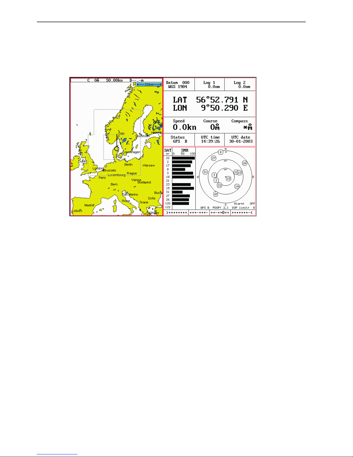
Chapter 4-6 CA34/44/54 Chart menu and INFO windows
4.3 Chart custom screens
The two custom screens in the chart menu consist of multiple
window combinations e.g.:
The displays, which are not related to the chart function, can be
exchanged with a different one. It is also possible to change the right
half of the screen from two quarter windows to half screen window,
and vice versa. See section 2.1.2 how you go about changing the
displays.
Page 63

CA34/44/54 Chart menu and INFO windows Chapter 4-7
4.4 Chart quick menu
Access the chart quick menu from active chart display. The functions available depends on the actual situation - refer to sections 4.4.1
to 4.4.7.
4.4.1 Cursor inactive
ENT
With chart in active window, and with cursor off, press [ENT] to call
up the quick menu with the following to choose from:
Scale: 1:6600000 Actual chart scale
No user data
at ship’s position
1
Edit user data
Inactive function
2
Chart info
Refer to Appendix C
3
Find nearest port services
Refer to Appendix C
4
Bearing and dist from A to B
Inactive function
5
Lock cursors
Inactive function
0
Ship to center
PAGE
More user data
MENU
Exit
Exit info window
0
Ship to center will update the chart and place the ship’s position in
the center of the chart display.
PAGE
More user data will toggle between available data on the ship’s
position.
Page 64

Chapter 4-8 CA34/44/54 Chart menu and INFO windows
4.4.2 Cursor active but not placed on any object or data
ENT
With chart in active window, and cursor active but not placed on any
object or user data, press [ENT] to call up the quick menu with the
following to choose from:
Scale: 1:6600000 Actual chart scale
No user data
at cursor position
1
Edit user data
Inactive function
2
Chart info
Refer to Appendix C
3
Find nearest port services
Refer to Appendix C
4
Bearing and dist from A to B
5
Lock cursors
0
Cursor to center
PAGE
More user data
Inactive function
MENU
Exit
Exit info window
4
Bearing & dist. from A to B will quickly provide the bearing and
distance from your current cursor position (A) to an arbitrary point
(B). Move cursor to point B and see the calculation in the small info
window. Press [CLR] to exit the function.
5
Lock cursors will lock the cursors in two chart displays on the same
screen and thus make the cursor movements synchronized. To return
to individual cursor control in each chart display, press [ENT], [5] to
‘Release cursors’ again. See also ‘Lock cursors’ in Appendix A.
0
Cursor to center will update the chart and place the cursor position
in the center of the chart display.
Page 65

CA34/44/54 Chart menu and INFO windows Chapter 4-9
4.4.3 Cursor placed on waypoint
ENT
With chart in active window, and cursor placed on a waypoint, press
[ENT] to call up the quick menu with the following to choose from:
WP found
Name: WP 1
LAT 57°15.504N
LON 9°17.249E
1
Edit user data
2
Chart info
Refer to Appendix C
3
Find nearest port services
Refer to Appendix C
4
Bearing and dist from A to B
Refer to section 4.4.2
5
Lock cursors
Refer to section 4.4.2
0
Cursor to center
Refer to section 4.4.2
PAGE
More user data
MENU
Exit
Exit info window
1
Edit user data opens a new info window:
Waypoint
1
Edit
Edit name, symbol, color etc.
2
Move
Move waypoint with cursor
CLR
Delete
Delete waypoint
MENU
Exit
Exit info window
PAGE
More user data will toggle between available data on cursor’s posi-
tion
Page 66

Chapter 4-10 CA34/44/54 Chart menu and INFO windows
4.4.4 Cursor placed on route leg or line section
ENT
With chart in active window, and cursor placed on a route leg or line
section, press [ENT] to call up the quick menu with the following to
choose from:
Route leg found: 5-6
Name: RTE 1
Leg: B130° 34.26nm
Total: 5 legs 143.1nm
1
Edit user data
2
Chart info
Refer to Appendix C
3
Find nearest port services
Refer to Appendix C
4
Bearing and dist from A to B
Refer to section 4.4.2
5
Lock cursors
Refer to section 4.4.2
0
Cursor to center
Refer to section 4.4.2
PAGE
More user data
MENU
Exit
Exit info window
1
Edit user data opens a new info window:
Route leg
1
Edit leg
Open new info window to edit route leg
2
Insert point
Move cursor to insert new point
3
Edit
Open new info window to edit route
CLR
Delete
Delete the whole route
MENU
Exit
Exit info window
PAGE
More user data will toggle between data on routepoint and route
leg.
Page 67

CA34/44/54 Chart menu and INFO windows Chapter 4-11
4.4.5 Cursor placed on routepoint or linepoint
ENT
With chart in active window, and cursor placed on a routepoint or
linepoint, press [ENT] to call up the quick menu with the following
to choose from:
Routepoint found 5
Name: RTE 1
From start: 108.8nm
To end: 34.26nm
1
Edit user data
2
Chart info
Refer to Appendix C
3
Find nearest port services
Refer to Appendix C
4
Bearing and dist from A to B
Refer to section 4.4.2
5
Lock cursors
Refer to section 4.4.2
0
Cursor to center
Refer to section 4.4.2
PAGE
More user data
MENU
Exit
Exit info window
1
Edit user data opens a new info window:
Routepoint
1
Edit point
Open new info window to edit routepoint
2
Move point
Move point with cursor
CLR
Delete point
Delete routepoint
3
Add point
Add point to route - in beginning or at end.
4
Edit
Open new info window to edit route
5
Delete
Delete the whole route
MENU
Exit
Exit info window
PAGE
More user data will toggle between data on routepoint and route leg
Page 68

Chapter 4-12 CA34/44/54 Chart menu and INFO windows
4.4.6 Cursor placed on trackpoint
Trackpoints are not as easily recognized as Routepoints, you may
have to move the cursor along on the track to locate a trackpoint.
ENT
With chart in active window, and cursor placed on a trackpoint,
press [ENT] to call up the quick menu with the following to choose
from:
Trackpoint found 3
Name: TRACK 1
Total: 836 points
1
Edit user data
2
Chart info
Refer to Appendix C
3
Find nearest port services
Refer to Appendix C
4
Bearing and dist from A to B
Refer to section 4.4.2
5
Lock cursors
Refer to section 4.4.2
0
Cursor to center
Refer to section 4.4.2
PAGE
More user data
MENU
Exit
Exit info window
1
Edit user data opens a new info window:
Trackpoint
CLR
Delete point
Delete trackpoint
1
Delete points from A to B
See below
2
Edit
Open new info window
3
Delete
Delete the whole track
MENU
Exit
Exit info window
Press [1] to delete points from A to B - move cursor to point B, and
press [ENT] to delete all trackpoints between cursor position on
chart and point B.
PAGE
More user data if cursor is placed on a MOB track you can toggle
between data on MOB symbol and data on MOB track. The symbol
and track are edited separately.
Page 69

CA34/44/54 Chart menu and INFO windows Chapter 4-13
4.4.7 Cursor placed on target
ENT
With chart in active window, and cursor placed on a target symbol,
press [ENT] to call up the quick menu with the following to choose
from:
Target fou nd
Name: TARGET 1
LAT 57°02.825N
LON 7°45.555E
1
Edit user data
2
Chart info
Refer to Appendix C
3
Find nearest port services
Refer to Appendix C
4
Bearing and dist from A to B
Refer to section 4.4.2
5
Lock cursors
Refer to section 4.4.2
0
Cursor to center
Refer to section 4.4.2
PAGE
More user data
MENU
Exit
Exit info window
1
Edit user data opens a new info window:
Target
1
Edit
Edit name, color, position etc.
2
Move
Move point with cursor
CLR
Delete
Delete target
MENU
Exit
Exit info window
PAGE
More user data will toggle between available data on cursor’s posi-
tion
Page 70

Chapter 4-14 CA34/44/54 Chart menu and INFO windows
4.4.8 GOTO menu
GOTO
Call up the GOTO menu with access to navigation modes:
Select NAV mode To select “Cursor” navigation will require
that the chart cursor is active.
“Waypoint”, “Route” and “Track” navigation requires that a waypoint, route or
track is stored in the memory.
1
Cursor
2
Waypoint
3
Route
4
Track
5
Anchor guard
MENU
Exit
For further details on the different NAV modes, refer to section 6.9
Navigation examples.
Anchor guard - when setting anchor, a pre-set alarm distance will
be activated, so in case the ship is drifting too far away from the
anchored position, the system will initiate a visual and acoustic alert
- refer to section 6.10 Anchor guard.
If pressing the [GOTO] key while one of the NAV modes is active,
this pop-up window will appear on the screen:
Navigation is ON
1
Advance
2
Restart to approaching point
3
Turn NAV OFF
MENU
Exit
Press [1] to advance to next waypoint in the route (Route navigation).
Press [2] if you for some reason have drifted off course and wish to
restart navigation from your actual position to the approaching point.
Page 71

CA34/44/54 Chart menu and INFO windows Chapter 4-15
4.4.9 PLOT menu
The CAXX is designed to make navigation easy and safe. Waypoints
can easily be plotted with a single keystroke, or be inserted via the
keypad. Making routes and drawing lines are done directly on the
chart. Very straightforward, uncomplicated and with a high level of
confidence as you can follow your actions ‘live’ on the chart.
PLOT
Call up the PLOT menu with the following to choose from:
PLOT new data
PLOT
Plot mark - ship
1
Insert mark - ship
2
Plot waypoint - cursor
3
Insert waypoint
4
Make route
5
Draw line
6
Plot target
7
Start track
8
Stop track
9
Set vertical mark
MENU
Exit
PLOT
From any display: Plot and save mark on ship’s position, including
actual depth indication. Preset name sequence: SHIP 1, SHIP 2 etc.
1
From any display: Plot and save waypoint. Ship’s position is sug-
gested, but you can key in a new position from keypad, change the
location name (cf.section 2.6), or change the symbol (cf.section 2.5)
and the color (select with +/- keys). Any changes made will be new
presets for plotting/insertion of ship’s position.
2
From active chart display with cursor on: Plot and save cursor posi-
tion as a waypoint. Preset name sequence: WP 1, WP 2 etc.
3
From any display: Plot and save waypoint. The position coordinates
are filled with zeroes, so you can key in the position you want from
Page 72

Chapter 4-16 CA34/44/54 Chart menu and INFO windows
the keypad, change the location name (cf.section 2.6), or change
the symbol (cf.section 2.5) and the color (select with +/- keys). Any
changes made will be new presets for plotting/insertion of the cursor
position.
- From active chart display with cursor on: Same options as above,
except that the zeroes in the position coordinates have been
exchanged with the cursor position.
- From active echo display: Plot and save waypoint from echogram.
Move cursor and press [ENT] to register spot as waypoint, including
actual depth indication. Name, symbol, color etc. can be changed.
4
From active chart display with cursor on: You can quickly make a
route by means of the cursor and the [PLOT] key. The present cursor
position will be the first position of the route you are about to make.
Move cursor to next position, and press [PLOT]. Continue in this
manner until the route is completed.
Existing waypoints can be used for making the route, simply by
placing the cursor on the waypoints and plot the positions. In case
you make a wrong plot, press [CLR] to erase the last plotted position. Save the route with [ENT] or exit the function with [MENU] to
abandon the route.
Do not use the exact position of buoys, markers etc. as waypoints
and routepoints. The high accuracy of the system may result in a collision when sailing in the dark or navigating with an autopilot.
5
From active chart display with cursor on: To draw lines or to make a
route is the same procedure, please see above.
6
From active chart display: With cursor on, plot target at cursor posi-
tion and with cursor off, plot target at ship’s position.
After plotting the target it will be saved in the memory, and you can
edit the target later on, either via the menu (cf.section 8.7) or directly
from the chart (cf.section 4.4.7).
7
From any display: Call up info window to start track. To change
default values, see section 8.5.
8
From any display: Call up info window to stop track.
9
From active echo display: Plot vertical marker (line) at the current
ping in the echo display.
Page 73

CA34/44/54 Chart menu and INFO windows Chapter 4-17
4.5 Chart setup
The settings are dedicated to the chart in the active window and does
not affect the second chart in dual chart mode. See section 3.2.7 for
chart settings related to the RadarChart overlay.
ADJ
Load chart setup related to active chart
◄
GOTO
Presentation Dep
PLOT
►
Display mode FULL
Orientation NORTH UP
Rotation resolution 15°
Motion RELATIVE
Quick chart info ON
Cursor 5 min.time-limit ON
Auto chart select ON
Extended level range OFF
Show range WITH BACKGROUND
MENU
Exit Accept
ENT
The tabs indicate which groups are available in each display mode e.g.
the above example shows that in FULL display mode you have access
to the groups in black: General, Areas and User data. The two groups
in red i.e. Presentation and Depth are only adjustable in
CUSTOM
display mode. See further on in this chapter for more details.
+/-
Select display mode: FULL, CUSTOM, SIMPLE, FISHING, LOW,
GRID
PLOT
Go to the next group
GOTO
Step back to the previous group
Scroll up/down in the chart settings
∆
∆
General
Page 74

Chapter 4-18 CA34/44/54 Chart menu and INFO windows
+/-
Toggle between available settings
ENT
Confirm changes and return to chart, or...
MENU
Abandon Chart setup and return to chart without making any
changes
4.5.1 Display modes in the chart setup
There are 7 different display modes to choose from: FULL (default), CUSTOM,
SIMPLE, FISHING, LOW, GRID, and a special OVERLAY mode, which only
can be activated from the radar function - see section 3.2.7. When a group is
shown in red or a function is shown in light grey it means that it is not available in
the selected display mode. The default settings in the various display modes are:
Group: General - specification of chart display in general
The available functions are according to display example on previous page for
all display modes and any change of the default settings will be applied in all
display modes, except for GRID, which has three adjustable functions:
Motion = RELATIVE
Cursor 5 min. time-limit = ON
Show range = WITH BACKGROUND
Group: Presentation - specifies presentation of marine, land and chart topics
The default settings in this group are fixed in all display modes, except for
*Custom where it is possible by the user to turn a feature ON (shown on the
chart) or OFF (not shown on the chart), etc.
C-MAP features are not available in GRID display mode.
C-MAP features
Full *Custom Simple Fishing Low
Marine:
Names
Nav-Aids
Light Sectors
Attention Areas
Tides, currents
Nature of seabed
Ports
Tracks, routes
Buoys
Signals
ON
INT
ON
ON
ON
ON
ON
ON
ON
ON
ON
INT
ON
ON
ON
ON
ON
ON
ON
ON
ON
INT
OFF
ON
ON
OFF
ON
OFF
ON
ON
ON
INT
OFF
ON
OFF
ON
OFF
OFF
ON
ON
OFF
INT
OFF
OFF
OFF
OFF
OFF
OFF
OFF
OFF
.....continued next page....
Page 75

CA34/44/54 Chart menu and INFO windows Chapter 4-19
.....continued from previous page....
C-MAP features
Full *Custom Simple Fishing Low
Land:
Natural features rivers
Natural features
Cultural features
Landmarks
Chart:
Grid
Boundary lines
Mixing levels
Declutter
ON
ON
ON
ON
AUTO
AUTO
ON
ON
ON
ON
ON
ON
AUTO
AUTO
OFF
ON
ON
OFF
OFF
ON
AUTO
AUTO
OFF
ON
OFF
OFF
OFF
OFF
AUTO
OFF
ON
ON
OFF
OFF
OFF
OFF
AUTO
OFF
OFF
ON
Group: Depth - specifies the presentation of depth lines, levels, etc. on chart
The default settings in this group are fixed in all display modes, except for
*Custom where it is possible by the user to alter the features. The color indication for depth levels 1, 2 and 3 is determined by the color palette in the SETUP
menu.
C-MAP features are not available in GRID display mode.
C-MAP features
Full *Custom Simple Fishing Low
Soundings
Underwater objects
Depth Lines
Depth Lines>
Depth Lines<
Depth Areas
Depth
Level 1
Level 2
Level 3
ON
ON
ON
0000m
9999m
ON
0-002m
2-009m
9-MAX
ON
ON
ON
0000m
9999m
ON
0-002m
2-009m
9-MAX
ON
ON
ON
0000m
5m
ON
0-002m
2-009m
9-MAX
ON
ON
ON
0000m
9999m
ON
0-002m
2-009m
9-MAX
OFF
ON
OFF
0000m
5m
OFF
0-002m
2-009m
9-MAX
Page 76

Chapter 4-20 CA34/44/54 Chart menu and INFO windows
Group: Areas - specifies the presentation of different areas on chart.
The default settings in this group are the same for all display modes and any
change of the default settings will be applied in all display modes, except
GRID, which do not include C-MAP features. The features can be changed
from FILLED to CONTOUR:
C-MAP features
All display modes
Land areas
Depth areas
Caution areas
Dredged areas
FILLED
FILLED
FILLED
FILLED
Group: User data - user defined objects can be visible or invisible on chart
The default settings in this group are the same for all display modes and any
change of the default settings will be applied in all display modes.
Chart features Defaults and choice of settings
Waypoints
Non active waypoints ON
Waypoint names ON
Waypoint depths ON
Routes
Non active routes AS SELECTED
Route names ON
Tracks
Non active tracks AS SELECTED
Track names ON
Lines
Lines AS SELECTED
Line names ON
Targets
Targets AS SELECTED
Target names ON
All the features in the user data level
that are set as default to ON= shown
on chart, can be changed to OFF= not
shown on chart.
Non active routes and tracks, all lines
and all targets are default to:
AS SELECTED= the choices made
for a particular route etc via the menu
e.g. MENU, 6, 2, ENT, ENT - Edit
route, where ‘Course line’ can be set
ON or OFF.
‘AS SELECTED’ can also be changed
to ‘ALL ON’= shown on the chart,
or ‘ALL OFF’= not shown on the
chart.
Page 77

CA34/44/54 Chart menu and INFO windows Chapter 4-21
4.5.2 Description of chart features
Auto chart select - When sailing with ‘Auto chart select’ ON and cursor
turned off, the range will automatically change to match the chart which is
available. But when set to OFF, then the selected range will remain, also when
sailing ‘out of the chart’.
Boundary lines - will indicate available C-MAP chart areas.
Caution areas - can be set to FILLED or CONTOUR.
FILLED= The caution areas will be filled with a preset color from C-MAP.
CONTOUR= The caution areas will be shown with a contour line only and the
fill will be the same as the background/water color on the chart.
Cursor 5 min. time-limit - can be set ON or OFF. When set to ON, the chart
cursor will automatically turn off if not used in a period of five minutes.
Declutter - when set to ON there will be no overlapping text on the chart e.g.
Names, Spot soundings etc.
Depth: Level 1, 2 and 3 - are identified by different colors. The number of
meters in the levels can be changed. The colors are preset in the Palette setup.
Depth areas - can be set ON or OFF= Not shown on chart.
FILLED - the depth areas will be filled with the color preset in the Palette
setup.
CONTOUR - the depth areas will be marked by a contour line only, and the
fill will be the same as the background/water color on the chart.
Depth lines - can be set ON or OFF= Not shown on chart.
Dredged areas - can be set to FILLED or CONTOUR.
FILLED= The dredged areas will be filled with a preset color from C-MAP.
CONTOUR= The dredged areas will be shown with a contour line only, and
the fill will be the same as the background/water color on the chart.
Extended level range - will enable changing range 3-4 steps within the same
chart level after having selected the range via a numeric key.
Grid - the LAT/LON grid can be set to ON or AUTO
ON= The LAT/LON grid will be visible on the chart display all the time.
AUTO= The LAT/LON grid will appear on the chart display when there is no
actual chart available in the selected scale.
The color of the grid is preset in the Palette setup.
Page 78

Chapter 4-22 CA34/44/54 Chart menu and INFO windows
Land areas - can be set to FILLED or CONTOUR.
FILLED= The land areas will be filled with a preset color in the Palette setup.
CONTOUR= The land areas will be shown with a contour line only and the
landfill will be the same as the background/water color on the chart.
Land settings -
can all be set ON=Shown on chart or OFF=Not shown on chart.
Marine settings
- can all be set ON or OFF, except for Nav-Aids which can be
set to INTERNATIONAL, INT. SIMPLIFIED, US, US SIMPLIFIED or OFF.
INTERNATIONAL - will present NavAids in ‘real life’ shapes and colors for
quick visual recognition (as per official INT1 standard paper chart presentation).
INT. SIMPLIFIED - the NavAids will be shown in generic symbols for minimum visual clutter on-screen.
US - will present NavAids in simplified shapes and real colors (as generally
found on NOAA paper charts).
US SIMPLIFIED - the NavAids will be shown in generic symbols for minimum visual clutter on-screen.
OFF - will shown no Nav-Aids on the chart.
Mixing levels - when set to ON, the number of blank chart areas will be
reduced, as the C-MAP library will find the missing area in a different level
to cover the blank area otherwise left on the screen. However, when using this
feature, chart re-draw time will be increased a little.
Orientation - can be set to NORTH UP, COURSE UP or NAV UP, and the
mode can be RELATIVE or TRUE motion.
NORTH UP - the chart will always be presented as north up.
COURSE UP - the chart will automatically turn, so your actual course (COG)
is up. If chart cursor is active it will stop the chart from rotating, press [CLR]
to turn cursor off. If a compass is connected, the reference will automatically
change to heading (compass).
NAV UP - the chart will automatically turn, so your bearing to destination is
up. If chart cursor is active it will stop the chart from rotating, press [CLR] to
turn cursor off.
RELATIVE motion - the ‘ship is positioned at the center of the screen and the
chart will move.
TRUE motion - the ‘ship’ will move across the chart.
Quick chart info - placing the chart cursor on a C-MAP object will activate a
small info window with details on the object. Info window will automatically
close after 10 seconds or when cursor is moved away.
Rotation resolution - can be set to adjust the chart for each 5, 10, 15, 20 or
25° changes in relation to present course or heading.
Page 79

CA34/44/54 Chart menu and INFO windows Chapter 4-23
Show range - can be set to WITH BACKGROUND, ON or OFF:
WITH BACKGROUND - will add a small line to the chart display indicating
that the length of the line equals a certain number of nautical miles/km - the
indication is highlighted with a background color.
ON - same as above, but without background color.
OFF - indication is not shown on chart.
Soundings -
can be set to ON or OFF.
ON - the information will be shown as selected i.e. in feet, fathoms or meters.
OFF - soundings are not shown on chart.
Underwater objects - can be set ON or OFF= Not shown on chart.
Page 80

Chapter 4-24 CA34/44/54 Chart menu and INFO windows
Page 81

CA34/44/54 Echo menu Chapter 5-1
5. Echosounder operation
The echosounder function of the CAXX determines the distance
between its transducer and underwater objects such as fish, lake
bottom or sea bed. It does this by utilizing the fact that an ultrasonic
wave transmitted through water travels at a nearly constant speed
of 4800 feet (1500 meters) per second. When a sound wave strikes
an underwater object such as fish or sea bottom, part of the sound
wave is reflected back toward the source. Thus by calculating the
time difference between the transmission of a sound wave and the
reception of the reflected sound wave, the depth to the object can be
determined.
The entire process begins in the display unit. Transmitter power is
sent to the transducer as a short pulse of electrical energy. The electrical signal produced by the transmitter is converted into an ultrasonic signal by the transducer and transmitted into the water. Any
reflected signals from intervening objects (such as a fish school)
are received by the transducer and converted back into an electrical signal. It is then amplified in the amplifier section, and finally,
displayed on the screen.
The picture displayed is made up of a series of vertical scan lines
(pings), one for each transmission. Each line represents a ‘snapshot’
of what has occurred beneath the boat. The series of snapshots are
accumulated side by side across the screen, and the resulting contours of the bottom and fish between the bottom and surface are
displayed.
Selecting echosounder displays
The CAXX provides various types of echosounder displays: standard echogram, bottom expansion (zoom), VRM expansion, and shift
mode. Each display has its special advantages. Select the appropriate setup for the echosounder display in the presentation “Setup”
and “Echosounder setup” displays, considering current sea area and
target fish.
Page 82

Chapter 5-2 CA34/44/54 Echo menu
5.1 Echo menu
3
ECHO
1
50kHz (or 38kHz CA44/54)
2
200kHz
3
Dual Frequency (CA44/54)
4
Custom screen 1
5
Custom screen 2
Low and high frequency echosounder display can be set up separately. The low frequency display will show deep water bottom
contours, and the high frequency display will show the mid-water
section with trawl targets or bait fish in a higher resolution.
The Dual Frequency display (CA44/54) will provide both the 50kHz
and the 200kHz echo displays in one screen.
The two custom screens will present multiple window combinations (section 5.2), where one of the main echo displays i.e. 50kHz or
200kHz will be fixed in the left half of the screen. Adjustments can
be made individually to both displays (section 5.7).
To access one of the displays via the menu e.g.:
MENU
Call up the menu bar, and...
3,2
press [3] and [2] to call up the Echo display for 200kHz in full
screen - see display example on next page.
5.2 Shortcut to the pages in the echo-series
The ECHO function is one of the main functions in the CAXX. Each
page under the [ECHO] key will include a window representing the
echo function. It is not possible to exchange main function displays
with a new display. Refer to section 2.1, 2.1.1 and 2.1.2 for further
information on the display and page system.
Page 83

CA34/44/54 Echo menu Chapter 5-3
From any display:
ECHO
Long press on the [ECHO] key will toggle between:
Standard
Dual Frequency
Custom screen 1 Custom screen 2
(CA44/54)
5.3 Standard echo display
This is the basic presentation mode (standard display) for observing
fish schools and sea bed. Some surface noise may appear just below
the transmission line.
Transmission line.
Time scale.
Depth range is adjustable with +/- keys or
the Quick-range keys
1-9.
Press key 0 to return
to Auto range.
The data field is preset to show: Gain level, Frequency, Transmit
Pulse length A- SHORT (set to AUTO), Transmit Power A- 10W
(set to AUTO) - see section 5.7.
Water temperature T in Celcius or Fahrenheit (in 1/10 degrees),
water or SOG speed S in knots or kilometers/hour or miles/hour,
actual depth *DK - units can be changed in Setup for units
(MENU,7,1).
*) Actual depth i.e. Depth below Keel/Surface/Transducer - settings
can be changed in Echosounder setup (MENU,7,ECHO).
Page 84

Chapter 5-4 CA34/44/54 Echo menu
1-9
Select range in 9 steps
+/-
Adjust range with the + and - keys
0
Activate Auto range
Press cursor left/right to adjust gain
ADJ
Direct access to Setup display related to active echo display 50kHz
or 200kHz - (see section 5.7)
Use the cursor to go to the function you wish to change the value for
+/-
Toggle between available values
ENT
Confirm changes, or...
MENU
Abandon changes and exit Setup display
5.4 Variable range marker
The VRM (Variable Range Marker) refers to a horizontal black line
shown on the display screen. The user can measure the range to
targets shown on the display screen by use of the VRM. The depth
to the VRM can be seen in the top left side of the screen for a few
seconds after the VRM line is moved.
From active echo display:
Activate the Variable Range Marker function, and...
Move the VRM up/down
+/-
Adjust the range by means of the +/- keys
CLR
Turn VRM off again
Page 85

CA34/44/54 Echo menu Chapter 5-5
5.5 Echo quick menu
A number of echo features can easily be accessed from the Echo
quick menu.
From active echo display:
ENT
Call up the Echo quick menu with access to the following features:
Echo quick menu
1
Change frequency
2
Hide A-scope
3
Standard echo display
4
Bottom lock display
5
Zoom display
6
Shift display
ECHO
Transmit power off
MENU
Exit
1
Change frequency will toggle between 38 (CA44/54), 50 or 200 kHz
displays (Airmar transducers) to suit the task. 200 kHz is for general
purpose and offers optimum discrimination and a narrow transmitter beam. 38/50 kHz is for searching in a wider area, determining
bottom conditions and going the deepest.
2
Activate/Hide A-scope The amplitude scope at the right side of the
echo display indicates the precise amplitude or strength of the last
received ping (sounding), which often can be used for determining
individual species of fish or hardness of the bottom.
3
Standard echo display Return to the basic presentation mode (stand-
ard display) from echo display with an added feature e.g. bottom
expansion, VRM expansion, etc.
4
Bottom lock display The advanced bottom lock and expansion
feature ensures a reliable depth readout and provides a compressed
standard display in the upper half of the display. The bottom area
can be magnified for better separation of echoes. The actual range of
Page 86

Chapter 5-6 CA34/44/54 Echo menu
the expansion window can be adjusted in the Setup display.
5
Zoom display This feature will provide an expanded view of the
area near the *Variable Range Marker which will give a better separation of echoes. The actual range of the expansion window can be
adjusted in the Setup display.
*) see section 5.4.
6
Shift display This feature can be applied when operating in deep
waters and select the range for an expansion window. The expansion
window can automatically follow a changing bottom or be set manually by the +/- keys.
ECHO
Transmit power off Stop transmission in order to observe noise
picked up by the transducer.
MENU
Abandon the Echo quick menu without making any changes
5.6 Plot waypoint or event mark via PLOT menu
From active echo display:
PLOT
Call up the PLOT menu with the following to choose from:
9
Set vertical mark will plot a vertical marker (line) at the current ping.
- or you can plot the position of a given echo on the chart:
3
Insert waypoint will activate a cursor on the echo display
Move cursor to the echo which position you wish to place as a way-
point
ENT
Press [ENT] to register the waypoint on the echo display
A new info window will open where you can change the name of the
waypoint, adjust the position if necessary, change symbol and color
of the waypoint. When satisfied with the information in the info
window:
ENT
Press [ENT] to save waypoint
Page 87

CA34/44/54 Echo menu Chapter 5-7
5.7 Presentation setup
The general Echosounder setup e.g. Selecting transducer, Alarm settings, Demo mode etc. is placed in the SETUP menu (section 9.3).
The echo setup in this chapter are the most common settings for
adjusting the presentation of the high or low frequency echo picture,
and can be accessed by a single keystroke.
ADJ
Press [ADJ] from active echo display
Setup 200kHz:
Range start: 000 m
Range: AUTO 25 m
Gain: 050%
White line: OFF
Expansion window: 6 m
TVG: Normal (20 log R)
Ping to ping filter: ON
Signal threshold: OFF
Color threshold:
OFF
Depth grid: OFF
Transmit pulse length: AUTO
Transmit power: AUTO
Scroll synchronization: TIME
Scroll speed: HIGH
Use the cursor key to move cursor around in the display
0-9
Key in new figures, or...
+/-
Toggle between available values
ENT
Confirm changes, or...
MENU
Abandon changes and exit display
Range start – allows the user to set the displayed depth range to
begin at some point below the surface. For example, a 100 meter displayed range can be “phased” downwards, so that the screen shows
a 100 meter section beginning at, say, 200 meters and going to 300
meters depth.
Range – refers to the distance shown from the top to the bottom of
Page 88

Chapter 5-8 CA34/44/54 Echo menu
the display screen. Selecting Auto range will cause the CAXX to
change the basic range setting(s) to keep the displayed bottom in
the lower half of the display. For instance, as your boat moves into
deeper waters, the system will automatically switch to a deeper
range, always keeping the displayed bottom in the lower half of the
display. Manual range allows the operator to set the range displayed
on the screen.
Gain – is another way of saying “sensitivity”, or possibly “volume”.
Increasing the gain setting of the CAXX will allow you to see smaller
and deeper targets. If the gain is set too high, however, you will begin
to see “noise” and unwanted targets. Generally speaking, you want to
set the gain control just below the point that you begin to see speckles
of “noise” between surface and the bottom on the screen.
White line – is a control which places a white/black line at the
displayed sea floor and blanks out 4 pixels just below the line. The
purpose of this is to help the user detect targets, such as fish, which
are very close to the sea floor and whose echoes tend to merge with
those of the sea floor itself.
Expansion window (zoom level) – can be selected in eight steps,
ranging from 1 to 50 meters, or converted to feet or fathoms (refer to
Setup for units, section 9.5). This function allows you to take a closer
look at a particular section of the water underneath your boat. You
can expand the view near the bottom (Bottom expansion) or near the
Variable Range Marker (VRM expansion).
TVG – Time Varying Gain – is a control that allows the CAXX to
make corrections for most of the losses and absorption that occurs as
sound energy passes through sea water. There are three settings to
choose from, Normal, Special and OFF.
The setting “Normal (20 log R) is for general fish finding at depths
down to 50m (150’) and it will also give a uniform bottom echo presentation at shallow, mid and deep water.
The setting “Special (40 log R) will adjust the TVG to show the same
echo strength for a given size fish at varying depths.
The OFF position is used for net sounders. In OFF position the TVG
is inactive which means that the sounder operates with a fixed gain
between each transmitter pulse. Auto range is switched to manual.
Ping to ping filter – can be set to either on or off. With the filter
“off”, then each received echo will be reflected on the screen.
Whereas with the filter “ON”, the system will compare every two
Page 89

CA34/44/54 Echo menu Chapter 5-9
echoes received and only reflect on the screen what is received from
both echoes, which will give a more uncluttered recording.
Signal threshold – can be set to ON to eliminate the appearance
of unwanted noise. The threshold level is automatic and the feature
should be used with caution, as it may eliminate small fish and small
unidentified objects on the screen.
Color threshold – the color threshold function allows the “weaker”
targets and noise which may be shown on the display screen to be
eliminated from the display. These targets are usually shown in the
weaker target colors such as blues and greens. The Color threshold allows you to choose not to display the blues, or the blues and
greens, etc. Doing this will leave only the stronger targets on the
display screen.
Depth grid - enables a more precise reading of depth and target relations across the screen.
Transmit pulse length – can be set OFF to observe noise in the
water (Auto range will switch to manual mode). Set to AUTO, the
optimum setting will be applied according to the water depth. Or it
can be set manually, if a specific pulse length is required:
SHORT less than 10m deep water
MEDIUM between 10 and 50 m deep water
LONG more than 50m deep water
A long pulse will reach deeper but give less resolution.
Transmit power – should normally be left on AUTOmatic.
CA34 settings are: AUTO, 600W, 100W, 10W and OFF.
CA44/54 settings are: AUTO, 1000W, 500W, 100W, 10W and OFF.
Scroll synchronization – the screen can be updated on the basis of
time or distance (when data from last ping appears on the display).
Scroll speed – is the ping rate and movement of the presentation of
echoes on the screen, moving from right to left. It is adjustable (Low,
Medium, High, Freeze), to allow the user to show a longer “history”
on the display screen, if desired.
Page 90

Chapter 5-10 CA34/44/54 Echo menu
5.8 How the echosounder works
When the CAXX is turned on, a transmitter begins
to send electrical pulses to the transducer. The
ceramic resonators in the transducer has a special
property which enables it to change dimensions
slightly when a varying voltage is applied.
The voltage is thus converted to mechanical vibrations (sound waves) which are then transmitted down
through the water.
See Fig. 1.
Fig. 1 Transmi ed ‘ping’
from the transmi er/receiver.
The sound waves move through the water until they
encounter a change in density, such as a fish or the
bottom. This causes the sound waves to ‘echo’ back
up through the water. When the reflected sound
waves (echoes) hit the transducer, the ceramic disk
vibrates at the same frequency. This generates a
varying voltage between the disk surfaces. This voltage goes back up through the cable to the receiver.
The CAXX amplifies and processes the signals and
presents them on the display screen.
See Fig. 2.
Fig. 2 The up arrow indicates:
Echo returning to the receiver.
The down arrow indicates:
Transmi ed pulse.
Page 91

CA34/44/54 Echo menu Chapter 5-11
5.9 Transducer beamwidth
The transducer mounted to the hull of your vessel serves as both
a ‘speaker’ when transmitting, and as a ‘microphone’ when the
echosounder is receiving. Similar to the way a flashlight focuses
light, most of the sound from your transducer is focused downwards
with a smaller amount going out to the sides. The amount of focusing
of the sound beam is expressed as a ‘beamwidth’.
Transducer
Approximation of the sound
pattern below the transducer
This angle is the transducer’s
beamwidth
1/2 maximum intensity
Maximum intensity
Fig. 3 A representation of a transducer bemwidth.
The center of the sound beam is the most intense, then as you move
out towards the sides of the sound beam there is a point where the
intensity of the sound is half what it was in the center. The distance
moved is the ‘beamwidth’. See Fig. 3.
Page 92

Chapter 5-12 CA34/44/54 Echo menu
5.10 Effects of the vessel’s speed
The presentation of fish on the CAXX depends directly on the vessel’s speed, as well as on the depth of the fish. When the vessel is
at rest, the echo traces will appear stretched and flattened. As the
vessel’s speed becomes greater, the echo traces will become shorter
and more arched. The reason for this change in appearance is that as
the vessel speed increases, fewer number of sound ‘pings’ strike each
fish. A low vessel speed will provide the most accurate information
of where fish are loacted.
Page 93

CA34/44/54 Pilot menu & navigation examples Chapter 6-1
6. Pilot menu
4
PILOT
1
Highway - see section 6.2 & 6.2.1
2
Position - see section 6.3
3
Dual Speed - see section 6.4
4
ETA & AVN - see section 6.5
5
Trim & Highway - see section 6.6
6
Set & Drift - see section 6.7
7
Custom screen 1 - see section 6.8
8
Custom screen 2 - see section 6.8
See also section 6.10 Anchor guard, section 6.11 MOB navigation
and 6.9 Navigation examples.
All functions in the Pilot menu are relevant information to use for
navigation. The two custom screens will present multiple window
combinations (section 6.1), where the window in the top left quarter
of the screen will present a fixed display from the pilot menu.
To access one of the displays via the menu e.g.:
MENU
Call up the menu bar, and...
4,1
press [4] and [1] to call up the Highway display in full screen
6.1 Shortcut to the pages in the pilot-series
The PILOT function is one of the main functions in the CAXX.
Each page under the [PILOT] key will include a window representing the pilot function. It is not possible to exchange main function
displays with a new display. Refer to section 2.1, 2.1.1 and 2.1.2 for
further information on the display and page system.
Page 94

Chapter 6-2 CA34/44/54 Pilot menu & navigation examples
Press the [PILOT] key from any display to call up a display in the
pilot-series, and:
PILOT
Long press on the [PILOT] key will toggle between (default):
Highway Custom screen 1 Custom screen 2
From one of the pilot displays i.e. full screen and active window in
the top left quarter:
PILOT
Short press on the [PILOT] key will toggle between:
Highway Position Dual Speed
ETA & AVN Trim & Highway Set & Drift
The sequence of the six displays under the [PILOT] key is available
when a navigation mode is active. If no navigation mode is active,
then the ETA & AVN and the Trim & Highway displays will not be
present in the sequence.
Page 95

CA34/44/54 Pilot menu & navigation examples Chapter 6-3
6.2 Highway display and Navigation setup
MENU
Call up the menu bar, and...
4,1
load Highway display
When there is no navigation mode active, you will receive the
legend: NAVIGATION IS OFF.
Before starting out in one of the navigation modes, it may be a good
idea to check out the Navigation setup display and see if the default
settings will suit your need.
ADJ
Load Navigation setup
Navigation setup:
Anchor alarm distance: 00.50nm
WP circle alarm: 00.10nm OFF
WP and cursor navigation:
XTE alarm: 00.10nm ON
Navigation mode: RHUMBLINE
Route navigation:
XTE alarm: OFF
Auto waypoint shift: WP-circle
Track navigation:
XTE alarm: 00.10nm OFF
Auto trackpoint shift: WP-circle
Navigation mode: RHUMBLINE
+/-
Toggle between available values, or...
0-9
key in a new alarm limit
ENT
Confirm entry
Anchor alarm distance - When setting anchor, check/change the
preset alarm distance, etc., so you will be warned in case you drift
too far from the anchored position. The alarm distance can be set to
anywhere between 0.01 and 9.99nm. See also section 6.10 Anchor
guard. The alarm will automatically reset once you are inside the
limits again.
WP circle alarm - forms a circle around each waypoint, and the
alarm distance can be set to anywhere between 0.01 and 9.99nm.
Page 96

Chapter 6-4 CA34/44/54 Pilot menu & navigation examples
The waypoint alarm will be activated when you reach the circle
or the perpendicular line - WP line alarm - crossing through the
waypoint. When “Auto waypoint shift” is set to “WP-circle” it will
override the “WP circle alarm” function.
XTE alarm - forms a corridor along the ideal track. When crossing
one of the boundaries the XTE alarm will be activated.
The alarm will automatically reset once you are inside the limits
again. The alarm distance can be set to anywhere between 0.01 and
9.99nm.
In Route navigation the XTE alarm value can be specified for each
route leg - see section 8.2.
Navigation mode - RHUMBLINE navigation is used for shorter
distances, and GREAT CIRCLE for long trips, especially when
crossing at high latitudes. COMPOSITE navigation is used when all
the legs in a route are not set to the same navigation mode.
Auto waypoint shift - can be set to WP-circle, WP-line or OFF.
When set to WP-circle, the system will change to the next waypoint
in the route after passing the circle line (border).
When set to WP-line, the system will change to next waypoint in the
route after passing the waypoint line (border).
When “Auto waypoint shift” is set to WP-circle, then the alarm
function at the waypoint’s circle will not be activated.
Page 97

CA34/44/54 Pilot menu & navigation examples Chapter 6-5
6.2.1 Highway display when navigation mode is active
MENU
Call up the menu bar, and...
4,1
load Highway display
With navigation mode active, the highway display will provide a
graphical steering display:
Intended
track
between two
waypoints.
XTE alarm
lines - refer
to sec.6.2 for
alarm setup.
Ship’s position and
course in
relation to
intended
track.
C: Course over ground
X: XTE - Cross-track-error
S: Speed over ground
B: Bearing to approaching point
D: Distance to approaching point
V: Speed towards point
Route: Name/number of active route and aproaching routepoint
BN: Bearing to next point
TDG: Total distance to go to end of route
TTG: Total time to go to end of route
Page 98

Internal POS
15-03-2004
Chapter 6-6 CA34/44/54 Pilot menu & navigation examples
6.3 Position display
MENU
Call up the menu bar, and...
4,2
load the Position display
Datum currently
selected.
Trip log 1 and 2.
Position with three
decimals in minutes.
Speed over ground.
Course, magnetic or
true.
Depth or Compass
from external sensor.
UTC or local time and date
Time and date in UTC - Universal Time Coordinates - is equal to
standard time in London (GMT). UTC is not affected by the local
summertime adjustments.
Position update - if, for some reason, there is no position update
from GPS or external sensor, the displayed position will start to flash
and an alarm will be activated to alert the operator. Reset the ‘Position missing’ alarm by [CLR]. The alarm can be set ON/OFF - see
section 7.5. The displayed position will stop flashing once normal
position update is resumed.
Internal POS - indicates the source of position data i.e. Internal,
External or DeadReckoning.
GPS A - Status indicator for reception of satellites:
a (A)= good, b (B)= acceptable, c (C)= fair, or *= no update - see
also “Status indicator and accuracy” below.
With built-in or connected DGPS receiver:
dGPS= differential data received.
DGPS= differential data received and used for corrections.
SDGPS= satellite differential data received and used for corrections.
Page 99

CA34/44/54 Pilot menu & navigation examples Chapter 6-7
Status indicator and accuracy
Small letters (a,b,c,) indicate that SA is active, and the position
accuracy is expected to be better than 100 meters in 95% of the time.
Capital letters indicate that SA is OFF, and the position accuracy is
then expected to be 15 meters or better in 95% of the time.
dGPS indicates that differential data is received, either via built-in
differential receiver or from external receiver.
DGPS or SDGPS indicates that the position is corrected by the differential data. The accuracy will typically be 2-5 meters for DGPS
and 3-7 meters for SDGPS.
In order to utilize the high accuracy of the GPS system, it is necessary to align the lat/long calculations to the paper charts you are
using. Refer to Position display setup below.
When using C-MAP electronic charts, the datum will be aligned
automatically.
Position display setup
The general Position setup e.g. Display position as: LAT/LON,
Decca or Loran C, etc. is placed in the SETUP menu (section 9.4).
ADJ
From position display, press [ADJ] to load Position display setup:
Pos display setup:
Datum: 000: World Geodetic System 1984
Log 1: 00000.0nm
Log 2: 00000.0nm
Additional data: COMPASS
Go to the function you wish to change
CLR
Reset log
Page 100

Chapter 6-8 CA34/44/54 Pilot menu & navigation examples
0-9
Key in new values, or...
+/-
Toggle between available values
ENT
Confirm editing and return to the Position display
Datum - is preset to WGS 1984 (World Geodetic System 1984), but
can be changed to any of the 118 datums listed in Appendix B e.g.
to match old paper charts or trackplotter data from RS2500/RS4000
(datum #002 European 1950).
The position in the position display and NMEA output (GLL+GL2)
will refer to the selected datum. To select a new datum: place the
cursor next to “Datum” and key in a new number or go two spaces to
the right (000
) and leaf through the datum list with +/-.
The datum in the chart display is fixed i.e. WGS84.
Log - reset log or insert alternative start figure by altering the value
in the “Log 1” and/or “Log 2” line. Press [CLR] to reset the figure,
and press the numeric keys 0-9 to alter the figure.
Additional data - can be set to COMPASS, DEPTH or ANT.
HEIGHT.
COMPASS will show heading from connected sensor.
DEPTH will be shown from built-in echosounder.
ANT. HEIGHT will indicate the actual antenna altitude (height
above sea level).
 Loading...