

Page 1

A brand by Navico - Leader in Marine Electronics
Manual
Simrad BSM-2
Broadband Sounder Module
EN, DE, ES, FR, IT
Page 2

Disclaimer
As Navico i s continuously improving this product, we
retain the right to make changes to the product at any
time which may not be reflected in this version of the
manual. Please contac t your nearest distributor if you
require any further assistance.
It is the owner’s sole responsibility to install and use the
equipment in a manner that will not cause accidents,
personal injury or property damage. The user of this
product is solely responsible for observing safe boating
practices.
NAVICO HOLDING AS AND ITS SUBSIDIARIES,
BRANCHES AND AFFILIATES DISCLAIM ALL LIABILITY
FOR ANY U SE OF THIS PRODUCT IN A WAY THAT MAY
CAUSE ACCIDENTS, DAMAGE OR T HAT MAY VIOLATE
THE LAW.
Governing Language: This statement, any instruction
manuals, user guides and other information relating
to the product (Documentation) may be translated
to, or has been translated from, another langua ge
(Translation). In the event of any conflict betwe en any
Translation of the Documentation, the English language
version of the Documentation will be the official version
of the Documentation.
This manual represents the product as at the time
of printing. Navico Holding AS and its subsidiar ies,
branches and affiliates reserve the right to make
changes to specifications without notice.
Feedback from you
Your feedback is important and helps Navico ensure
that this manual is a valuable resource for all marine
technicians.
BSM-2 Installation manual | 1
ENGLISH
Page 3

2 | BSM-2 Installation manual
Compliance Statements
The BSM-2 Broadband Sounder™ Module c omplies with
the following regulations and standards:
FCC Part 15 CE compliant per EN60945 and EN 60529 C - Tick -
Warning
The user is cautioned that any changes or modifications
not expressly approved by the party responsible for
compliance could void the user’s authority to operate the
equipment.
This equipment has been t ested and found to compl y
with the limits for a Class B digital device, pursuant
to Part 15 of the FCC rules. These limits are designed
to provide reasonable protection against harmful
interference in a residential installation. This e q uipment
generates, uses and can radiate ra dio frequency energy
and, if not installed and used in accordance with the
instructions, may cause harmful interference to radio
communications. However, there is no guarantee that
the interference will not occur in a particular installation.
If this equipment does cause harmful interference to
radio or television reception, which can be determined by
turning the equipment off and on, the user is encouraged
to try to correct the interferen ce by one or more of t he
following measures:
Reorient or relocate the re ceiving antenna•
Increase the separation between the equipment and•
receiver
Connect the equipm ent into an outlet on a circuit•
different from that of the receiver
Consult the dealer or an experienced technician for•
help
Page 4

BSM-2 Installation manual | 3
ENGLISH
Industry Canada
Operation is subject to the following two conditions:
(1) this device may not cause interference, and
(2) this device must accept any interference, including
interference that may cause undesired operation of the
device.
Warranty
The warranty card is supplie d as a separate document.
In case of any queries, refer to our website.
Page 5

4 | BSM-2 Installation manual
Contents
Introduction .................................................. 5
About this manual .........................................5
The BSM-2 module layout ...............................5
Parts included in package ...............................6
Required tools and supplies ............................6
Installation and wiring .................................. 7
Mounting location ..........................................7
Securing BSM-2 module .................................8
Wiring .........................................................8
General ................................................8
Grounding the unit ................................9
Wiring diagram .....................................9
Terminal connections ........................... 10
Power connection ................................ 11
Transducers connection .......................11
Connecting the BSM-2 to your display .... 14
Trouble shooting .......................................... 16
Technical specication ................................ 17
Dimensional drawing ................................... 20
Spare parts and accessories ........................ 21
Spare parts ........................................ 21
Accessories ....................................... 21
Transducers ........................................ 21
Page 6
BSM-2 Installation manual | 5
ENGLISH
Introduction
About this manual
This document describes how to install the BSM-2 and
connect the unit to transducers and display units.
Separate installation instruction for transducers are
included with the transducer package.
The BSM-2 is compatib le with the following displays and
systems:
NSE NSO NSS -
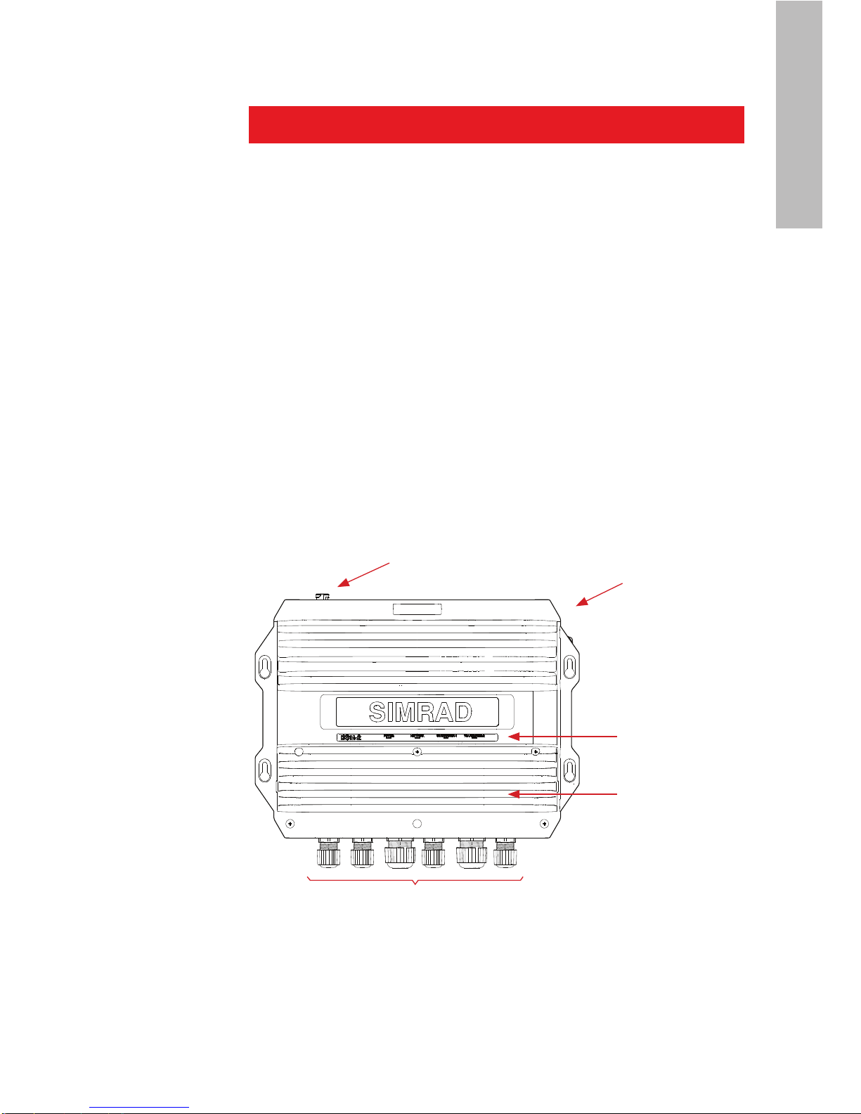
The BSM-2 module layout
rEMovABLE
CovEr
LED STATuS
INDICATorS
ETHErNET
CoNNECTor
WATErTIGHT
CABLE GLANDS
GrouNDING
SCrEW
Page 7
6 | BSM-2 Installation manual
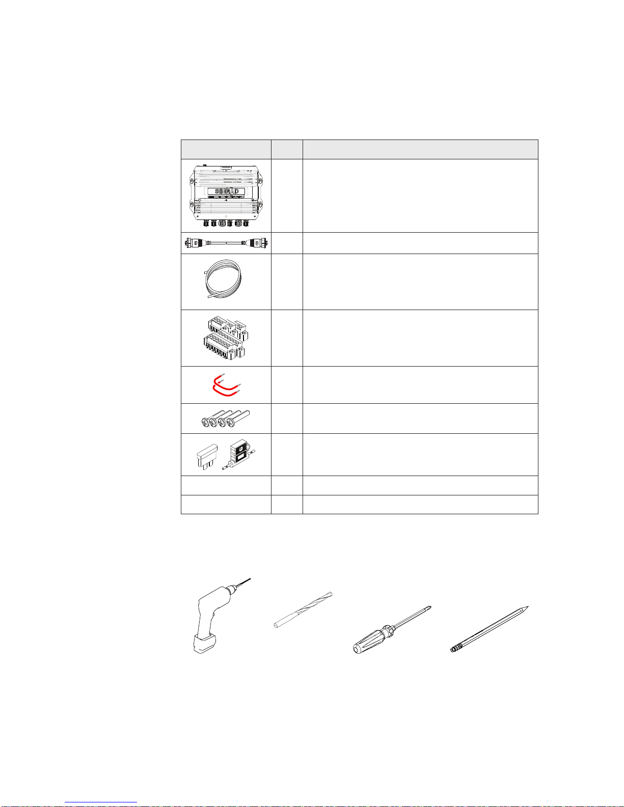
Parts included in package
For spare parts and part numbers, see Spare parts and
accessories page 21.
Item No. Description
1 BSM-2 sounder module
1 Ethernet adapter cable, 4.5 m (15 ft)
1
Power cable (bare wires), 2 m (6.5 ft)
Power and GND: 16 ga uges Switch connection: 18 gauges -
1
Terminal block connection kit, including;
6 Terminal blocks -
2 Jumper wires for impedance selection
4 Screws
1
Spare Fuse kit including;
3A Fuses and fuse holders -
1 Warranty c ard
1 This manual
required tools and supplies
Drill
2 mm
(5/64”)
Drill Bit Screw driver Pencil
Page 8
BSM-2 Installation manual | 7
ENGLISH
Installation and wiring
Mounting location
Before installing the BSM-2, consider location and cable
runs necessary to c onnect the module to display unit,
transducer and power so urce.
The mountin g location must allow for required working
area when connecting the cables. Also ensure that the
location allows viewing the unit’s LED indicators.
The units should be mounted with special regar d to the
units’ environmental protection, temperature range and
cable length.
The mountin g surface needs to be structurally strong,
with as little vibration as possible. If possible mount the
unit close to the edges o f a panel to minimize vibratio n.
Do not run the transducer cabling ne a r the BSM-2 power
cables, any VHF antenna coax cables or any DC or AC
power cables. Avoid placing Ethernet cables close to VHF
antennas.
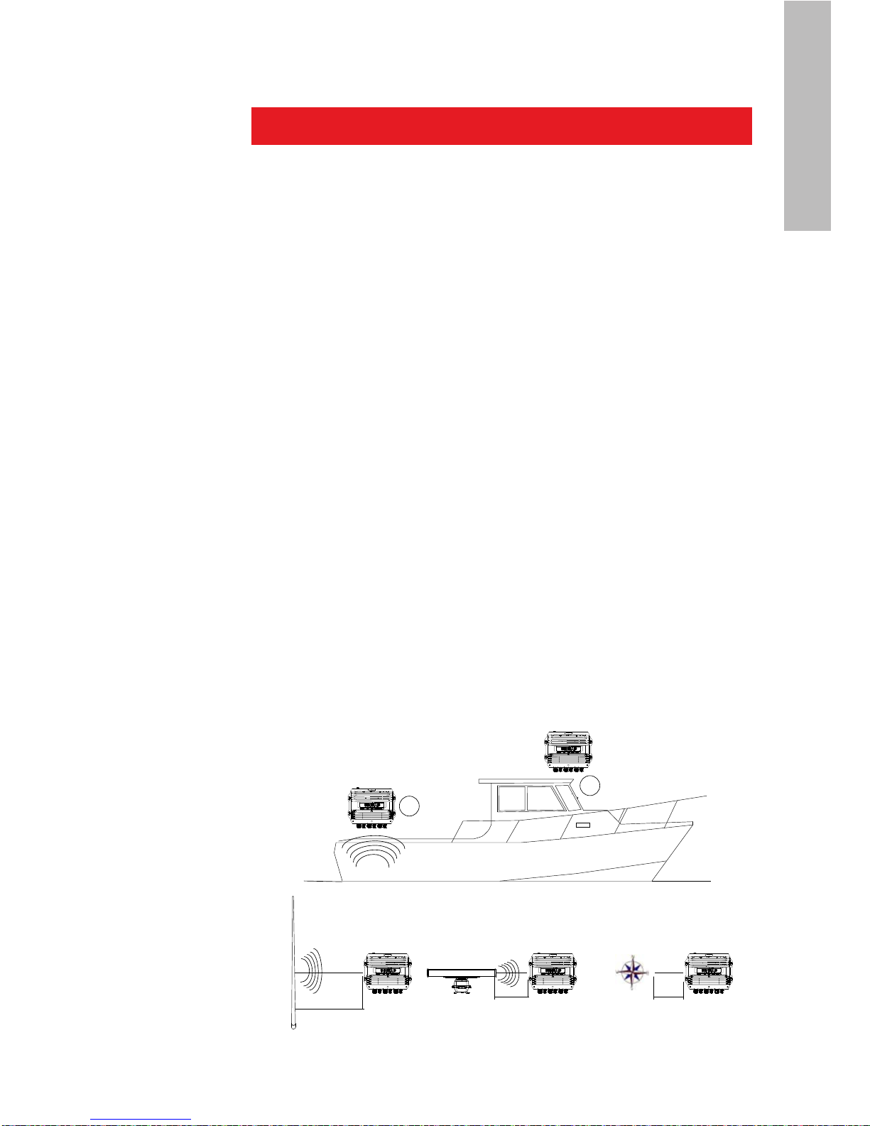
The BSM-2 conforms to the appropriate Electromagnetic
Compatibility (EMC) standards, but proper installation
is required to get best use and performance from
this product. Ensure you have as much separation as
possible between different electrical equipment, (see
diagram below).
X
X
Electromagnetic interference
Gasoline fumes
Vibration
Heat
Sunlight
Salt spray
Physical damage
2.0 m (6.5 ft) Min
1.8 m (6 ft) Min
1.5 m (5 ft) Min
RADAR
Radio or AIS Transmitter
Compass
Page 9

8 | BSM-2 Installation manual
Securing BSM-2 module
Mount the BSM-2 on a vertical surface with the power
and transducer cable entries exiting downwards.
Fasten the BSM-2 by using the 4 stainless steel self
tapping screws included with the unit.
Wiring
General
The power and the transducer
cables connect with screw
terminals inside the BSM-2
unit. Refer wiring diagram and
connection details on the following
pages.
The BSM-2 contains high voltages and specialized
parts; the operator should never remove the
module’s cover without removing the power
connection.
Removing the transducer cable from the BSM-2
while the module is powered on can cause sparks.
Remove the transducer cables only after the
module has been disconnected from its power
source.
Page 10

BSM-2 Installation manual | 9
ENGLISH
Grounding the unit
For additional safety install grounding cable in ground
screw hole as indicated on illustration. Recommended 16
awg wire.
Wiring diagram
BSM-2 NEP-2
12 - 24 V DC
+
_
1
3
2
ref Description
1 Ethernet cable
2 BSM-2 Power cable
3 Transducer cables
SINGLE
DISPLAy
SySTEM
MuLTIPLE
DISPLAy
SySTEM
TrANSDuCErS
Page 11

10 | BSM-2 Installation manual
Terminal connections
Select cable inl ets according to cable diameter and 1
labelling on the front plate
POWER
XDCR HI
XDCR LO
SPEED TEMP 1 TEMP 2
Cable Cable diameter
M20
Transducer 1 Transducer 2 -
10.0 mm - 14.0 mm
(3.94” - 5.51”)
M16
Power Speed Temperature 1 Temperature 2 -
6.0 mm - 10.0 mm
(2.36” - 3.94”)
2 Remove the outer sealing nuts from selected cable
glands, and thread those on to the cables
3 Terminate the wires to the terminal blocks
according to the terminal specication in the
following pages
Connect the terminal blocks to the pcb4
Tighten the outer sealing nuts by hand5
Close th e BSM-2 cover and secure the cables6
Page 12

BSM-2 Installation manual | 11
ENGLISH
Power connection
The unit has no power key and will turn on when power
is applied.
When used in an
NSE/NS S system, it
is recommended to
connect the BSM-2 to
the Power control bus,
and set display system
to power control
master.
If the BSM-2 is connected
directly to the vessel’s
battery, the module will
continue to draw power even
when it is not in operation. It
is recommended that the
yellow power cable wire be
fitted with an optional on/off
switch, allowing the BSM-2
to be power ed off when not
in use.
POWER
POS (+)
J3
1
NEG (-)
ACC PWR
1 3 42
Transducers connection
For a list of compatible tr a nsducers see Spare parts
and accessories page 21, or contact your dealer.
BSM-2
12 - 24 V DC
Red
Black
Yellow
Red
Black
Yellow
+
_
NSE
Power
Control bus
Blue
(n/c)
Blue
(n/c)
BSM-2
Switch
12 - 24 V DC
+
_
Red
Black
Yellow
Blue
(n/c)
rEF. CoLor FuNCTIoN
1 Yellow
Power control
(18 gauges)
2 Black
Battery (16 gauges)
3 Red
Battery +
(16 gauges)
4 Blue NC
Page 13

12 | BSM-2 Installation manual
Airmar transducers
The wiring diagram below shows how to connect an
Airmar transducer (R309).
On some mod els Low frequency XDCR+ wire (ye llow) can
be color blue/white.
On some transducer mod els temperature brown cable is
connected internally to XID GND, and there is no need to
connect bare and brown cable together.
Consult XDCR documentation for correct wiring d iagram
before connecting transducer!
rEF. CoLor FuNCTIoN
1 Orange XID
2 Shield XID ground (if available)
3 Brown Thermistor (XID ground)
4 White Thermistor
5 Shield High freq. depth shield
6 Black High freq. negat ive
7 Blue High freq. positive
8 Shield Low freq. depth shield
9 Black Low freq. negative
10 Yellow or blue/white Low freq. posi tive
XDCR LOW
SPD PWR
SPD IN
GND
SPEED
J4
1
XDCR HIGH
XDCR Z1
XDCR Z2
XDCR Z3
XDCR -
XDCR +
SHIELD
IMP SEL
J8
1
XDCR Z1
XDCR Z2
XDCR Z3
XDCR -
XDCR +
SHIELD
IMP SEL
J7
1
TEMP LOW
TEMP LOW
GND
XDCR ID LOW
J6
1
TEMP HIGH
TEMP HIGH
GND
XDCR ID HIGH
J5
1
9
10
5
6
8
7
1 2
3 4
Page 14
BSM-2 Installation manual | 13
ENGLISH
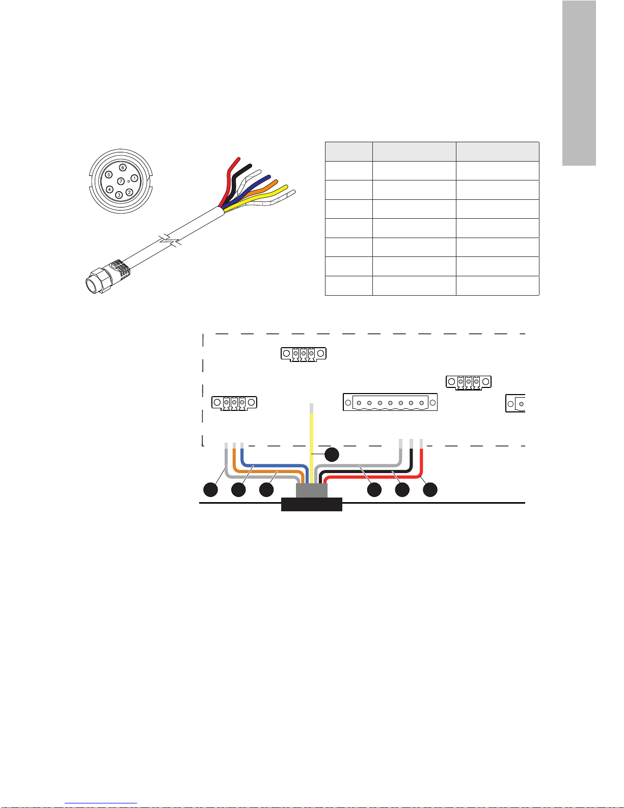
7 pins transducers
An optional transducer adapter cable is available
(000-10377-001) for connecting 7 pin transducers to the
BSM-2.
Front View
XDCR LOW
SPD PWR
SPD IN
GND
SPEED
J4
1
XDCR HIGH
XDCR Z1
XDCR Z2
XDCR Z3
XDCR -
XDCR +
SHIELD
IMP SEL
J8
1
XDCR Z1
XDCR Z2
XDCR Z3
XDCR -
XDCR +
SHIELD
IMP SEL
J7
1
TEMP LOW
TEMP LOW
GND
XDCR ID LOW
J6
1
TEMP HIGH
TEMP HIGH
GND
XDCR ID HIGH
J5
1
1
4
3 267 5
rEF. CoLor FuNCTIoN
1 Red XDCR+
2 Black XDCR3 XDCR Shield SHIELD
4 Yellow TEMP
5 Orange SPD IN
6 Blue SPD PWR
7 Shield GND
Page 15

14 | BSM-2 Installation manual
Strap settings for transducer impedance
Each transducer connector has 3
transducer impedan ce jumpers, used to
assure max power is being transferred
to the sonar elements.
The transducer list on page 21 shows
how to set the jumper for transducers
that can be used with BSM-2.
A
B
D
E
FC
XDCR HIGH
XDCR Z1
XDCR Z2
XDCR Z3
XDCR -
XDCR +
SHIELD
IMP SEL
J8
1
XDCR LOW
XDCR Z1
XDCR Z2
XDCR Z3
XDCR -
XDCR +
SHIELD
IMP SEL
J7
1
For any transducer not included in the list, connect
the jumper to the impedance s elector according to the
transducer impedan ce based o n the following table:
HIGH FrEQ LoW FrEQ
A 100 Ohm D 100 Ohm
B 270 Ohm E 270 Ohm
C 400 Ohm F 400 Ohm
If the Transducer impedance doesn’t appear in the table,
select the closest impedance that is higher than the
customers value.
Connecting the BSM-2 to your display
The BSM-2 connects to your display system over an
Ethernet network, either directly or via a Network
Expansion Port. Refer Cabling diagram, page 9.
When connected to an NSO, the RJ45 to 5 pin cross-over
Ethernet cable included with the NSO system must be
used.
For details refer t o the display system’s Installation
manual.
Page 16

BSM-2 Installation manual | 15
ENGLISH
Setting up the transducers
The BSM-2 is compatib le with Airmar’s Transducer ID
protocol. If you have an Airmar transducer that support s
this feature, BSM-2 will read your transducer’s
specification at start-up and automatically adjust the
frequency and temperature settings. The transducer’s
XID wire (orange) should be connected to the XDCR_ID_
HIGH/LOW terminal in the TEMP HIGH/LOW connector as
shown below.
TEMP HIGH
TEMP HIGH
GND
XDCR ID HIGH
J5
1
1
2
If your transducer doesn’ t support Airmar’s Transducer
ID protocol, the transdu cer selection and configuring
needs to be done from the display as shown on the
graphics below.
A detailed description is found in the relevant
documentation for the display.
rEF. CoLor SIGNAL
1 Orange XID
2 Shield XID GND
MENU WIN
x2
Page 17

16 | BSM-2 Installation manual
Trouble shooting
POWER NETWORK TRANSDUCER-2TRANSDUCER-1
IND. STATuS DESCrIPTIoN
Power
Off
No power connection
Check power and power cable
Check yellow wire On - Red System st arting
On - Green Sys tem operational
Flashing Red/Green
Software error or unit
reprogrammed
Restart the unit -
If still not ok contact -
Customer Support
Network
Off
No Ethernet connection
Check cable -
Verify that remote unit is -
turned ON
On - Green Ethernet connected and ok
Transducers
Off Transducer not connected
Flashing every
0.5 second Green
Initializing transmitter
Flashing every
second Green
Searching fo r bottom signal
On - Green Sys tem operational
Page 18

BSM-2 Installation manual | 17
ENGLISH
Compliance and Environmental
Compliance CE, C-TICK
Technical
Standards
IEC 60945,
IEC 60529
Waterproof IPX5
Humidity Up to 95% at 35°C non-
condensing
Storage
Temperature
–30°C to +70°C
Operating
Temperature
–15°C to +55°C
General
Connectors 6 Glands and 1 Ethernet Glands: Depth transducer
(x2), Temperatu re (x2), Speed
transducer, Power Connector: 5
pin Yellow RJ45
Weight 4.8 kg (10.6 lbs) Die Cast Aluminum
Dimensions
(WxHxD) mm/
in
340x100x289 mm
(13.38x3.94x11.37 inches)
With watertight glands and
connector outs i de dimensions
included
Mounting 4 keyholed mounting tabs Mount below deck but NOT in
engine compartment
Sonar Specications
Power Output 250 Watts RMS
2,000 Watts (peak to
peak)
With CHIRP; Transducer
dependent with 3 impedance taps
Power requirements
Power
Consumption
Range dependent –
norma lly less than 10W
3A internal fuse
Technical specication
Page 19

18 | BSM-2 Installation manual
Sonar Specications
Frequencies Broadband Frequencies
Transceiver High:
130- 210Khz; 40- 60Khz
Bro adband Frequencies
Transceiver Low:
40-60Khz; 25-45Kh z -
Narrowband Frequencies
Transceiver High:
200Khz; 50Khz -
Narrowband Frequencies
Transceiver Low:
50Khz; 38Khz; 28Khz -
Transmitter
and Receiver
Type
Dual Broadband Tuned
receivers
Dual Tuned CHIRP
Transmitters
Pulse Length Range Dependent - to
70ms max
CHIRP produc es 5X better
resolution
Impedance 3 taps Accommodates all narrowband
used on BSM-1, most Airmar
latest Broadband Transducers
and SIMRAD COMBI-C
Max. transmit
rate
Range dependent – to
20Hz in shallow depths.
User selectable.
2X, 4X, 8X scroll speed available
Range scales 5, 8, 10, 15, 20, 30, 40,
60, 80,100,120, 150, 200,
250, 300, 400, 500, 600,
700, 800, 900, 1000,
1500, 2000, 4000, 6000,
8000, 10,000, 12,000,
15,000
NOTE: all numbers above
in ft.
Can be changed to
metrics in NSE/NSO/NSS
unit.
To 15,000 ft, 2500 fa, 4500
meters
Sees digital depth to 10,000’ with
Airma r R309 28-45Khz
Page 20

BSM-2 Installation manual | 19
ENGLISH
Range control Auto/manual range with
zoom,
alternating dual frequency
display with CHIRP,
simultaneous with
narrowband
With Upper and Lowe r Limit
Zoom size Auto/manual x2, x3,
x4, x5, x6, x7, x8 (user
selectable)
DC voltage requirements
Voltage 10.7–32 VDC (for 12 or 24
VDC systems)
Interfaces
Network Ethernet 10/100 4 LED status indicators
Page 21

20 | BSM-2 Installa tion manual
Dimensional drawing
340 mm (13.38”)
320 mm (12.60”)
100 mm (3.94”)109 mm (4.29”)
250 mm (9.84”)
289 mm (11.38”)
Page 22

BSM-2 Installation manual | 21
ENGLISH
Spare parts and accessories
Spare parts
Part no. Description.
000-10411-001 Power cable
000-10412-001
Hardware mounting accessories including
4 screws;
8Gx1, PAN POZI, S/T, 16, LO-HEAD -
000-10414-001 Terminal block
Accessories
Part no. Description.
000-10377-001
7 pins Transducer Adapter Cable, female to
bare wires. 1.8 m (6 ft)
000-10386-001
700-3000 Combi C 1kW Thru Hull
50/200Khz with 10°x 16° and 7°x 7°
beamwidths Depth/Temp (same as
Kongsberg KSV-203005 50/200 Combi -D)
000-10387-001
700-3001 Combi C 1kW Th ru Hull
38/200Kh z with 13°x 21° and 7°x 7°
beamwidths w/HS Fairing Block Depth/
Temp (same as Kongsberg KSV-203004
38/200 Combi -D)
000-0127-51 Ethernet cable yellow 5 Pin 2 m (6.5 ft)
000-0127-29 Ethernet cable yellow 5 Pin 4.5 m (15 ft)
000-0127-30 Ethernet cable yellow 5 Pin 7.7 m (25 ft)
000-0127-37 Ethernet cable yellow 5 Pin 15.2 m (50 ft)
000-10029-001
NEP-2 Network Expansion Port (Yellow
connectors)
Transducers
The next pages includes a list of standard transducers.
Consult your dealer for more information.
Page 23

22 | BSM-2 Installation manual
Manufacturer Model Description
Frequency
(KHz)
Balance
load
TAP (ref
page 14)
Airmar
Narrow
Band
B744
Bronze Thru Hull 50/200Khz Depth/Temp/
Speed w 45/12˚ Beamwidths and high Speed
Fairing Block.
12 m (39.4 ft) cable
50 300ohms E
200 340ohms C
B164
Bronze Low Prole Thru Hull 1kW 50/200Khz
Depth/Temp w 22/20˚ 6/6˚ Array Beamwidths
and 12˚ tilt.
12 m (39.4 ft) cable
50 240ohms E
200 180ohms B
B258
Bronze Thru Hull 50/200Khz Depth/Temp
w 15/21˚ 3/5˚ Array Beamwidths and High
Speed Fairing Block.
12 m (39.4 ft) cable
50 225ohms E
200 200ohms B
B260
Bronze Thru Hull 50/200Khz Depth/Temp w
19/6˚ Beamwidths and High Speed Fairing
Block.
12 m (39.4 ft) cable
50 250ohms E
200 90ohms A
B260
(Diplexer)
Bronze Thru Hull 50/200Khz Depth/Temp w
19/6˚ Beamwidths and High Speed Fairing
Block. Depth/Temp
12 m (39.4 ft) cable
50 250ohms E
200 310ohms B
Page 24

BSM-2 Installation manual | 23
ENGLISH
Manufacturer Model Description
Frequency
(KHz)
Balance
load
TAP (ref
page 14)
Airmar
Broadband
B765
600W Bronze Thru Hull
40/60Khz with 20°-40° beamwidths
130/210Khz with 10°-16° beamwidths
w/HS Fairing block
Depth/Temp/Speed
12 m (39.4 ft) cable
50 (40-60) 100-250
Ohms
B
200 (130-210)
100-250
Ohms
E
B265
1kW Bronze Thru Hull
40/60Khz with 21°-31° beamwidths
130/210Khz with 6°-10° beamwidths
w/HS Fairing block
Depth/Temp
12 m (39.4 ft) cable
50 (40-60)
100 - 400
ohms
F
200 (130-210)
90 - 250
ohms
B
R209
3kW Thru Hull
33/60Khz with 6°-11° x 11°-17° beamwidths
130/210Khz with 5°-7° beamwidths
Depth/Temp
15 m (49.2 ft) cable
38 (33-60)
90 - 175
ohms
D
200 (130-210)
90 - 250
ohms
B
R299
3kW Tank Kit
33/60Khz with 6°-11° x 11°-17° beamwidths
130/210Khz with 5°-7° beamwidths
Depth only
15 m (49.2 ft) cable
38 (33-60)
90 - 175
ohms
D
200 (130-210)
90 - 250
ohms
B
Page 25

24 | BSM-2 Installation manual
Manufacturer Model Description
Frequency
(KHz)
Balance
load
TAP (ref
page 14)
Airmar
Broadband
cont.
R309
3kW Thru Hull
25/45Khz with 6°-11° x 11°-17° beamwidths
130/210Khz with 5°-7° beamwidths
Depth/Temp
15 m (49.2 ft) cable
28 (25-45)
135 - 270
ohms
E
200 (130-210)
90 - 250
ohms
B
R399
3kW Tank Kit
25/45Khz with 6°-11° x 11°-17° beamwidths
130/210Khz with 5°-7° beamwidths
Depth only
15 m (49.2 ft) cable
28 (25-45)
135 - 270
ohms
E
200 (130-210)
90 - 250
ohms
B
Simrad
50/200
Combi C
1kW Thru Hull
50/200Khz with 10°x16° and 7°x7°
beamwidths
Depth/Temp
50 75ohms D
200 75ohms A
38/200
Combi C
1kW Thru Hull
38/200Khz with 13°x21° and 7°x7°
beamwidths
w/HS Fairing block
Depth/Temp
38 75ohms D
200 75ohms A
 Loading...