

Simrad ARGUS FMCW 3G,ARGUS FMCW 4G User Manual
ARGUS RADAR
SYSTEM
User Manual
ENGLISH
navico-commercial.com

Preface
Disclaimer
As Navico is continuously improving this product, we retain the right to make changes to the
product at any time which may not be reflected in this version of the manual. Please contact
your nearest distributor if you require any further assistance.
It is the owner’s sole responsibility to install and use the equipment in a manner that will not
cause accidents, personal injury or property damage. The user of this product is solely responsible for observing safe boating practices.
NAVICO HOLDING AS AND ITS SUBSIDIARIES, BRANCHES AND AFFILIATES DISCLAIM ALL LIABILITY FOR ANY USE OF THIS PRODUCT IN A WAY THAT MAY CAUSE ACCIDENTS, DAMAGE OR
THAT MAY VIOLATE THE LAW.
Governing Language: This statement, any instruction manuals, user guides and other information relating to the product (Documentation) may be translated to, or has been translated
from, another language (Translation). In the event of any conflict between any Translation of
the Documentation, the English language version of the Documentation will be the official
version of the Documentation.
This manual represents the product as at the time of printing. Navico Holding AS and its subsidiaries, branches and affiliates reserve the right to make changes to specifications without
notice.
Approvals and Warranty
Please refer to the website: www.navico.com/commercial
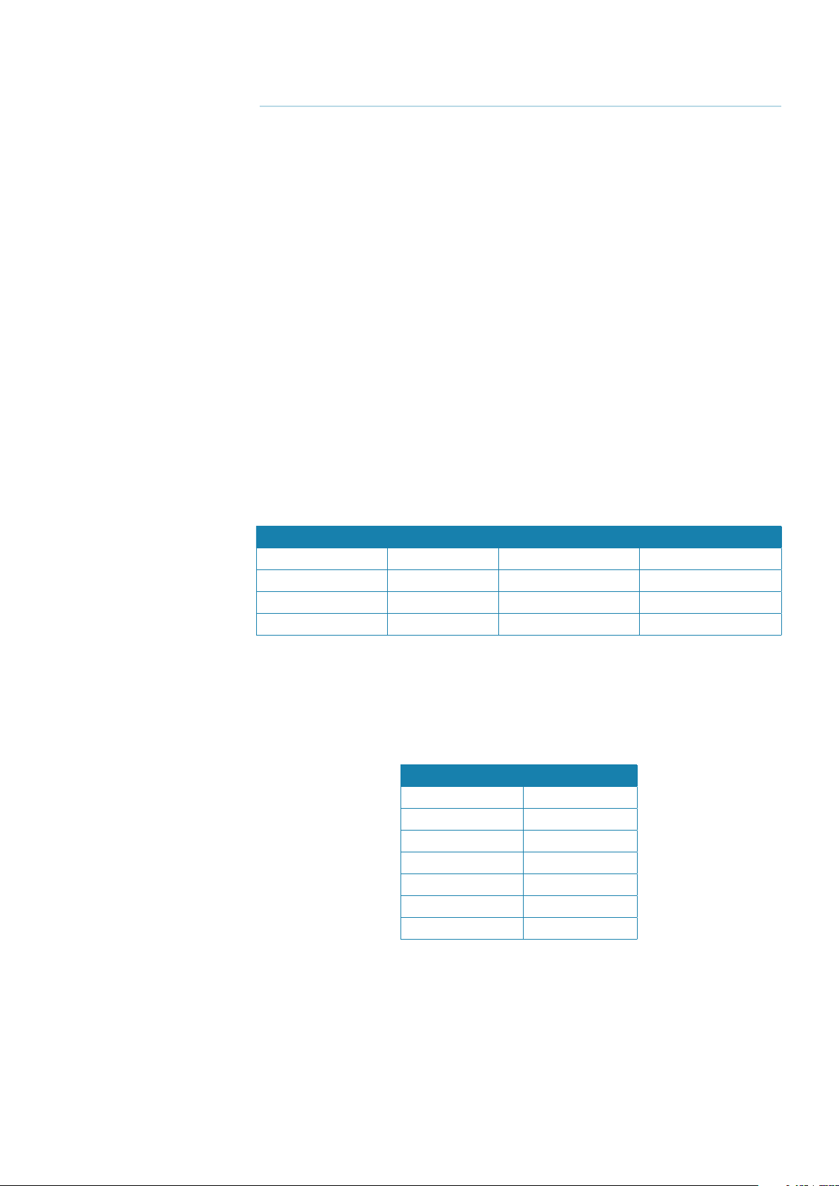
Record of changes
Part number/Rev. Date Purpose of change Requested by
988-10185-001 September 2011 First issue
988-10185-002 October 2013 Software release 3.2 M. Carmagnini
988-10185-003 October 2014 Software release 3.2.5 M. Carmagnini
988-10185-004 October 2016 Software release 3.3.2 M. Carmagnini
About this manual
This manual is a reference guide for operating the Argus radar system and describes the following software revision:
Software Edition SWC001A006
Release date: October 2016
MAIN : 3.3.2
ATA 3.2.6
IOVP 3.2.6
Video Proc. 1.7
Graph. Acc. 1.10
Control Panel 16/30
The manual will continuously be updated to match new software releases. The latest available
manual version can be downloaded from the website: www.navico.com/commercial
| Argus Radar Operator Manual
Preface
| 1
Safety precautions
The Argus radar is connected to 115 VAC or 220 VAC - 50 or 60 Hz power; therefore, before
starting any work on the equipment, make sure that the power supply is switched off.
The system is equipped with fuses protecting the electronics devices from short circuits,
which may damage the equipment or cause fire.
Depending upon the material to be highlighted, the following attention headings are used in
this manual:
Danger: Before turning on the radar, make sure that no one is standing near the an-
tenna.
Warning: The electronics of the equipment are supplied with mains power, also when
the equipment is switched off. For this reason, opening a unit must be performed only by
skilled personnel.
Warning: An operating or maintenance procedure, practice, condition and statement
which, if not strictly observed, could result in injury to personnel or death.
Unit
conguration
12 kW X-band +
6’ X-band antenna
12 kW X-band +
9’ X-band antenna
12 kW X-band +
12’ X-band antenna
25 kW X-band +
6’ X-band antenna
25 kW X-band +
9’ X-band antenna
25 kW X-band +
12’ X-band antenna
30 kW S-band +
12’ S-band antenna
Warning: An operating or maintenance procedure, practice, condition and statement
which, if not strictly observed, could result in damage to, or destruction of, the system or
reduced performance.
¼ Note: An essential operating or maintenance procedure, condition or statement, which must
be noticed.
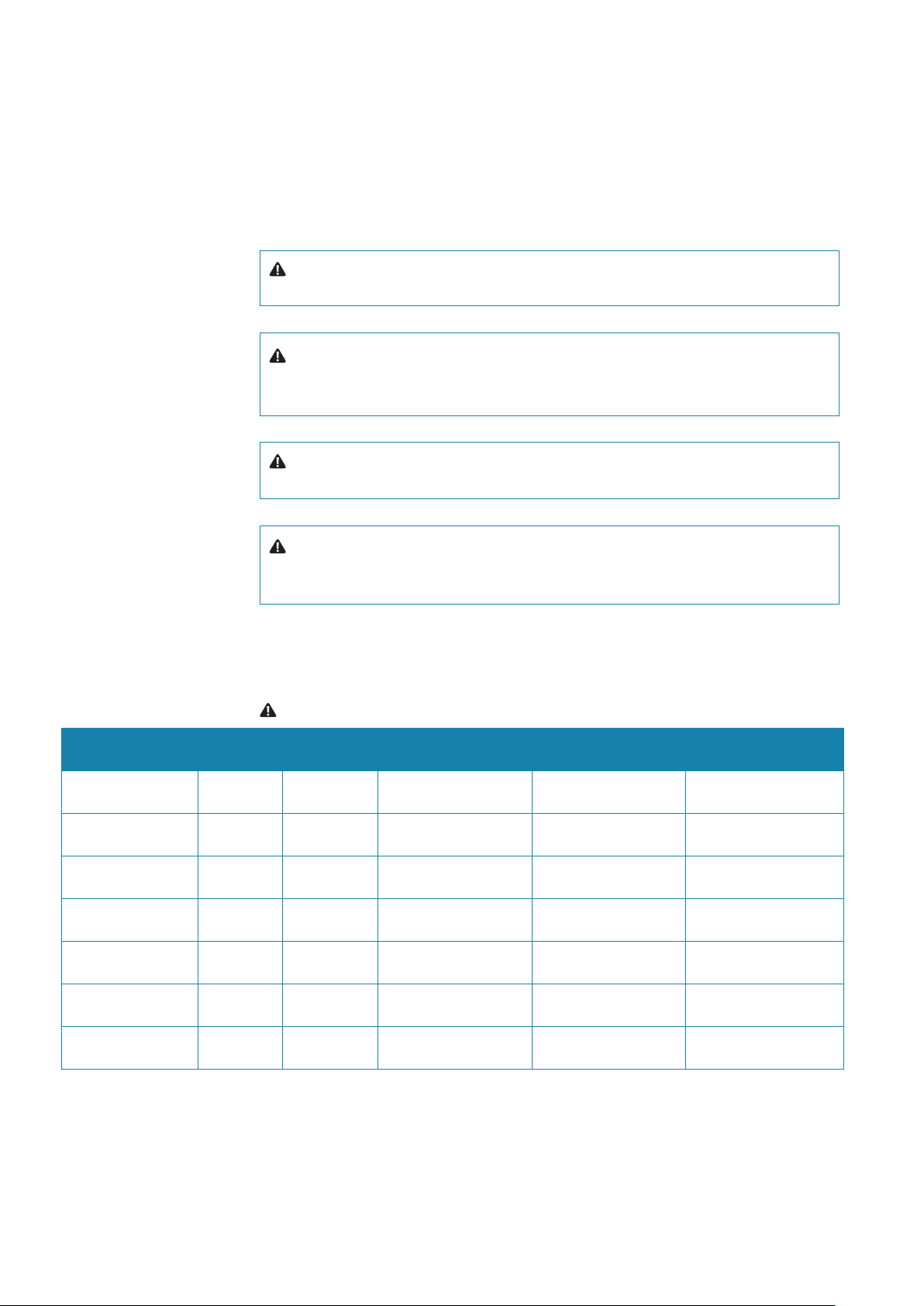
Warning: Microwave radiation levels
TXRX/
Pedestal
Antenna 100 W/m2 Power
density distance (m)
50 W/m2 Power density distance (m)
10 W/m2 Power density distance (m)
Argus 12U 6 ft. X-band 0.15 0.6
Argus 12U 9 ft X-band 0.5
Argus 12U 12 ft. X-band 0.35
Argus 25U 6 ft. X-band 0.1 0.2 1.3
Argus 25U 9 ft X-band 0.1 1
Argus 25U 12 ft. X-band 0.05 0.9
Argus 30U 12 ft. S-band 0.9
2 |
When a precaution, which relates specifically to a part of this manual is required, the information is given in the relevant part of the manual.
Warnings and Cautions precede applicable text.
| Argus Radar Operator Manual
Preface

High voltage
Radar equipment includes high voltage that can cause injury or loss of life. Danger exists only
when the units are opened and exposing internal circuits, as when servicing the equipment.
The ARGUS Radar has been carefully designed to protect personnel from possible injury from
high voltages.
Nevertheless, it is recommended that the Main Power Line shall always be OFF, as an added
protection when inspecting or servicing the equipment.
Although every effort has been made to eliminate danger to personnel, no responsibility is
accepted for any injury or loss of life suffered in connection with this equipment.
Safety switch
The Radar Unit is provided with a safety switch, which disables the antenna rotation during
maintenance and avoids high voltage damage. Always turn the safety switch off, whenever
the procedure advises to do so (for instance, before performing any maintenance or installation procedure). Ignoring safety switch operation may produce hazard of electrocution as well
as other severe injures.
Safety precautions
Purpose
The described safety precautions are applicable to the ARGUS Radar System. Depending
upon the material to be highlighted, the following notes are used in this manual.
¼ Note: An essential operating or maintenance procedure, condition or statement which must
be highlighted.
Whenever a precaution, relating specifically to a part of this manual is needed, the information is given in the relevant part of the manual. Warnings and Cautions precede applicable
text.
Safety operations
Main power line is always present on terminal board and fuses. During normal operation
(front cover closed), the unit can quickly be disconnected from the main power line, setting
the relevant circuit breaker, located on the electric switchboard, to OFF.
Safety summary
The following are general safety precautions not related to any specific procedure and
therefore do not appear elsewhere in this manual. These are recommended precautions that
personnel must understand and apply during most phases of operation and maintenance.
KEEP AWAY FROM LIVE CIRCUIT
Operating personnel must at all times observe all safety regulations.
Do not replace components or make adjustments inside the unit with the high voltage supply turned ON. Under certain conditions, dangerous potentials may exist when the power
breaker is in OFF position, also due to charges retained by capacitors. To avoid casualties,
always remove power and discharge a circuit to ground before touching it.
DO NOT SERVICE OR ADJUST ALONE
Under no circumstances should any person initiate servicing or adjusting the unit without the
presence of someone capable of helping.
RESUSCITATION
Personnel working with or near high voltage should be familiar with modern methods of
resuscitation. Such information may be obtained from the Bureau of Medicine and Surgery.
| Argus Radar Operator Manual
Preface
| 3
Warning information
The following warnings will appear in the text of the technical manuals, and are repeated here
for emphasis.
Warning: Use extreme care when working on the unit once the cover has been
opened. The magnetron assembly operates at voltages that may prove fatal.
Warning: Beware of high voltage capacitors. It is necessary to short-circuit their
leads before performing any maintenance action on them.
Warning: On the electric switchboard, set the power breaker dedicated to the
present equipment to OFF and hang up a placard reading: “work in progress - do
not switch on”.
Warning: Set main line breaker to OFF before replacing a fuse. The voltage in
fuses are under the level which may prove fatal.
X-Ray radiation
X-ray radiation may be generated by Transceiver units and care must be taken to avoid possible harmful effects when they are opened for maintenance. When power is on, care should
be taken not to approach closer than 1 foot (12 cm) from the unit unless front cover is in
place.
Radio frequency radiation
Harmful effects (particularly to the eyes) may be caused by exposure of any part of the human
body to radio frequency mean power densities in excess of 100 mW/cm2. This power density
is exceeded at a distance of 1 foot (12 cm) or less, from the 12 ft. X-Band aerial (when stationary).
The system is however designed to disable radiation when the antenna is not rotating.
The pedestals have also been predisposed for the installation of an external safety switch,
which can be mounted on, or near the platform. This switch removes power from the
Pedestal eliminating the possibility of accidental operation during servicing and also causes
disabling of transmission.
Whenever it is necessary to disconnect the waveguide system from a radar transmitter for
maintenance purpose, the transmitter output should, when practicable, be terminated in
a matched load. If this is not possible, care should be taken to avoid standing in front of an
open-ended waveguide from which power is being radiated.
¼ Note: NEVER look down on a waveguide from which power is being radiated.
4 |
| Argus Radar Operator Manual
Preface

Contents
1 Preface
9 General information
9 Introduction
10 Abbreviations
12 How to read the system version
12 Available versions
13 Physical description
13 Monitor unit
13 Control panel (keyboard)
13 Core unit
13 General functioning description
14 Target and data display
14 Video signal processing
14 Failure procedure
14 Watchdog function
15 Technical characteristics
19 Basic operation
19 Keyboard controls and indicators
21 Procedure to switch on the system
22 Monitor presentation (4:3 system)
25 Monitor presentation (wide screen)
26 General operating procedures
26 GUI Widgets description
26 Buttons
27 Labels
27 Shortcuts
27 Spin buttons
28 Switch buttons
28 List boxes
28 Combo boxes
28 Check buttons
28 Progress bars
29 The three function keys on the keyboard
32 Focusing function
32 Clicking in the ARGUS interface
32 Cursor shape
33 Menu window
33 Numeric and alphanumeric keyboards
34 The button’s label
34 Small menu-like icon
34 Tool icon
34 List of symbols
35 Own ship section
35 Gyro and speed
35 Gyro preset
36 Speed
37 Speed source selection
38 Log speed
38 Manual speed
38 Auto drift speed
39 EPFS speed
40 Course
40 Own ship geographic position
40 UTC or local time
40 Map name
41 Help line section
41 Operating mode section
41 Cursor section
41 Cursor
Contents |
Argus Radar System Operator Manual
| 5

41 Latitude and Longitude or ETA and TTG
42 Tracking section
42 Target tracking
42 Target track and AIS association mode
42 CCRP Position (Consistent Common Reference Point)
43 Parallel index menu
43 Main menu
43 Radar conguration
44 Personal settings
46 Video level equalization
49 Layout
50 Brilliance settings
50 Day color
50 Antares PCB info
51 Sharing
51 About Argus
52 ECDIS interface functions
54 Conning menu
57 Task window movement
57 Picture in picture
58 Additional PPI
59 Customizing radar control settings
61 Radar presentation and video processing
61 Presentation and visualization options section
61 Orientation and motion modes
61 Head Up
62 North Up
62 Course Up
62 Relative motion (RM)
62 True motion (TM)
62 P reset/TM reset
63 The row under PPI area
63 Range scale increase/decrease
63 Range rings on/o
63 PPI Centre/O centre
64 P reset/TM reset
64 Gnd Stab/Sea Stab
64 Heading line and PPI graphics on/o
64 Tune
65 Video processing section
65 Gain
66 Rain
67 Sea
69 Video preset
69 Interference rejection
70 Scan to Scan correlation
71 Mutual radar interference
71 Second trace echo
71 Sweep to Sweep correlation
71 Target enhancement
71 SART video presentation
74 RACON (Radar Beacon) video presentation
74 Racon technical characteristics
75 Video processing menu
76 Which preset is the right one?
77 TXRX interswitch menu (standard)
77 Master/Slave
77 Performance monitor on/o
78 Power normal/boost
79 TXRX data
79 Standard speed
79 TXRX interswitch menu (Conguration video combination)
80 Tracking and video processing operation in combination and 2
nd
PPI mode
6 |
Contents |
Argus Radar System Operator Manual

81 A or B combination
81 A and B combination
82 Sector combination
83 A and / or B combination
84 Measurement
84 Radar echo measurement
84 Measurement by means of range rings and bearing scale
84 Measurement by means of the cursor
84 Measurement by means of the ERBL 1 or 2
85 More target data measurement
86 Cursor section
86 Cursor
86 Latitude and Longitude or ETA and TTG
86 ERBL 1 and 2
87 Parallel indexes
89 Range rings
90 Tracking
90 General information
90 Radar target tracking facility
91 Tracking operation in 2
nd
PPI zone and under video combination mode
91 AIS (Automatic Identication System)
93 Tracking target symbols
99 Target overload
99 Radar target trails
100 Past positions
100 Vector time
101 True/Relative vector
101 Tracking menu
102 Anchor watch
102 Training target
102 Cancel ALL TGT
103 Minimum safety menu
103 Auto-Acquisition zone
103 Guard zones/Auto Acquisition zones
104 Trial manoeuvre
105 Manual trial manoeuvre
106 Automatic trial manoeuvre
109 AIS and radar target association
110 AIS On/O
110 AIS list
111 TT target list
111 AIS limit priority
111 AIS ltering
112 AIS options
112 Symbol
112 TT, AIS and navigation symbols
113 Route presentation and waypoint data
114 Predictor
114 Displaying target information
119 Maps
119 General information
120 Create a new map
123 Operating with a selected video map
123 Editing objects on the video map
125 Geographic map manual settings menu
126 Selection and movement with the trackball cursor
127 Selection and movement by means of the editable labels and buttons
128 Import and export of a map
Contents |
Argus Radar System Operator Manual
| 7

129 Alert and system failures
129 External bridge alert systems
129 Bridge Alert Management (BAM)
129 Bridge Navigational Watch Alarm Systems (BNWAS)
129 Type of alerts
129 Alert notications
130 Acknowledging alerts
131 The Alerts list
131 Audio On/O
131 Radar presentation failure
131 Alphabetic alarm listing
133 List of wrong operation messages
135 Operating modes fallback
136 Maintenance
137 ARGUS FMCW radar
137 General
138 Additional benets of FMCW radar
139 FMCW radar scanner specications
140 Overall dimension of FMCW radar
140 FMCW transceiver radar system installation and settings
140 Preliminary operations
140 First time installation
140 Activating the FMCW transceiver radar system
142 FMCW device conguration menu
143 Utilization of the FMCW transceiver radar system
143 Selection of the FMCW transceiver on additional PPI
144 Description of commands relative to the window of the FMCW radar transceivers
146 Limits
8 |
Contents |
Argus Radar System Operator Manual

1
General information
Introduction
The ARGUS Radar is a radar indicator with a presentation based on a raster scan principle.
The advantages of using the raster scan principles to produce a radar display are as follows:
• true daylight presentation
• continuous display of radar video
• high number of graphics that can be superimposed to the radar picture
• areas where all necessary navigational data can be presented at the same time.
The radar scans the horizon over a total of 360°, azimuth samples are converted and stored in
a memory, and then presented on a raster scan display. These conversion and memory logics
make the core (heart) of the indicator.
In order to have a display resolution similar or better as compared to a traditional radar
picture, very large memories are used. In addition, the display monitor is able to present
video data without loosing even the smallest information written into the memory. However,
various monitors with different resolutions can be connected to the ARGUS Radar System, so
depending on the choice of monitor, the graphic interface can be quite different from one
monitor to the next. The graphic layouts and widgets in this manual are examples only and
may therefore not appear exactly the same on the screen in your system.
In order to reduce the number of circuit boards (PCBs), a CPU performs multiple functions.
Therefore, the CPU has the total control of the system and gives the advantage to have very
sophisticated diagnostics and great flexibility.
Very large scale integrated micrologics are used.
A single card forms a complete sub-function and has very few connections to the rest of the
system.
The modular design in the base of the system and sub-units are easily replaced in case of
malfunction.
The ARGUS Radar performs the following operations:
• it receives the ship sensor’s data, which are:
GYRO - indicates the ship heading
LOG - indicates the ship speed
EPFS - indicates the ship position, speed and course
AIS - identifies the ships in the area
• it interfaces and receives signals from up to four transceivers (scanners), with relevant antenna,
and allows the operator to select the transceiver to be used for the presentation
• it processes the received signal in order to detect targets
• it processes the signal relevant to a target in order to obtain the target data: position, speed,
course, heading
• it automatically tracks a target in order to update the target data
• it shows the target position on the monitor.
General information |
Argus Radar System Operator Manual
| 9

Abbreviations
Navigation related information is very often presented using the standard terms or abbreviations. In the following table you will find the most common abbreviations and the ones used
in this manual.
Abbreviations
ACK Acknowledge
ACQ Acquire
ADJ Adjust
AIS Automatic Identification System
ALARM Alarm
ANCH Anchor Watch
ANT Antenna
AP Autopilot
ARPA Automatic Radar Plotting Aid
AUD Audible
AVAIL Available
AZ Acquisition Zone
AZI Azimuth Indicator
BCR Bow Crossing Range
BCT Bow Crossing Time
BKGND Background
BRG Bearing
BRILL Display Brilliance
BWW Bearing Waypoint To Waypoint
C UP Course Up
CCRP Conistence Common Reference Point
CENT Centre
CNCL Cancel
COG Course Over Ground
CONT Contrast
C PA Closest Point Of Approach
CPU Central Processing Unit
CRS Course
CTS Course To Steer
CURS Cursor
DAY/NT Day/Night
DECR Decrease
DEG Degrees
DEL Delete
DGPS Differential Gps
DISP Display
DIST Distance
DPTH Depth
DR Dead Reckoning
DSC Digital Selective Calling
DW Deep Water
EBL Electronic Bearing Line
Terminology
Abbreviations
ECDIS
ECS Electronic Chart System
EGNOS
ENCSOG Automatic Navigational Chart
EP Estimated Position
EPFS Electronic Position Fixing System
EPIRB Emergency Position Indicating Radio Beacon
EQUIP Equipment
ERBL Automatic Range And Bearing Line
E TA Estimated Time Of Arrival
ETD Estimated Time Of Departure
EZ Exclusion Zone
FK User Function Key
FMCW Frequency Modulated Continuous Wave
FWD Forward
GAS Grounding Avoidance System
GEOG Geographic
GLONASS Global Orbiting Navigation Satellite System
GMDSS Global Maritime Distress And Safety System
GND TRK Ground Track
GNDSTAB Ground Stabilised
GNSS Global Navigation Satellite System
GPS Global Positioning System
GYRO Gyro
GZ Guard Zone
H UP Head Up
HDG Heading
HL Heading Line
HR Hours
I/O Input/Output
IBS Integrated Bridge System
ID Identification
IN Input
INIT Initialisation
INS Integrated Navigation System
IR Interference Rejector
IRCS Integrated Radio Communication System
ISW Interswitch
Km Kilometre
KN Knots
Terminology
Electronic Chart Display And Information
System
European Geo-Stationary Navigational Overlay
System
10 |
General information |
Argus Radar System Operator Manual

Abbreviations
Terminology
LBL Label
LIM Limit
LOST TGT Lost Target
LP Long Pulse
m Metres
MAP Maps
MIN Minimum
MIN Minutes
MKR Marker
MOB Man Overboard
MP Medium Pulse
MSTR Master
N UP North Up
NAV Navigation
NC Normally Closed
N LT Not Less Than
NM Nautical Mile
NMT Not More Than
NUC Not Under Command
OFF CENT Off Centre
OFFTRK Off Track
OS Own Ship
OUT Output
PA D Predicted Area Of Danger
PAST
POSN
Past Positions
PCB Printed Circuit Board
PI Parallel Index Line
PL Pulse Length
PM Performance Monitor
POSN Position
PPC Predicted Point Of Collision
PRF Pulse Repetition Frequency
PWR Power
R BRG Relative Bearing
R CRS Relative Course
R VECT Relative Vector
RAD Radius
RCDS Raster Chart Display System
REF Echo Reference
REF SOG Echo Reference Speed
REL or R Relative
RM Relative Motion
RM (R) Relative Motion (Relative Trails)
RM (T ) Relative Motion ( True Trails)
RNC Raster Navigational Chart
Abbreviations
Terminology
RNG Range
ROT Rate Of Turn
RR Range Rings
RTE Route
RX Receiver
SAF CON Safety Contour
SAR Search And Rescue
SC/SC Scan To Scan
SDME Speed and Distance Measuring Equipment
SEL Select
SENC System Electronic Navigational Chart
SK Soft Key (each button of the trackball)
SNR Signal To Noise Ratio
SOG Speed Over The Ground
SP Short Pulse
SPD Speed
SRNC System Raster Navigational
STAB Stabilised
STBD Starboard
STBY Standby
STW Speed Through The Water
T BRG True Bearing
T CRS True Course
T SPD True Speed
T VECT True Vector
T C PA Time To Closest Point Of Approach
TGT Target
TM True Motion
TPR Transponder
TRIAL Trial Manoeuvre
TRIG Trigger Pulse
TRK Track
TRKG Tracking
TTG Time To Go
TWOL Time To Wheel Over Line
TX Transmit
TX Transmitter
TX/RX Transceiver
UPS Uninterruptible Power Supply
VRM Variable Range Marker
VTS Vessel Traffic Services
WOL Wheel Over Line
WOP Wheel Over Point
General information |
Argus Radar System Operator Manual
| 11
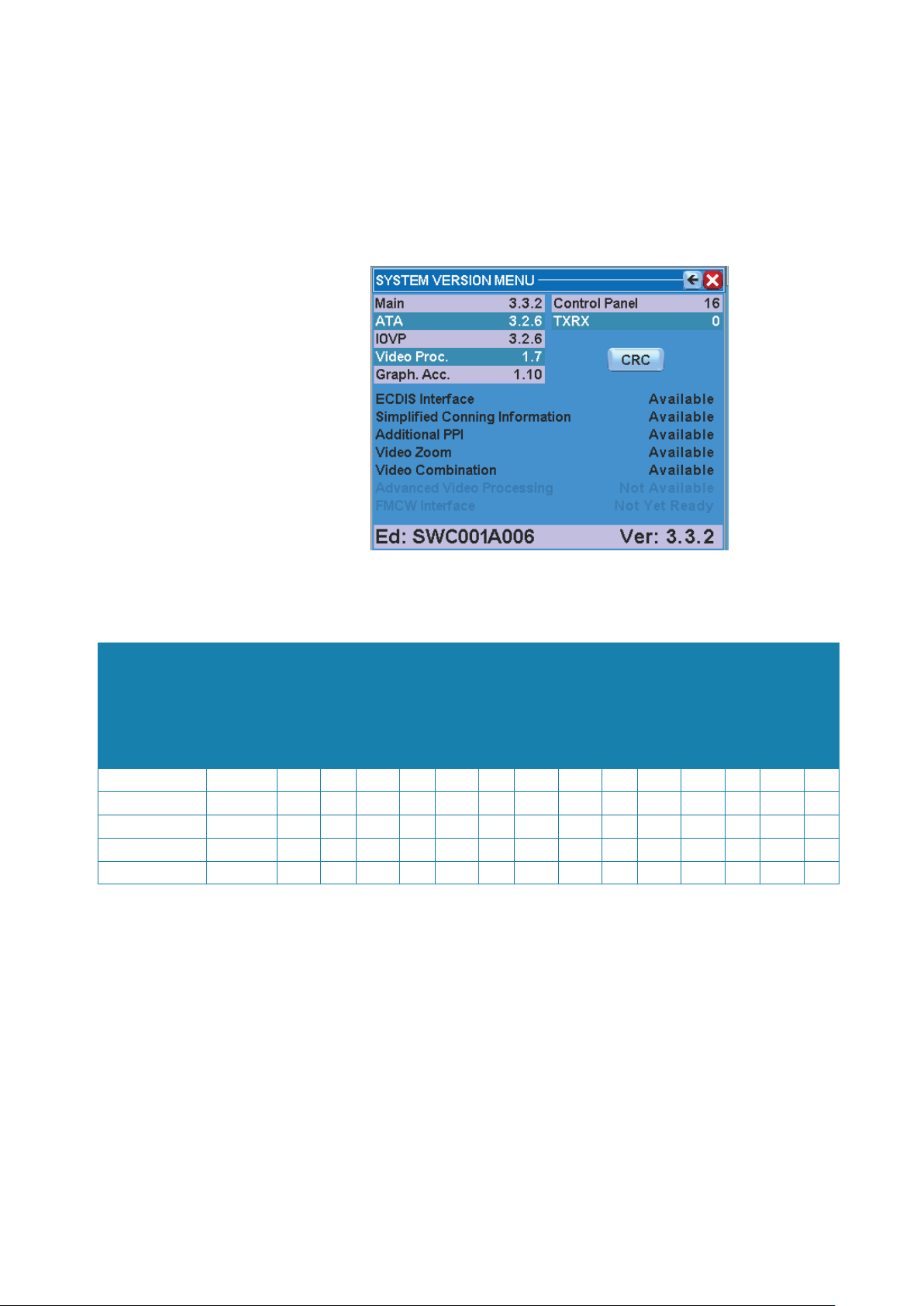
How to read the system version
The function of the System Version menu is to recognise the program and the version running within the system.
To display the System Version:
1. Open the menu by pressing the relevant button
2. Press the About Argus button.
This menu summarises all the programs running within the system.
Argus models
ARGUS P 340 WS >320 mm
ARGUS P 340 >320 mm
ARGUS P 250 >250 mm
ARGUS P 25O WS >250 mm
ARGUS P 180 WS >180 mm
Actual radar
Available versions
The system can be configured with different additional functions, according to the monitor
being used:
Trial
targets
Activated AIS
manoeuvres
• • • •
• • • •
• • • •
• • • •
Predictor
sharing
Network
Menu at both
•
sides
Additional PPI
targets
Tracked radar
additional PPI
FMCW Radar on
100 300 110
100 300 110
100 300 110
100 300 110
20 120 20
Total AIS targets
Video
picture
Combination
Zoom
Simplied
Conning
WIDE PPI
• • • • • •
• •
• •
• • • • • •
To better understand the different functions, see the following paragraphs:
Actual radar picture: See “PPI Centre/Off centre” on page 63.
Video Combination: See “A or B combination” on page 81.
Zoom: See “Zoom” on page 59.
Simplied Conning information: See “Conning menu” on page 54.
WIDE PPI: See “Monitor presentation (wide screen)” on page 25.
Menu at both sides: See “Layout” on page 49.
Additional PPI: See “Additional PPI” on page 58.
FMCW interface: See “Selection of the FMCW transceiver on additional PPI” on page 143.
Tracked radar targets: See “AIS and radar target association” on page 109.
Total AIS targets: See “AIS filtering” on page 111.
Activated AIS targets: See “Target overload” on page 99.
Trial manoeuvres: See under “Technical characteristics” on page 15.
Predictor: See “Predictor” on page 114.
ECDIS interface
12 |
General information |
Argus Radar System Operator Manual

Network sharing: See “Sharing” on page 51.
ECDIS interface: See “ECDIS interface functions” on page 52.
Physical description
The ARGUS Radar System consists of the following units:
• Monitor Unit on which the data, command buttons inside the SYSTEM DATA AREA, and the
echoes with relevant targets inside the PPI AREA are displayed.
• Core Unit in which the ARGUS electronic boards are mounted.
• Keyboard Unit on which the hardware of the Control Panel is mounted.
• Scanner Unit – not included. Refer to Simrad ARGUS Radar Scanner – Technical Manual.
Monitor unit
The Argus Monitor Unit represents the visual interface between the Operator and the Equipment. The equipment can be supplied with different types of Monitor Unit. Technical characteristics are located in the next paragraph.
Control panel (keyboard)
The Control Panel is the interface on which the operator can insert data, change the working
parameters and perform the operations necessary for the correct use of the equipment.
The Control Panel features light indicators, pushbuttons, rotating knobs and a trackball, which
controls the equipment. For more details, refer to Chapter 2.
The Control Panel is connected to the Core Unit by means of a cable with connector.
Core unit
The Core Unit consists of the following main parts protected in a dedicated cabinet::
• the Antares Assy
• the Alpha Board
• the optional Alpha Expansion Board
• the Power Supply mounted on the Alpha Board
• the Line Filter
• the Main Power Switch
For details, refer to Simrad ARGUS Radar Installation & Service manual.
The boards are made up of multi-layers printed circuits using VLSI components; programmable gate arrays and microprocessors are used to achieve a high package density, functional
reliability and low power consumption.
Auxiliary indicators (Light Emitting Diodes) are also located on the boards to allow easy
scheduled test, troubleshooting and maintenance actions.
The Line Filter is fixed to the left lateral panel of the Core Unit by means of nuts. The supply
voltage (115 VAC – 220 VAC 50/60 Hz) is applied through the Main Power Switch to the Alpha
Board.
The Alpha Board is fixed on the left side of the Core Unit by means of screws. The board is
the interface between the Argus monitor, auxiliary navigation equipment (GYRO, GPS, LOG,
AIS…) and the TXRXs (transceivers) connected. The interconnection allows commands to be
transmitted or received through BNC connectors and the Terminal connectors.
General functioning description
The Argus monitor receives the following signals from the connected transceiver(s):
• Video Signal
• Trigger
• Azimuth (AZ)
• Heading Line (HL)
• TXRX Data
The data is applied to the TXRX interface block of the Alpha Board that, upon command from
the Main Processor on the Antares Board, selects the transceiver to be used. The signals from
General information |
Argus Radar System Operator Manual
| 13

the selected transceiver represent the data on which the equipment operates.
The signal process mainly consists of two steps:
• the Video Signal Processing
• the Automatic Target Tracking.
The results of the signal processing are both visualised on the monitor and sent to the Automatic Target Tracking circuits.
Target and data display
The monitor presentation area is subdivided in a radar video presentation called PPI AREA
and a data table SYSTEM DATA AREA (for more details, refer to Chapter 2). The total area of
the screen is made up of a rectangle of pixels, depending on the size of the display. The video
signal and the graphic symbols (vectors, arcs, special symbols, bearing scale and segments)
are represented within the area of the PPI.
Video signal processing
This section receives the Video Signal from the transceiver and, after conversion into digital
form, processes it by removing:
• Sea Clutter
• Rain Clutter
• Interference.
The processed signal is sent to:
• the monitor for visualisation
• the Automatic Target Tracking circuits.
In the Video Signal Processing blocks, the digital signal is processed by means of complex
algorithms in order to recognise the presence of a target and, if the target is present, its shape
and the target coordinates.
The target coordinates and the target shape are sent, in digital form, to the Automatic Tracking Section of the equipment.
Failure procedure
This description does not describe failures that can occur during operation. If a failure occurs,
the operator must perform all relevant actions in order to remove the failure itself. When a
failure occurs, the fail condition is pointed out by:
• the red SYSTEM FAIL LED
• the acoustic alarm
• the Fail System Warning will be displayed in the General Purpose Section.
Watchdog function
Warning: The equipment’s operational software is monitorised by a hardware watch-
dog with a 3s timeout.
Non recoverable errors due to hardware faults are indicated by FAIL indication on the Control
Panel flashing at approximately 1 Hz.
Any type of failure caused by software or hardware, which stops the system for more than half
a second activates the System Failure relay on the Alpha PCB. This check doesn’t need software intervention, but is automatically controlled by the hardware. The Failure relay contact
is normally closed, so the function is active, also when the main line is absent or the power
supply has failed.
14 |
General information |
Argus Radar System Operator Manual
Technical characteristics
1 General description
The ARGUS Radar fully complies and exceeds IMO recommendations.
• IMO-Resolution A.278 (VIII), A.694 (17), A.823 (19), MSC 191 (79), MSC 192 (79)
• EN 62388 Ed.2.0, 2013
• EN 62288 Ed.2.0, 2014
• EN 60945 Ed.4.0, 2002 incl. Corr.1, 2008
• EN 61162-1 Ed.4.0, 2010
• EN 61162-2 Ed.1.0, 1999
The ARGUS Radar is composed of the scanner unit and three modules i.e. a desk-mounted Monitor Cabinet, Keyboard and
Core Unit. Thanks to the modular design, it can be assembled to form a stand-alone display cabinet or may be flushmounted into a mechanical bridge console. The standard basic configuration always includes an electronic, built-in Interswitch for
dual radar installation.
The above flexibility makes the ARGUS Radar the optimum solution for a dual radar system on new constructions and retrofit installations.
2 Display unit Actual radar picture
(mm)
Monitor size: 16/19” WS > 180 mm 1366 x 768 1 CAT3
Monitor size: 24” WS > 250 mm 1920 x 1080 1 CAT2/CAT2H
Monitor size: 19” > 250 mm 1280 x 1024 1 CAT2/CAT2H
Monitor size: 23” > 320 mm 1600 x 1200 1 CAT1/CAT1H
Monitor size: 26” WS > 320 mm 1920 x 1200 1 CAT1/CAT1H
Monitor size: 27” WS > 320 mm 1920 x 1080 1 CAT1/CAT1H
Performance for categories of ship/craft for Solas V
Description CAT3 CAT2 CAT1
Minimum operational display area 180 mm 250 mm 320 mm
Minimum Display Area 195 x 195 mm 270 x 270 mm 340 x 340 mm
Auto Acquisition of Targets YES YES YES
Acquired Radar Targets Capacity 20 100 100
Active AIS Targets Capacity 30 110 110
Sleeping AIS Targets Capacity 120 300 300
Trial Manoeuvre YES YES YES
3 Technical specications
Video processing • Digital processing on: 8 bit (256 levels)
• Manual /Automatic Sea anti-clutter and rain anti-clutter
• Sweep to sweep (Interference Rejection), scan to scan video correlation for residual sea
clutter removal, target enhancement
• Scan to scan correlation for echo trails. True and relative trails calculated simultane-
ously in every presentation mode
• Trails are maintained between changes in range scale and PPI position
Presentation modes Day/night modes
- Relative motion (RM) Head up, Course up and North up
- True motion ( TM) Course up and North up
O-centering Up to 50 % of range scale in use
Range scales 0.125, 0.25, 0.5, 0.75, 1.5, 3, 6, 12, 24, 48, 96
Range rings 0.025, 0.05, 0.1, 0.25, 0.75, 0.5, 1, 2, 4, 8, 16
Range resolution 3 m on 0.75 NM range scale
Resolution
(pixels)
Suggested viewing
distance (m)
Category of ship/
craft
General information |
Argus Radar System Operator Manual
| 15

3 Technical specications
VRM Dual VRM from 0 to 96 NM with digital readout
VRM resolution 0.01 NM
VRM accuracy 1% of range scale in use
Azimuth resolution 0.1°
EBL Dual EBL with independent 0-360° true or relative digital readout
EBL resolution 0.1°
Trackball Polar and Geographic coordinates continuously displayed
Diagnostics On-line diagnostic built-in
Radar target facilities:
Acquisition Manual or automatic up to 100 or 20 targets (depending on the category), up to 24 NM
Tracking Automatic up to 100 or 20 targets (depending on the category), up to 24 NM
Auto acquisition/
Guard Zones
One auto acquisition zone stabilized on Ownship heading and size/shape configurable.
Four sectors with fixed width of 0.5 NM configurable as auto acquisition or guard zone
AIS facilities:
Presentation Up to 300 or 120 targets (depending on the category), in sleeping accepted with selectable
priority (nearest range, most dangerous). Presentation filters according to AIS class, range,
CPA, TCPA, speed
Acquisition Manual or automatic activation of up to 100 targets CAT1/2 or 20 targets CAT3 plus manual
selection through a table ordered in ship name and distance
Safe Checking All AIS targets in sleeping or activated state
Auto acquisition/
Same zones described in Radar Target facilities
Guard Zones
Trial manoeuvres:
Trial course For ARPA and AIS targets. Manually adjustable from 0° to 360° or automatically computed
within 135° with reference to the present course
Trial speed Adjustable from 0° to 50 Knots
Trial ROT Adjustable from 1° to 60°/min.
Trial time Adjustable with 1 minute increments
Mapping: Operator compiled maps up to 120 segments plus symbols and text strings with selectable
colors and line styles
Map Stabilization Relative, True (Dead Reckoning) or geographic
Map storage By Name, on a built-in non volatile memory. Transferable via USB Memory stick
Map adjustment Position and orientation
Graphic functions: True or relative time adjustable vectors
Target identification number, trackball marker and true marks. AIS identification number,
ship names or call signs
Time adjustable past position plots
Four independent parallel index lines
Waypoints and Route from EPFS
Ownship shape and activated AIS target shape on lower range scales
Additional features:
Zoom Enlarges a selected area over the main PPI
Picture in Picture (CCTV) Opens a window inside which is an area of the ship for monitoring; e.g. the hold or car deck
of a ship. (Number of video input channels according to monitor specifications)
16 |
General information |
Argus Radar System Operator Manual

3 Technical specications
Simplified conning information
Graphic display of sensors, e.g.:
• Wind sensor
• Steering Gear
• Heading sensor
• CCTV Input
• Echo sounder
• SDME sensor
Additional PPI Additional PPI with the same functions as the main PPI, including the possibility to interact
with different TXRXs at the same time
ECDIS interface Function for complete integration with an ECDIS system connected via LAN
Video Combination Possibility to select two radar sources and the possibility to view the two sources at the
same time in a single image. The automatic Tracking uses the two sources to track targets,
even across the blind sectors of the radar antennas
Data readout:
ARPA Target data Range/bearing, speed/course, CPA/TCPA and Latitude/Longitude
AIS Target data Ship Name, MMSI, Call Sign, Range/bearing, speed/course, CPA/TCPA and Latitude/Longi-
tude, Type, Status, Destination, ETA, ship size, AIS class
Ownship data Heading, Speed/Course water or ground stabilized Geographic position and UTC time
System setting: Safe Minimum CPA & TCPA, vector/past positions / trial / trials time
Alarms: Acoustic and visual warning for: Dangerous Target, Target in Guard Zone, Lost Target, Sys-
tem Failure and external interface sensors (EPFS and AIS)
Other features: Anchor-watch, echo reference speed (not for AIS enabled systems), EPFS speed
Built-in, electronic dual interswitch facility plus additional expansion, up to four transceivers.
Coaxial cable only connection (SXI mode) to TXRX
Inputs:
Gyro Heading Analog: synchro or stepper. Digital Fast NMEA (IEC 61162-2)
Speed Log Analog: PIT or two axis log. Digital: NMEA (IEC 61162-1)
EPFS Serial Interface NMEA (IEC 61162-1)
AIS Serial Interface NMEA (IEC 61162-1)
External Alarm Interface Serial Interface NMEA (IEC 61162-1) – RAACK sentence
Outputs:
Serial Interface NMEA 0183 (IEC 61162-1)
RATTM - RAOSD – RARSD – RAALR – RATLB – RATTD sentences
Dead Man Alarm, Power Fail, Danger Target relay outputs configurable as NC or NO
Other interfaces: Double Ethernet port 10/100 with a full set of TCP/IP protocols. System redundancy for LAN
connection failure
Four USB 2.0 port
Environmental features:
Operating temperature -15°C / 55°C (IEC 60945 protected equipment)
Storage temperature -25°C / 70°C (IEC 60945 protected equipment)
Relative humidity Up to 95% at 40° (IEC 60945 protected equipment)
Water proofness IP66
Vibrations As per IEC60945
Power consumption: 500 W max (depending of monitor and wind load on TXRX)
Power Supply: 220/115 VAC 50/60 Hz
Dimensions: Core unit only: Width 46 cm, height 35 cm, depth 15 cm
Weight:
Keyboard 2 kg
Core unit: 9 kg
General information |
Argus Radar System Operator Manual
| 17
3 Technical specications
Type approval: IEC 60945 (General Requirements)
IEC 62388 (Radar Performance)
IEC 61162-1/2 (NMEA interface)
Warning: Highest mast position is good for long range detection, but it heavily affects
the detection in sea clutter. For optimal detection in sea clutter, suggested antenna height
from sea level is around 20 m. Usually the contradictory specifications are solved with
installation of more than one antenna, e.g. one at 30 m for long range detection and one
at 20 m for optimal detection of low intensity echoes in sea clutter. THe S-band transceiver
is always the optimal choice for reducing rain clutter reflections and increase long range
detection. Longer antennas for X-band are less susceptible to rain and sea clutter.
Warning: According to IMO standard, a ground speed sensor is required to be con-
nected to the Argus console. Only electronic positioning systems (EPFS) approved in accordance whit the requirement of the IMO in resolution msc.112(73) shall be connected to
the radar console.
It is allowed to use an electronic position fixing system (EPFS) approved in accordance with
the requirements of the IMO in resolution msc.112(73) or an alternative two dimensional
ground stabilising SDME in compliance with IMO resolution msc.96(72).
Warning: Only electronic positioning systems (EPFS) approved in accordance with the
requirements of the IMO in resolution msc.112(73) shall be connected to the radar console.
Warning: The radar unit is provided with a safety switch, which disable the antenna
movement during maintenance operations and avoids high voltage damage. Always turn
the safety switch off, whenever advised in this manual (for instance, before performing any
maintenance or installation procedures). Ignoring safety switch operation may produce
hazard of electrocution as well as other severe injures.
18 |
General information |
Argus Radar System Operator Manual
2
Basic operation
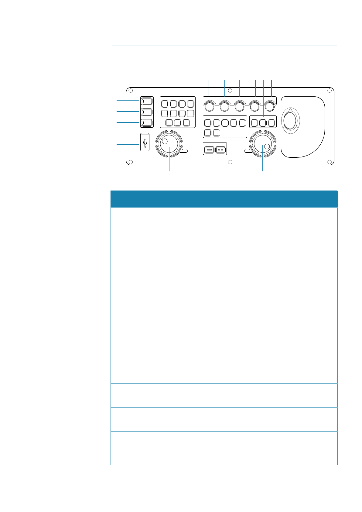
Keyboard controls and indicators
5 7 8 12 9 10 14 11 15
1
2
3
POWER
TX ON
FAIL
SYSTEM
CHART RADAR OTHERCONN
SHOW
MOB EVENT AUDIO
LAYER
FNCT 1 FNCT 2 FNCT 3
4
EBL
BRILL GAIN SEA
DISPLAY TRACKING
TM /
COURSEUPHEADUPNORTHUPPRES
RM
OFF
CENTRE
CENTRE
RANGE
RESET
RAIN TUNE
ACQ
VRM
SEL
CANCEL
6 13 6
Control or
Ref.
indicator
Description and function
1 POWER This pushbutton with green LED indicator is used to switch between
Sleep and On conditions. When the system is in Sleep condition it
appears to be Off, but the electronic is still on, waiting for the real On
condition request. In order to switch on the monitor, and the control
panel, the operator has to press the POWER button, and holding it
pressed for more than 5 seconds. An audible beep will sound and the
green LED next to the pushbutton will change to high brilliance.
In “On” condition, by pressing the POWER button again, the monitor,
and the control panel will be switched off again and another beep
will sound and the green LED will return to low brilliance, bringing the
system into a Sleep mode (to shut down the system completely, the
main power switch of the core unit must be set to position 0).
2 TX ON This pushbutton is used to switch the system between Standby and
TX ON. In Standby the display does not request the TXRX to transmit,
but it is possible to get some information from the system, depending
on the type of TXRX connected. In TX ON the radar (if Master) radiates and the antenna turns. This is the normal working condition (the
switching “Standby to TX ON” and “TX ON to Standby” are executed at
the release of the pushbutton).
3 FAIL This indicator is normally Off. A red-colored LED will be switched on
when a system failure occurs (this is an indicator, not a button).
4 USB port USB type 2.0. Main purpose is to simplify file sharing and software
upgrading.
5 SYSTEM
user
functions
Momentary pushbuttons used to access the function or to execute
one of the three programmable functions (FNCT 1, 2, 3) as described
in “The three function keys on the keyboard” on page 29.
6 EBL/VRM Use the rotary knob to set the EBL/VRM 1 or 2 alternatively. The EBL/
VRM data are displayed in the related windows. For further details,
refer to “Measurement by means of the ERBL 1 or 2” on page 84.
7 BRILL Monitor and keyboard dimmer. Push to toggle Day/Night.
8 GAIN GAIN control. Push to toggle Manual/Auto modes. The optimum set-
ting is when the receiver background noise is hardly visible. For further
details, refer to “Gain” on page 65.
Basic operation |
Argus Radar Operator Manual
| 19

Control or
Ref.
indicator
Description and function
9 SEA Anti-Sea Clutter by reducing the gain at minimum range gradually
returning to normal. Push to toggle Manual/Auto modes. The gain
varies with the distance according to a predetermined curve and in an
amount proportional to the setting. When the potentiometer is turned
fully counter clockwise, the gain is uniform over the entire screen.
10 RAIN Anti-Rain Clutter. Push to toggle Manual/Auto modes.
Large target masses will show only the immediate shoreline, thus,
permitting prominent targets on land to appear. Rain or snow clutter
can be reduced by the use of the potentiometer, and covered target
revealed. For more details, refer to “Rain” on page 66.
11 TUNE
Push for 2 seconds to toggle between Manual/Auto modes. If manual,
keep it pressed to change the tuning. The tuning may be checked by
means of the numeric indicator on the screen, or directly by observing
a target echo. In the last case, the echo level should be slightly above
the noise level (not saturated). The tuning meter indication is displayed
on long pulse only. For more details, refer to “Tune” on page 64.
12 DISPLAY:
TM/RM Toggles True Motion and Relative Motion modes.
COURSE UP Momentary pushbutton used to select a stabilised Course Up presen-
tation. Press again in Course Up mode to enter a new course reference.
HEAD UP Momentary pushbutton used to select Head Up presentation (referred
to Heading Line).
NORTH UP Momentary pushbutton used to select North Up presentation
(referred to Gyro North). When the PPI is in True Motion mode the
presentation is automatically selected. For more details, refer to “North
Up” on page 62.
PRESS RESET Momentary pushbutton used to reset the position of own ship 180°
against the course.
OFF CENTRE Momentary pushbutton used to set the off-centered presentation
on the point under the cursor of the trackball (if the cursor is placed
inside the PPI).
For more details, refer to “PPI Centre/Off centre” on page 63.
CENTRE Momentary pushbutton used to set the PPI centered presentation.
Not active in True Motion presentation.
13 RANGE Two momentary pushbuttons used to select one of the 10 different
range scales, expressed in NM, and the relevant range rings for PPI
presentation.
With the + pushbutton it is possible to increase the range scale while
with the - pushbutton it is possible to decrease it. For further information refer to “Range scale increase/decrease” on page 63.
14 TRACKING:
ACQ(UIRE) Momentary pushbutton used to acquire a radar target or to activate
an AIS target.
SEL(ECT) Momentary pushbutton used to display alphanumeric information
related to the selected radar target or AIS.
CANCEL Momentary pushbutton used to delete a tracked radar target or to
deactivate an AIS target.
15 TRACKBALL Positioning input device. Use the trackball to move the cursor on the
PPI (displayed as a cross) and on the system data area (Menus area,
displayed as a black arrow, except for the progress bars in which it is
possible to change the value, where it’s displayed as a double horizontal thin arrow).
20 |
Basic operation |
Argus Radar Operator Manual
Procedure to switch on the system
Switching on the main power switch placed on the core unit, the system will boot and the
Standby window will appear. Pushing the POWER button the system will switch between
Standby and Sleep mode. When the system is in Sleep mode it appears to be powered off,
but the electronics are still on, waiting for the actual Power On mode request. In order to
switch on the monitor and the keyboard, the operator has to press the POWER button, and
holding it for more than 3 seconds. An audible beep will sound and the green LED next to the
pushbutton will change to high brilliance.
In Power On mode, by pressing this pushbutton again (for more than 3 seconds), the monitor and the keyboard are switched off again, another beep will sound and the green LED will
change back to low brilliance; the system is now in Sleep mode (to shut down the system
completely you need to switch off the main power switch of the core unit.
After switching on the system, the Standby window will be shown on the monitor and the
brilliance is automatically set to the lowest level in night colors. This feature is important in
case of switching on during the night to avoid a strong flash into the eyes of the operator. For
daylight operation, click on the centre mouse key or press the BRILL button to obtain the day
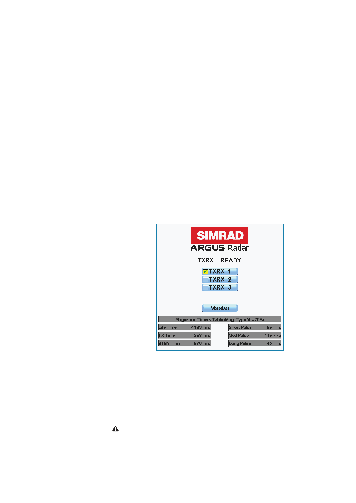
highlighted colors palette. The Standby window below provides informative data, such as:
• TXRX Status (Standby, Short, Medium or Long Pulse, warm-up countdown, etc.)
• Possible selection of Transceivers (with only one connected, no selection is possible)
• Operation mode at the next TX ON (master or slave)
• Magnetron and System Life Times (available only for TXRX version 54 or higher).
When the system is in Standby (Standby window visible in the centre of the screen and TX ON
yellow LED off) the operator is allowed to switch on the RF transmission, using the TX ON button. In Standby the radar display does not require the TXRX to transmit, but the transmission
could be on due to the control by another display or the TXRX could also be in Local mode
in transmission (for more details regarding the Local/Remote mode refer to the transceiver
technical manual). In TX ON mode, the radar antenna (if Master) radiates and turns. This is the
normal working condition (Standby to TX ON and TX ON to Standby switching are executed
at the release of the pushbutton).
Warning: In TX ON condition, pressing the TX ON button the system will return to
Standby.
Basic operation |
Argus Radar Operator Manual
| 21
Monitor presentation (4:3 system)
The monitor function is to visualise all necessary information to carry out the scheduled navigation and show information related to targets, own ship, settings and measurements, etc.
According to the procedure described in the previous paragraph, clicking the TX ON button
will turn on the yellow LED and set the scanner in transmit mode. When transmitting, the following window will be displayed on the screen.
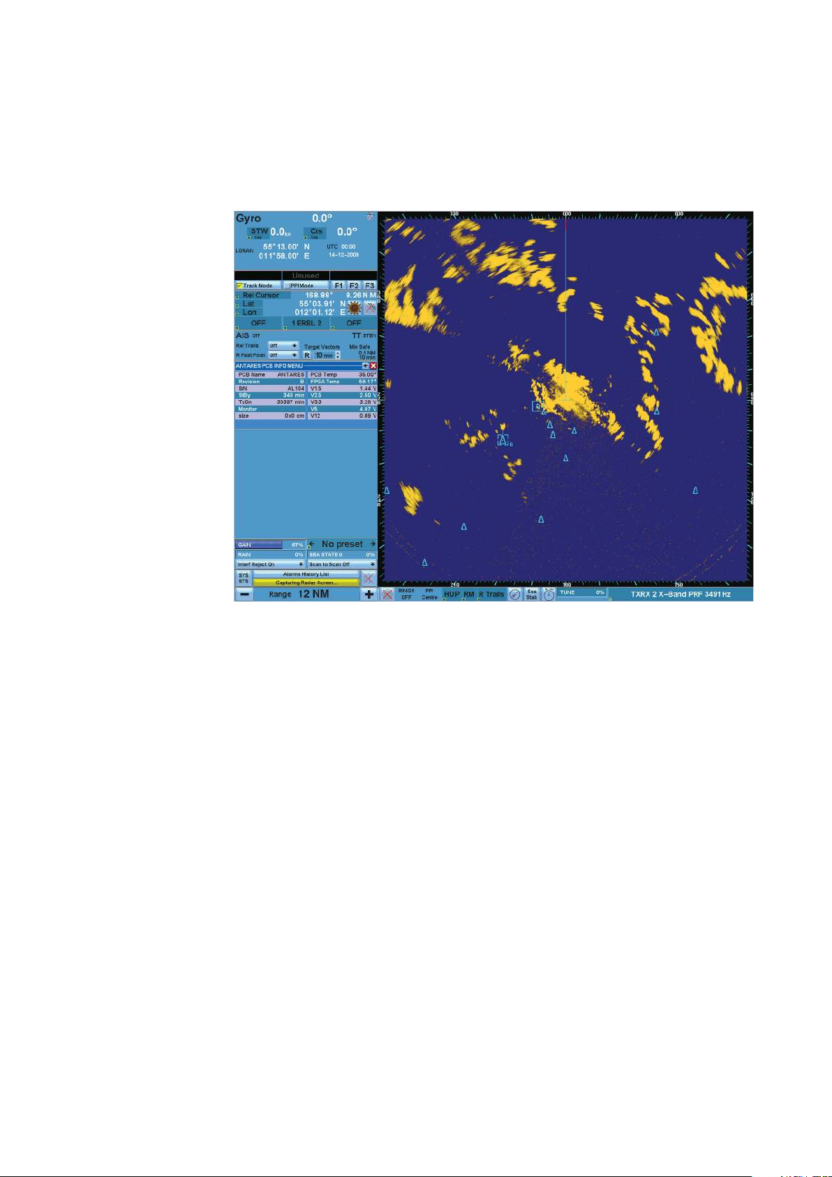
Monitor Display - General view
The window displayed can be divided into the following two main areas:
• PPI area in which the radar video is displayed. In this area all the tracking and navigation op-
erations can be performed.
• SYSTEM DATA area, which features all the menus for the operator to control the system, to set
all the data required by the system and to perform all the radar target /AIS operations. The
SYSTEM data area is organised in the following 9 sections - see next page.
22 |
Basic operation |
Argus Radar Operator Manual

1) Own ship
2) Help line
3) Operating mode
4) Cursor
5) Tracking
6) Main menu control
7) Displaying information
System data area sections
Basic operation |
Argus Radar Operator Manual
8) Video processing
9) Alerts/System status/Failure
10) Presentation modes
| 23

System data area
Ref. Sections Function
1 Own ship In this section all parameters regarding own ship are indicated:
• AIS operating mode (ON/OFF, if connected)
• Heading
• Speed and course
• Own ship geographic position
• UTC or Local time
• Map name (if displayed)
• Number of tracked targets or AIS with target overflow identification
• AIS input priority, display filtering, source data during target association.
2 Help line This line with three columns indicate the various options for each mouse button according to
the operating mode (Tracked target, PPI, Map editing).
3 Operating mode Selecting one of the two modes, the operator can select operating in Tracked target or PPI
mode. Changing the operating mode, will consequently change the suggestions in the help
line and the functions of the three function buttons on the keyboard.
4 Cursor In this section all parameters regarding the cursor are displayed i.e. Cross cursor in:
• Range and bearing, true or relative
• Geographic position.
5 Tracking In this section all parameters regarding AIS and targets are shown:
• Number of tracked targets or AIS with target overflow identification
• AIS input priority, Display filtering, Source data during target association.
6 Main menu control By pressing the main menu, a dropdown menu with submenus will be displayed. Refer to
“Main menu” on page 43 for the explanation of these submenus.
7 Displaying
information
In this section (normally empty), the information, data and measurements according to the
operator actions e.g. the menu and the target data are displayed.
8 Video processing This section includes the signal processing menu. The signal processing menu includes: GAIN,
RAIN, SEA, Scan to Scan Correlation, Sweep to Sweep Correlation.
9 Alerts/System
status/Failure
This section provides the Alerts list, the System status and the Failures.
• System status: it is displayed the status of the following unit: Trigger, Antenna, Heading line,
Gyro, Log, Radar External Interface (REI), Keyboard, TX/RX, Auto Tracking Aid (ATA), Video
process.
10 Presentation modes This section of the System data area monitor includes the buttons and shortcuts for:
• Visualisation: In the Orientation and Presentation modes section, the operator can select
the visualisation mode of the monitor display
• TX/RX Control status: Master/Slave, Power, PRF
• Presentation reset : The function of this button is to reset Own Ship position in the PPI
(True or Relative)
• Range Scale: selected Rings On, the operator, by means of the two buttons + and – will
increase or decrease the range scale
• System warnings and Wrong orders.
24 |
Warning: The true data (bearing, data, vector, etc) are always related to north and rela-
tive to heading.
Basic operation |
Argus Radar Operator Manual
Monitor presentation (wide screen)
This type of configuration has the same basic characteristics as the 4:3 monitor, but with the
availability of a larger area in which to view the different sensors.
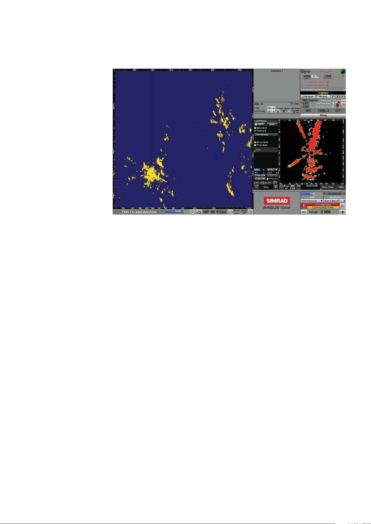
Monitor display - Wide screen
The window displayed can be divided into the following two main areas:
PPI area in which the video radar is displayed. In this area, upon command of the operator, all
the tracking and navigation operations can be performed.
SYSTEM data area, the same functions as the 4:3 system monitor, but with a larger area for
extended functions, like graphics sensor presentation.
Basic operation |
Argus Radar Operator Manual
| 25
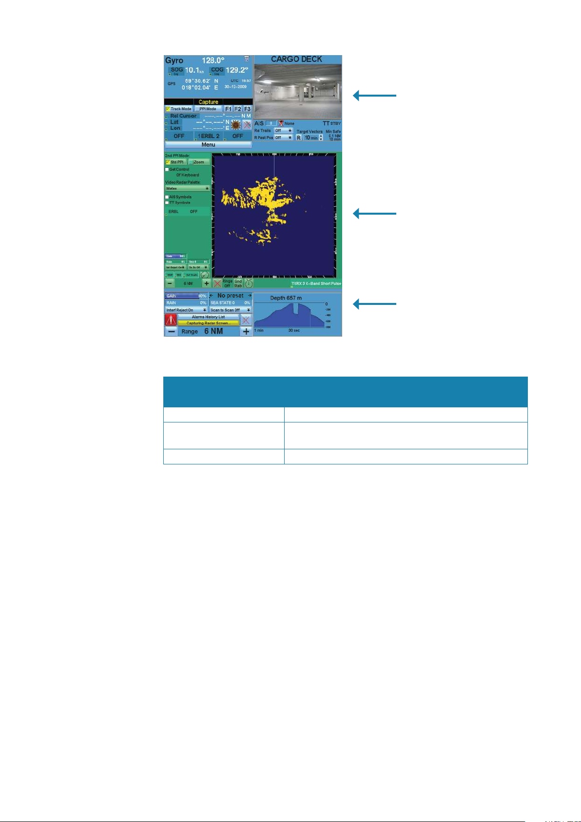
System data area sections
Area 1
Sensor information
2nd PPI mode
Main menu and sensor area
information
Area 3
Sensor information
System data area
Sections Function
Area 1 Sensor information In this area, it is possible to view up to two sensors
2nd PPI mode. Main menu
and sensor area information
Area 3 Sensor information In this area, it is possible to view up to two sensors
In this area, it is possible to view up to four sensors or it can
be used exclusively to view the second PPI
General operating procedures
In order to properly operate the ARGUS radar, it is necessary to know some basic information
regarding the GUI (Graphic User Interface), the menu structure, how to reach each function
and what information is available in the ARGUS radar display.
A general description of the GUI, which describes each section of the System data area is
provided in “Own ship section” on page 35.
GUI Widgets description
The GUI of the ARGUS radar display is composed by objects called widgets, described in the
following sub-paragraphs.
Buttons
Pressing the buttons, will consequently perform an action. The buttons can be sub-divided
into the button types:
• Menu buttons, which open a window with another menu. They have a square symbol on the
right, similar to a small menu window and they don’t change their caption
• Bi-stable buttons, which just change a parameter (i.e. ON/OFF) and consequently change
their caption
• Mono-stable buttons, which perform an action, not changing their caption (i.e. range +)
• List buttons, which open a List box or a Combo box under them. They have a down-oriented
arrow symbol on the right and they change their caption according to the section of the list.
26 |
Basic operation |
Argus Radar Operator Manual
Bi-stable button (On and O) Menu button List button
The different type of buttons look very similar and when pressing them, the operator can see
that the button has been pressed.
Button style when pressed Button style when focusing (cursor pointing)
Almost all of the buttons activate their action when they are released after being pressing,
so the operator has the possibility to move the mouse pointer away and not execute their
action even if he already pressed them. The buttons have a focusing function (for more details
regarding the focusing refer to “Focusing function” on page 32).
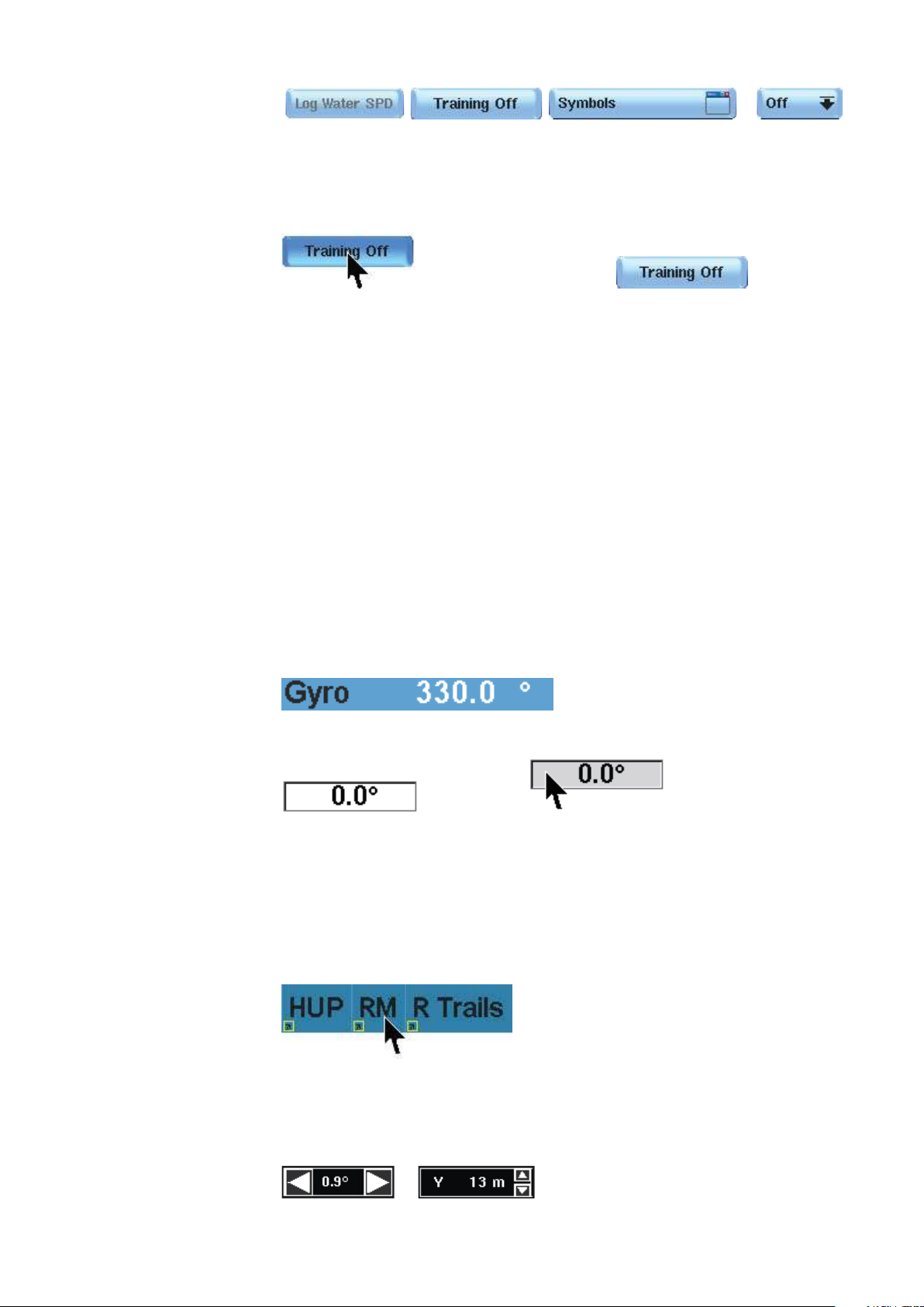
Labels
Normally the Labels are just indications, placed where important context information is
described, but some of them are editable, and the operator can change their caption or the
value indicated in them. The editable labels can easily be distinguished as they have a frame
and the focusing function (for more details regarding the focusing refer to “The three function
keys on the keyboard” on page 29).
The Normal labels are just indications; they don’t have any frame or focusing function. The
data that they contain can be in two different colors depending on the selected palette and
if the data is static or dynamic. For example: with the day blue palette, around the top side of
the System data area, “Gyro” is written with a dark color, as it’s static (it’s always “Gyro”). Next to
it there is the gyro value, which is in a bright color, as it is dynamic.
When the numerical field shows a ----.— the data is invalid or missing.
Normal labels (Static and Dynamic)
Editable label (with frame) Focusing on Editable label
Shortcuts
The shortcuts are essentially a shorter way to modify the status of various radar aspects, for
example switching On/Off the ERBL or changing the Orientation mode without having to
enter the main menu and thereafter the respective menu. Passing over the shortcuts with the
mouse pointer, the possible options will appear in the Help line.
Spin buttons
The Spin buttons are similar to labels, but with some important differences. It is possible to
change the displayed value by passing with the mouse pointer over the two horizontal or
vertical arrows.
Basic operation |
Argus Radar Operator Manual
| 27
It is also possible to modify the value by passing with the mouse pointer over the value itself.
The possible choices will appear in the Help line, in this case:
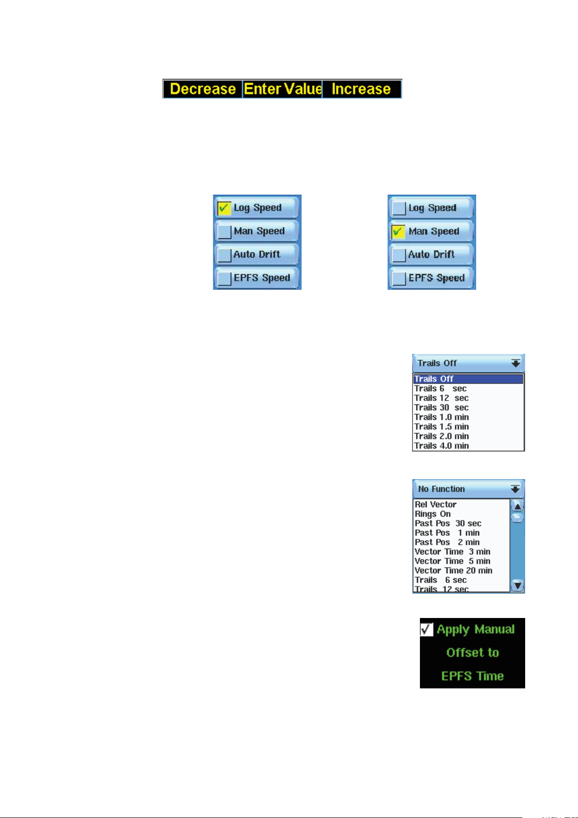
Switch buttons
These widgets look very similar to the previously described buttons, but their behaviour is
very different:
Normally they form a group in which only one is selected. All the others are automatically deselected. The green “√” inside a yellow square indicates the selected Switch button.
Switch button no. 1 selected, going to select no. 2 ..... Switch button no. 2 just selected.
The Switch buttons have the focusing function (for more details regarding the focusing, refer
to “The three function keys on the keyboard” on page 29).
List boxes
The List boxes are lists of items which are displayed when
pressing the buttons with the down-oriented arrow on the
right (List buttons, see “Buttons” on page 26). Having selected an item, the list is automatically closed and the caption
of the button memorizes the selected item.
When the list is open, clicking outside the List box or on the
button, the list will automatically close with no effect.
Combo boxes
The Combo boxes look very similar to the List boxes. They are
lists of items displayed by pressing the button with the same
kind of symbol, but they can contain a lot of items and the
quantity of them can not be fixed. On the right side of the lists
they have a column with an upper-oriented arrow at the top, a
down-oriented arrow at the bottom and a slide bar in the
middle, so the operator can scroll the list up and down to
visualize all the items.
28 |
Check buttons
The Check buttons are just a label which meaning can be activated or deactivated according to the “√” in the white square on
the left. The function indicated in the label is deactivated if the
white square does not have a “√”.
Progress bars
The Progress bars are rectangular or rotary bars showing a value by their blue filling and a
numerical indication of the current value.
Some of them can accept an input by the operator: when the cursor over a progress bar is
represented by a left-right oriented arrow, it means that the operator can increment or decrement the value of the bar using left/right SK; otherwise the bars just indicate their value and
Basic operation |
Argus Radar Operator Manual
 Loading...