

Simrad AP70,AP80 Operation Manual
AP70/AP80
Operator Manual
ENGLISH


Preface
Disclaimer
As Navico is continuously improving this product, we retain the right to make changes to the
product at any time which may not be refl ected in this version of the manual. Please contact
your nearest distributor if you require any further assistance.
It is the owner’s sole responsibility to install and use the equipment in a manner that will
not cause accidents, personal injury or property damage. The user of this product is solely
responsible for observing safe boating practices.
NAVICO HOLDING AS AND ITS SUBSIDIARIES, BRANCHES AND AFFILIATES DISCLAIM ALL
LIABILITY FOR ANY USE OF THIS PRODUCT IN A WAY THAT MAY CAUSE ACCIDENTS, DAMAGE
OR THAT MAY VIOLATE THE LAW.
Governing Language: This statement, any instruction manuals, user guides and other
information relating to the product (Documentation) may be translated to, or has been
translated from, another language (Translation). In the event of any confl ict between any
Translation of the Documentation, the English language version of the Documentation will be
the offi cial version of the Documentation.
This manual represents the product as at the time of printing. Navico Holding AS and its
subsidiaries, branches and affi liates reserve the right to make changes to specifi cations
without notice.
Compliance
The AP70 and AP80 systems complies with the following regulations:
• Wheelmark directive 2002/84 EC (HCS and HSC)
• CE (2004-108 EC EMC Directive) - AP70 systems when used with an AC70 computer
• C - Tick
Note: AP70 systems are not wheelmark approved when used with an AC70 computer.
For more information please refer to our websites:
pro.simrad-yachting.com and www.simrad-yachting.com.
The Wheelmark
The AP70 and AP80 system are produced and tested in accordance with the European Marine
Equipment Directive 96/98. This means that the systems comply with the highest level of
tests for nonmilitary marine electronic navigation equipment existing today.
The Marine Equipment Directive 96/98/EC (MED), as amended by 98/95/EC for ships fl ying
EU or EFTA fl ags, applies to all new ships, to existing ships not previously carrying such
equipment, and to ships having their equipment replaced.
This means that all system components covered by annex A1 must be type-approved
accordingly and must carry the Wheelmark, which is a symbol of conformity with the Marine
Equipment Directive.
While the autopilot system may be installed on vessels not needing to comply with the
Marine Equipment Directive, those requiring compliance must have one Control unit set-up
as a “master unit” in order for the installation to be approved.
Navico has no responsibility for the incorrect installation or use of the autopilot, so it
is essential for the person in charge of the installation to be familiar with the relevant
requirements as well as with the contents of the manuals, which covers correct installation
and use.
Copyright
Copyright © 2012 Navico Holding AS.
Preface | AP70/80 Operator Manual
| 1

Warranty
The warranty card is supplied as a separate document.
In case of any queries, refer to the our websites:
pro.simrad-yachting.com and www.simrad-yachting.com.
About this manual
This manual is a reference guide for operating the Simrad AP70 and AP80 Autopilot Systems.
The manual will be continuously updated to match new software releases. The latest available
manual version can be downloaded from our web sites.
Important text that requires special attention from the reader is emphasized as follows:
Note: Used to draw the reader’s attention to a comment or some important information.
Warning: Used when it is necessary to warn personnel that they
should proceed carefully to prevent risk of injury and/or damage to
equipment/personnel.
2 |
Preface | AP70/80 Operator Manual

Contents
5 Introduction
5 The front panel and keys
6 The screen
8 Operational mode overview
9 Basic operation
9 Safe operation with the autopilot
9 Using an external system selector to control autopilot operation
9 External follow-up override
10 Turning the autopilot system on/off
10 The menus
10 Dialog boxes
10 Display illumination
11 Ta k i n g command
11 Selecting autopilot modes
12 Switching from automatic mode to hand steering
12 Selecting work profi les
12 Acknowledging a message
12 Working with thrusters
14 Delegation of control in multiple station systems
14 Steerin g stations
14 Open systems
15 Master systems
18 The operational modes
18 M ode overview
18 External s ystem selector
19 Hand steering
20 AUTO modes
23 U-turn pattern steering
26 Controlling steering performance in automatic and navigational modes
27 Simulator mode
28 Work pro le setup
28 The Normal profi le
28 Creating new profi les
32 Edit a profi le
32 Importing and exporting work profi les (AP80 only)
34 The alarm system
34 Message types
34 Alarm indication
35 Acknowledging a message
35 The alarm dialogs
36 Setting the alarm and warning limits
36 Fallback and failures during automatic steering
37 List of possible alarms and corrective actions
Contents | AP70/AP80 Operator Manual
| 3

42 Maintenance
42 Preventive maintenance
42 Simple maintenance procedures
42 Restoring factory default settings
43 Software upgrades
43 Backing up your system data
43 File management
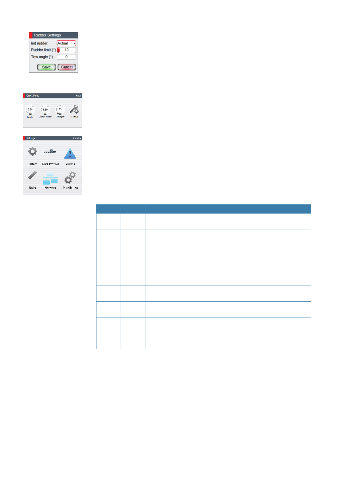
44 Menu overview
44 The Quick menus
45 The settings dialog and submenus
47 System con guration
47 General
47 The settings dialog and submenus
47 Turning on for the fi rst time
48 Network settings
52 Installation settings
58 Seatrials
60 Tuning the autopilot for optimum steering performance
62 List of display abbreviations
4 |
Contents | AP70/AP80 Operator Manual
1
Introduction
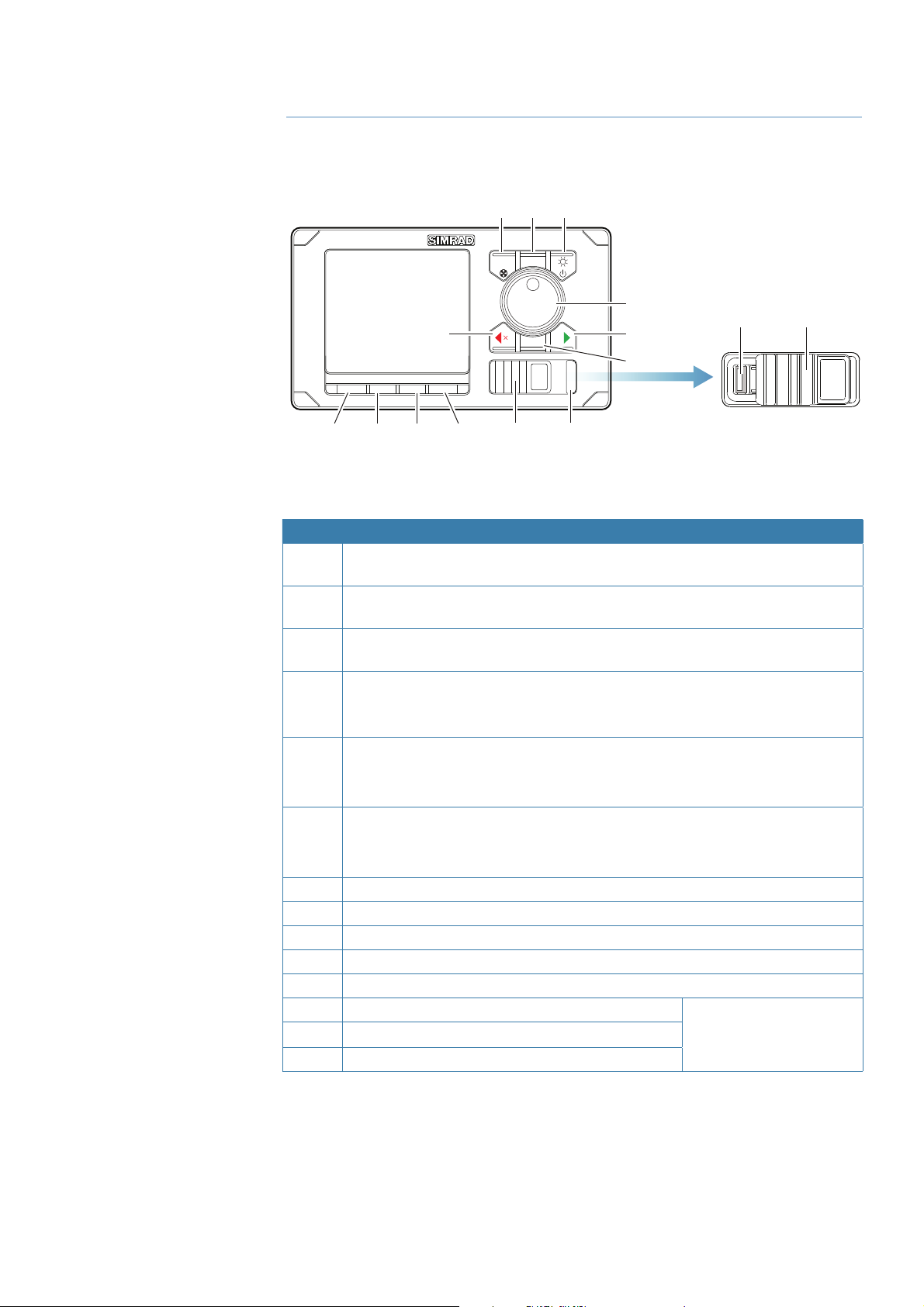
The front panel and keys
123
MENUCMD
5
TURN
4
3
6
14* 12*
7
STBY AUTO NAV WORK
91011
8
* Available on AP80 control units only.
No. Key/Description
1 CMD/THRUSTER. A short press takes/requests command. A long press (3
seconds) activates/deactivates available thrusters
2 MENU. A short press displays the active steering mode’s quick menu. A second
click displays the Settings menu
3 POWER/LIGHT. A short press displays the Light dialog. A long press (3 seconds)
turns the unit ON/OFF
4 ROTARY KNOB (Course wheel). Rotated for selecting menu item and adjusting
value, pressed to confi rm a selection/entry.
For mode specifi c operation, refer to “The operational modes” on page 17
5 PORT (Cancel). Exits menu/returns to previous menu level.
Activates NFU steering when in Standby mode.
Changes set heading, set course and track off set to port.
6 STBD (Confi rm). Confi rms menu selection/enters next menu level.
Activates NFU when in Standby mode.
Changes set heading, set course and track off set to starboard.
7 TURN. Displays the Turn dialog
8 STBY. Turns the autopilot to Standby mode
9 AUTO. Activates Auto and NoDrift mode
10 NAV (AP70) / TRACK (AP80). Activates Nav steering mode
11 WORK. Used for selecting work profi le
12 USB port door
13 ALARM. Displays the Alarm listing dialog
14 USB connector
12*
ALARM
13*
AP80 control units only
ALARM
Introduction | AP70/AP80 Operator Manual
| 5
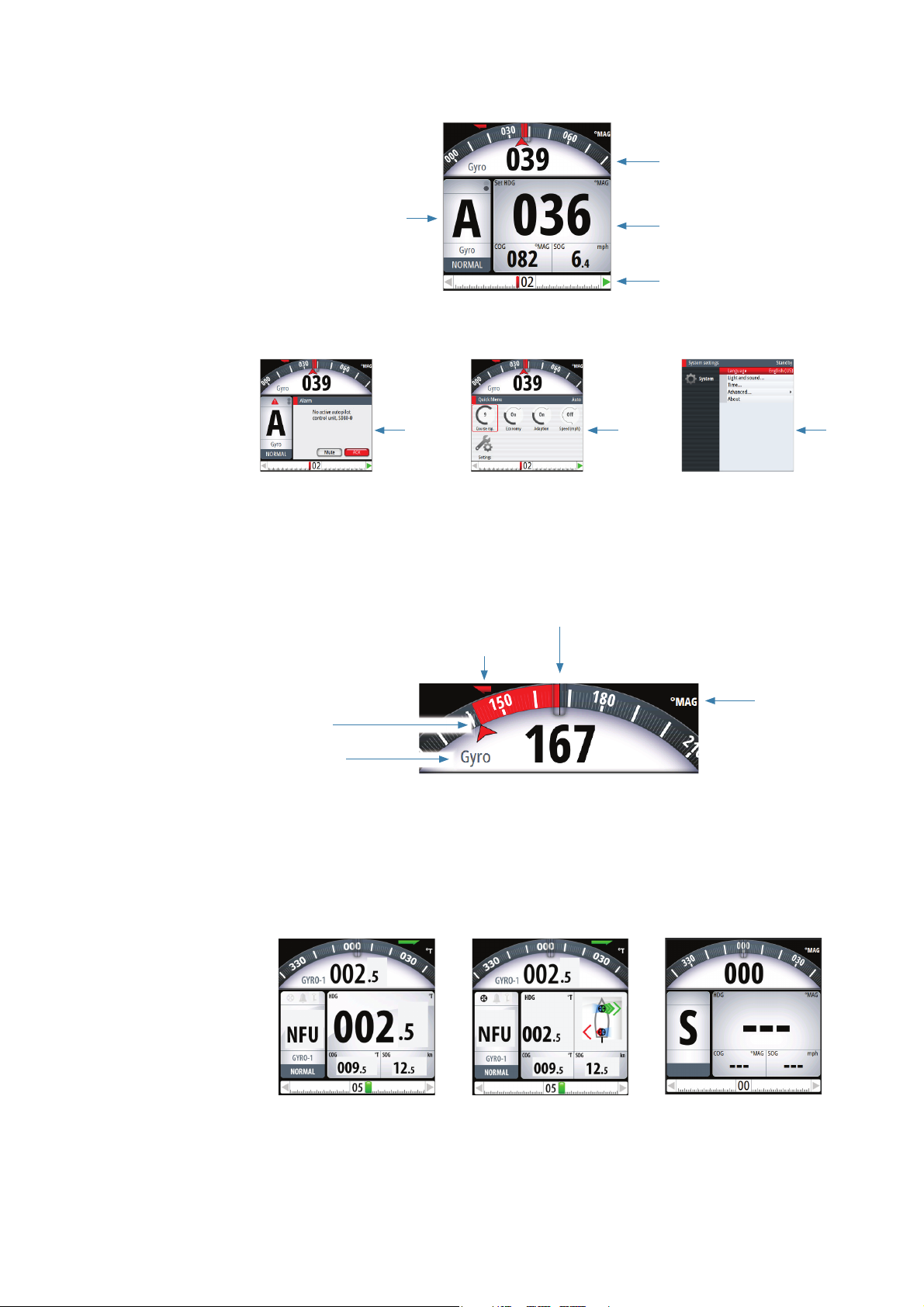
The screen
1
4
2
3
567
1 Heading repeater
Analog and digital heading readout. Digital readout is shown with one decimal if true
heading.
In automatic modes the diff erence between current and set heading is red for port, green for
starboard deviation.
Current heading
Rate indicator
Heading repeater
(
T
Set heading
Steering reference
2 Mode Info panel
The panel contains mode specifi c content and varies with the operational mode. See “The
operational modes” on page 17 onwards for more details.
If a thruster is available and active, the mode info panel will be split to show thruster
information.
If sensor input is missing, the numbers will be replaced with hyphens.
No active trusters Active thrusters No sensor input
rue or Magnetic)
unit
6 |
Introduction | AP70/AP80 Operator Manual
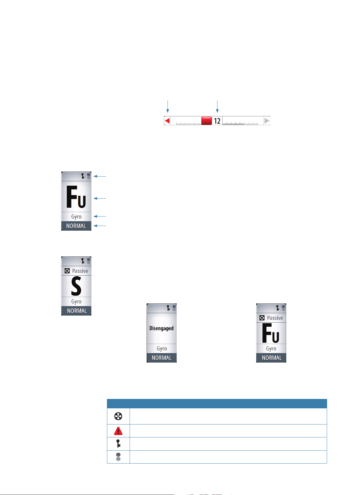
3 Rudder bar
Rudder position indicator with digital and analog readout.
The digital readout shows 1 bar per 1° rudder angle up to 40°. Rudder angle above 40° will
have a non-linear indication in the outer left/right part of the bar.
Direction indicators are turning red (port) and green (starboard) when rudder movement is
commanded. The direction arrows are only shown when rudder feedback is available.
C
ommanded
rudder dir
ection
* Showing commanded rudder angle in systems with analog steering without rudder
feedback.
4 Status panel
Status icons
The following mode abbreviations are used:
Rudder angle *
S: Standby
Mode indication
Steering reference
Active work pro le
If the autopilot is operated from another unit, this is shown in the mode indication fi eld.
If the autopilot is controlled by an external system selector or by an external follow-up, the
mode indication will be replaced as below.
FU: Follow Up
NFU: Non Follow Up
A: Auto heading
ND: No Drift
N: Nav
Autopilot disengaged by external system selector Rudder controlled by external follow-up
Available status icons are shown below. Only active icons will be visible.
Icon Description
Icon available if one or more thrusters are installed. The icon will be shaded when
the trusters are unavailable for steering
Active alarm message. Red icon for alarms, yellow for warnings
Control unit locked
Screen alive indication - white and black “balls” fade-swap color
Introduction | AP70/AP80 Operator Manual
| 7
5 Dialogs
Used for user input or for presenting information to the user.
A dialog may be presented in full-screen or as an overlay. Depending on type of information
or entry, diff erent keys are used to confi rm, cancel and close the dialog.
A dialog can always be closed by selecting the Close/Cancel dialog key, or by pressing the
PORT key.
6 Quick menus
Mode dependant menu, displayed by pressing the MENU key. The Quick menus contain the
most common used settings for the active mode. The menu varies with the autopilot mode
and also with the way the autopilot is operated.
7 Settings menus
Used for installation and system setup. The menus are activated from the quick menu, or by
pressing the MENU key twice.
Operational mode overview
The autopilot has several steering modes. Number of modes and features within the mode
depend on available input as shown below.
The modes are described in “The operational modes” on page 17.
MODE FEATURE DESCRIPTION
STBY
NFU
FU
AUTO Auto compass mode. Keeps the vessel on set heading
Heading
capture
Turn
(Pattern)
NoDrift
Heading
capture
NAV
Standby mode used when manually steering at the helm. Compass
and rudder angle will be shown on the display
Non-Follow-Up steering where the rudder movement is controlled by
using the red (port) or green (starboard) keys, or by another NFU unit
Follow-up steering where the rudder angle is set by the rotary knob or
by another FU unit
Aborts the turn and uses the instantaneous compass reading as set
heading
Moves the vessel automatically in pre-defi ned turn steering patterns
Automatic steering, keeping the vessel on a straight bearing line by
compensating for drift
Aborts the turn and uses the instantaneous compass reading as set
heading
Navigation steering. The vessel is steered to a specifi c waypoint
location, or through a route set on a chart plotter
8 |
Introduction | AP70/AP80 Operator Manual
2
Basic operation
Safe operation with the autopilot
Warning: An autopilot is a useful navigational aid, but DOES NOT
under any circumstances replace a human navigator.
Do not use automatic steering when:
• In heavy traffi c areas or in narrow waters
• In poor visibility or extreme sea conditions
• When in areas where use of autopilot is prohibited by law
When using an autopilot:
• Do not leave the helm unattended
• Do not place any magnetic material or equipment near the magnetic or fl uxgate compass
used in the autopilot system
• Verify the course and position of the vessel at regular intervals
• Always switch to Standby mode, and reduce speed in suffi cient time to avoid hazardous
situations
Using an external system selector to control autopilot
operation
IMO resolution MSC64 and other regulations require that an external switch is used for
changing over from manual to automatic steering.
Manual steering
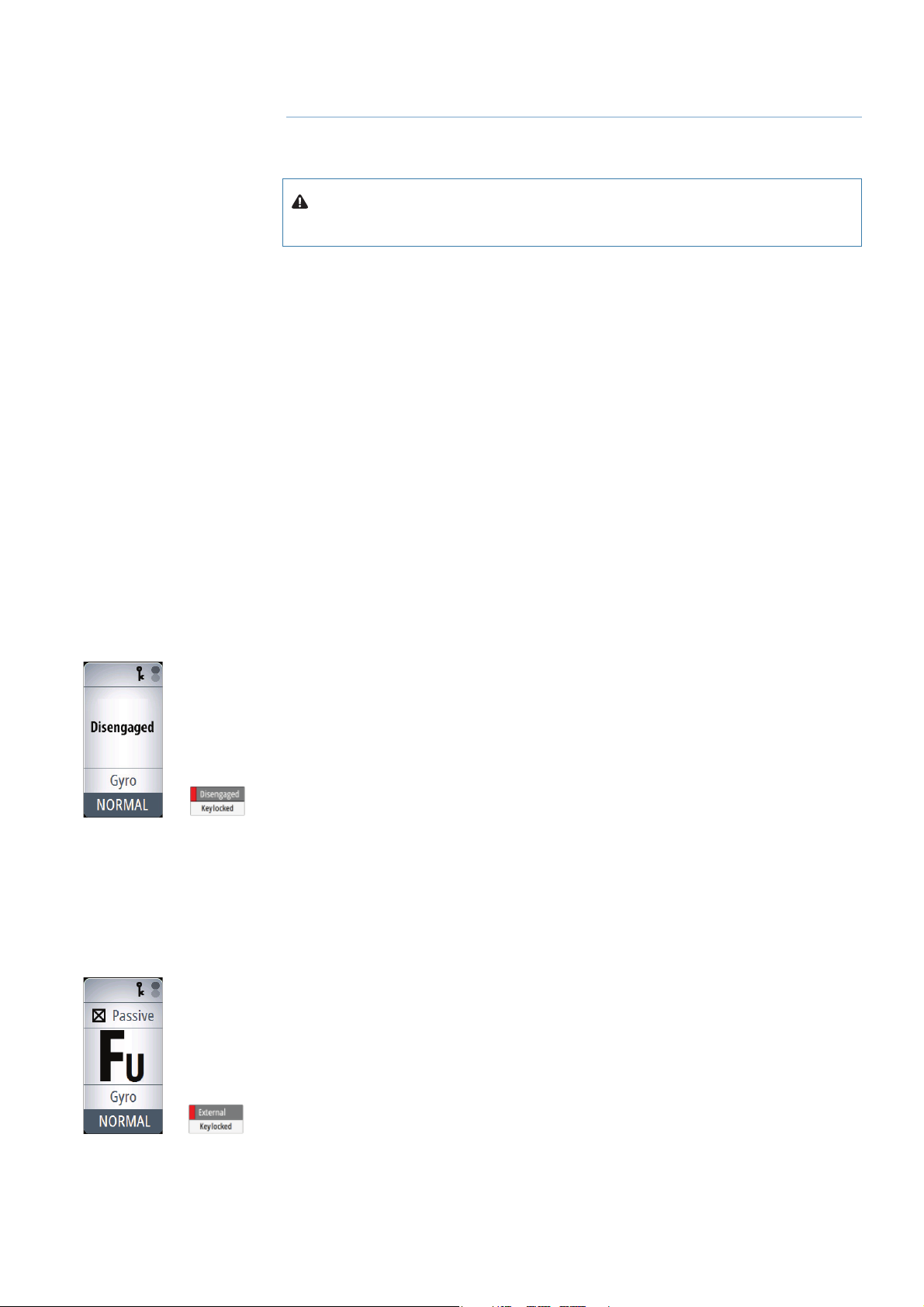
When an external system selector is set to manual steering, the autopilot will be disengaged.
The control unit will display information as in Standby mode. It is not possible to change to
FU, NFU or to any automatic mode. The menus can however be used, alarms acknowledged
and illumination adjusted.
When the autopilot is disengaged by an external switch, this will be indicated in the mode
display.
When a mode key is pressed, a dialog will show that the autopilot system is disengaged.
Autopilot operation
When the external selector is set to automatic steering, the autopilot will go directly to AUTO
heading mode with present heading as set reference. The autopilot can then be used in all
operational modes.
External follow-up override
On some autopilot computers you can connect a switch for allowing an external follow-up to
override autopilot control of the rudder. Refer the autopilot installation manual for connection
details.
When external follow-up override is selected, it is not possible to use any mode keys. The
menus can however be used, alarms acknowledged and illumination adjusted.
When the rudder is controlled by an external FU, this will be indicated in the mode display.
If you press a mode key, external control is indicated in the display.
Basic operation | AP70/AP80 Operator Manual
| 9
Turning the autopilot system on/o
You turn ON the autopilot system on by a short press on the POWER key when this is red
light colored.
The system is turned OFF (Sleep mode) by pressing and holding the POWER key on an active
control unit. During the shut-down procedure the system will automatically go to Standby
mode before it is turned off . If the POWER key is released before shut-down is completed,
the power off is cancelled.
Note: The POWER key will remain lit on units that are turned OFF. Note: To stop the system
from drawing current a separate breaker should be installed.
The menus
You display a menu by pressing the MENU key.
• Use the rotary knob to select a menu item, then press the rotary knob or the STBD key to
confi rm your selection
• Toggle on /off a check box by pressing the rotary knob or the STBD key
• Activate a slide bar by pressing the rotary knob or the STBD key, then select the value by
turning the rotary knob. Confi rm your selection by pressing the rotary knob or the STBD key
• Expand a Drop-down listing by pressing the rotary knob or the STBD key, then select the
item by turning the rotary knob. Confi rm your selection by pressing the rotary knob or the
STBD key
• Press the PORT key to return to previous menu level. Repeat pressing the PORT key to exit
the menus.
Check box Slide bar Drop-down listing
Dialog boxes
You select entry fi elds and keys in a dialog box by using the rotary knob. You can only enter
information when a fi eld is selected and highlighted.
You exit a dialog and cancel your entries by selecting the Cancel key in the dialog, or by
pressing the PORT key.
You confi rm your entries and close the dialog by selecting the OK key in the dialog, or by
pressing the STBD key.
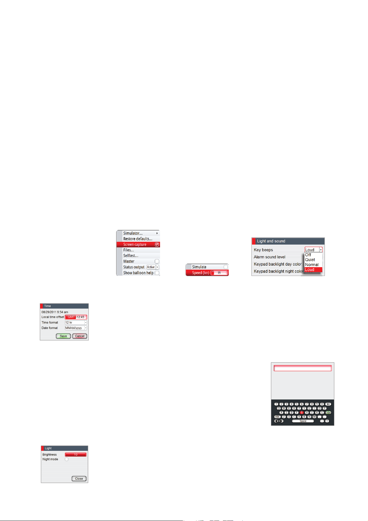
An alphanumeric keyboard will automatically be displayed when
required for entering user information in dialogs.
1. Select characters by turning the rotary knob
2. Confi rm your entry by pressing the rotary knob
3. Complete your entry by pressing the Enter key on the virtual
keyboard
Display illumination
Light adjustment
A single press on the POWER key will display the light adjustment dialog. The brightness
level is adjusted by the rotary knob.
Repeated presses on the POWER key will toggle between preset brightness levels (10 - 6 - 3-
1).
10 |
Basic operation | AP70/AP80 Operator Manual
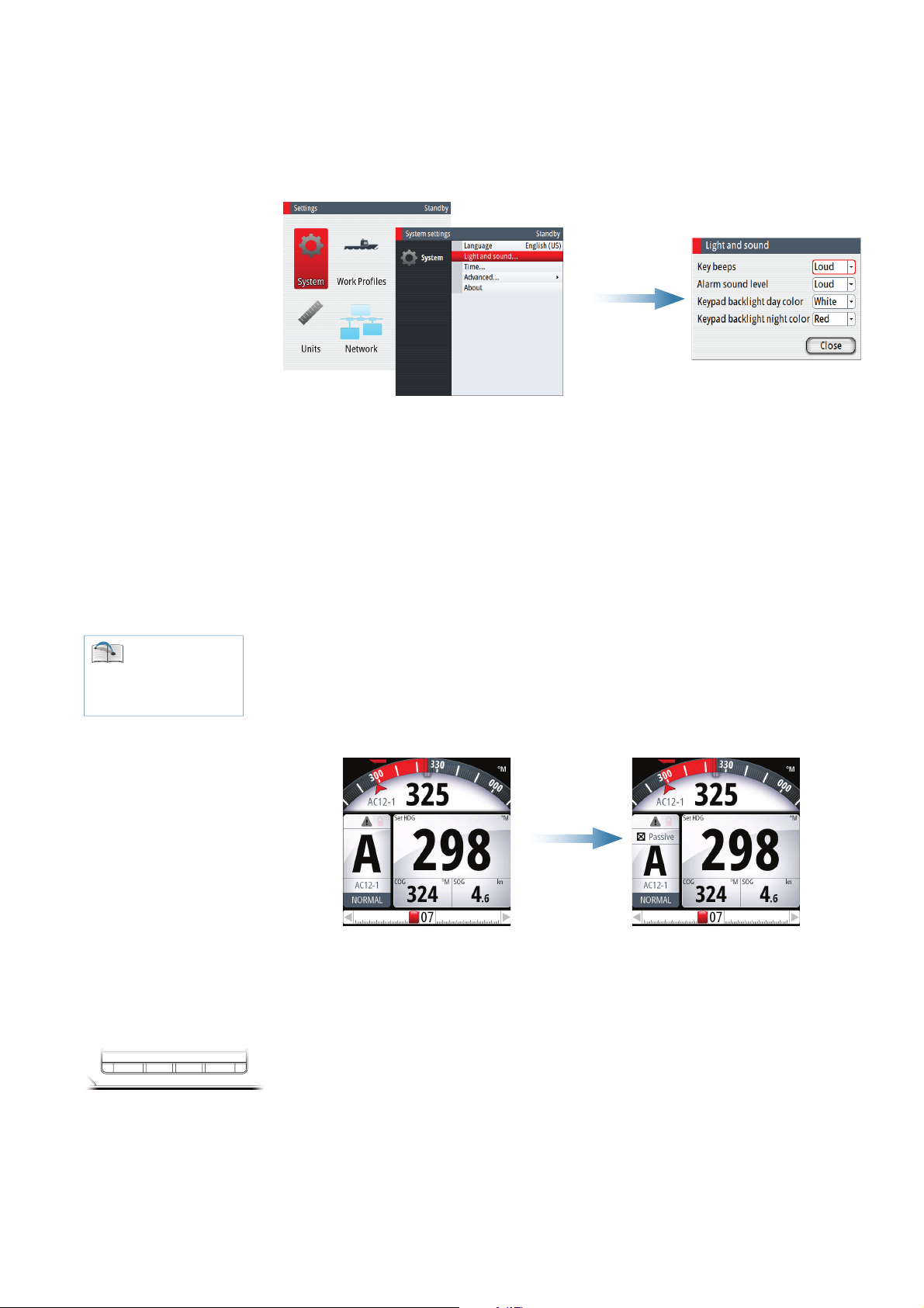
Day/Night illumination
S
A night illumination option is included. This optimizes the color palette for low light
conditions. You switch between Day and Night illumination mode from the Light dialog.
White is the default background color on display and keys for Day illumination, while red is
used for Night. You can select which of these colors you want to use.
Note: The brightness level are adjusted independently for day and night illumination.
Taking command
You can take command from any control unit and/or remote by pressing the CMD key.
In an open system (no command transfer restrictions) you will get immediate control from
the control unit requesting command. A steering handle without a CMD key will get control
when the lever is operated.
In a multi-station system with active lock function, the command request must be confi rmed
on the active control unit.
See “Delegation of
control in multiple station
systems” on page 14 for
further information
TBY AUTONAV WORK
Active/Passive units
In a system including more than one control unit and/or remote units, only one unit can be in
control at a time. All other units will be passive.
A passive unit is indicated in the mode status fi eld with passive icon, and the mode indication
letter size is reduced.
Active unit Passive unit
On a passive/locked unit illumination can be adjusted, alarm sound can be locally silenced,
and the CMD ke
y can be used for requesting command. All other functions are unavailable.
Selecting autopilot modes
You switch between Standby mode, Auto modes and Nav steering by pressing the
corresponding mode key.
When in Standby mode you can select NFU (Non Follow Up) by pressing the PORT or STBD
keys. Rudder will move and active trusters rotate as long as the key is pressed.
When in Standby or NFU mode you can select FU by pressing the rotary knob. The rudder
angle is then set by turning the rotary knob.
Basic operation | AP70/AP80 Operator Manual
| 11
Switching from automatic mode to hand steering
You can switch the autopilot to Standby mode from any operational mode by a short press
on the STBY key.
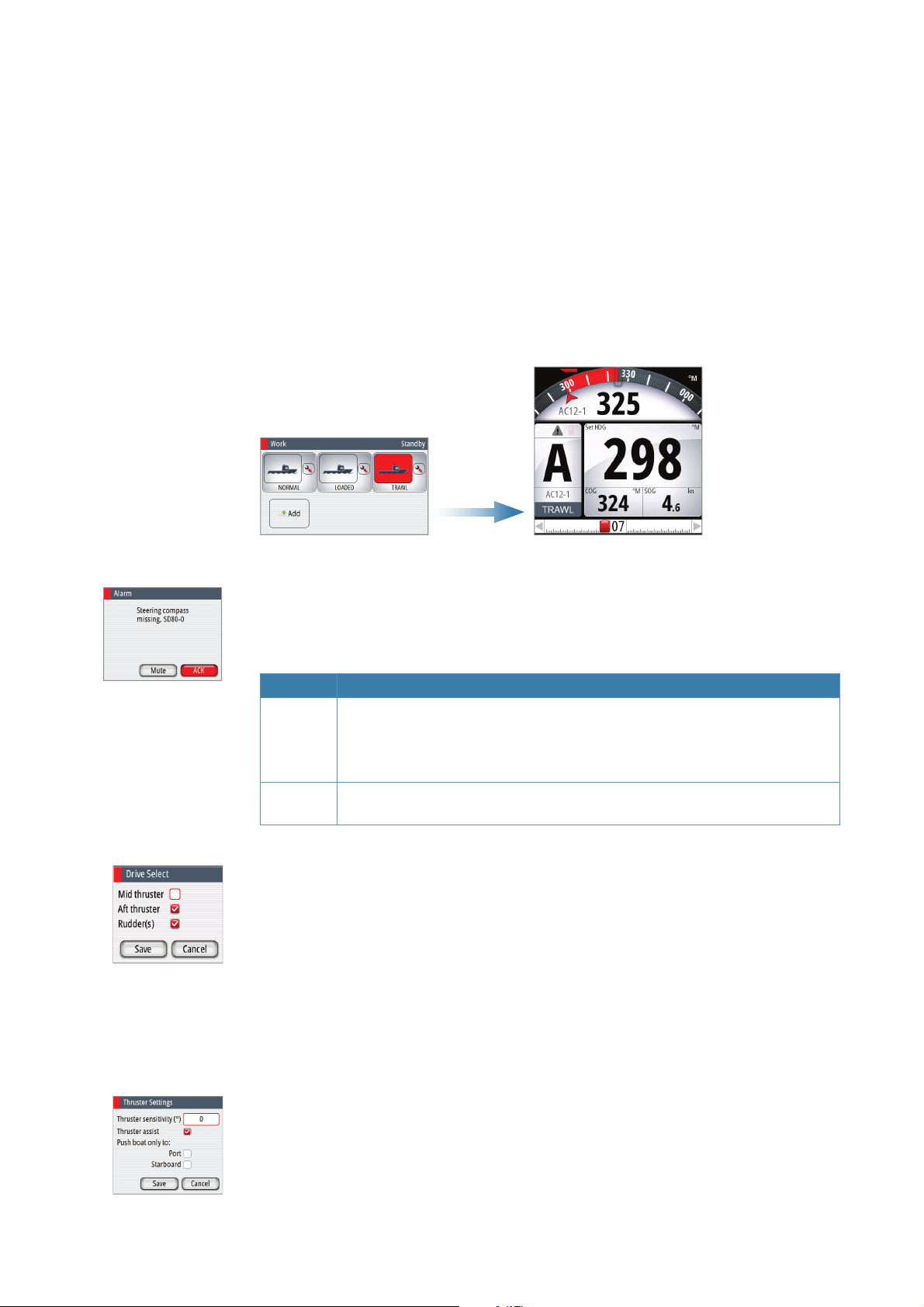
Selecting work pro les
The autopilot can be set up with 6 diff erent work profi les associated with diff erent work
modes or various crew members preferences.
1. Press the WORK key to open the Work dialog
2. Repeat pressing the WORK key or use the rotary knob to select preferred profi le
3. Press the rotary knob or the STBY key to confi rm your selection
The name of the work profi le in use is displayed in the mode status panel.
Acknowledging a message
When an alarm situation occurs, the alarm icon will be active, and the alarm dialog will show
alarm cause.
The following options are available in the alarm dialog for acknowledging a message:
Option Result
ACK Sets the alarm state to acknowledged, meaning that you are aware of the alarm
condition. The siren will stop and the alarm dialog will be removed.
The alarm icon will however remain active, and the alarm will be included in
the alarm listing until the reason for the alarm has been removed
Mute Mutes the siren locally for all units in the same SimNet display group. The alarm
dialog remains on the display
Working with thrusters
If the vessel is equipped with thrusters, they can be connected to the autopilot system. The
thrusters can be confi gured to diff erent work profi les, and work profi le in use will then decide
if the vessel can be controlled by rudder, thrusters, or both rudder and thrusters.
Thruster settings
Two settings aff ect how the thrusters are used by the autopilot:
• Thruster inhibit speed - set during dockside setup
- This setting will turn the thrusters off when the vessel is running above a set speed limit
Refer to the separate autopilot Installation manual.
12 |
• The thruster assist function - set when confi guring the thrusters for the work profi les.
- ON: the thrusters will automatically be used by the autopilot system. If the thrusters are
turned off when the vessel increases inhibited speed, the thrusters will automatically be
turned on again when the speed gets below the inhibited limit
- OFF: you must manually turn thrusters ON
For more information see “Work profi le setup” on page 30.
Basic operation | AP70/AP80 Operator Manual
Activating and de-activating thrusters
You can manually toggle thrusters on/off by pressing and holding the CMD key. A popup
with slide bar will be displayed as long as the key is pressed. The slider moves from hiding to
showing (or opposite) the thruster symbols.
Thruster(s) ON Slider moving Thruster(s) OFF
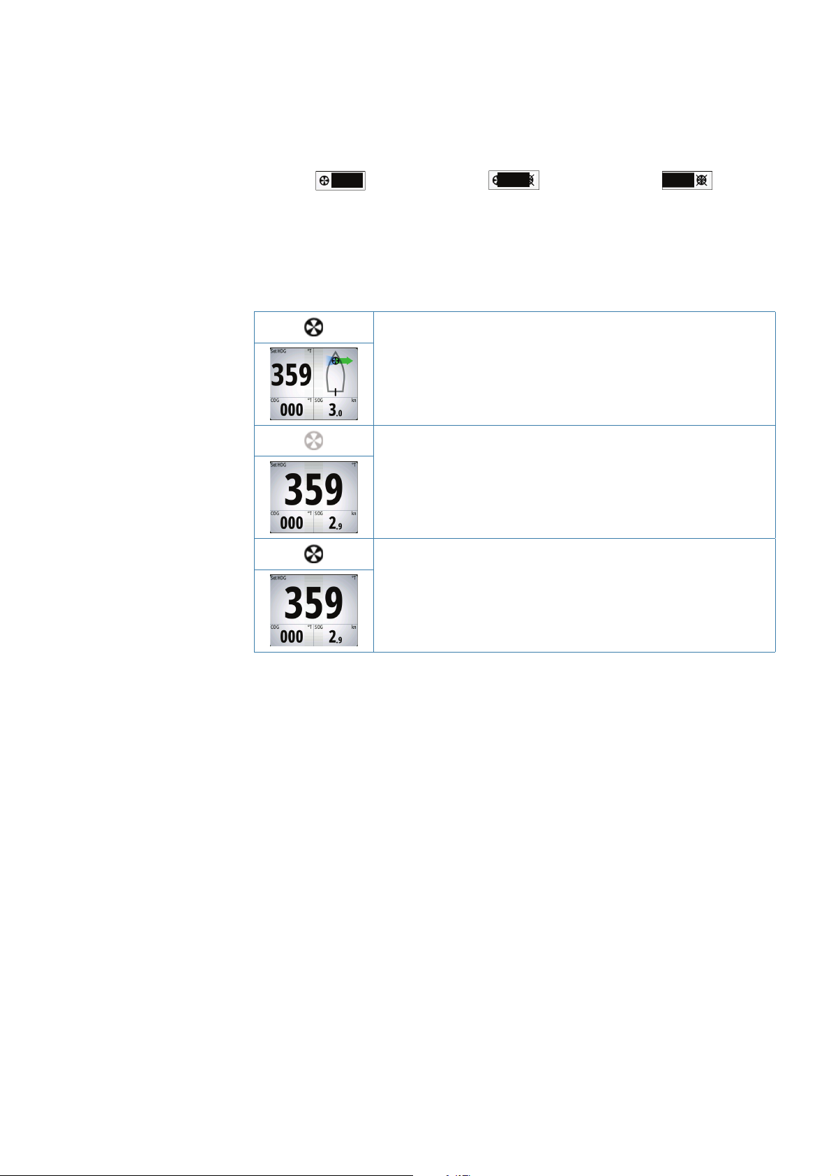
Thruster presentation
When thrusters are installed, the thruster status icon and the thruster information in the mode
info panel are as shown below.
• Thrusters installed and in use
• Thruster(s) installed, but not confi gured for present work profi le
• Thruster(s) installed, but unavailable (vessel speed is above inhibit
limit)
• Thruster(s) available, but turned OFF
Basic operation | AP70/AP80 Operator Manual
| 13
3
Delegation of control in multiple station systems
Steering stations
An autopilot system with multiple stations can be set up with diff erent
steering stations (SimNet group settings - Station). This setting is done
during installation of the system, and the separate autopilot Installation
manual details how to defi ne SimNet groups.
The SimNet group Station settings determines lock/unlock and
command transfer principle between active and passive control units.
Based on this setting the system is defi ned as an open system or a
master system as described in the following sections.
On a locked unit you can only adjust illumination and silence an alarm
locally. All other functions are unavailable.
Open systems
In a default installation the system is open, and control is accessible from every control unit
connected to the autopilot system. One control unit is active and provides the user with
access to all functions. All remaining control units are inactive and have no eff ect on course
changes. A single press on the CMD key on an inactive control unit will allow transfer of
command and make the unit active. On steering levers without a command key (e.g. JS10,
S35, S9), command is taken by moving the lever.
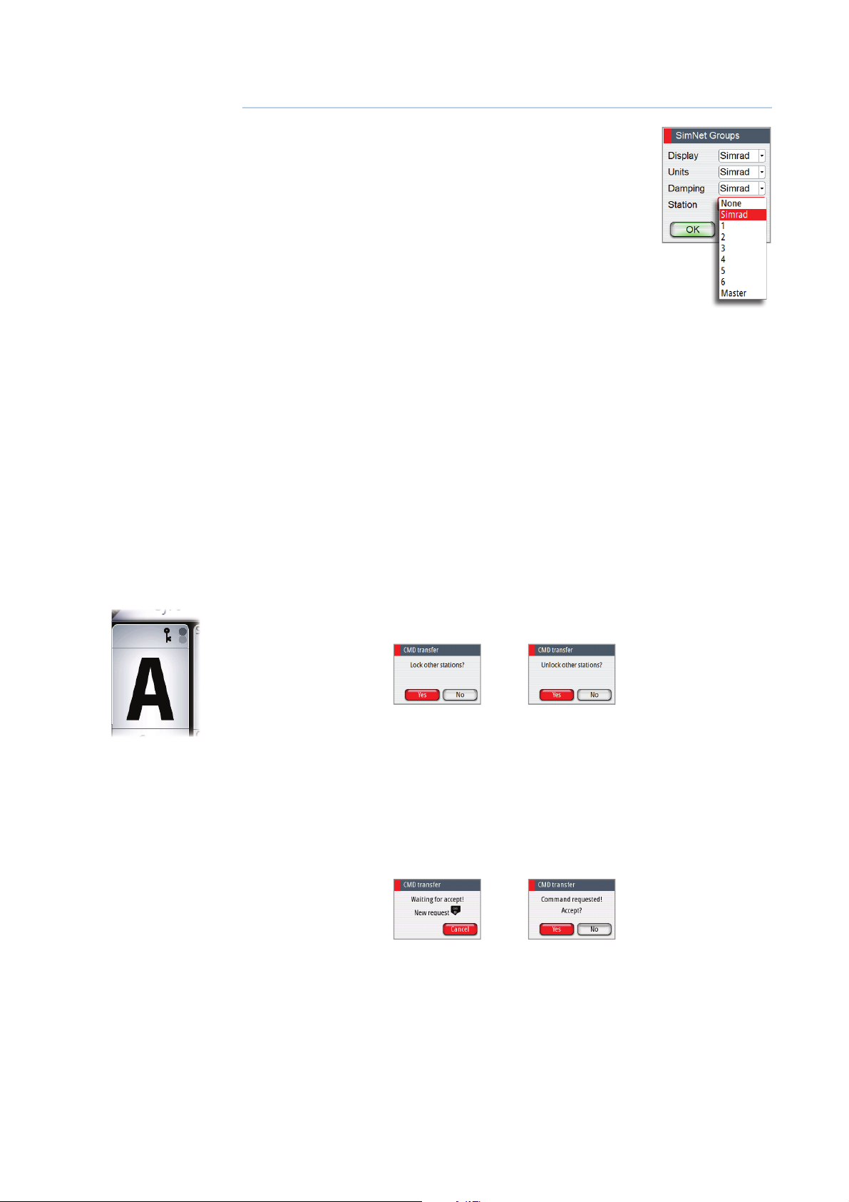
Locking and unlocking units in an open system
You can temporarily lock units in an open system if you want to avoid accidental control from
another control unit
An active AP70/AP80 control unit can lock and unlock all passive control units.
1. Activate the lock function from any active control unit by a single press on the CMD key
2. De-activate the function with a second press on the CMD key
Active locking function is indicated with a lock symbol on both active and passive units.
Taking command from a locked unit in an Open system
1. Press the CMD key on the locked unit
- A dialog will be shown on the unit requesting command
- A command request dialog will be shown on the active unit, accompanied by a 2 second
sound
14 |
Passive unit requesting
command
Delegation of control in multiple station systems | AP70/AP80 Operator Manual
Active unit accepting
command request
2. Accept the command request on the active unit
- All passive units will be opened for command transfer, indicated as below
- The lock function will be de-activated, and the lock symbol removed from all units
Passive units
3. Take command on selected remote unit
Master systems
The international standard for heading control systems (ISO 11674/16329) requires controlled
command transfer when remote stations are provided. The delegation of control to the
remote station and the return of control shall be incorporated in the autopilot system, and
shall avoid unintended operation from a remote station.
To fulfi ll this requirement the AP70/AP80 system includes a Master function. This is used in
Wheelmarked systems where you permanently want to control command transfer to remote
stations.
In a Master system, one steering station is defi ned as the Master station. There can be several
control units in a master station, but only one of them can be set as the Master unit.
All units included in the master station will be unlocked, and command transfer within the
master group will be as in an open system.
Units not included in the master station will be locked. It is not possible to take command
from units outside the master station unless the master control unit opens for this. All units
outside the master station will have a lock symbol.
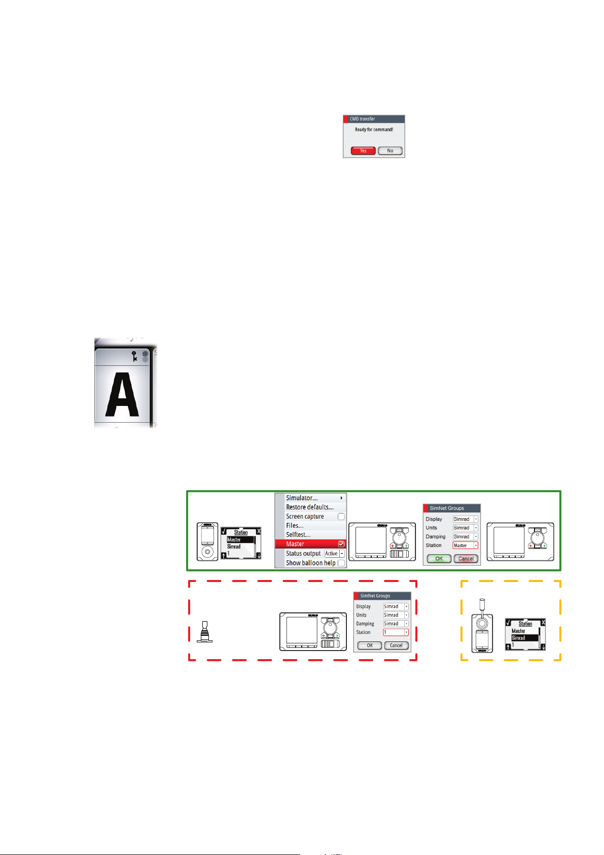
In the illustration below the main bridge is defi ned as master station. One QS80, one AP80
control unit and one AP70 control unit are included in the master station. The AP80 control
unit is defi ned as the Master unit.
The illustration includes SimNet group settings for each unit, showing how the units are
defi ned as part of diff erent SimNet stations.
AFT STATION
MAIN BRIDGE
3 3
WING STATION
3
Delegation of control in multiple station systems | AP70/AP80 Operator Manual
| 15
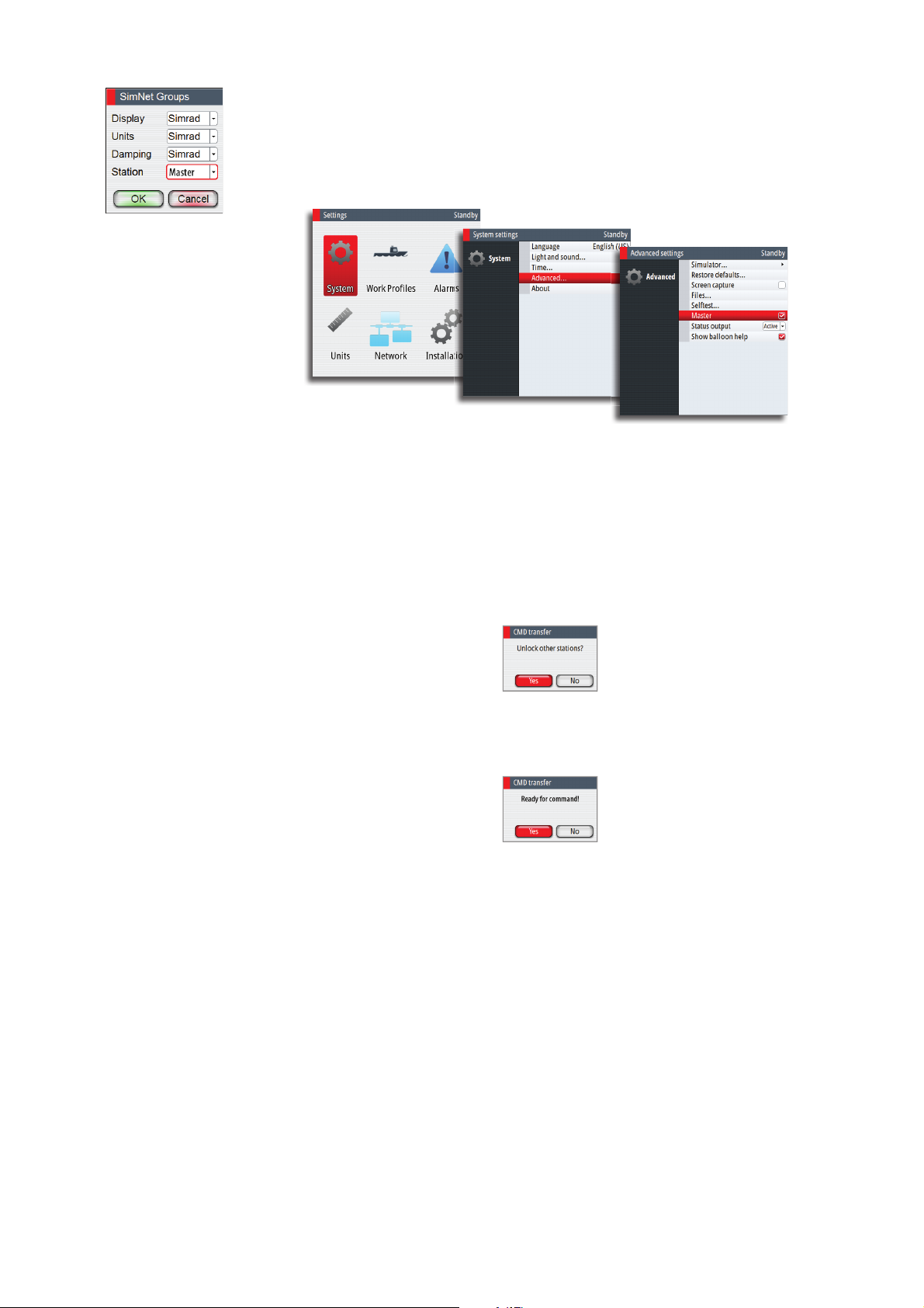
De ning a Master system
A master station is usually defi ned and units assigned to the master station during system
setup. Refer to the separate autopilot installation manual for details.
Note: When a SimNet group Station is set to Master, one control unit in this steering station
has to be defi ned as the Master unit as shown below.
In a Master system command can be transferred to a remote unit either by opening the
system for remote operation from the Master unit, or by requesting command from one of
the remote units.
Note: You can at any time return to control from the master station by pressing the CMD key
on one of the units in the master station.
Opening a Master system for operation from a remote unit
1. Press the CMD key on the Master unit
2. Accept the command request on the Master unit
- The system will now be open and command can be taken from any station
3. Take command on selected remote by pressing the CMD key
- Command will be transferred to this remote, accompanied by a 2 second sound
- All other remote units will return to locked status
16 |
Delegation of control in multiple station systems | AP70/AP80 Operator Manual

Taking command from a locked unit in a Master system
1. Press the CMD key on a locked station
- A dialog will be shown on the unit requesting command
- A command request dialog will be shown on the master unit
Passive unit requesting
command
2. Accept the command request on the master unit
- The requesting remote will now be opened for command transfer. All other units will
remain locked
3. Take command on requesting remote by pressing the CMD key
- Command will be transferred to this remote, accompanied by a 2 second sound
Active unit accepting
command request
Delegation of control in multiple station systems | AP70/AP80 Operator Manual
| 17

4
The operational modes
Mode overview
The autopilot has several steering modes. Number of modes and features within the mode
depend on available input as shown below.
MODE FEATURE DESCRIPTION REQUIRED INPUT
Standby mode used when manually
STBY
NFU
FU
AUTO
Heading
capture
Turn
(Pattern)
NoDrift
Heading
capture
NAV
steering at the helm. Compass and rudder
angle will be shown on the display
Non-Follow-Up steering where the rudder
movement is controlled by using the red
(port) or green (starboard) keys, or by
another NFU unit
Follow-up steering where the rudder
angle is set by the rotary knob or by
another FU unit
Auto compass mode. Keeps the vessel on
set heading
Aborts the turn and uses the
instantaneous compass reading as set
heading
Moves the vessel automatically in predefi ned turn steering patterns
Automatic steering, keeping the vessel on
a straight bearing line by compensating
for drift
Aborts the turn and uses the
instantaneous compass reading as set
heading
Navigation steering. The vessel is steered
to a specifi c waypoint location, or through
a route set on a chart plotter
Rudder feedback
Rudder feedback
Heading
Heading, speed, position
Heading, speed, Cross
Track Distance (XTD)
and Bearing waypoint to
waypoint (BWW)
See “Using an external
switch to control autopilot
operation” on page 9 for
further information
18 |
External system selector
An external switch can be used for controlling change over from manual to automatic
steering.
The mode descriptions in the following pages assumes that an external system selector has
opened for autopilot operation, or that no external selector is installed.
The operational modes | AP70/AP80 Operator Manual
 Loading...