

Page 1
AP70/AP80
Operator Manual
ENGLISH
Page 2

Page 3

Preface
Disclaimer
As Navico is continuously improving this product, we retain the right to make changes to the
product at any time which may not be refl ected in this version of the manual. Please contact
your nearest distributor if you require any further assistance.
It is the owner’s sole responsibility to install and use the equipment in a manner that will
not cause accidents, personal injury or property damage. The user of this product is solely
responsible for observing safe boating practices.
NAVICO HOLDING AS AND ITS SUBSIDIARIES, BRANCHES AND AFFILIATES DISCLAIM ALL
LIABILITY FOR ANY USE OF THIS PRODUCT IN A WAY THAT MAY CAUSE ACCIDENTS, DAMAGE
OR THAT MAY VIOLATE THE LAW.
Governing Language: This statement, any instruction manuals, user guides and other
information relating to the product (Documentation) may be translated to, or has been
translated from, another language (Translation). In the event of any confl ict between any
Translation of the Documentation, the English language version of the Documentation will be
the offi cial version of the Documentation.
This manual represents the product as at the time of printing. Navico Holding AS and its
subsidiaries, branches and affi liates reserve the right to make changes to specifi cations
without notice.
Compliance
The AP70 and AP80 systems complies with the following regulations:
• Wheelmark directive 2002/84 EC (HCS and HSC)
• CE (2004-108 EC EMC Directive) - AP70 systems when used with an AC70 computer
• C - Tick
Note: AP70 systems are not wheelmark approved when used with an AC70 computer.
For more information please refer to our websites:
pro.simrad-yachting.com and www.simrad-yachting.com.
The Wheelmark
The AP70 and AP80 system are produced and tested in accordance with the European Marine
Equipment Directive 96/98. This means that the systems comply with the highest level of
tests for nonmilitary marine electronic navigation equipment existing today.
The Marine Equipment Directive 96/98/EC (MED), as amended by 98/95/EC for ships fl ying
EU or EFTA fl ags, applies to all new ships, to existing ships not previously carrying such
equipment, and to ships having their equipment replaced.
This means that all system components covered by annex A1 must be type-approved
accordingly and must carry the Wheelmark, which is a symbol of conformity with the Marine
Equipment Directive.
While the autopilot system may be installed on vessels not needing to comply with the
Marine Equipment Directive, those requiring compliance must have one Control unit set-up
as a “master unit” in order for the installation to be approved.
Navico has no responsibility for the incorrect installation or use of the autopilot, so it
is essential for the person in charge of the installation to be familiar with the relevant
requirements as well as with the contents of the manuals, which covers correct installation
and use.
Copyright
Copyright © 2012 Navico Holding AS.
Preface | AP70/80 Operator Manual
| 1
Page 4

Warranty
The warranty card is supplied as a separate document.
In case of any queries, refer to the our websites:
pro.simrad-yachting.com and www.simrad-yachting.com.
About this manual
This manual is a reference guide for operating the Simrad AP70 and AP80 Autopilot Systems.
The manual will be continuously updated to match new software releases. The latest available
manual version can be downloaded from our web sites.
Important text that requires special attention from the reader is emphasized as follows:
Note: Used to draw the reader’s attention to a comment or some important information.
Warning: Used when it is necessary to warn personnel that they
should proceed carefully to prevent risk of injury and/or damage to
equipment/personnel.
2 |
Preface | AP70/80 Operator Manual
Page 5

Contents
5 Introduction
5 The front panel and keys
6 The screen
8 Operational mode overview
9 Basic operation
9 Safe operation with the autopilot
9 Using an external system selector to control autopilot operation
9 External follow-up override
10 Turning the autopilot system on/off
10 The menus
10 Dialog boxes
10 Display illumination
11 Ta k i n g command
11 Selecting autopilot modes
12 Switching from automatic mode to hand steering
12 Selecting work profi les
12 Acknowledging a message
12 Working with thrusters
14 Delegation of control in multiple station systems
14 Steerin g stations
14 Open systems
15 Master systems
18 The operational modes
18 M ode overview
18 External s ystem selector
19 Hand steering
20 AUTO modes
23 U-turn pattern steering
26 Controlling steering performance in automatic and navigational modes
27 Simulator mode
28 Work pro le setup
28 The Normal profi le
28 Creating new profi les
32 Edit a profi le
32 Importing and exporting work profi les (AP80 only)
34 The alarm system
34 Message types
34 Alarm indication
35 Acknowledging a message
35 The alarm dialogs
36 Setting the alarm and warning limits
36 Fallback and failures during automatic steering
37 List of possible alarms and corrective actions
Contents | AP70/AP80 Operator Manual
| 3
Page 6

42 Maintenance
42 Preventive maintenance
42 Simple maintenance procedures
42 Restoring factory default settings
43 Software upgrades
43 Backing up your system data
43 File management
44 Menu overview
44 The Quick menus
45 The settings dialog and submenus
47 System con guration
47 General
47 The settings dialog and submenus
47 Turning on for the fi rst time
48 Network settings
52 Installation settings
58 Seatrials
60 Tuning the autopilot for optimum steering performance
62 List of display abbreviations
4 |
Contents | AP70/AP80 Operator Manual
Page 7
1
Introduction
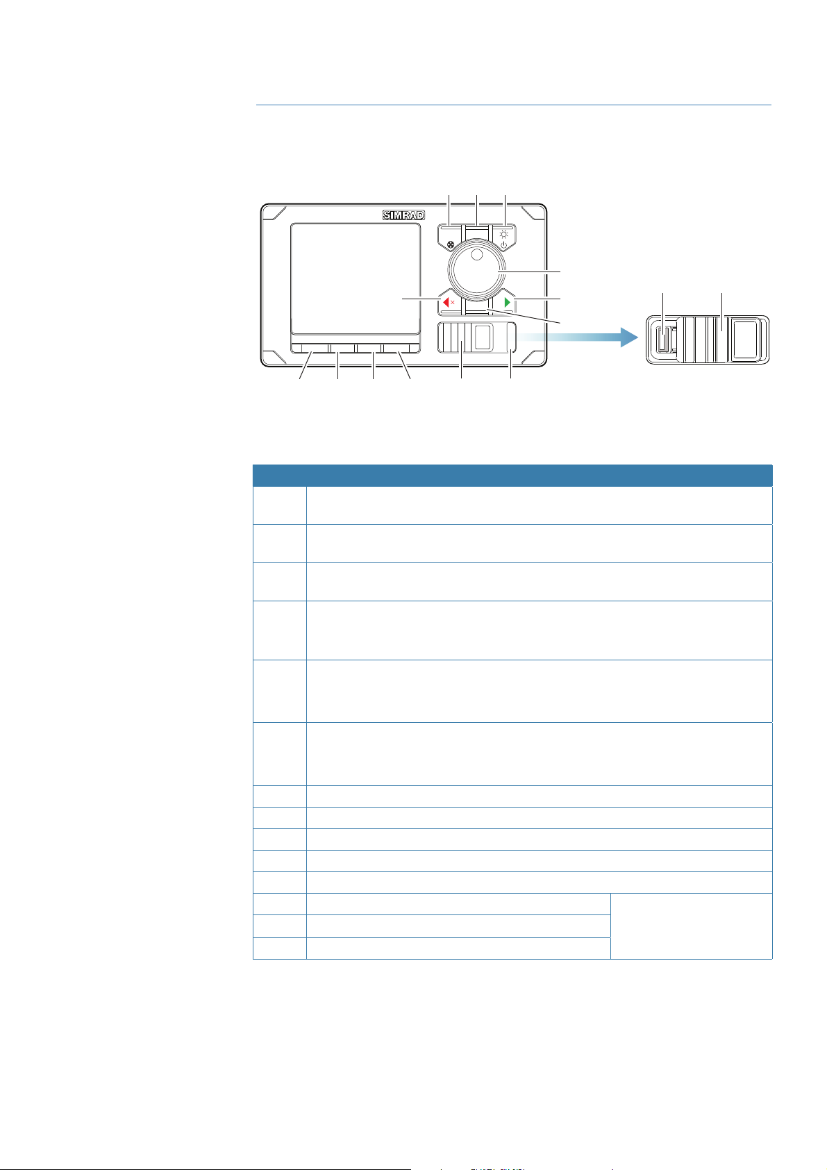
The front panel and keys
123
MENUCMD
5
TURN
4
3
6
14* 12*
7
STBY AUTO NAV WORK
91011
8
* Available on AP80 control units only.
No. Key/Description
1 CMD/THRUSTER. A short press takes/requests command. A long press (3
seconds) activates/deactivates available thrusters
2 MENU. A short press displays the active steering mode’s quick menu. A second
click displays the Settings menu
3 POWER/LIGHT. A short press displays the Light dialog. A long press (3 seconds)
turns the unit ON/OFF
4 ROTARY KNOB (Course wheel). Rotated for selecting menu item and adjusting
value, pressed to confi rm a selection/entry.
For mode specifi c operation, refer to “The operational modes” on page 17
5 PORT (Cancel). Exits menu/returns to previous menu level.
Activates NFU steering when in Standby mode.
Changes set heading, set course and track off set to port.
6 STBD (Confi rm). Confi rms menu selection/enters next menu level.
Activates NFU when in Standby mode.
Changes set heading, set course and track off set to starboard.
7 TURN. Displays the Turn dialog
8 STBY. Turns the autopilot to Standby mode
9 AUTO. Activates Auto and NoDrift mode
10 NAV (AP70) / TRACK (AP80). Activates Nav steering mode
11 WORK. Used for selecting work profi le
12 USB port door
13 ALARM. Displays the Alarm listing dialog
14 USB connector
12*
ALARM
13*
AP80 control units only
ALARM
Introduction | AP70/AP80 Operator Manual
| 5
Page 8
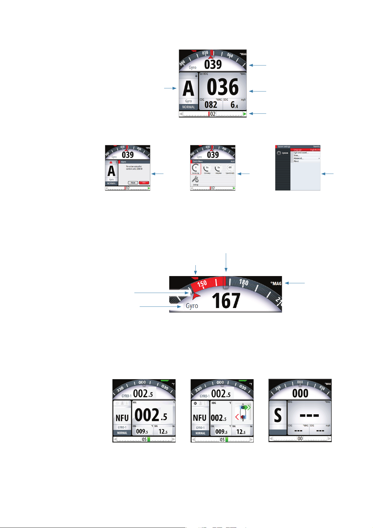
The screen
1
4
2
3
567
1 Heading repeater
Analog and digital heading readout. Digital readout is shown with one decimal if true
heading.
In automatic modes the diff erence between current and set heading is red for port, green for
starboard deviation.
Current heading
Rate indicator
Heading repeater
(
T
Set heading
Steering reference
2 Mode Info panel
The panel contains mode specifi c content and varies with the operational mode. See “The
operational modes” on page 17 onwards for more details.
If a thruster is available and active, the mode info panel will be split to show thruster
information.
If sensor input is missing, the numbers will be replaced with hyphens.
No active trusters Active thrusters No sensor input
rue or Magnetic)
unit
6 |
Introduction | AP70/AP80 Operator Manual
Page 9
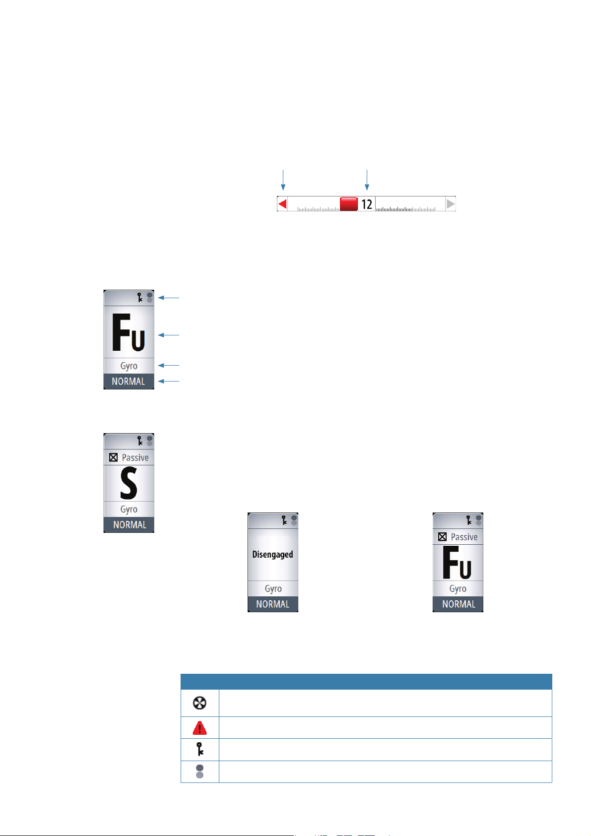
3 Rudder bar
Rudder position indicator with digital and analog readout.
The digital readout shows 1 bar per 1° rudder angle up to 40°. Rudder angle above 40° will
have a non-linear indication in the outer left/right part of the bar.
Direction indicators are turning red (port) and green (starboard) when rudder movement is
commanded. The direction arrows are only shown when rudder feedback is available.
C
ommanded
rudder dir
ection
* Showing commanded rudder angle in systems with analog steering without rudder
feedback.
4 Status panel
Status icons
The following mode abbreviations are used:
Rudder angle *
S: Standby
Mode indication
Steering reference
Active work pro le
If the autopilot is operated from another unit, this is shown in the mode indication fi eld.
If the autopilot is controlled by an external system selector or by an external follow-up, the
mode indication will be replaced as below.
FU: Follow Up
NFU: Non Follow Up
A: Auto heading
ND: No Drift
N: Nav
Autopilot disengaged by external system selector Rudder controlled by external follow-up
Available status icons are shown below. Only active icons will be visible.
Icon Description
Icon available if one or more thrusters are installed. The icon will be shaded when
the trusters are unavailable for steering
Active alarm message. Red icon for alarms, yellow for warnings
Control unit locked
Screen alive indication - white and black “balls” fade-swap color
Introduction | AP70/AP80 Operator Manual
| 7
Page 10
5 Dialogs
Used for user input or for presenting information to the user.
A dialog may be presented in full-screen or as an overlay. Depending on type of information
or entry, diff erent keys are used to confi rm, cancel and close the dialog.
A dialog can always be closed by selecting the Close/Cancel dialog key, or by pressing the
PORT key.
6 Quick menus
Mode dependant menu, displayed by pressing the MENU key. The Quick menus contain the
most common used settings for the active mode. The menu varies with the autopilot mode
and also with the way the autopilot is operated.
7 Settings menus
Used for installation and system setup. The menus are activated from the quick menu, or by
pressing the MENU key twice.
Operational mode overview
The autopilot has several steering modes. Number of modes and features within the mode
depend on available input as shown below.
The modes are described in “The operational modes” on page 17.
MODE FEATURE DESCRIPTION
STBY
NFU
FU
AUTO Auto compass mode. Keeps the vessel on set heading
Heading
capture
Turn
(Pattern)
NoDrift
Heading
capture
NAV
Standby mode used when manually steering at the helm. Compass
and rudder angle will be shown on the display
Non-Follow-Up steering where the rudder movement is controlled by
using the red (port) or green (starboard) keys, or by another NFU unit
Follow-up steering where the rudder angle is set by the rotary knob or
by another FU unit
Aborts the turn and uses the instantaneous compass reading as set
heading
Moves the vessel automatically in pre-defi ned turn steering patterns
Automatic steering, keeping the vessel on a straight bearing line by
compensating for drift
Aborts the turn and uses the instantaneous compass reading as set
heading
Navigation steering. The vessel is steered to a specifi c waypoint
location, or through a route set on a chart plotter
8 |
Introduction | AP70/AP80 Operator Manual
Page 11
2
Basic operation
Safe operation with the autopilot
Warning: An autopilot is a useful navigational aid, but DOES NOT
under any circumstances replace a human navigator.
Do not use automatic steering when:
• In heavy traffi c areas or in narrow waters
• In poor visibility or extreme sea conditions
• When in areas where use of autopilot is prohibited by law
When using an autopilot:
• Do not leave the helm unattended
• Do not place any magnetic material or equipment near the magnetic or fl uxgate compass
used in the autopilot system
• Verify the course and position of the vessel at regular intervals
• Always switch to Standby mode, and reduce speed in suffi cient time to avoid hazardous
situations
Using an external system selector to control autopilot
operation
IMO resolution MSC64 and other regulations require that an external switch is used for
changing over from manual to automatic steering.
Manual steering
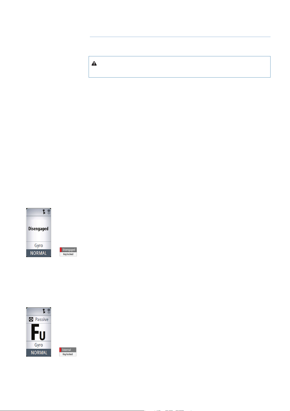
When an external system selector is set to manual steering, the autopilot will be disengaged.
The control unit will display information as in Standby mode. It is not possible to change to
FU, NFU or to any automatic mode. The menus can however be used, alarms acknowledged
and illumination adjusted.
When the autopilot is disengaged by an external switch, this will be indicated in the mode
display.
When a mode key is pressed, a dialog will show that the autopilot system is disengaged.
Autopilot operation
When the external selector is set to automatic steering, the autopilot will go directly to AUTO
heading mode with present heading as set reference. The autopilot can then be used in all
operational modes.
External follow-up override
On some autopilot computers you can connect a switch for allowing an external follow-up to
override autopilot control of the rudder. Refer the autopilot installation manual for connection
details.
When external follow-up override is selected, it is not possible to use any mode keys. The
menus can however be used, alarms acknowledged and illumination adjusted.
When the rudder is controlled by an external FU, this will be indicated in the mode display.
If you press a mode key, external control is indicated in the display.
Basic operation | AP70/AP80 Operator Manual
| 9
Page 12
Turning the autopilot system on/o
You turn ON the autopilot system on by a short press on the POWER key when this is red
light colored.
The system is turned OFF (Sleep mode) by pressing and holding the POWER key on an active
control unit. During the shut-down procedure the system will automatically go to Standby
mode before it is turned off . If the POWER key is released before shut-down is completed,
the power off is cancelled.
Note: The POWER key will remain lit on units that are turned OFF. Note: To stop the system
from drawing current a separate breaker should be installed.
The menus
You display a menu by pressing the MENU key.
• Use the rotary knob to select a menu item, then press the rotary knob or the STBD key to
confi rm your selection
• Toggle on /off a check box by pressing the rotary knob or the STBD key
• Activate a slide bar by pressing the rotary knob or the STBD key, then select the value by
turning the rotary knob. Confi rm your selection by pressing the rotary knob or the STBD key
• Expand a Drop-down listing by pressing the rotary knob or the STBD key, then select the
item by turning the rotary knob. Confi rm your selection by pressing the rotary knob or the
STBD key
• Press the PORT key to return to previous menu level. Repeat pressing the PORT key to exit
the menus.
Check box Slide bar Drop-down listing
Dialog boxes
You select entry fi elds and keys in a dialog box by using the rotary knob. You can only enter
information when a fi eld is selected and highlighted.
You exit a dialog and cancel your entries by selecting the Cancel key in the dialog, or by
pressing the PORT key.
You confi rm your entries and close the dialog by selecting the OK key in the dialog, or by
pressing the STBD key.
An alphanumeric keyboard will automatically be displayed when
required for entering user information in dialogs.
1. Select characters by turning the rotary knob
2. Confi rm your entry by pressing the rotary knob
3. Complete your entry by pressing the Enter key on the virtual
keyboard
Display illumination
Light adjustment
A single press on the POWER key will display the light adjustment dialog. The brightness
level is adjusted by the rotary knob.
Repeated presses on the POWER key will toggle between preset brightness levels (10 - 6 - 3-
1).
10 |
Basic operation | AP70/AP80 Operator Manual
Page 13
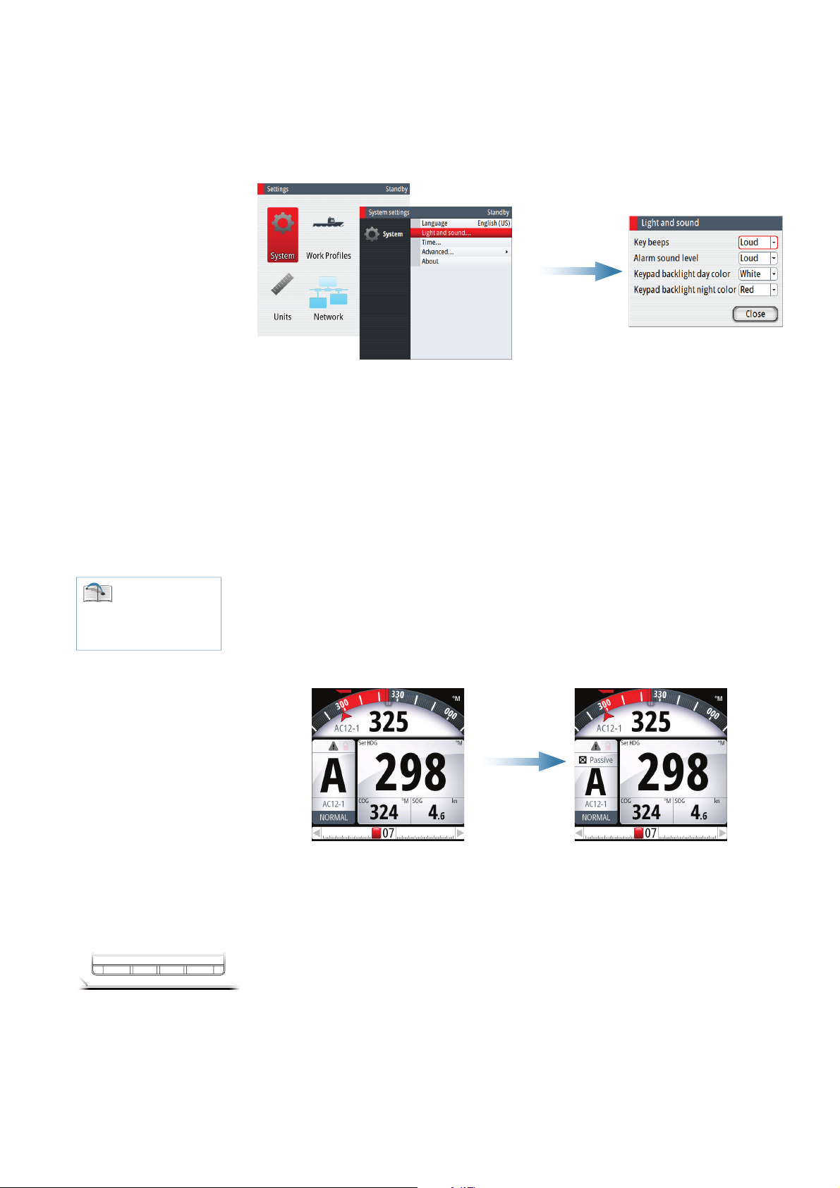
Day/Night illumination
S
A night illumination option is included. This optimizes the color palette for low light
conditions. You switch between Day and Night illumination mode from the Light dialog.
White is the default background color on display and keys for Day illumination, while red is
used for Night. You can select which of these colors you want to use.
Note: The brightness level are adjusted independently for day and night illumination.
Taking command
You can take command from any control unit and/or remote by pressing the CMD key.
In an open system (no command transfer restrictions) you will get immediate control from
the control unit requesting command. A steering handle without a CMD key will get control
when the lever is operated.
In a multi-station system with active lock function, the command request must be confi rmed
on the active control unit.
See “Delegation of
control in multiple station
systems” on page 14 for
further information
TBY AUTONAV WORK
Active/Passive units
In a system including more than one control unit and/or remote units, only one unit can be in
control at a time. All other units will be passive.
A passive unit is indicated in the mode status fi eld with passive icon, and the mode indication
letter size is reduced.
Active unit Passive unit
On a passive/locked unit illumination can be adjusted, alarm sound can be locally silenced,
and the CMD ke
y can be used for requesting command. All other functions are unavailable.
Selecting autopilot modes
You switch between Standby mode, Auto modes and Nav steering by pressing the
corresponding mode key.
When in Standby mode you can select NFU (Non Follow Up) by pressing the PORT or STBD
keys. Rudder will move and active trusters rotate as long as the key is pressed.
When in Standby or NFU mode you can select FU by pressing the rotary knob. The rudder
angle is then set by turning the rotary knob.
Basic operation | AP70/AP80 Operator Manual
| 11
Page 14
Switching from automatic mode to hand steering
You can switch the autopilot to Standby mode from any operational mode by a short press
on the STBY key.
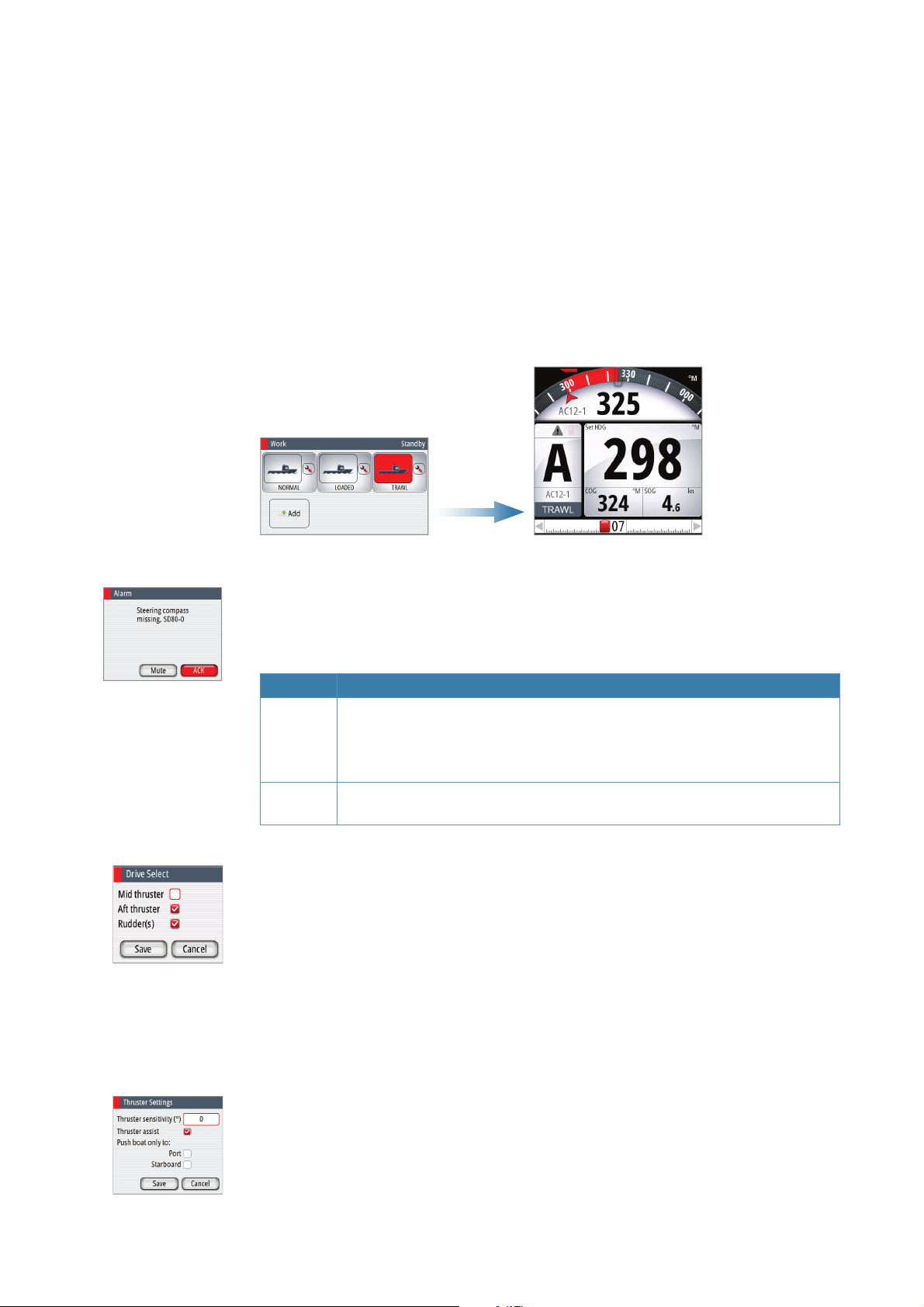
Selecting work pro les
The autopilot can be set up with 6 diff erent work profi les associated with diff erent work
modes or various crew members preferences.
1. Press the WORK key to open the Work dialog
2. Repeat pressing the WORK key or use the rotary knob to select preferred profi le
3. Press the rotary knob or the STBY key to confi rm your selection
The name of the work profi le in use is displayed in the mode status panel.
Acknowledging a message
When an alarm situation occurs, the alarm icon will be active, and the alarm dialog will show
alarm cause.
The following options are available in the alarm dialog for acknowledging a message:
Option Result
ACK Sets the alarm state to acknowledged, meaning that you are aware of the alarm
condition. The siren will stop and the alarm dialog will be removed.
The alarm icon will however remain active, and the alarm will be included in
the alarm listing until the reason for the alarm has been removed
Mute Mutes the siren locally for all units in the same SimNet display group. The alarm
dialog remains on the display
Working with thrusters
If the vessel is equipped with thrusters, they can be connected to the autopilot system. The
thrusters can be confi gured to diff erent work profi les, and work profi le in use will then decide
if the vessel can be controlled by rudder, thrusters, or both rudder and thrusters.
Thruster settings
Two settings aff ect how the thrusters are used by the autopilot:
• Thruster inhibit speed - set during dockside setup
- This setting will turn the thrusters off when the vessel is running above a set speed limit
Refer to the separate autopilot Installation manual.
12 |
• The thruster assist function - set when confi guring the thrusters for the work profi les.
- ON: the thrusters will automatically be used by the autopilot system. If the thrusters are
turned off when the vessel increases inhibited speed, the thrusters will automatically be
turned on again when the speed gets below the inhibited limit
- OFF: you must manually turn thrusters ON
For more information see “Work profi le setup” on page 30.
Basic operation | AP70/AP80 Operator Manual
Page 15
Activating and de-activating thrusters
You can manually toggle thrusters on/off by pressing and holding the CMD key. A popup
with slide bar will be displayed as long as the key is pressed. The slider moves from hiding to
showing (or opposite) the thruster symbols.
Thruster(s) ON Slider moving Thruster(s) OFF
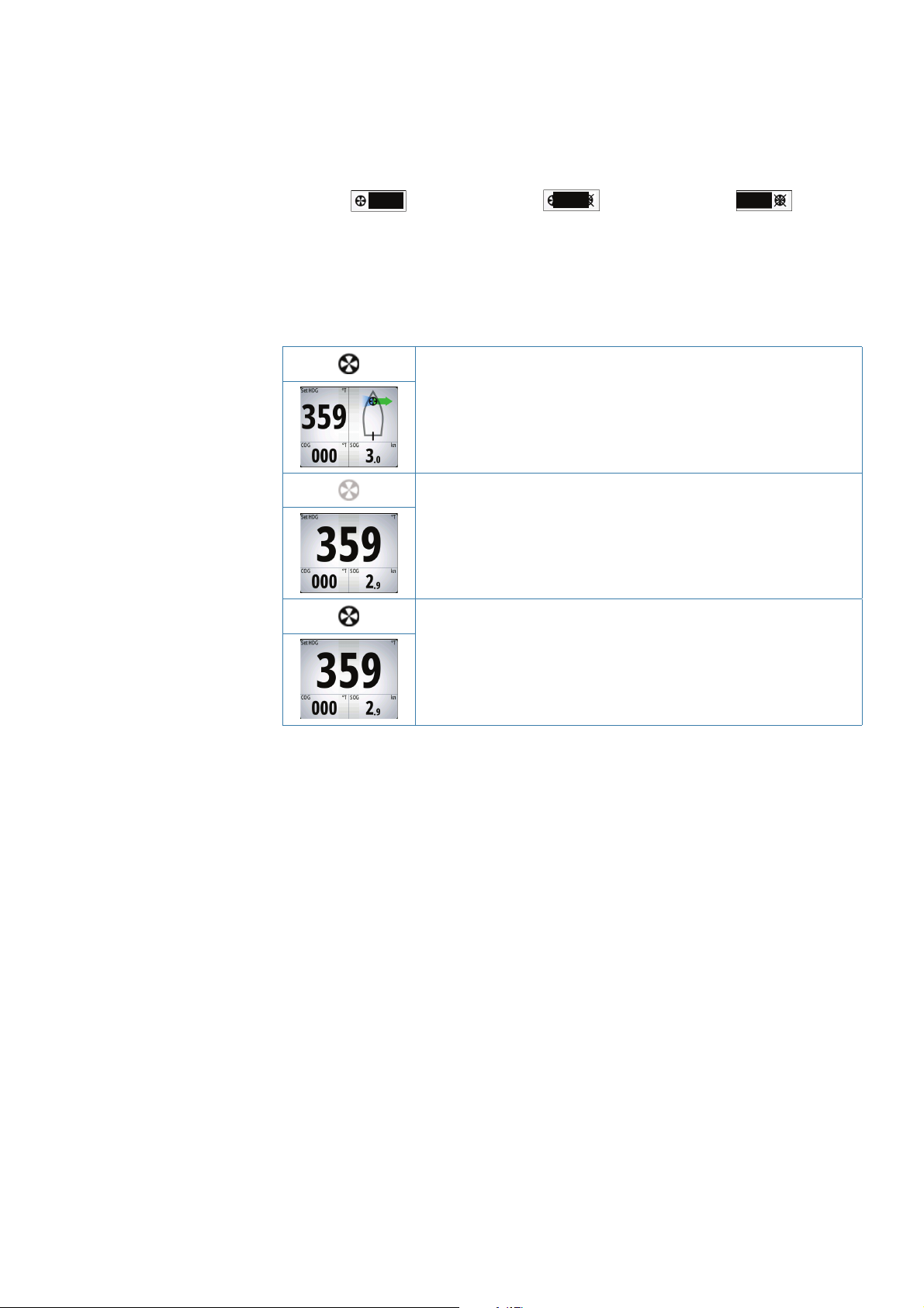
Thruster presentation
When thrusters are installed, the thruster status icon and the thruster information in the mode
info panel are as shown below.
• Thrusters installed and in use
• Thruster(s) installed, but not confi gured for present work profi le
• Thruster(s) installed, but unavailable (vessel speed is above inhibit
limit)
• Thruster(s) available, but turned OFF
Basic operation | AP70/AP80 Operator Manual
| 13
Page 16
3
Delegation of control in multiple station systems
Steering stations
An autopilot system with multiple stations can be set up with diff erent
steering stations (SimNet group settings - Station). This setting is done
during installation of the system, and the separate autopilot Installation
manual details how to defi ne SimNet groups.
The SimNet group Station settings determines lock/unlock and
command transfer principle between active and passive control units.
Based on this setting the system is defi ned as an open system or a
master system as described in the following sections.
On a locked unit you can only adjust illumination and silence an alarm
locally. All other functions are unavailable.
Open systems
In a default installation the system is open, and control is accessible from every control unit
connected to the autopilot system. One control unit is active and provides the user with
access to all functions. All remaining control units are inactive and have no eff ect on course
changes. A single press on the CMD key on an inactive control unit will allow transfer of
command and make the unit active. On steering levers without a command key (e.g. JS10,
S35, S9), command is taken by moving the lever.
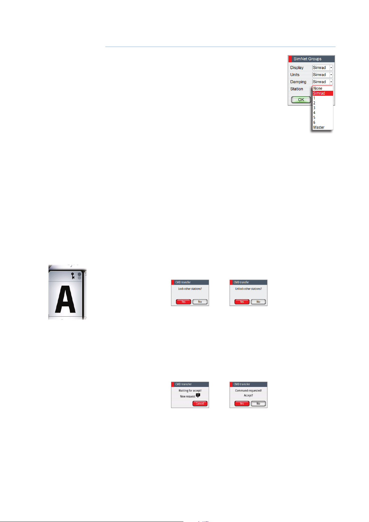
Locking and unlocking units in an open system
You can temporarily lock units in an open system if you want to avoid accidental control from
another control unit
An active AP70/AP80 control unit can lock and unlock all passive control units.
1. Activate the lock function from any active control unit by a single press on the CMD key
2. De-activate the function with a second press on the CMD key
Active locking function is indicated with a lock symbol on both active and passive units.
Taking command from a locked unit in an Open system
1. Press the CMD key on the locked unit
- A dialog will be shown on the unit requesting command
- A command request dialog will be shown on the active unit, accompanied by a 2 second
sound
14 |
Passive unit requesting
command
Delegation of control in multiple station systems | AP70/AP80 Operator Manual
Active unit accepting
command request
Page 17
2. Accept the command request on the active unit
- All passive units will be opened for command transfer, indicated as below
- The lock function will be de-activated, and the lock symbol removed from all units
Passive units
3. Take command on selected remote unit
Master systems
The international standard for heading control systems (ISO 11674/16329) requires controlled
command transfer when remote stations are provided. The delegation of control to the
remote station and the return of control shall be incorporated in the autopilot system, and
shall avoid unintended operation from a remote station.
To fulfi ll this requirement the AP70/AP80 system includes a Master function. This is used in
Wheelmarked systems where you permanently want to control command transfer to remote
stations.
In a Master system, one steering station is defi ned as the Master station. There can be several
control units in a master station, but only one of them can be set as the Master unit.
All units included in the master station will be unlocked, and command transfer within the
master group will be as in an open system.
Units not included in the master station will be locked. It is not possible to take command
from units outside the master station unless the master control unit opens for this. All units
outside the master station will have a lock symbol.
In the illustration below the main bridge is defi ned as master station. One QS80, one AP80
control unit and one AP70 control unit are included in the master station. The AP80 control
unit is defi ned as the Master unit.
The illustration includes SimNet group settings for each unit, showing how the units are
defi ned as part of diff erent SimNet stations.
AFT STATION
MAIN BRIDGE
3 3
WING STATION
3
Delegation of control in multiple station systems | AP70/AP80 Operator Manual
| 15
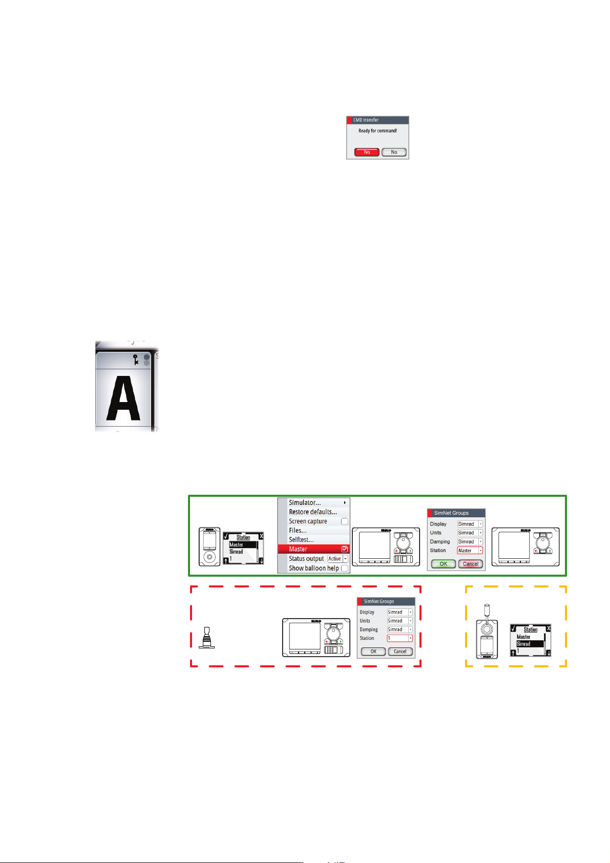
Page 18
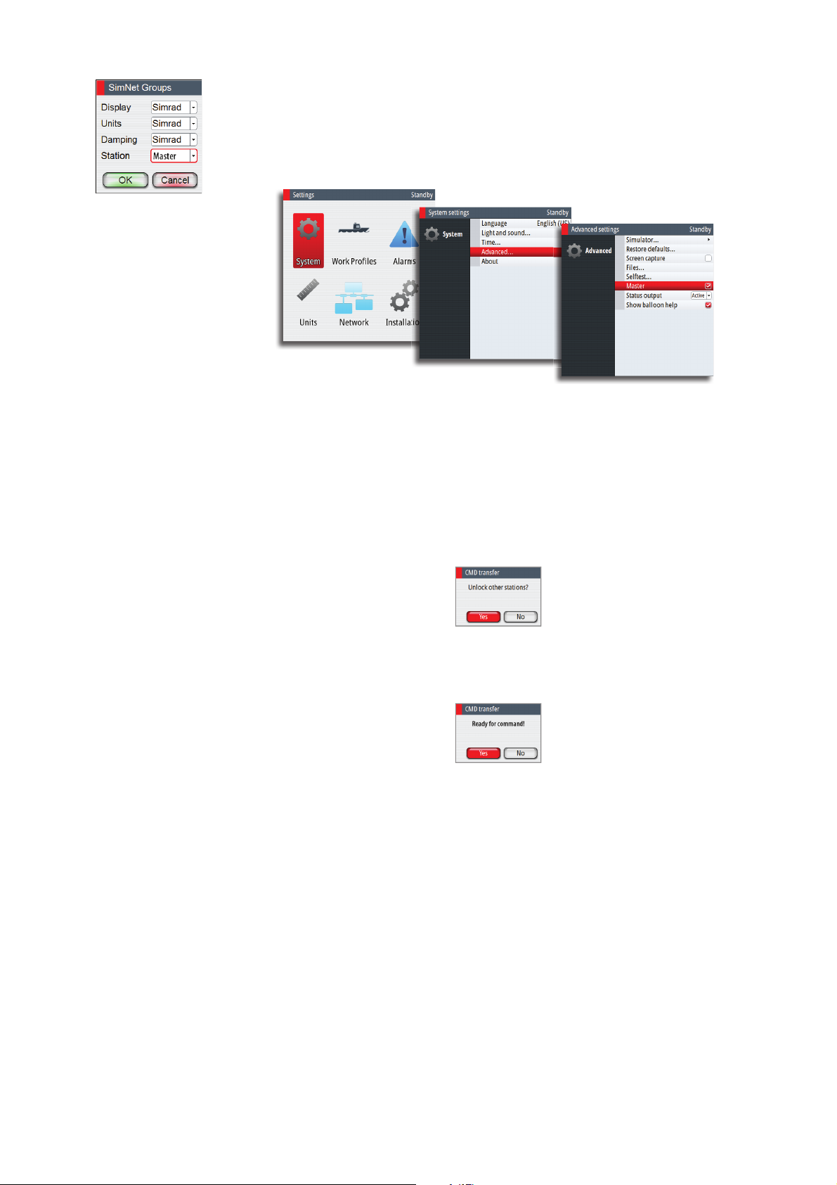
De ning a Master system
A master station is usually defi ned and units assigned to the master station during system
setup. Refer to the separate autopilot installation manual for details.
Note: When a SimNet group Station is set to Master, one control unit in this steering station
has to be defi ned as the Master unit as shown below.
In a Master system command can be transferred to a remote unit either by opening the
system for remote operation from the Master unit, or by requesting command from one of
the remote units.
Note: You can at any time return to control from the master station by pressing the CMD key
on one of the units in the master station.
Opening a Master system for operation from a remote unit
1. Press the CMD key on the Master unit
2. Accept the command request on the Master unit
- The system will now be open and command can be taken from any station
3. Take command on selected remote by pressing the CMD key
- Command will be transferred to this remote, accompanied by a 2 second sound
- All other remote units will return to locked status
16 |
Delegation of control in multiple station systems | AP70/AP80 Operator Manual
Page 19

Taking command from a locked unit in a Master system
1. Press the CMD key on a locked station
- A dialog will be shown on the unit requesting command
- A command request dialog will be shown on the master unit
Passive unit requesting
command
2. Accept the command request on the master unit
- The requesting remote will now be opened for command transfer. All other units will
remain locked
3. Take command on requesting remote by pressing the CMD key
- Command will be transferred to this remote, accompanied by a 2 second sound
Active unit accepting
command request
Delegation of control in multiple station systems | AP70/AP80 Operator Manual
| 17
Page 20

4
The operational modes
Mode overview
The autopilot has several steering modes. Number of modes and features within the mode
depend on available input as shown below.
MODE FEATURE DESCRIPTION REQUIRED INPUT
Standby mode used when manually
STBY
NFU
FU
AUTO
Heading
capture
Turn
(Pattern)
NoDrift
Heading
capture
NAV
steering at the helm. Compass and rudder
angle will be shown on the display
Non-Follow-Up steering where the rudder
movement is controlled by using the red
(port) or green (starboard) keys, or by
another NFU unit
Follow-up steering where the rudder
angle is set by the rotary knob or by
another FU unit
Auto compass mode. Keeps the vessel on
set heading
Aborts the turn and uses the
instantaneous compass reading as set
heading
Moves the vessel automatically in predefi ned turn steering patterns
Automatic steering, keeping the vessel on
a straight bearing line by compensating
for drift
Aborts the turn and uses the
instantaneous compass reading as set
heading
Navigation steering. The vessel is steered
to a specifi c waypoint location, or through
a route set on a chart plotter
Rudder feedback
Rudder feedback
Heading
Heading, speed, position
Heading, speed, Cross
Track Distance (XTD)
and Bearing waypoint to
waypoint (BWW)
See “Using an external
switch to control autopilot
operation” on page 9 for
further information
18 |
External system selector
An external switch can be used for controlling change over from manual to automatic
steering.
The mode descriptions in the following pages assumes that an external system selector has
opened for autopilot operation, or that no external selector is installed.
The operational modes | AP70/AP80 Operator Manual
Page 21

Hand steering
Standby mode
Standby mode is used when you steer at the helm. The autopilot will always be in this mode
when you turn the system on.
• Switch the autopilot to Standby mode from any operation by a short press on the STBY key.
The Standby mode info panel
A. HDG: Current heading and Header repeater unit (True or Magnetic)
A
BC
A
BC
B. COG: Course over ground
C. SOG: Speed over ground
- If SOG is missing, the speed info will be taken from log (STW). If also log is missing or
erratic, speed can be set manually from the Quick menu (MAN).
Non-Follow-Up (NFU) steering
In NFU mode you use the PORT/STBD keys to control the rudder.
• Select NFU mode by pressing the PORT or STBD keys when the autopilot is in Standby or
FU mode
- The the rudder will move as long as the key is pressed
The NFU mode info panel
A. HDG: Current heading and Header repeater unit (True or Magnetic)
B. COG: Course over ground
C. SOG: Speed over ground
- If SOG is missing, the speed info will be taken from log (STW). If also log is missing or
erratic, speed can be set manually from the Quick menu (MAN).
Follow-up (FU) steering
In FU mode you use the rotary knob to set rudder angle.
• Select FU mode by pressing the rotary knob when the system is in Standby or NFU mode
• Turn the rotary knob to set the rudder angle
- The rudder will move to the commanded angle and then stop
A
BC
FU mode info panel
A. Set rudder angle
B. COG: Course over ground
C. SOG: Speed over ground
- If SOG is missing, the speed info will be taken from log (STW). If also log is missing or
erratic, speed can be set manually from the Quick menu (MAN).
Quick menu in STBY, FU and NFU mode
From the Quick menu in STBY, NFU and FU you can change sources used for steering, display
active alarms and set manual speed.
The Quick menu includes access to the Settings dialogs.
• Activate the Quick menu by a short press on the MENU key
The operational modes | AP70/AP80 Operator Manual
| 19
Page 22

Source selection
Gives access to automatic and manual source selection menus.
Source setup is done on initial start up of the system. It is also required to run the source
selection if any part of the network has been changed or replaced.
See the separate AP70/AP80 Installation manual for more details.
Automatic source selection
The Auto Select option will look for all sources connected to the network. If more than one
source is available for each data type, the system will automatically select from an internal
priority list.
Make sure all devices are connected and are turned on before selecting the Auto Select
option.
Manual source selection
This option allows you to manually select sources. This is generally only required where there
is more than one source for the same data, and where the internal priority is not giving the
preferred selection.
Alarm status
Displays a list of current alarms.
For alarm setting and history, refer to “The Alarm dialog” on page 35.
Speed adjustment
Used to manually set the vessel speed if a speed log or other speed source is not connected.
Wind/
Current
Settings
Settings dialogs are described in “The settings dialog and submenus” on page 45, and in
the separate AP70/AP80 Installation manual.
AUTO modes
AP70/AP80 includes two automatic modes:
- AUTO compass mode keeps the vessel on set heading
- NoDrift mode combines heading and position information, and keeps the vessel on a
straight track
• Toggle between auto modes by repeated presses on the AUTO key
- The selection times out and triggers the mode shift. You can also confi rm your selection
by pressing the STBD key or the rotary knob.
AUTO
In AUTO mode the autopilot issues rudder commands required to steer the vessel
automatically on a set heading.
1. Steer the vessel onto the desired heading
2. Press the AUTO key to activate AÙTO mode
- The autopilot selects the current vessel heading as the set heading. The autopilot will
keep the vessel on this heading until a new mode is selected or a new heading is set.
Note: It is only possible to select AÙTO mode if valid heading is available.
The AUTO mode info panel
20 |
A
BC
A. Set HDG: Set heading and Header repeater unit (True or Magnetic)
B. COG: Course over ground
C. SOG: Speed over ground
- If SOG is missing, the speed info will be taken from log (STW). If also log is missing or
erratic, speed can be set manually from the Quick menu (MAN).
The operational modes | AP70/AP80 Operator Manual
Page 23

Wind/
Current
Immediate heading change
Set heading is adjusted by turning the rotary knob (press and rotate simultaneously if the Turn
Preset function is activated), or by pressing the PORT or STBD keys.
An immediate heading change will take place, also if the heading change is more than 180°.
The new heading will be maintained until a new heading is set.
Temporary course changes
If you need to avoid an obstacle when in AUTO mode, you can press the STBY key and
power steer or use the helm until the obstacle is passed.
If you re-press the AUTO key within 3 minutes you can select to continue on previous set
heading. If you don’t respond within 3 seconds the menu will disappear. The autopilot will go
to AUTO mode with current heading as set heading.
NoDrift
This mode the vessel is steered along a fi ctive track line, from present position to infi nity in
a direction set by the user. If the vessel is drifting away from the original course line due to
current and/or wind, the vessel will follow the line with a crab angle.
1. Steer the vessel onto the desired course
2. Press the AUTO key to activate NoDrift mode
- The autopilot will draw an invisible track line based on current heading from the vessel’s
position
The autopilot will now use the position information to calculate the cross track distance, and
automatically keep your track straight.
Note: It is not possible to select NoDrift if position or heading information is missing.
A
BC
The NoDrift mode info panel
A. Set CRS: Set course and Header repeater unit (True or Magnetic)
B. COG: Course over ground
C. SOG: Speed over ground
- If SOG is missing, the speed info will be taken from log (STW). Speed can also be set
manually from the Quick menu (MAN)
Changing set course
Set course is adjusted by using the rotary knob or the PORT/STBY keys.
• Turn the rotary knob (press and turn simultaneously if the Turn Preset function is activated)
- The course is changed with 1° for each step made by the knob
• Press the PORT or STBD key
- The course increment is set by the user, and can be 10, 5, 1 or 0.1° (default is 1°). See
“Setting the heading and course change increments” on page 22
An immediate course change will take place, also if the course change is more than 180°. The
new course will be maintained until a new course is set.
The Turn preset feature
The system includes a turn preset feature for AUTO and NoDrift mode. This allows for setting
the new heading/course, turn radius and turn type before the turn starts. The function gives
a more precise starting point for the turn, and it also avoids unintended heading/course
changes when accidentally turning the rotary knob.
Note: The PORT and STBY keys will always give immediate action, also when turn preset
function is active.
The operational modes | AP70/AP80 Operator Manual
| 21
Page 24

Activating the turn preset function
1. Press the TURN key
2. Tick on the Turn preset option in the Turn Settings dialog
Using turn preset
1. Select AUTO or NoDrift mode
2. Turn the rotary knob to display the Turn preset dialog
3. Set new heading/course, radius and turn type as required in the dialog
AUTO mode NoDrift mode
4. When the vessel reaches the selected turn point, initiate the turn by selecting the Activate
ke
y
- The pre-set heading/course will immediately be shown in the course display
- The dialog will change to show turn adjust options. If settings are adjusted the changes
will take eff ect immediately
AUTO mode NoDrift mode
You can close the Turn adjust dialog at any time without disturbing the pre-setting or
execution of a tur
n. If closed, the Turn adjust dialog is recalled by turning the rotary knob.
Setting the heading and course change increments
By default the set heading (AUTO ) and set course (NoDrift) will change 1° each time you
press the PORT/STBY keys. You can change this increment setting if required.
1. Press the TURN key
2. Select one of the preset course increment values in the Turn Settings dialog
22 |
Note: If 0.1 is selected, the set heading/course will be displayed with one decimal in the
mode info panel.
The operational modes | AP70/AP80 Operator Manual
Page 25

Heading capture
When the vessel is turning in AUTO or NoDrift mode an instant press on the rotary knob
activates the heading capture feature. This will automatically cancel a turn, and the vessel will
continue on the heading read from the compass the very moment you pressed the knob.
U-turn pattern steering
The autopilot includes an automatic U-turn steering feature in AUTO and NoDrift mode.
The U-Turn changes the current set course to be 180° in the opposite direction.
The turn rate is identical to default rate of turn (ROT) setting. This cannot be changed during
the turn.
After starting a U turn the dialog will be removed from the display.
Initiating a U-turn
1. Press the TURN key to display turn options
2. Select the U-Turn icon
3. Select the port or starboard turn direction in the turn dialog
Stopping the U-turn
You can at any time during a turn press the STBD key to return to standby mode and manual
steering.
Navigating mode
Warning: Navigational steering should only be used in open waters.
The AP70 and AP80 can use steering information from an external navigator to direct the
vessel to one specifi c waypoint location, or through a series of waypoints.
In NAV mode the autopilot will steer straight legs along a route set on chart plotter
Note: It is not possible to select NAV mode if heading information is missing, or if steering or
speed information is not received from the external navigator.
When in a NAV mode, the autopilot uses the heading sensor as its heading source for course
keeping. The steering and speed information received from the external navigator alters the
set course to direct the vessel to the destination waypoint.
To obtain satisfactory navigation steering, the autopilot system must have valid input from
the chart system. Autosteering must be tested and determined satisfactory prior to entering
the navigation mode.
The operational modes | AP70/AP80 Operator Manual
| 23
Page 26

The NAV mode info panel
2
2
BA
C
E
G H
D
F
A. DTW: Distance to next waypoint
B. WPT: Waypoint name
C. XTD: Cross Track Distance
D. Vessel position relative to leg line
E. CTS: Course to steer (set heading calculated by the autopilot)
F. BWW: Bearing to next waypoint
G. COG: Course over ground
H. SOG: Speed over ground
- If SOG is missing, the speed info will be taken from log (STW). Speed can also be set
manually from the Quick menu (MAN)
The waypoint arrival circle
The arrival circle defi nes the point at which a turn is initiated when you are navigating a route.
WP1
WP2
Arrival circles
The arrival circle should be adjusted according to boat speed. The higher the speed, the wider
the circle. The intention is to make the autopilot start the heading change in due time to
make a smooth turn onto the next leg.
The arrival circle is set in your chart system.
The fi gure below may be used to select the appropriate waypoint circle when creating the
route.
Boat speed in knots
30
5
0
15
10
5
arrival circle,
radius in 1/100 nm
1
2345678910111213
Example: With the speed of 20 knots you should use a waypoint circle with radius 0.09 nm.
Note: The distance between any waypoints in a route must not be smaller than the radius of
the waypoint arrival circle when using automatic waypoint shift.
24 |
The operational modes | AP70/AP80 Operator Manual
Page 27

Start navigating
1. Start navigating a route on your chart system
2. Press the NAV (AP70) or TRACK key (AP80) on the autopilot
3. Accept the waypoint as the location to steer towards to activate the navigational mode
- If the waypoint is not accepted within 8 seconds, the dialog will be removed and the
autopilot will remain in active mode
Red or green arrow symbol in the dialog indicates required course change direction.
Course change to port Course change to starboard
Turning in NAV mode
When your vessel reaches the arrival circle for a waypoint, the autopilot will give an audible
warning and display a dialog with the new course information.
The turn radius used is defi ned in the turn parameters for the work profi le in use. Refer “Turn
settings” on page 31.
If the required course change to next waypoint in a route is more than the set limit, you are
prompted to verify that the upcoming course change is acceptable. See “Course change limit”
on page 32.
If the required course change to the next waypoint is less than the course change limit, the
autopilot will automatically change the course. The dialog will disappear after 8 seconds
unless cleared by the PORT/CANCEL key.
New waypoint - accept required New waypoint - information only
The operational modes | AP70/AP80 Operator Manual
| 25
Page 28

Controlling steering performance in automatic and
navigational modes
The Quick menus
Some parameters might be adjusted during operation to suit you personal preferences in
auto and navigation modes.
The parameters are available in the quick menus, accessed by pressing the MENU key.
Quick menu - AUTO mode Quick menu - NAV mode
Track response (NoDrift and NAV mode)
Defi nes how fast the autopilot shall respond after having registered a cross track distance.
Rudder
This parameter determines the ratio between commanded rudder and the heading error. The
higher rudder value the more rudder is applied.
A. The the value is set too high. Steering becomes unstable and often the overshoot will
increase
B. Rudder is too small. It will take a long time to compensate for a heading error, and the
autopilot will fail to keep a steady course
AB
Counter rudder
Counter rudder is the amount of counteracting (opposite) rudder applied to stop the turn at
the end of a major course change.
The settings depends on vessel’s characteristics, loaded/ballast conditions and rate of turn.
• If the vessel has good dynamic stability, relatively small settings will be suffi cient
• An unstable vessel will require high settings
• The greater the vessel’s inertia, the greater value will be required
Increasing counter rudder settings may result in some higher rudder activity also when
steering a straight course.
The best way of checking the value of the Counter rudder setting is when making turns.
The fi gures illustrate the eff ects of various Counter Rudder settings;
A. Counter rudder too low; overshoot response
B. Counter rudder too high; sluggish and creeping response
C. Correct setting or counter rudder; ideal response
26 |
A
The operational modes | AP70/AP80 Operator Manual
B
C
Page 29

Perform various course changes and observe how the boat settles on the new heading.
Start with small changes, 10-20 degrees, and proceed with bigger changes, 60-90 degrees.
Adjust Counter rudder value to obtain best possible response as in illustration C.
Note: As many boats turns diff erently to port versus starboard (due to propeller rotation
direction), do the course changes in both directions. You may end up with a compromise
setting of Counter rudder that gives a little overshoot to one side and a bit sluggish response
to the other.
Speed
Used to manually set the vessel speed if a speed log or other speed source is not connected.
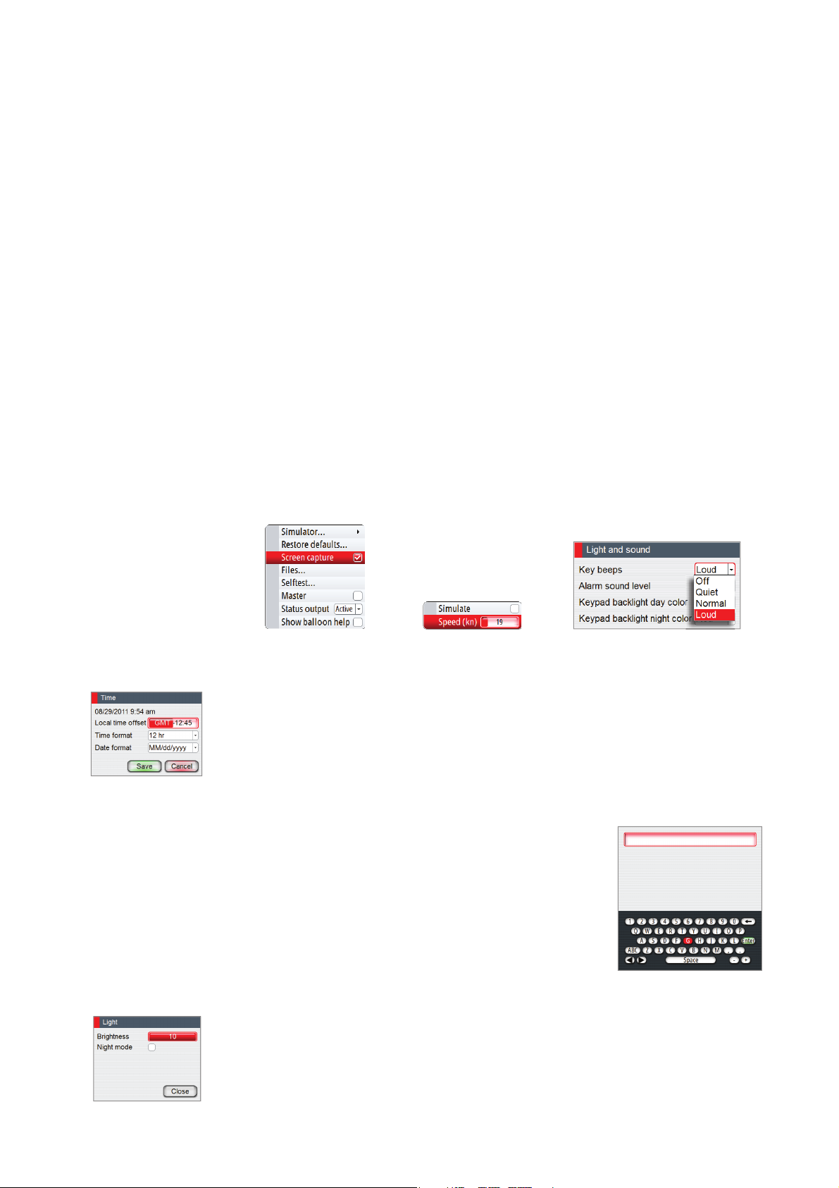
Simulator mode
The autopilot includes a simulator mode useful for demonstration and on show. The simulator
lets you operate the unit without being connected to sensors.
It is not possible to simulate commissioning and setup, but you can adjust simulated vessel
speed.
If the unit is turned off while in simulator mode, this mode will still be active on next power
on.
When the simulator is toggled on this is indicated with a fl ashing message in the lower part of
the display.
Note: Simulator mode is not available if the unit is connected to the CAN bus.
The operational modes | AP70/AP80 Operator Manual
| 27
Page 30

5
W ork pro le setup
A work profi le is a set of steering parameters used by the AP70/AP80 system to improve
the autopilot steering under diff erent operational conditions. This gives high steering
performance very quickly when the operational conditions change, compared to waiting for
the autopilot adaption process.
The AP70/AP80 has a set of predefi ned work profi les. You can edit all predefi ned profi les, and
you can add new profi les. There can be up to 6 work profi les defi ned in the system. All profi les
except Normal can be deleted.
The work profi les are accessed by pressing the Work key. Active profi le is shown in the Mode
status panel.
The Normal pro le
This is the default profi le, and the initial parameters in the profi le are automatically assigned
when you select your vessel type.
During commissioning and seatrial the parameters for active profi le will be tuned for
optimized steering performance. The parameters will be saved as part of the profi le settings.
It is recommended to use the Normal profi le as a general profi le for your vessel. This should
be active during the commissioning of your vessel, and all parameter settings will then be
saved to this profi le.
Creating new pro les
New profi les can be defi ned for operational modes where the vessel’s steering parameters
deviate from the Normal profi le.
You can also defi ne a profi le for easy access to preferred parameters for various crew
members.
1. Press the WORK key to display the work dialog
2. Select the Add button to display the Work profi le dialog
3. Enter profi le name
- The virtual keyboard will be available when the name fi eld is selected
Note: Profi le name is limited to max 6 characters
4. Select a predefi ned work profi le that matches the working conditions
- A new profi le must be based on an existing or a predefi ned work profi le. The parameters
from the work profi le you select as base will be copied to the new profi le, and can later be
edited if required
28 |
Work pro le setup | AP70/AP80 Operator Manual
Page 31

5. Select preferred vessel icon
- Use one of the default vessel icons
6. Enable/disable the work profi le
- Only enabled profi les will be shown in the profi le listing, activated by pressing the WORK
key
7. Edit profi le settings if required
- The default parameters are copied from the profi le you select when creating a new profi le.
These settings can be adjusted to match your preferred steering as described in the next
paragraphs
See also “Importing and exporting work profi les (AP80 only)” on page 32.
Pro le settings
Auto steering
Turn settings
Used for selecting how you want to control the vessel’s turn:
either by defi ning the Rate of Turn (Rate) or the radius.
• Rate range: 5°/minute - 720°/minute
• Radius range: 10 m - 10 NM
- The minimum radius can however never be less than the
value corresponding to a Rate of Turn = 720°/minute at the
set Cruising speed
• Default: Rate
• Initial value: Determined during sea trial
Economy
This allows for higher course deviation before responding, compared to default precision auto
st
ing.
eer
• Range: ON/OFF
• Default: OFF
Wave lter
Automatically reduces the rudder activity and sensitivity of the autopilot in rough weather.
• Ra
nge
: ON/OFF
• Default: OFF
Adaption
This is a software feature that continues to adjust parameters that are essential for the steering
per
f
ormance, e.g. speed, trim, draught and tide eff ects.
When activated these parameters are optimized during the voyage in response to the ship’s
behavior. The settings are stored in the active work profi le.
• Range: ON/OFF
• Default: OFF
Rudder gain
This is the ratio between the heading error and the commanded angle.
• Ra
• Default: Depends on the vessel length
• Initial value: Determined during sea trial
: 0.05 - 4.00
nge
Counter rudder
This parameter counteracts the eff
• Range: 0.05 - 8.00
• Default: Depends on the vessel length
• Initial value: Determined during sea trial
Work pro le setup | AP70/AP80 Operator Manual
t of the vessel turn rate and inertia.
ec
| 29
Page 32

Auto trim
When the vessel has a constant heading error due to external forces such as wind and current,
the Auto trim function corrects for this by building up a constant rudder off set.
The Auto trim value is reset every time the AUTO mode is entered or when a course change
greater than approximately 20° is made.
Auto trim is automatically disabled during a turn.
• Range: 10 - 800 sec
• Default: Depends on the vessel length
O
heading limit
Sets the limit f
An alarm occurs when the actual heading deviates from the set heading more than the
selected limit.
• Range: 5° - 35°
• Default: 10°
Low speed limit
Sets the limit for the low vessel speed alarm.
An alar
• Range: 1 - 20 (kn)
• Default: 1 (kn)
or the off heading alarm.
m occurs when the v
essel’s speed goes below the selected limit.
Track steering
Track response
Defi nes how fast the autopilot shall respond after having registered a
cross track distance.
• Range: 1 - 9
• Default: 4
Track approach angle
Defi nes the angle used when the vessel is approaching a leg.
This setting is used both when y
• Range: 5° - 60°
• Default: 30°
Course change limit
Defi nes the limits for course change to next waypoint in a route. If the course change is more
than this set limit, y
• Rang: OFF / 10° - 90°
• Default: 30°
XTD limit
Defi nes the vessel’s accepted off
limit an alarm will be activated.
• Range: 1 (m) - 1 (NM)
• Default: 50 (m)
e prompted to verify that the upcoming course change is acceptable.
ou ar
ou star
t navigating and when you use track off set.
set distance fr
om the track. If the vessel goes beyond this
30 |
Drive select
Defi nes which drives that shall be used for the selected work profi le.
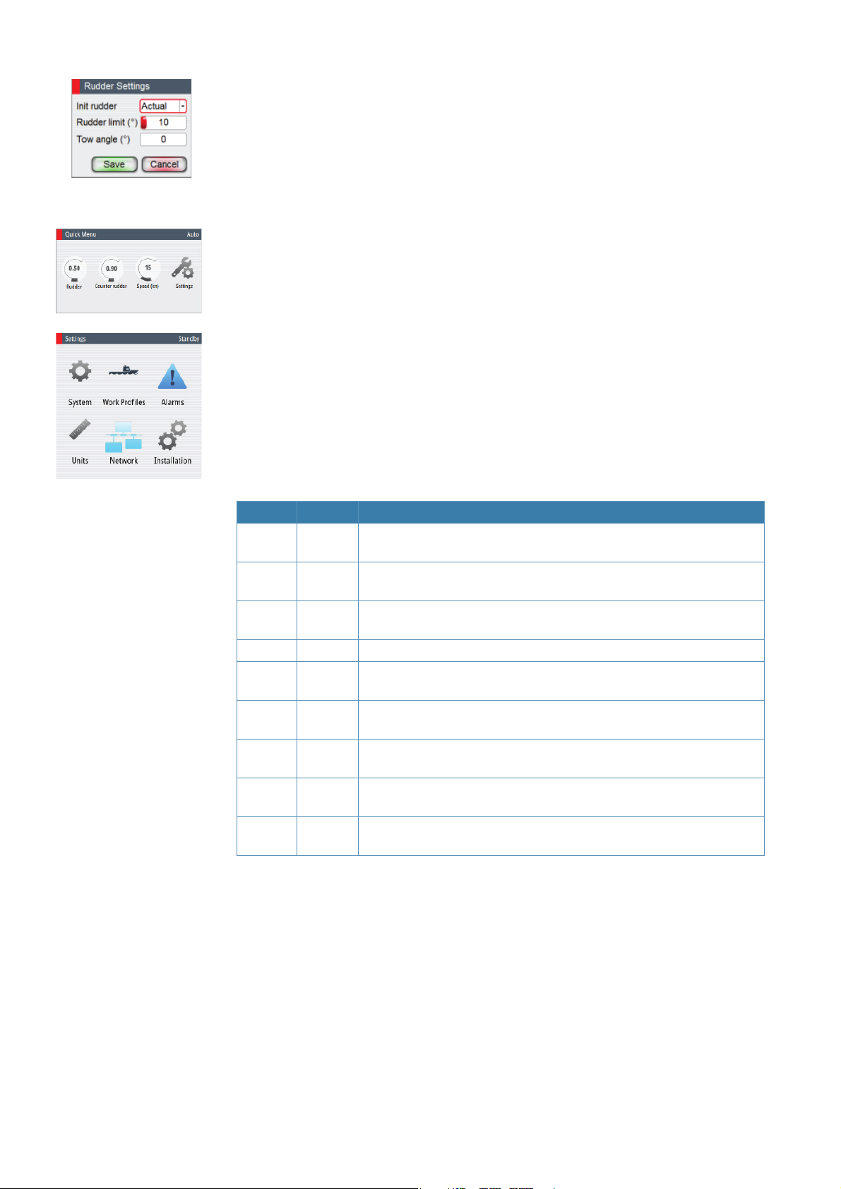
Rudder
Init rudder
Defi nes how the system moves the rudder when switching from power
steering to an automatic mode:
Work pro le setup | AP70/AP80 Operator Manual
Page 33

- Midships moves the rudder to zero position.
- Actual maintains the rudder off set, and use this as trim value (bumpless transfer)
Note: Actual is only available with rudder feedback signal available.
• Default: Midships
Rudder limit
Determines the maximum rudder movement in degrees from the “used” midship position that
the aut
opilot can command the rudder in the aut
“Used” midship position is the rudder angle required to maintain a straight course.
The Rudder limit setting is only active during autosteering on straight courses, NOT during
course changes. This Rudder limit does not aff ect Non-Follow-up or Follow Up steering. In
Non-Follow-up or Follow Up steering, only the max. rudder limit applies.
Note: The max. rudder limit was set automatically to physical stop minus 3° when the rudder
feedback calibration was performed.
• Range: 5° - Max rudder limit
• Default: 10°
Tow angle
Sets the allowed angle deviation between the rudders.
Not
e
: Tow angle is only available if the vessel has 2 rudders.
• Range: In 15° - 0 - Out 15°
• Default: 0°
omatic modes.
Thruster
Thruster sensitivity
Determines how many degrees the vessel must deviate from the set
course before a thruster command is given. As the vessel deviates from its
heading, the thruster will push the vessel back. A higher value will reduce
the thruster activity and extend the lifetime, especially for on/off thrusters.
• Range: 0° - 30°
• Default: 1° for Analog thrusters, 3° for on/off thrusters
Thruster assist
Determines how the thrusters are used by the autopilot.
When set t
speed is below inhibited limit. If the vessel speed is above inhibited thruster speed the
thrusters will be turned off , but will automatically be turned on again when the speed gets
below the inhibited limit.
Note: Thruster inhibit speed is set during installation and is the max vessel speed for which
the thruster is allowed to run.
When set to OFF, thruster has to be manually enabled.
• Range: ON/OFF
• Default: OFF
Push boat to
Allows the user to specify if the trusters should be used to push the vessel to one side only.
I
f no option is selec
deviations.
• Range: ON/OFF for Port and Starboard
• Default: OFF
o ON, the th
ted the thrusters will be used for both port and starboard course
rusters will automatically be used by the autopilot system if the vessel
Work pro le setup | AP70/AP80 Operator Manual
| 31
Page 34

Edit a pro le
You can edit profi le name, icon and settings for all profi les, also for the Normal profi le.
Note: It is not recommended to change any of the auto steering parameters in the Normal
profi le after the vessel is commissioned.
1. Press the WORK key to display all work profi les
2. Turn the rotary knob to select the edit icon on the work profi le you want to change
3. Make the required changes and save the new settings
Note: Refer to “Work profi le setup” on page 28 for details about work profi le settings.
Importing and exporting work pro les (AP80 only)
It is possible to export and import a work profi le to/from a USB stick.
Export
1. Press the WORK key to display all work profi les
2. Turn the rotary knob to select the edit icon on the work profi le you want to export
3. Select Save to disk
- The Files dialog will be displayed
4. Select the USB
5. Press the MENU key and confi rm your selection
32 |
Note: only 6 character can be used to identify the work profi le.
Work pro le setup | AP70/AP80 Operator Manual
Page 35

Import
1. Select Add in the work profi le dialog to create a new profi le
1. Select Load Profi le from disk
- The Files dialog will be displayed
2. Locate the fi le on the USB stick
Note: The work profi le fi les have .wpf extension!
3. Press the LEFT key or the rotary knob to access the fi le details
4. Select Import
5. Confi rm your selection
6. Save the new work profi le
7. Return to the work dialog and confi rm that the imported work profi le is available
Note: The fi rst 6 characters in the fi le name will be used as profi le name.
Work pro le setup | AP70/AP80 Operator Manual
| 33
Page 36

6
The alarm system
The AP70/AP80 system will continuously check for dangerous situations and system faults
while the system is running.
Message types
There are two type of messages:
• Alarms
- Generated when conditions are detected that critically eff ect the capability or
performance of the system.
You must critically examine all alarm messages to determine their course and eff ect.
• Warnings
- Informing you of conditions that could result in unwanted system response or eventual
failure
Alarm indication
When an alarm situation occurs, siren will sound, the alarm icon will be active. The alarm
dialog will show alarm cause, followed by the name of the device that generated the alarm.
Alarm icon
Alarm dialog
Message type Status
Alarm
Warning
The alarm and alarm details are recorded in the alarm listing. Refer “The alarm dialogs” on
page 35.
The icon
The alarm icon will remain on the display until the reason for the alarm/warning is removed.
New
Acknowledged Steady Closed Muted
New
Acknowledges Closed No
Icon
Color Appearance
Red
Yellow Steady
Flashing Yes
Alarm dialog Siren
Until
acknowledged
Yes 2 seconds
34 |
The alarm system | AP70/AP80 Operator Manual
Page 37

The Alarm dialog
All new alarms and warnings activates the alarm dialog. The dialog will be closed when the
message is acknowledged.
If more than one message is activate, this will be indicated in the alarm dialog. Only the cause
for the most recent message will be displayed. The remaining messages are available in the
Alarms listing as described on page 35.
Single active alarm Multiple active alarms
Acknowledging a message
There is no time-out on the alarm message or siren. These remain active until you
acknowledge it or until the reason for the alarm is removed.
The following options are available in the alarm dialog for acknowledging a message:
Option Result
ACK Sets the alarm state to acknowledged, meaning that you are aware of the alarm
condition. The siren will stop and the alarm dialog will be removed.
The alarm icon will however remain active, and the alarm will be included in
the alarm listing until the reason for the alarm has been removed
Mute Mutes the siren locally. The alarm dialog remains on the display
The alarm dialogs
The system includes three diff erent alarm displays:
• Active alarms
- List of all active messages
• Alarm history
- Alarm events, including alarm type and time/date
• Alarm settings
- List of all alarms that can be enabled and confi gured by the user
The alarm system | AP70/AP80 Operator Manual
| 35
Page 38

Setting the alarm and warning limits
The alarms and warning limits are adjusted from the settings display.
1. Activate the alarm settings dialog as shown above
2. Select the parameter to be changed
3. Press the rotary knob to edit the value
4. Change the value by using the rotary knob or the arrow keys
5. Repress the rotary knob to confi rm your setting
Only a few alarms can be turned off . These are indicated with a check box, and are turned on/
off by pressing the rotary knob.
Note: Additional alarm limits that can be defi ned for each Work profi le. Refer to Work Profi le
description in the Operator Manual.
Compass di erence limit
When two compasses are used (main compass and monitor compass), there is virtually
always a diff erence between the readings of the two. If the diff erence exceeds the set limit, an
alarm is given.
Note: The diff erence between the two compass readings may vary with the vessel’s heading
and from one area to another where a vessel is in transit. The diff erence between the two
compass readings is automatically reset when a Compass diff . alarm is acknowledged.
• Range: 5° - 35°
• Default: 10°
Course di erence limit
Sets the value the actual heading can diff er from track course.
• Range: 5° - 35°
• Default: 35°
Sharp turn limit
Gives a warning if a turn is started in any auto mode with a combination of speed and turn
rate/radius that will cause sidewise acceleration bigger than set limit.
• Range: OFF / 1 - 10 m/s
• Default: OFF
Fallback and failures during automatic steering
Rudder angle sensor missing
Alarm will be given and steering will after 0.1 sec continue using “virtual” rudder angle data
(virtual is estimated value based on known rudder speed)
Steering compass missing
When monitor compass is available
Alarm for main compass failure is given and steering continues using monitor compass. If
there is a diff erence between the compasses, a smooth transition (2 min fi lter) to the monitor
compass heading takes place.
When acknowledging the alarm, the autopilot goes to STBY mode.
36 |
When no monitor compass
Rudder is kept at fi xed angle (i.e. heading is approximately maintained if failing when heading
keeping, turn is approximately maintained if failing when turning), alarm is given and
autopilot goes to STBY mode.
The alarm system | AP70/AP80 Operator Manual
Page 39

Magnetic variation missing
If heading source is set to be adjusted for magnetic variation, variation is taken from available
sensors in following order: Position source – Navigation source – Compass – any other
variation available on CAN bus. If variation disappears, last valid variation will be used until
automatic steering is cancelled and heading shown will then be corrected according to
alternative variation in the order given above.
Jump in heading data
If there is an abnormal heading jump in steering compass heading, an alarm will be given and
a smooth transition to new heading will take place. There may also be a compass diff erence
alarm if a monitor compass is in use.
Speed sensor lost
If speed in use is lost there will be an alarm and smooth transition (2 min fi lter) to fallback
speed. Speed for steering and speed for navigation will use following use priority and fallback:
Steering: STW STW backup SOG SOG backup Manual speed Cursing speed
Navigation: SOG SOG backup STW STW backup Manual speed Cruising speed
Position data missing
During NoDrift steering, alarm is given and a smooth transition to position backup source
takes place. If no position backup steering source, steering mode will change to auto heading.
Navigation data missing
If lost during track/nav. steering, give alarm and change to auto heading steering.
Local supply voltage missing
When control unit(s) and CAN bus have diff erent power source, alarm will be given on active
control unit with sound and fl ashing red power button led (display will go “black”). Main
steering computer will go to STBY mode and activate alarm on all other control units.
CAN bus supply voltage missing
Active control unit will give local alarm and rudder/thruster drive units will go to STBY mode.
Rudder/thruster drive computer failure
Alarm will be given and the ready signal to the steering /thruster gear will disappears. If sw
failure, there will be a watchdog restart of failing drive computer. The autopilot steering
computer will try to maintain steering as far as possible with remaining drive computers.
If the faulty unit is the autopilot steering computer, autopilot backup computer has to be
selected manually (ref. Menu- source selection).
List of possible alarms and corrective actions
The next pages includes a list of all alarms generated by the autopilot system.
The AP70/AP80 control units might also display alarms received from other units connected
to the system. Refer separate documentation for the relevant equipment for further
descriptions of these alarms.
The alarm system | AP70/AP80 Operator Manual
| 37
Page 40

Alarm/Warning Type Warning/Alarm condition Possible cause and recommended action
Red fl ashing AP70/
AP80 power button,
black display
Active control unit
missing
Autopilot computer
missing
Boat speed missing W/A Lost sensor data
CAN bus failure A
CAN bus supply
overload
Check heading A
Compass diff erence A
Course diff erence A
Cross track distance
limit
Drive inhibit A
A < 5 V
Autopilot computer has lost
A
contact with active control
unit
Active control unit has
A
lost contact with autopilot
computer
Not possible to send or
receive data although bus
voltage is ok
W Current >4.3 A Check summary unit loads
Current >10 A for 1 ms, hw
A
shutdown
Lasting steering compass
heading jump >10° within 1
sec during automatic steering
Diff erence between steering
compass and monitor
compass +variance > set limit
Actual heading diff from track
course by set limit
W/A XTD > XTD limit
Motor or solenoid drive
electronics critically
overloaded
Local supply voltage to AP70/AP80 missing or <5 V.
Check local supply, connections and fuses to AP70/AP80
control units
Active control unit goes silent.
1. Check/repair CAN bus cable
2. Replace the control unit
Faulty autopilot computer or poor cable connections from
the same.
1. Check connectors and cable
2. Check local power to control unit
3. Check that control unit is turned on
4. Replace autopilot computer
Note: This alarm will only show up on passive units
if active control unit is defective or has lost bus
communication.
The speed signal from the GPS or the log is missing.
1. Check Device list for valid speed source
2. Try a new automatic source update
3. Check the GPS, log, and cable connections
Poor CAN bus backbone, defective cable/connector or
defective CAN bus receiver in autopilot control unit.
1. Check backbone terminations
2. Check cable and connectors
3. Replace Autopilot control unit
Excessive current draw.
Check for short circuit/defective device on network.
A sudden jump in heading of more than 10 degrees is
detected
Check steering compass. Possibly change to other heading
source or monitor compass.
The diff erence in readings between the main compass and
the monitor compass exceeds the limit set for “Compass
diff erence”.
Check the operation of both compasses. If one compass is
magnetic, the error may be caused by deviation change or
heavy sea disturbances.
Compass heading is deviating too much from the track
course (BWW). May be caused by extreme wind and
current, combined with low speed.
XTD has reached set XTD limit in NAV/TRACK mode. May
be caused by extreme wind and current or too low boat
speed.
Check f
wires.
e shortage, eventually disconnect suspicious
or wir
38 |
The alarm system | AP70/AP80 Operator Manual
Page 41

Alarm/Warning Type Warning/Alarm condition Possible cause and recommended action
Check that steering gear/thruster is set for autopilot
No drive available response
Drive not available A
Drive reference
voltage missing
Drive unit failure W/A
End of route A
ENGAGE output
overload
EVC comm. error A
External mode illegal A
igh internal temp. W >75°C Excessive temperature in unit (>75°C).
H
High drive temp.
Low CAN bus
voltage
Low supply voltage W <10 V (12 V -15%)
Low boat speed W/A
Monitor compass
missing
upon request from autopilot
on Handshake port of faulty
SD80/AD80 board
Reference voltage to faulty
A
AD80 is missing
Autopilot computer has lost
communication with faulty
device
Given if WP name = "End of
route"
W Current > 3.5 A Bypass valve or clutch is drawing excessive current (>3,5 A).
A Current > 5 A
Lost communication with EVC
system (Volvo IPS and similar).
Signals to external mode
input port of faulty SD80/
AD80 board has illegal
combination
Drive electronic temperature
W
>80°C
Drive electronic temperature
A
close to critical for more than
1 s.
W < 9 V
Speed below set limit for
steering in Work profi le
W Lost sensor data
control.
Check cabling to Handshake port of faulty SD80/AD80
board.
Make sure Handshake port of faulty SD80/AD80 board is
confi guration for HS fi xed/HS pulse (refer “Confi guring the
handshake” on page 44.
Check that the two U_CTRL dip switches of faulty AD80
boar
d is set cor
faulty unit).
If drive control signal is 4-20 mA current or voltage using
internal ±10 V reference, switches must be set to INT. If
ext
ernal ref. voltage is connected switches must be set to
EXT.
If ext. ref. voltage, check cabling and measure correct
voltage bet
Check that green CPU led of faulty unit is alternating (ref.
label inside unit cover for location of led). If off , check local
power supply/fuse (AC70). For other boards, check CAN
supply for 9-15 V between NETS and NETC of SimNet
plug. If led is ok, check cabling, T-connector backbone etc.
If led is on, try to restart unit by turning power off /on
Warning given on the active control unit when a “END
ROUTE” waypoint name has been received from the
Plotter/ECS.
Make sure there is no shortage to ground or cabling
damage, disconnect cable from AC70 to motor, and make
sure there is no alarm when engaging FU or Auto mode.
Check connection with EVC engine interface.
For IPS, engine must be running.
Check if alarm is given for a certain position of external
mode selector. Check cabling to MODE SEL port of faulty
boar
d
Excessive temperature in Autopilot Computer drive
transistors (>80°C), possible long term overload.
1. Switch off autopilot
2. Check for backload in Drive unit/steering system.
3. Check that the autopilot computer specifi cations
matches Drive unit
Check cable length, bus load and bus supply feeding point.
If possible, check if fault disappears by disconnecting some
units
Mains voltage less than 10 Volts.
1. Check battery/charger condition
2. Verify mains cable has correct gauge
Speed below set limit for acceptable course keeping (in
Work profi le). Switch to hand steering or adjust Work profi le
settings.
No data from the selected monitor compass. (Warning
only.)
rectly (ref. cable connection label inside
ween U_REF+ and U_REF of AD80 board
The alarm system | AP70/AP80 Operator Manual
| 39
Page 42

Alarm/Warning Type Warning/Alarm condition Possible cause and recommended action
Navigation data from Plotter/ECS is missing.
Navigation data
missing
New WP A
No rudder response A
Off heading A
Override W
Position data missing W/A
Rudder data missing A
Rudder limit W
Rudder too slow W
Sharp turn W
W/A
Lost sensor data
(NAV mode)
Ref. "Course change confi rm
limit" in NAV
No response to rudder
command
Boats heading is outside set
off heading limit. Automatic
reset when inside limit
1. EVC override via SG05
2. Override via SD80/AD80
Handshake (ref. KaMeWa)
3. Override via SD80/AD80
RUD UI port
Lost sensor data
(NoDrift mode)
Rudder angle signal to faulty
board is missing
Limit rel. to rudder cmd in
auto modes. Not applicable
for NFU/FU where rudder
shall stop at max -3°
Rudder speed from RF < 2°/
sec
Acceleration > set g-limit
(Alarms - settings)
1. Check Device list for valid navigation source
2. Try a new automatic source update
3. Check the Plotter/ECS and cable connections
Nav mode only; Course change from one leg to the next is
exceeding set "Course change limit"
1. Check all connections
2. Check Rudder FB transmission link (not applicable for
Virtual feedback installations)
3. Check drive unit motor/brushes
4. For SD80, check that port/stbd led is activated (ref label
in cover for location
5. Replace the Autopilot Computer Drive board
May be caused by extreme weather conditions, and/or too
slow speed.
1. Check steering parameters (Rudder, Autotrim, Seastate-
fi l t e r )
2. Increase Response/Rudder value
3. Increase boat speed, if possible, or steer by hand
If unintended warning, make sure override handle is
not being activated by loose objects. Check cabling and
override switches connected to Handshake port of faulty
SD80 or AD80 board
Position data from the GPS is missing.
1. Check Device list for valid position source
2. Try a new automatic source update
3. Check the GPS and cable connections
If several rudder angle sensors, check which one the faulty
board is set up for use (refer “Drive test/calibration” on page
46). If the missing sensor is connected to an autopilot
computer check cabling to the board. If missing sensor is a
CAN device, check backbone bus network connection.
The set rudder limit has been reached or exceeded. This
is a warning only and may be caused by disturbance
to compass (waves), speed log, sharp turn or improper
parameter setting.
Excessive load on steering gear. Air in hydraulic system.
Insuffi cient drive unit capacity.
1. Look for mechanical obstructions at the rudder/tiller/
quadrant. Check the back drive force
2. Bleed the hydraulic system
3. Replace with bigger pump unit
If unintended warning, check that the boat speed to the
autopilot is correct. Check that set turn rate or radius
corresponds to actual
40 |
The alarm system | AP70/AP80 Operator Manual
Page 43

Alarm/Warning Type Warning/Alarm condition Possible cause and recommended action
AC70: Motor/sol current >
30 A
W
SD80: Sol current >8 A
Drive overload
AC70: Mot/sol current > 55 A
A
SD80: Sol current > 9 A
Steering compass
missing
Thruster inhibited W Vessel speed > set limit
A Lost sensor data
Reversible motor
Motor stalls or is overloaded
4. Fix possible mechanical blocking of rudder.
5. If heavy sea at high rudder angle, try to reduce boat
speed or rudder angle by steering at another heading
6. Make sure there is no shortage to ground or cabling
damage, disconnect cable from AC70 to motor, and
make sure there is no alarm when trying to run NFUmode
Solenoids
Shortage to ground or cabling damage. Same action as for
motor
No data from the selected steering compass. If no monitor
(back up) compass; the autopilot goes to STBY mode.
If Monitor compass; the autopilot switches to monitor
compass. If there is a diff erence the autopilot will gradually
synchronize with the new heading (2 minutes).
The vessel speed exceed the set limit for when thrusters
can be used.
Note: The Thruster inhibit limit will only apply when
speed source is Log or SOG, not if the speed is set
manually.
The alarm system | AP70/AP80 Operator Manual
| 41
Page 44

7
Maintenance
Preventive maintenance
The AP70/AP80 control units do not contain any fi eld serviceable components, therefore the
operator is required to perform only a very limited amount of preventative maintenance.
To prevent UV damage to the plastic bezel and rubber keys, it is recommended that the sun
cover (option) be fi tted when the unit is not in use for an extended period.
Simple maintenance procedures
Cleaning the display unit
The supplied cleaning cloth should be used to clean the screen where possible. Use plenty of
water to resolve and remove salt remains. Crystallized salt may scratch the coating if using a
damp cloth. Apply minimal pressure to the screen.
Where marks on the screen can’t be removed by the cloth alone, use a 50/50 mixture of warm
water and isopropyl alcohol to clean the screen. Avoid any contact with solvents (acetone,
mineral turpentine etc.), or ammonia based cleaning products, as they may damage the antiglare layer, plastics bezel, or rubber keys.
Checking the connectors
The connectors and computer terminals should be checked by visual inspection only.
Push the connector plugs into the connector. If the connector plugs are equipped with a lock;
ensure that this is in the correct position.
Restoring factory default settings
A default restore will reset the memories to factory settings.
The fi rst time the autopilot system is started and after restore, it will run through the
automatic setup-procedure.
Note: Unless you need to clear all stored values during the installation set-up procedure, you
should not perform a restore of factory settings.
42 |
Maintenance | AP70/AP80 Operator Manual
Page 45

STBY AUTO NAV WORK
Software upgrades
The latest software for the AP70/AP80 will be available for download from our web sites:
pro.simrad-yachting.com and www.simrad-yachting.com.
Detailed instructions for how to install the software will follow the upgrade fi les.
Backing up your system data
It is recommended to copy the user settings fi les after the
system has been commissioned. This should also be done as
part of your back-up routine.
See the next section describing how to manage fi les in the
autopilot control units.
File management
The autopilot includes a fi le management system. For AP80 fi les can be copied to a USB stick
inserted in the card slot on the front of the unit.
The following procedure describes how to copy your settings database to a USB stick.
1. Press the MENU key twice to access the Settings dialog, and continue as illustrated to access
the Files dialog
MENUCMD
3
TURN
2. Select the Settings database folder
3. Press the MENU key, and select Export
4. Select the USB stick
ALARM
5. Press the MENU key again, and confi rm your selection
ALARM
Maintenance | AP70/AP80 Operator Manual
| 43
Page 46

8
Menu overview
The Quick menus
The Quick menus are mode dependant, displayed by pressing the MENU key.
The menus containing the most common used settings for the active mode. Each Quick
menu have access to the Settings menus.
The Quick menus are described in the “The operational modes” on page 17.
Quick menu in Manual modes
From the Quick menu for STBY, NFU and FU you can change sources used for steering, you
can display active alarms and set manual speed.
LEVEL 1 LEVEL 2 LEVEL 3 LEVEL 4
Sources
Alarms
Speed (Adjust)
Settings
Auto Select
Steering compass
Monitor compass
Navigation
Position
Position backup
Boat speed
Boat speed backup
Depth
Apparent wind
Calculated wind
Pilot computer
Pilot computer backup
(List of active alarms)
(Settings dialog/menus)
Group
Advanced
nnn
Simrad / None
Data Source
Selection
Quick menu in Automatic and navigational modes
Steering performance in automatic and navigational modes might be adjusted from the
mode’s Quick menu.
The diff erent settings are described in “Controlling steering performance in automatic and
navigational modes” on page 28.
44 |
Auto mode
LEVEL 1
Rudder (Adj.)
Ctr.rudder (Adj.)
Speed (Adj.)
Settings
Menu overview | AP70/AP80 Operator Manual
(Settings dialog/menus)
Page 47

NoDrift and NAV mode
LEVEL 1
Track resp (Adj.)
Rudder (Adj.)
Ctr.rudder (Adj.)
Speed (Adj.)
Settings
The settings dialog and submenus
(Settings dialog/menus)
The system is confi gured and most system settings
defi ned during installation and commissioning of the
system.
All system confi guration and Installation setup is
described in the separate AP70/AP80 Installation
manual.
The settings parameters are logically grouped, and
each group is presented with an icon in the Settings
dialog. This dialog is accessed by pressing the Settings
icon available in all mode specifi c menus, or by double
clicking the MENU key.
LEVEL 1 LEVEL 2 LEVEL 3
System
Work proles
Alarms
Units (select)
Network
Installation
Language (select)
Light and sound
Time
Advanced
About
(Create/Edit/
Enable)
Key beeps
Alarm sound level
Keyp. backl. day
Keyp. backl. night
Local time oset
Time format
Date format
Simulator
Active
History
Settings
Restore defaults
Screen capture
Files
Selftest
Sources
Device list
Diagnostics
Master
Status output
Show balloon help
SimNet groups
Damping
Dockside drives
Dockside boat
Compass calibr.
Seatrial drives
Seatrial boat
Menu overview | AP70/AP80 Operator Manual
| 45
Page 48

System
Advanced system settings
Work pro les
User settings that have not any aff ect on autopilot
performance.
Used for creating and managing the vessel’s work profi les.
Described in “Work profi le setup” on page 30.
Alarms
Units
Network
Alarm listings and settings.
Described in “The Alarm dialog” on page 35.
Units of measure used on display, in dialogs and menus.
List of devices connected to the CAN bus network.
Used for setup, diagnostics and confi guration.
See “System confi guration” on page 47.
46 |
Installation
Includes dockside and seatrial calibrations.
See “System confi guration” on page 47.
Menu overview | AP70/AP80 Operator Manual
Page 49

9
System con guration
General
When the autopilot installation is completed, the system must be confi gured and the
commissioning procedures performed. Failure in setting up the autopilot correctly may
prohibit the autopilot from functioning properly.
The settings dialog and submenus
The system confi guration settings are logically grouped in the Settings dialog, and each
group is presented with an icon. This dialog is accessed by pressing the Settings icon available
in all mode specifi c menus, or by double clicking the MENU key.
Icon Description Refer
System settings. These settings have no aff ect
on autopilot performance
Work profi le settings
Active alarms, alarm history and alarm
settings
Units of measure used on display, in dialogs
and menus.
Network sources setup
Installation setup.
The pilot must be in Standby mode to access
these settings
AP70/AP80 Operator
manual
-
“Network settings” on page
48
“Installation settings” on
page 52
Turning on for the rst time
Before attempting to turn on the autopilot and perform an Installation Set-up, the hardware
installation and electrical installation must be completed and performed in accordance with
the installation instructions
The fi rst time the autopilot system is started and after a factory reset, you will be guided
through a set of initial settings.
If the settings are not completed, you can confi gure the autopilot system manually as
described in the following sections.
System con guration | AP70/AP80 Operator Manual
| 47
Page 50

Network settings
Setup and selection of sources are done from the Network menu.
Selecting data sources
A data source can be a sensor or a device connected to the network, providing data to other
devices. Data can be of diff erent type such as compass data, apparent wind data, calculated
wind data, depth data, etc.
Source selection is required on initial start up of the system, if any part of the CAN bus
network has been changed or replaced, or if an alternative source is made available for a
given data type and this source has not been selected automatically.
At the fi rst time turn on of a group of SimNet interconnected products, data sources are
automatically selected from an internal SimNet priority list. If a data source is connected to
SimNet after the fi rst time turn on, this will be identifi ed and automatically selected if no other
data source already is selected for the given data type.
You can let the system automatically select your sources, or set up each source manually as
described below.
Auto select
The Auto Select option will look for all SimNet sources connected to the network. If more
than one source is available for each data type, the system will automatically select from an
internal priority list.
The Auto select function is mainly for situations where the automatic source selection needs
to be updated because a selected data source is not supplying data or has been physically
replaced with another one. The update secures that the existing source selections are valid
and maintained. Missing sources are either automatically exchanged with an alternative
source from the list of available sources for the given data type, or the replacing source is
selected.
Manual source selection
You can manually select the preferred source. This is useful if you have more than one of the
same type of device on the network.
Available sources are listed as shown in the example below. You select active source by
ticking the preferred unit.
Group selection
The autopilot system can use data sources that all other products on the network use, or
select individual sources for the autopilot system.
If the group is set to Simrad, any changes to a source will also aff ect other systems on the
network.
If the group is None, the selected source will be used for the autopilot system only.
In the example below the steering compass is common for all systems on the network.
48 |
Advanced selection
Allows the advanced selection of sources available on the network.
System con guration | AP70/AP80 Operator Manual
Page 51

Device list
From the device list you can:
- list all of the active SimNet and NMEA 2000 devices on the network, showing model
description and serial number. Devices can be sorted by model ID or by serial number
- display information relating to a device such as, name, manufacturer, software version,
instance, status
- give the device a logical name relevant to the user
- see data coming from the device
- get access to confi guration page for the device
• Press the MENU key to sort the device list
• P
r
ess the MENU key, the STBD key or the rotary knob to see selected device details.
Note: The graphics show gyro input on an SI80 board. Device details and options depends on
data type.
Diagnostics
The diagnostic page shows details for the NMEA 2000/CAN bus network.
System con guration | AP70/AP80 Operator Manual
| 49
Page 52

Option Description
Bus State
Rx Overfl ows
Rx Overruns
Indicates if network backbone is operating. Check power: Check
termination
Value greater than 0 could indicate the software is very busy and
unable to keep up with incoming messages.
Rx Errors CAN interface error counters. Count up when there are errors on
the CAN bus, and down when things are ok. Should normally be
Tx Errors
0. Goes bus off when 255 is reached. Check same things as for Bus
state if greater than 0 observed
Fast packet Errors:
Rx Messages
Tx Messages
Detected errors since power up. Check the network if this is
continually increasing.
A count since power up of messages received / transmitted.
Bus Load Real time bus load in percentage of max capacity
SimNet groups
The SimNet Group function is used to control parameter settings, either globally or in groups
of units. The function is used on larger vessels where several SimNet units are connected via
the network. By assigning several units to the same group, a parameter update on one unit
will have the same eff ect on the rest of the group members.
The illustration below shows a two station installation. Units on the bridge have their
backlight and damping settings in diff erent SimNet Groups from the units in the cockpit.
If the back light is adjusted on a display in the cockpit, it will change on all displays in the
cockpit. It will not change the light settings on the bridge. If the damping is adjusted on the
AP80 control unit, this will also aff ect damping on the NSE unit in the remote station.
MAIN BRIDGE
REMOTE STATION
QS80
AP80 CONTROL HEADNF80
STBY AUTO NAV WORK
NSE
MENUCMD
3
TURN
ALARM
50 |
System con guration | AP70/AP80 Operator Manual
Page 53

Master systems
The international standard for heading control systems (ISO 11674/ISO 16329) requires
controlled command transfer when remote stations are provided. The delegation of control to
the remote station and the return of control shall be incorporated in the autopilot system, and
shall avoid unintended operation from a remote station.
To fulfi ll this requirement the AP70/AP80 system includes a Master function. This is used in
larger Wheelmarked systems where you permanently want to control command transfer to
remote stations.
In a Master system, one steering station is defi ned as the Master station. There can be several
control units in a master station, but only one of them can be set as the Master unit.
All units included in the master station will be unlocked, and command transfer within the
master group will be as in an open system.
Units not included in the master station will be locked. It is not possible to take command
from units outside the master station unless the master control unit opens for this. All units
outside the master station will have a lock symbol.
In the illustration below the main bridge is defi ned as master station. One QS80, one AP80
control unit and one AP70 control unit are included in the master station. The AP80 control
unit is defi ned as the Master unit.
The illustration includes SimNet group settings for each unit, showing how the units are
defi ned as part of diff erent SimNet stations.
MAIN BRIDGE
3 3
AFT STATION
3
De ning a Master system
WING STATION
A master station is usually defi ned and units assigned to the master station during system
setup.
Note: When a SimNet group Station is set to Master, one control unit in this steering station
has to be defi ned as the Master unit as shown below.
System con guration | AP70/AP80 Operator Manual
| 51
Page 54

Damping
Controls how quickly the display updates values from sensors.
Increasing the damping applies more averaging or smoothing of the data update rate on the
display.
Damping settings are applied to SimNet units belonging to particular damping SimNet
Groups.
Note: If the damping factor for heading is high, the captured heading might diff er from the
heading read on the display when using the heading capture function.
Installation settings
The installation setup includes dockside and seatrial confi guration of drives, together with
compass calibration.
When the autopilot is delivered from factory AND ANY TIME AFTER AN AUTOPILOT RESET HAS
BEEN PERFORMED, the installation settings are all reset to factory preset (default) values. A
notifi cation will be displayed, and a complete setup has to be made.
Note: The Installation settings can only be accessed in STBY mode.
Warning: The installation settings must be performed as part of the
commissioning of the autopilot system. Failure to do so correctly may
prohibit the autopilot from functioning properly!
Note: The seatrial settings are dependent on successful completion of the dockside settings.
Dockside - Drive system
Drive units must be confi gured and calibrated before they can be used.
The drive system confi guration dialog lists all drive units available on the network. The details
fi eld includes drive type, serial number and source name.
When the drive confi guration is completed this is indicated with a tick after the drive name.
The dialog will not illustrate drive type and location before the drive location and type is
defi ned.
52 |
System con guration | AP70/AP80 Operator Manual
Page 55

The following symbols are used to illustrate drive type:
Tunnel thruster
Azimuth
Voith Schneider
Rudder
WaterJet
The fi gure shows a completed commissioning for a vessel with one rudder driven by an SD80
board, one solenoid operated tunnel thruster and one analog tunnel thruster operated by
two diff erent AD80 boards.
Con guring the drive system
The drive system confi guration is accessed from the drive system confi guration dialog.
1. Select the drive to be confi gured, and press the rotary knob or the MENU key to proceed to
the device
information dialog
2. Enter a descriptive name for the device (e.g. Aft thruster)
- If two identical boards are used, they are identifi ed by the serial number. This number is
found in the device information dialog on a tag on the SimNet plug on the board
Note: The label below is an example only and varies with board type.
AD80
System con guration | AP70/AP80 Operator Manual
AD80
| 53
Page 56

3. Select the Confi gure option to proceed to device confi guration dialog. The dialog diff ers
slightly for the diff erent drive types
4. Select relevant settings for the selected drive, and save your settings
Con guring the handshake
54 |
Handshake settings
Handshake
Function Description
setting
HS fi xed Autopilot/steering gear
interface with fi xed
level signals
HS pulse Autopilot/steering gear
interface with pulse
signals
System con guration | AP70/AP80 Operator Manual
Output contact is closed when autopilot
requests steering gear control.
Input to be closed as long as steering gear is
available for autopilot control
Output contact is closed for 1 sec when
autopilot requests steering gear control.
Input to be closed as long as steering gear is
available for autopilot control
Page 57

Handshake
setting
Override Dodge Manual override with
Override STBY Manual override to
Override ext FU Unconditional external
Function Description
fallback to AUTO
STBY
FU/DP control
When input contact is closed, autopilot will
give override warning, acknowledge with
closed output contact and go to STBY mode.
When input opens, output contact will open
and autopilot returns to AUTO mode on
present heading. Typically used for joystick
hand steering with override button on top.
Note: must be limited to one autopilot
computer board
When input contact is closed, autopilot will
give override warning, acknowledge with
closed output contact and lock to STBY
mode. When input opens, output contact
will open and autopilot will unlock. This
function is normally related to regulations for
automatic override when main hand steering
is operated.
Note: Must be limited to one autopilot
computer board
When input contact is closed, autopilot will
respond with closed output, display “External”
and use the installed current or voltage input
to the RUD UI plug of SD80/AD80 board for
f
ollow up rudder contr
ol.
Note: Must be limited to one autopilot
computer board
FU-remote External FU/DP control
by command transfer
Alarm panel Interface to central
alarm panel with direct
I/O
P-log & Auto Pulse log input, auto
mode output
Pendulum & WA If input signal is closed, steering and monitor
When input contact is closed, a command
transfer dialogue is started (refer Command
transfer description in the AP70/AP80
Operator Manual). When accepted, the output
contact will close and use the installed current
or voltage input to the RUD UI plug of SD80/
AD80 board f
Output will open if control is taken from
another unit again.
Refer “Central alarm panel with direct I/O
interface” on page 33.
If a pulse log of 200 p/NM to the input, it
will show up as a speed source on the CAN
network.
The output will be a closed contact whenever
the autopilot is in AUTO, NoDrift or NAV/
TRACK mode. The signal can be used for
reducing oil fl ow to rudder, watch alarm
activate etc.
compass will be off set by 180°.
Output contact will close for 0.5 sec when
active control unit is operated. Can be
used for watch alarm systems that require
information about operation of equipment.
or follow up rudder control.
System con guration | AP70/AP80 Operator Manual
| 55
Page 58

Rudder feedback/tunnel thruster feedback calibration
If a rudder or thruster feedback is available, this must be calibrated. This is required for the
autopilot to know signal for mid-position, port/starboard side and rudder movement range.
Note: The graphics below shows the dialog when the rudder is controlled by an SD80. The
confi guration dialog varies with drive device and drive type.
1. Select feedback calibration option in the device confi guration dialog
2. Follow the guided steps through the calibration process
3. Save the settings when completed
Drive test/calibration
When the drives are confi gured and calibrated, the autopilot need to know drive output level
for standstill, polarity for port/stbd movement, the speed/signal- level relationship and max
signal levels allowed. This is learned during the drive test or drive calibration.
1. Select test option in the device confi guration dialog
56 |
2. Follow the guided steps through the testing process
3. Save the settings when completed
Note: When a rudder feedback signal is set in the confi gure view, the feedback must always
be calibrated before drive test or drive calibration is allowed.
Vessel con guration
Note: The unit of measurement in the dialog refl ects your unit settings.
Boat type
The boat type setting is used by the system to select appropriate preset steering parameters.
It will also aff ect available autopilot features.
System con guration | AP70/AP80 Operator Manual
Page 59

Boat length
The boat length aff ects the steering parameters.
• Rang: 5 - 500 (m)
Cruising speed
The cruising speed is used if no speed info is available, and if manual speed is set to Auto.
It is also used by the autopilot system to calculate steering parameters.
• Rang: 2 - 50 (kn)
• Default: 15 (kn)
Transition speed
Note: Only available if the boat type is set to planing.
The transition speed is the speed at which the system automatically changes from LOW to
HIGH work profi le.
These two work profi les are automatically defi ned when you set the boat profi le to planing.
The work profi les are set up with high and low speed parameters to control the diff erent
steering characteristics before and after planing.
On power boats it is recommended that you set a value that represents the speed where the
hull begins to plane or the speed where you change from slow to cruising speed.
HI work profi le
Transition to HI work profi le with
LO work profi le
increasing speed: 10 kn
Transition speed set to 9 kn
Transition to LO work profi le
with decreasing speed: 8 kn
• Rang: OFF - 40 (kn)
• Default: OFF
Thruster inhibit speed
This feature will block the thruster from running above a set vessel speed. It is a safety feature
to prevent, especially electrical on/off thrusters, from overheating if out of water or for
instance a planing boat or in rough weather.
When the speed exceed the set limit the truster indication will change as shown below.
Thruster(s) in use Thrusters unavailable when
System con guration | AP70/AP80 Operator Manual
speed exceed inhibit limit
| 57
Page 60

Note: The Thruster inhibit limit will only apply when speed source is Log or SOG, not if the
speed is set manually.
• Rang: 1 - 40 (kn)
• Default: 6 (kn)
Low speed limit
Sets the limit for the low vessel speed alarm.
An alarm occurs when the vessel’s speed goes below the selected limit.
• Range: 1 - 20 (kn)
• Default: 1 (kn)
Init rudder
Defi nes how the system moves the rudder when switching from power steering to an
automatic mode:
- Midships moves the rudder to zero position.
- Actual maintains the rudder off set, and use this as trim value (bumpless transfer)
Note: Actual is only available with rudder feedback signal available.
• Default: Midships
Seatrials
Compass calibration
All magnetic compasses must be calibrated as part of the autopilot seatrial procedure.
Before the compass calibration is started, make sure that there is enough open water around
the vessel to make a full turn.
The calibration should be done in calm sea conditions and with minimal wind to obtain good
results. Follow the on-screen instruction, and use about 60-90 seconds to make a full circle.
1. Start the calibration by selecting the Calibrate button in the device calibration dialog
2. Follow the online instructions
During the calibration, the compass will measure the magnitude and direction of the local
magnetic fi eld.
• If the local magnetic fi eld is stronger than the earth’s magnetic fi eld (the local fi eld is reading
more than 100%), the compass calibration will fail
• If the local fi eld is reading more than 30%, you should look for any interfering magnetic
objects and remove them, or you should move the compass to a diff erent location. The (local)
fi eld angle will guide you to the local interfering magnetic object.
Lubber line
20%
Magnitude of local eld in % of
ear
’s magnetic eld.
th
58 |
Direction of local eld with respect
10°
to lubber line. It can also be on the
reciprocal.
Note: Calibration must be made on the compass that is active for the autopilot. If another
model compass from Simrad or another manufacturer is installed, refer to the calibration
instruction for that compass.
Note: In certain areas and at high latitudes the local magnetic interference becomes more
signifi cant and heading errors exceeding ±3° may have to be accepted.
System con guration | AP70/AP80 Operator Manual
Page 61

Compass mounting o set
The diff erence between the compass lubber line and the boat’s center line should be
compensated for.
1. Find the bearing from the boat position to a visible object. Use a chart or a chart plotter
2. Steer the boat so that the center line of the boat is aligned with the bearing line pointing
towards the object
3. Activate the device confi guration dialog as shown below
- Ensure that the active compass is selected
4. Change the off set parameter so that the bearing to the object and the compass readout
becomes equal
Note: Make sure that both the compass heading and the bearing to the object have the same
unit (Magnetic or True).
Drive con guration
The drive setup can usually be done while at dock, and only minor adjustments may be
required at seatrial.
Refer “Dockside - Drive system” on page 52.
Boat settings
These settings are used as initial values for the vessel. Each of them can be changed in the
diff erent work profi le settings.
Turn type and Turn value
Used for selecting how you want to control the vessel’s turn: either by defi ning the Rate of
Turn (Rate) or the radius.
• Rate range: 5°/minute - 720°/minute
• Radius range: 10 (m) - 10 (NM)
- The minimum radius can however never be less than the value corresponding to a Rate of
Turn = 720°/minute at the set Cruising speed
• Default: Rate
• Initial value: Determined during sea trial
Track approach angle
Defi nes the angle used when the vessel is approaching a leg.
This setting is used both when you start navigating and when you use track off set.
• Range: 5° - 60°
• Default: 30°
System con guration | AP70/AP80 Operator Manual
| 59
Page 62

Tuning the autopilot for optimum steering performance
Providing you have entered correct vessel type, length and cruising speed, you may not have
to perform further manual- or automatic tuning. Refer “Vessel confi guration” on page 56.
Notes:
• If steering compass is magnetic type, perform any autopilot tuning steering East or West, as
this will yield the best-balanced parameters
• The speed during tuning should be as close as possible to cruising speed. Ensure that this is
set correctly and as described in “Vessel confi guration” on page 56
• Active work profi le that should be used during seatrial depends on vessel type.
- For displacement boats NORMAL work profi le should be used
- P
aning boats will have to tune both LO SPD and HI SPD work profi les
l
• All tu
1. Stabilize the vessel on a heading, and then select AUTO mode
2. Observe course keeping and rudder commands
3. Make some small and bigger heading changes to port and starboard and observe how the
ning should always be performed in open waters at a safe distance from other traffi c
Initial automatic learning process
Before doing any manual or automatic tuning the autopilot needs to learn the turn
characteristic of the boat. This is done in AUTO mode by making a major course change (min
90°) to port and starboard. For this test you may use the U-turn function (180°).
The autopilot will now fi nd the appropriate amount of rudder to maintain the set turn rate
during the turn. See also “Turn type and Turn value” on page 59.
When the automatic learning process is done, now proceed as follows to verify satisfactorily
steering:
- The autopilot should keep the vessel on the set heading within an average of +/-1 degree,
providing calm sea and wind
vessel settles on the new heading
- The vessel should have a minimum of overshoot (see example “Manual tuning” on page
61
If the autopilot is not keeping the heading satisfactorily or not making the turns satisfactorily,
you may now either try the Autotune function or go directly to Manual tuning.
Note: If the vessel is more than approximately 30 m/100 ft it may be unpractical to perform
Autotune, and it is suggested to proceed with manual tuning.
Both Autotune and Manual tuning should be performed in calm or moderate sea conditions.
Autotuning
When performing an Autotune, the vessel will automatically be taken through a number of
S-turns. Based on the vessel behavior, the autopilot will automatically set the most important
steering parameters (Rudder and Counter rudder). The scaling factors for the parameters are
set automatically as a function of the set boat type.
1. Stabilize the vessel on a heading
2. Set the speed is as close to cruising speed as possible
3. Start autotuning from the dialog
- The pilot will take control of the vessel. Autotuning may take up to 3 minutes to complete
After the autotuning is completed the autopilot will return to STBY mode, and the rudder
must be controlled manually.
Note: Autotuning can be stopped at any time by selecting Cancel.
60 |
System con guration | AP70/AP80 Operator Manual
Page 63

Manual tuning
1. Stabilize the vessel on a heading, and then select AUTO mode
2. Set the speed as close to cruising speed as possible
3. Activate the Quick menu by pressing the MENU key
4. Se
5. If required, adjust slightly Counter rudder
• Range: 0.05 - 4.00
• Default: Defi ned by system based on boat type and length
• If the vessel has good dynamic stability, relatively small settings will be suffi cient
• An unstable vessel will require high settings
• The greater the vessel’s inertia, the greater value will be required
ct Rudder and adjust according to the description below
le
Rudder
This parameter determines the ratio between commanded rudder and the heading error. The
higher rudder value the more rudder is applied.
A. The the value is set too high. Steering becomes unstable and often the overshoot will
increase
B. Rudder is too small. It will take a long time to compensate for a heading error, and the
autopilot will fail to keep a steady course
AB
Counter rudder
Counter rudder is the amount of counteracting (opposite) rudder applied to stop the turn at
the end of a major course change.
The settings depends on vessel’s characteristics, loaded/ballast conditions and rate of turn.
Increasing counter rudder settings may result in some higher rudder activity also when
steering a straight course.
The best way of checking the value of the Counter rudder setting is when making turns.
The fi gures illustrate the eff ects of various Counter Rudder settings;
A. Counter rudder too low; overshoot response
B. Counter rudder too high; sluggish and creeping response
C. Correct setting or counter rudder; ideal response
A
B
Perform various course changes and observe how the boat settles on the new heading.
Start with small changes, 10-20 degrees and proceed with bigger changes, 60-90 degrees.
Adjust Counter rudder value to obtain best possible response as illustration C below.
Note: As many boats turns diff erently to port versus starboard (due to propeller rotation
direction), do the course changes in both directions. You may end up with a compromise
setting of Counter rudder that gives a little overshoot to one side and a bit sluggish response
to the other.
• Range: 0.05 - 32.00
• Default: Defi ned by system based on boat type and length
C
System con guration | AP70/AP80 Operator Manual
| 61
Page 64

10
List of display abbreviations
The following tables holds a list of abbreviations used in the autopilot display. For further
information see “The operational modes” on page 18.
BWW Bearing Waypoint to Waypoint
COG Course Over Ground
CRS Course
CTS Course To Steer
DTW Distance To Waypoint
HDG Heading
MAN Manual (speed input)
SOG Speed Over Ground
STW Speed Through Water
WPT Waypoint (followed by waypoint name)
XTD Cross Track Distance
62 |
List of display abbreviations | AP70/AP80 Operator Manual
Page 65

Page 66

*988-10198-002*
N2584
 Loading...