

INSTRUCTION MANUA
L
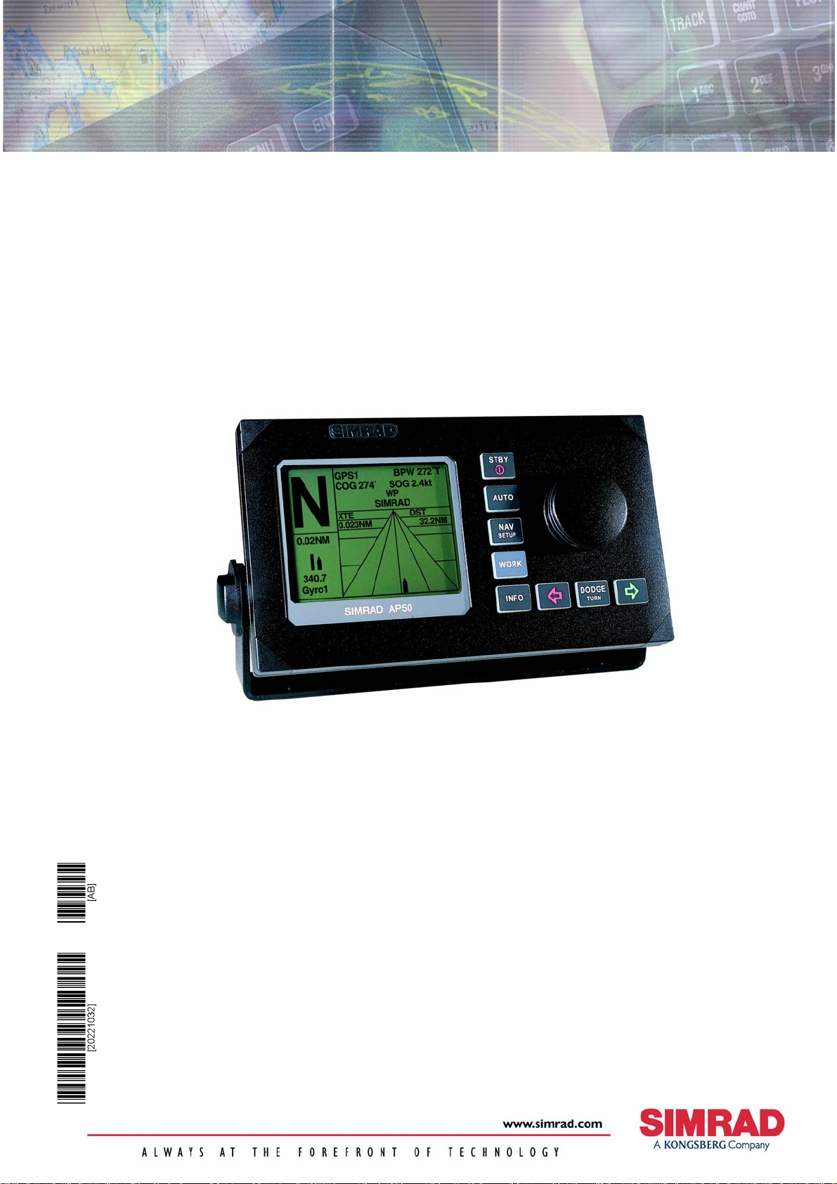
Simrad AP50
Autopilot

Note!
Simrad AS makes every effort to ensure that the information contained within this
document is correct. However, our equipment is continuously being improved and
updated, so we cannot assume liability for any errors which may occur.
Warning!
The equipment to which this manual applies must only be used for the purpose for
which it was designed. Improper use or maintenance may cause damage to the
equipment or injury to personnel. The user must be familiar with the contents of the
appropriate manuals before attempting to operate or work on the equipment.
Simrad AS disclaims any responsibility for damage or injury caused by improper
installation, use or maintenance of the equipment.
Copyright
© 2003 Simrad AS
The information contained within this document remains the sole property of
Simrad AS.
No part of this document may be copied or reproduced in any form or by any
means, and the information contained within is not to be communicated to a third
party, without the prior written consent of Simrad AS.

General Information
Instruction Manual
This manual is intended as a reference guide for the correct
installation and operation of the Simrad AP50 autopilot.
Great care has been taken to simplify the set-up and
operation of the AP50; however, an autopilot is a complex
electronic system. It is affected by sea conditions, speed of
the vessel, and vessel hull shape and size.
Please take the time to read this manual to gain a thorough
understanding of the Simrad AP50 autopilot’s system
components and operation, as well as their relationship to a
complete AP50 autopilot system.
Other documentation included in this manual is a warranty
card. This card must be completed by the authorized dealer
that performed the installation and mailed-in to activate the
warranty.
Caution ! An autopilot is a very useful navigational aid, but it DOES
NOT under any circumstance replace a human navigator.
Do not use automatic steering when:
• In heavy traffic areas or in narrow waters
• In poor visibility or extreme sea conditions
• When in areas where use of autopilot is prohibited by law
When using an autopilot:
• Do not leave the helm unattended
• Do not place any magnetic material or equipment near any
magnetic or fluxgate compass used in the autopilot system
• Verify the course and position of the vessel at regular
intervals
• Always switch to Standby mode and reduce speed in
sufficient time to avoid hazardous situations
20221032B 1

Simrad AP50 Autopilot
Document revisions
Rev Date Written by Checked by Approved by
A 03.06.02 NG GK GHR
B 18.06.03
Document history
Rev. A Original Issue
Rev. B Updated according to software revision V1R2.
Minor corrections in text. RF14XU added.
2 20221032B

General Information
Contents
1 GENERAL INFORMATION .............................................................................11
1.1 Introduction ..................................................................................................11
1.2 How to Use This Manual..............................................................................12
1.3 System Components .....................................................................................13
1.4 AP50 Control Unit........................................................................................14
1.5 Junction Units ...............................................................................................14
1.6 Rudder Feedback Units ................................................................................14
RF300S Rudder Feedback Unit....................................................................14
RF45X Rudder Feedback Unit .....................................................................15
RF14XU Rudder Feedback Unit ..................................................................15
1.7 Heading Sensors ...........................................................................................15
RC25/RFC35R Rate Compass......................................................................15
CD100A Course Detector and CDI35 Course Detector Interface................15
General NMEA Compasses..........................................................................15
HS50 GPS Heading Sensor ..........................................................................15
Other Compass Models ................................................................................16
CI300X Compass Interface......................................................................16
GI50 Gyro Interface.................................................................................16
1.8 Optional Equipment......................................................................................16
AP51 Remote Control ..................................................................................16
R3000X Remote Control ..............................................................................16
S100 NFU Steering Lever ............................................................................17
S35 NFU Steering Lever ..............................................................................17
FU50 Follow-Up Steering Lever..................................................................17
F1/2 NFU Remote ........................................................................................17
TI50 Thruster Interface.................................................................................17
AD50 Analog Drive......................................................................................18
RI35 Mk2 Rudder Angle Indicator...............................................................18
NI300X NMEA Interface Unit .....................................................................18
2 OPERATION OF THE AUTOPILOT ..............................................................19
2.1 Overview ......................................................................................................19
2.2 ON/OFF - Standby Mode (STBY) ...............................................................22
2.3 AP50 with MSD50 Stern Drive unit.............................................................24
Zero point setting..........................................................................................24
Operation ......................................................................................................24
2.4 Follow-Up (FU) Steering..............................................................................25
2.5 Non-Follow-Up (NFU) Steering ..................................................................25
S100 (NFU) Steering Lever..........................................................................25
20221032B 3

Simrad AP50 Autopilot
F1/2 (NFU) Push Button Remote Control....................................................25
R3000X Remote Control (NFU) ..................................................................26
S35 NFU Steering Lever ..............................................................................26
2.6 Automatic Steering .......................................................................................27
AUTO Mode.................................................................................................27
AUTO-WORK Mode ...................................................................................28
2.7 Thruster Steering ..........................................................................................29
2.8 Navigating with the AP50 ............................................................................30
Route Navigation..........................................................................................31
Electronic Chart System (ECS) ....................................................................32
Selecting a Different Navigator....................................................................33
NAV-WORK Mode......................................................................................33
2.9 Dodging ........................................................................................................34
Dodging in AUTO Mode..............................................................................34
Dodging in NAV Mode ................................................................................35
2.10 TURN Mode .................................................................................................36
U-turn............................................................................................................36
C-turn............................................................................................................36
2.11 Multiple Station System ...............................................................................37
2.12 Lock Function...............................................................................................37
Standard Operation .......................................................................................37
Master Operation ..........................................................................................38
2.13 External system selection .............................................................................39
2.14 User Set-up Menu.........................................................................................39
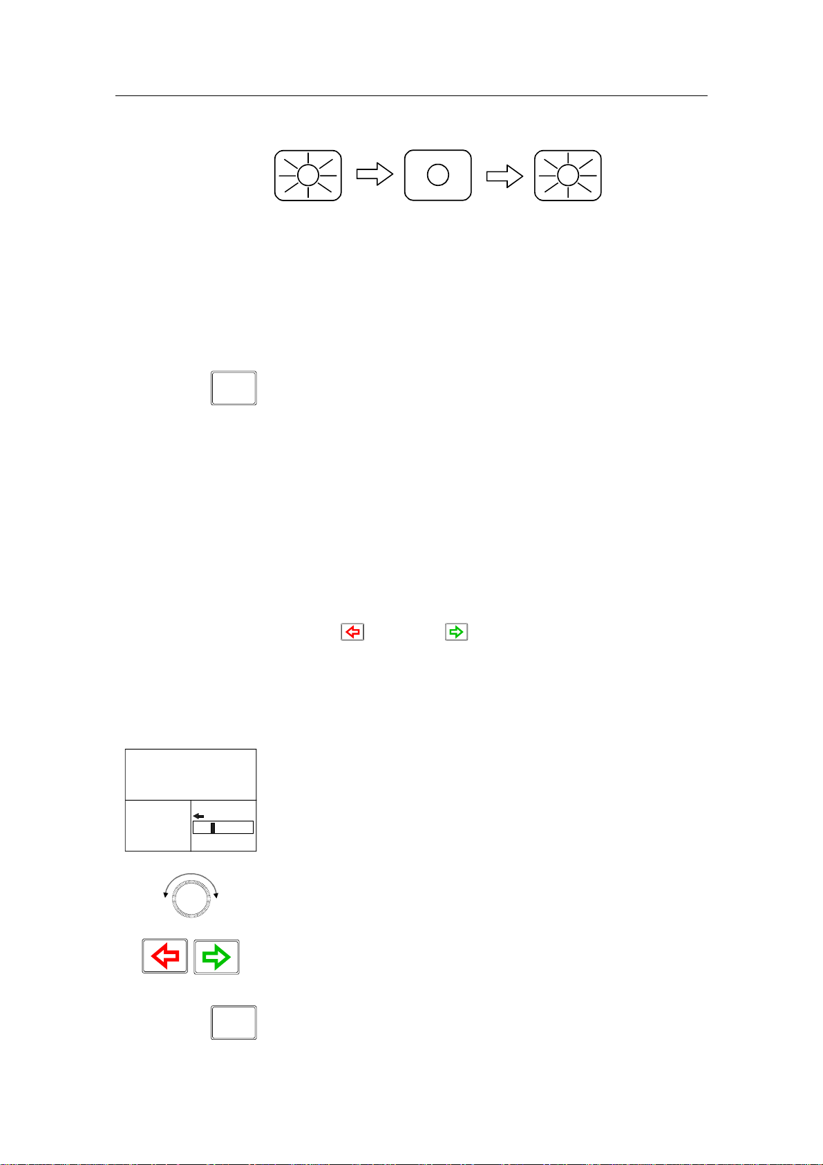
Alternating Course Knob Icon......................................................................39
STANDBY Mode .........................................................................................39
AUTO Mode.................................................................................................41
AUTO-WORK Mode ...................................................................................43
NAV Mode ...................................................................................................44
NAV-WORK Mode......................................................................................45
2.15 Instrument Screens and Menu ......................................................................46
Screen Selection ...........................................................................................48
Instrument Set-up. ........................................................................................48
3 TECHNICAL SPECIFICATIONS ....................................................................49
3.1 AP50 Autopilot System ................................................................................49
3.2 AP50 Control Unit........................................................................................50
3.3 AP51 Remote Control ..................................................................................51
3.4 Junction Units ...............................................................................................52
3.5 RC25/RFC35R Rate Compass......................................................................53
3.6 CDI35 Course Detector Interface .................................................................54
4 20221032B

General Information
3.7 CD100A Course Detector.............................................................................55
3.8 CD109 Course Detector................................................................................55
3.9 RI35 Mk2 Rudder Angle Indicator...............................................................56
3.10 RF300S Rudder Feedback Unit....................................................................57
3.11 RF45X Rudder Feedback Unit .....................................................................58
3.12 RF14XU Rudder Feedback Unit ..................................................................59
3.13 GI50 Gyro Interface......................................................................................60
3.14 CI300X Compass Interface ..........................................................................61
3.15 NI300X NMEA Interface .............................................................................62
3.16 TI50 Thruster Interface.................................................................................63
3.17 AD50 Analog Drive......................................................................................63
3.18 R3000X Remote Control ..............................................................................64
3.19 S100 NFU Steering Lever ............................................................................65
3.20 S35 NFU Steering Lever ..............................................................................65
3.21 F1/2 Remote Control ....................................................................................66
3.22 FU50 Steering Lever ....................................................................................67
3.23 Environmental Protection .............................................................................68
3.24 NMEA Sentences .........................................................................................68
4 INSTALLATION .................................................................................................71
4.1 General..........................................................................................................71
4.2 Unpacking and Handling ..............................................................................71
4.3 Installation Index ..........................................................................................71
4.4 Determining System Configuration..............................................................73
4.5 AP50 System Layout ....................................................................................73
4.6 RF300S Rudder Feedback Unit....................................................................74
4.7 RF45X Rudder Feedback Unit .....................................................................76
Electrical Connection ...................................................................................77
Mechanical Alignment .................................................................................79
4.8 RF14XU Rudder Feedback Unit ..................................................................80
Mechanical mounting ...................................................................................80
Electrical installation ....................................................................................80
Final check....................................................................................................84
4.9 J50 Junction Unit ..........................................................................................85
Cable Connections........................................................................................85
Grounding and Radio Frequency Interface (RFI).........................................86
Junction Unit Terminals ...............................................................................86
System Select................................................................................................87
AUTO/STANDBY Toggling .......................................................................87
External Alarm (Non Wheelmark System)...................................................88
External Alarm (Wheelmark System) ..........................................................88
20221032B 5

Simrad AP50 Autopilot
4.10 Drive Unit Installation ..................................................................................89
Connecting a Reversible Pump.....................................................................91
Connecting a Hydraulic Linear Drive...........................................................92
Solenoids (externally powered, common positive)..................................92
Solenoids (externally powered, common negative).................................93
Connecting Solenoid Valves ........................................................................92
Solenoids (not externally powered) .........................................................93
4.11 Control Unit..................................................................................................94
Panel-mounting.............................................................................................94
Optional Bracket mounting ..........................................................................94
RobNet Network Cables...............................................................................95
AP51 Remote Control Connection ...............................................................98
AP51 in a Wheelmark System .................................................................98
JP21 Jack Point Installation..........................................................................98
4.12 RC25/RFC35R Rate Compass......................................................................99
RFC35 Fluxgate Compass ..........................................................................102
4.13 FU50 Steering Lever ..................................................................................102
4.14 TI50 Thruster Interface...............................................................................102
4.15 AD50 Analog Drive....................................................................................102
4.16 R3000X Remote Control ............................................................................103
4.17 S100 NFU Lever Installation......................................................................103
4.18 S35 NFU Steering Lever ............................................................................104
4.19 F1/2 Remote Control ..................................................................................104
4.20 Interfacing to Optional Equipment (THD, Navigation Receiver, etc.).......105
Single NMEA input/output.........................................................................105
Double NMEA input/output .......................................................................106
NMEA Compass In ....................................................................................106
Radar Clock/Data .......................................................................................107
Analog Heading Repeater...........................................................................107
Digital Heading Repeater ...........................................................................108
GI50 Gyro Interface....................................................................................109
NI300X NMEA Interface Unit ...................................................................111
CI300X Compass Interface Unit ................................................................112
CD100A Course Detector...........................................................................114
CDI35 Interface ..........................................................................................115
5 SOFTWARE SET-UP PROCEDURE .............................................................117
5.1 Description of Installation Set-up...............................................................117
5.2 Installation Menu........................................................................................118
Language selection .....................................................................................119
Dockside .....................................................................................................119
6 20221032B

General Information
Master Operation ...................................................................................121
Boat Type...............................................................................................121
Boat Length............................................................................................121
Drive Unit Voltage.................................................................................121
Rudder Feedback Calibration ................................................................122
Rudder Calibration.................................................................................123
Rudder Test............................................................................................124
Set Rudder Zero .....................................................................................125
Rudder Limit..........................................................................................125
Rudder Deadband...................................................................................125
Thruster..................................................................................................126
Interface Set-up...........................................................................................126
Sea Trial......................................................................................................132
Compass Calibration..............................................................................133
Compass Offset......................................................................................134
Set Thrust Direction, On/Off Thruster...................................................135
Thruster Calibration, Analog Thruster...................................................135
Thruster zero ..........................................................................................135
Direction and Maximum Thrust STBD, Analog Thruster.....................136
Direction and Maximum Thrust PORT, Analog Thruster.....................136
Minimum Thrust, Analog Thruster........................................................137
Speed source ..........................................................................................137
Set Cruising Speed.................................................................................138
Set Rudder Zero .....................................................................................138
Set Rate of Turn.....................................................................................138
Adjust rudder angle/Set rate of turn.......................................................139
Manual Tuning.......................................................................................140
Automatic tuning ...................................................................................141
Speed Response .....................................................................................143
5.3 Final Test ....................................................................................................143
5.4 Providing User Training .............................................................................144
6 ADVANCED SETTINGS..................................................................................145
6.1 Service Menu..............................................................................................145
System Data................................................................................................145
NMEA Data................................................................................................146
NMEA Port Test (J50 hardware)................................................................147
Master Reset ...............................................................................................147
6.2 Settings Menu .............................................................................................148
Steering.......................................................................................................148
W Init rudder..........................................................................................148
20221032B 7

Simrad AP50 Autopilot
W Autotrim ............................................................................................148
Autotrim.................................................................................................148
Course Adjust.........................................................................................149
Compass difference................................................................................149
Off Heading lim .....................................................................................149
Drive engage ..........................................................................................150
Drive type...............................................................................................151
Drive out ................................................................................................151
Prop. gain ...............................................................................................151
Seastate ..................................................................................................151
Rudder....................................................................................................151
Counter rudder .......................................................................................152
W Seastate ..................................................................................................152
W Rudder....................................................................................................152
W Count rudder ..........................................................................................152
W Rudder limit ......................................................................................152
Cruising speed........................................................................................152
Speed response.......................................................................................152
Transition Speed ....................................................................................153
Nav Gain ................................................................................................153
Minimum rudder ....................................................................................153
Turn mode..............................................................................................154
Rate of Turn ...........................................................................................154
W Rate of Turn ......................................................................................154
Radius ....................................................................................................154
W Radius................................................................................................154
Added stop time .....................................................................................154
Init NAV ................................................................................................155
Turn Gain...............................................................................................155
W Turn Gain ..........................................................................................155
Rate Sensitivity ......................................................................................155
Thruster.......................................................................................................156
Thruster inhibit.......................................................................................156
Thruster sensitivity.................................................................................156
Thruster gain ..........................................................................................156
Minimum thrust .....................................................................................157
Thruster hyst ..........................................................................................158
Thruster Drive........................................................................................158
Response delay.......................................................................................158
7 MAINTENANCE ...............................................................................................161
8 20221032B

General Information
7.1 Control unit.................................................................................................161
7.2 Junction Unit...............................................................................................161
7.3 Rudder Feedback ........................................................................................161
7.4 Compass (RC25/RFC35R) .........................................................................161
7.5 Drive unit....................................................................................................161
7.6 Exchange of software program...................................................................162
8 TROUBLESHOOTING ....................................................................................165
8.1 Warnings.....................................................................................................165
9 SPARE PARTS LIST ........................................................................................171
10 GLOSSARY........................................................................................................177
11 INDEX .................................................................................................................181
20221032B 9

Simrad AP50 Autopilot
This page is intentionally left blank
10 20221032B

1 GENERAL INFORMATION
1.1 Introduction
Congratulations on the purchase of your new Simrad AP50
autopilot system and thank you for selecting what we feel is one
of the most advanced autopilot systems available on the market
today.
Today, Simrad manufactures a complete range of autopilots for
all types of vessels, from leisure boats to advanced steering
systems for merchant marine vessels. Our factory for these
products Simrad Egersund AS, is located in Egersund on the
southwest coast of Norway. The company's involvement in
autopilots began in 1953 with equipment for the North Sea
fishing fleet under the brand name Robertson. Professional
mariners around the world acknowledge that the Robertson and
Simrad brand names are synonymous with the absolute best in
autopilot technology.
General Information
The AP50 autopilot from Simrad represents yet another step
forward in autopilot technology with the intent of providing
small fishing boats and work boats up to 200 feet with a host of
new features. The system can be expanded and enhanced with a
selection of options and accessories.
The brain in the AP50 autopilot system is the single "intelligent"
junction unit that communicates with all other system modules
on a RobNet network. The RobNet has been developed to
establish a reliable digital communication and power
distribution network between the units in the system. The
RobNet simplifies installation and enables the AP50 system to
be easily expanded at any time. Any unit that is connected to the
autopilot system via RobNet is called a RobNet Unit (See
Junction Unit Comparison table on page 14).
The AP50 system is produced and tested in accordance with the
European Marine Equipment Directive 96/98. This means that
the AP50 complies with the highest level of tests for nonmilitary marine electronic navigation equipment existing today.
The Marine Equipment Directive 96/98/EC (MED), as amended
by 98/95/EC for ships flying EU or EFTA flags, applies to all
new ships, to existing ships not previously carrying such
equipment, and to ships having their equipment replaced.
This means that all system components covered by annex A1
must be type-approved accordingly and must carry the
Wheelmark, which is a symbol of conformity with the Marine
Equipment Directive.
20221032B 11

Simrad AP50 Autopilot
While the AP50 may be installed on vessels not needing to
comply with the Marine Equipment Directive, those requiring
compliance must have one AP50 Control Unit set-up as a
“master unit” in order for the installation to be approved. Simrad
has no responsibility for the incorrect installation or use of the
AP50 autopilot, so it is essential for the person in charge of the
installation to be familiar with the relevant requirements as well
as with the contents of this manual, which covers correct
installation and use.
The purpose of the Marine Equipment Directive is to enhance
safety at sea and to prevent marine pollution through the
uniform application of the relevant international instruments
relating to equipment listed in Annex A1.
As there are many interfacing requirements in the
standards/codes, integrated systems and integrated certification
lead to more efficient and effective management of safety,
environmental, issues and quality.
The Marine Equipment Directive also constitutes a part of the
International Safety Management (ISM) Code. The ISM Code
was included as a new chapter (IX) of SOLAS in 1994, and is
mandatory for: passenger ships not later than 1st of July, 1998;
oil tankers; chemical tankers; gas carriers; bulk carriers and
cargo high speed craft of 500 gross tonnage and upwards not
later than 1st of July, 1998; and other cargo ships and mobile
offshore drilling units of 500 gross tonnage and upwards not
later than 1st of July, 2002.
It is required that both the shipping company and ships shall be
certified by the Administration (the government of the state
whose flag the ship is entitled to fly), by an organization
recognized by the Administration or by the government of the
country acting on behalf of the Administration.
1.2 How to Use This Manual
This manual is intended as a reference guide for installing,
operating and maintaining the Simrad AP50 autopilot. Great
care has been taken to simplify the set-up and operation and of
the AP50; however, an autopilot is a complex electronic system.
It is affected by sea conditions, speed of the vessel, and vessel
hull shape and size.
Please take the time to read this manual to get a thorough
understanding of the Simrad AP50 autopilot’s system
components and operation, as well as their relationship to a
complete AP50 autopilot system.
12 20221032B
General Information
At the end of this manual, you will find an index and a glossary,
which will help you when studying the manual.
Other documentation provided with your system includes a
warranty card.
Note ! The Warranty Card must be completed by the authorized dealer
that performed the installation and mailed-in to activate the
warranty.
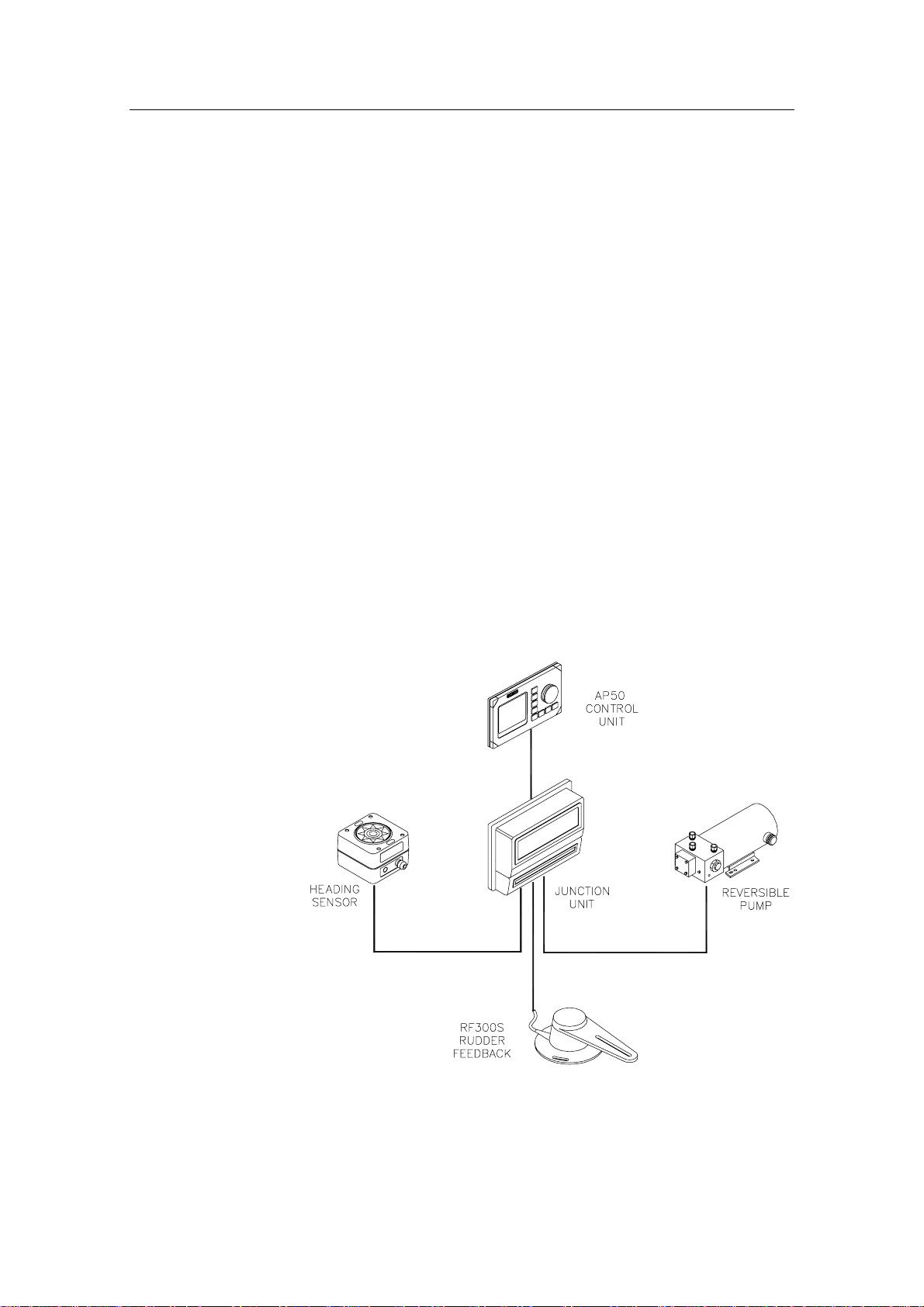
1.3 System Components
A basic AP50 system may consist of the following units (refer to
Figure 1-1):
• AP50 Control Unit with accessories
• Heading Sensor
• Rudder Feedback Unit with transmission link
• Junction Unit
• Drive Unit
The basic system can be expanded with remote control unit,
hand held remote and steering lever.
Figure 1-1 AP50 Basic system
20221032B 13

Simrad AP50 Autopilot
1.4 AP50 Control Unit
This compact autopilot control for panel, bulkhead- or bracketmounting has a rotary course knob and a large LCD for readout
of autopilot data. It also has two RobNet connectors for system
interconnection and expansion.
1.5 Junction Units
The junction unit in the AP50 autopilot system contains the
steering computer, interface circuits to all system components,
and drive circuits for the drive unit motor and clutch. Two
models, J50 and J50-40, are available.
J50 J50-40
Supply voltage 10-40 V 10-40 V
Motor current (continuous/peak) 10/20A 20/40A
Number of RobNet units* (+J50) 15 15
NMEA ports (input/output) 2 2
Solenoid output Yes Yes
Galvanic insulated solenoids Yes No
Input for NFU control Yes Yes
External alarm Yes Yes
Radar clock/data interface Yes Yes
* AP50 Control Unit, AP51 Remote Control, RFC35R Rate
Compass, FU50 Follow-up lever, CI300X Compass Interface,
NI300X NMEA Interface, TI50 Thruster Interface, AD50
Analog Drive.
Table 1-1 Junction Unit Model Comparison
1.6 Rudder Feedback Units
RF300S Rudder Feedback Unit
This rudder feedback unit with transmission link and 10 m (30
feet) of cable transforms the angular travel of the rudder to a
digital signal read by the autopilot steering computer. It is to be
used on small to medium size vessels.
14 20221032B

RF45X Rudder Feedback Unit
This rudder feedback unit with T45 transmission link and 2 m (6
feet) of cable transforms the angular travel of the rudder to a
digital signal read by the autopilot steering computer. It is to be
used on medium to large size vessels.
RF14XU Rudder Feedback Unit
This unit can replace the RF45X Rudder Feedback Unit in
installations where a more rugged construction of the feedback
unit is preferred. Besides electronic circuitry to generate
feedback signals for the autopilot and rudder angle indicators it
has been provided with 2 sets of limit switches.
1.7 Heading Sensors
The AP50 autopilot system can be used with the following
combinations of heading sensors:
General Information
RC25/RFC35R Rate Compass
The fluxgate compass with an integrated rate of turn sensor
provides a dramatic improvement to the dynamic performance of
both the autopilot and any stabilized radar display.
CD100A Course Detector and CDI35 Course Detector Interface
The sensor and interface unit connects the AP50 system to a
magnetic compass. The AP50 provides excitation current for
CD100A and converts the analog sine/cosine signal to digital
two-wire format for the autopilot steering computer.
General NMEA Compasses
Any compass outputting a NMEA 0183 message with either
HDT, HDG, or HDM sentence can be connected directly to the
J50/J50-40 junction units or to the NI300X NMEA Interface. An
output of 10 Hz is recommended.
HS50 GPS Heading Sensor
The Simrad HS50 is a GPS compass that displays true heading
output with position, velocity, and rate-of-turn information. This
product replaces several vessel instruments in one compact
package (gyrocompass, GPS system, and speed input).
The HS50 comprises three components: the sensor unit, the
interface unit, and the display unit.
20221032B 15

Simrad AP50 Autopilot
The sensor unit contains two GPS sensors and an inertial
element. This unit is to be mounted on the vessel mast. The
interface unit contains the main CPU and serial interface with
high-speed communication. The display unit contains a LCD for
navigation information and buttons for user control and
command. The interface unit and the display unit may be
mounted on the bridge. Refer to the HS50 manual.
Other Compass Models
CI300X Compass Interface
The optional CI300X Compass Interface can interface the AP50
with a magnetic compass via CD100A or CD109, a fluxgate
compass with heading signal on a sine/cosine format, and a
gyrocompass with 1:1 synchro.
GI50 Gyro Interface
This interface unit connects the geared synchro and stepper
gyrocompass and the 200P/NM speed log to the AP50 system.
Utilize the repeater signal output from the gyrocompass and the
pulse output from the speed log to generate a speed and heading
signal on NMEA format.
Note ! Supply a voltage of only 12 volts to the GI50.
1.8 Optional Equipment
A series of options are available for the AP50 system.
AP51 Remote Control
This portable remote control unit for AP50 with 7 m (23 ft.) of
cable can be used as a hand-held remote control or can be
mounted in a fixed bracket-mount.
The JP21 Jack Point can be used for simple connection/
disconnection of the AP51 at different locations on the vessel.
Refer to the AP51 manual.
R3000X Remote Control
This small hand-held remote control has two buttons for power
steering and course selection (port and starboard) and one button
with a built-in lighted indicator for (limited) mode selection.
16 20221032B

General Information
S100 NFU Steering Lever
The S100 Non-follow-up steering lever is designed for indoor
console mounting and it has a spring-loaded return-tomid-position feature.
S35 NFU Steering Lever
The S35 is designed for indoor and outdoor bulkhead-mounting
and is made of shock resistant polyxymethylene. The lever has a
spring loaded return-to-mid-position feature. Its push button
with light indicator is used for (limited) mode selection when
connected to an autopilot junction unit.
FU50 Follow-Up Steering Lever
The FU50 Follow-up steering lever features a dial (scale) with
5° rudder angle markings. The rudder will move and stop at the
angle selected on the dial. The FU50 has a mid-position indent,
buttons for (limited) mode selection, and mode indicators
(STBY, FU, AUTO, NAV, WORK, and THRUSTER). It is
designed for indoor and outdoor bulkhead- or panel-mounting.
Refer to the FU50 manual.
F1/2 NFU Remote
This handheld control for push-button steering is fitted with a
rubber grip and is made of cast seawater-resistant aluminum. It
is fitted with a 10 meter (33 ft.) cable.
TI50 Thruster Interface
The TI50 Thruster Interface is designed to provide a control
signal for operating a thruster in an AP50 system by either
on/off solenoids, analog ±10V control, or Danfoss PVEM valve.
The thruster output signal is calculated in the TI50 based on
operational mode and heading information received over
RobNet from other system units. Set-up from the control unit
and errors in the thruster interface are to be communicated via
RobNet. All settings are stored in the thruster interface unit.
Refer to the TI50 manual.
20221032B 17

Simrad AP50 Autopilot
AD50 Analog Drive
The AD50 Analog Drive is designed to provide a control signal
for operating an analog rudder in an AP50 system by either
analog or proportional ±10V control, or Danfoss PVEM valve.
The analog rudder output signal is calculated in the AD50 based
on operational mode and heading information received over
RobNet from other system units. Set-up from the control unit
and errors in the analog rudder interface are to be communicated
via RobNet. All settings are stored in the analog rudder interface
unit.
Refer to the AD50 manual.
RI35 Mk2 Rudder Angle Indicator
The RI35 Mk2 is manufactured in non-corrosive aluminum with a
non-reflective black finish.
The instrument gives a continuous reading of the rudder position
up to 45 degrees to each side of midship position. A front panel
key is used for rudder zero-adjustment, deflection reversal, and
illumination adjustment.
The splash-proof construction allows panel-, bulkhead-, or
bracket-mounting in exposed locations, such as the bridge wings,
the wheel house, and the engine room.
Refer to the RI35 Mk2 manual.
NI300X NMEA Interface Unit
This interface unit with 4 NMEA In/Out ports for
communication with other systems and a selectable heading
output for radars (Anritsu or Furuno), includes two RobNet
connectors for the AP50 system.
18 20221032B
Operation
2 OPERATION OF THE AUTOPILOT
Caution ! An autopilot is a very useful navigational aid, but it DOES
NOT under any circumstance replace a human navigator.
Do not use automatic steering when:
• In heavy traffic areas or in narrow waters
• In poor visibility or extreme sea conditions
• When in areas where use of autopilot is prohibited by law
When using an autopilot:
• Do not leave the helm unattended
• Do not place any magnetic material or equipment near the
magnetic or fluxgate compass used in the autopilot system
• Verify the course and position of the vessel at regular
intervals
• Always switch to Standby mode, and reduce speed in
sufficient time to avoid hazardous situations
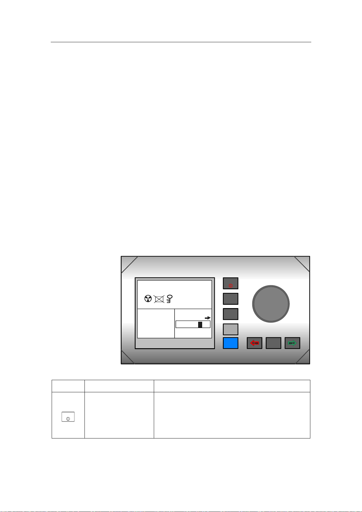
2.1 Overview
SIMRAD
CTS
A
UTO
Inactive
340.
Gyro1
329
RUDDER
7
04
SIMRAD AP50
Figure 2-1 AP50 Front Panel
Buttons Action Function
STBY
AUTO
NAV
SETUP
WORK
INFO
DODGE
TURN
Short press: Switches the system on. Selects STANDBY mode.
STBY
Long press (3 sec.): Switches the system off.
Quick double press: Locks or unlocks other control units and levers in
the system.
20221032B 19

Simrad AP50 Autopilot
Buttons Action Function
Single short press: Selects AUTO mode and sets the heading
AUTO
reference.
Second short press Sets new heading reference.
Short press: Selects NAV mode prompt screen from AUTO
mode.
NAV
SETUP
WORK
INFO
DODGE
TURN
Verifies new course to steer when alert screen is
shown (can also use the course knob, see below).
Quick double press: Selects User Set-up menu for selected mode.
Long press (5 sec.): Selects Installation menu.
Short press: Selects AUTO-WORK mode when in STANDBY
mode.
Selects/deselects AUTO-WORK mode when in
AUTO mode.
Selects/deselects NAV-WORK mode when in
NAV mode.
Short press: Selects Instrument screens.
Long press (5 sec.): Selects units to be displayed.
Quick double press: Selects Instrument screens to be shown.
Short press: Activates Dodging.
Long press (3 sec.): Activates U-turn.
Second long press: Activates C-turn.
Press in STANDBY
Rudder moves to port while button is pressed.
mode:
Press in AUTO
mode:
Press in User Set-up
Adjusts course to port (1°, 5°, or 10°).
Reverts to previous menu item.
or Installation
menus:
Press in STANDBY
Rudder moves to stbd. while button is pressed.
mode:
Press in AUTO
mode:
Press in User Set-up
Adjusts course to starboard (1°, 5°, or 10°).
Proceeds to next menu item.
or Installation
menus:
20 20221032B
Buttons Action Function
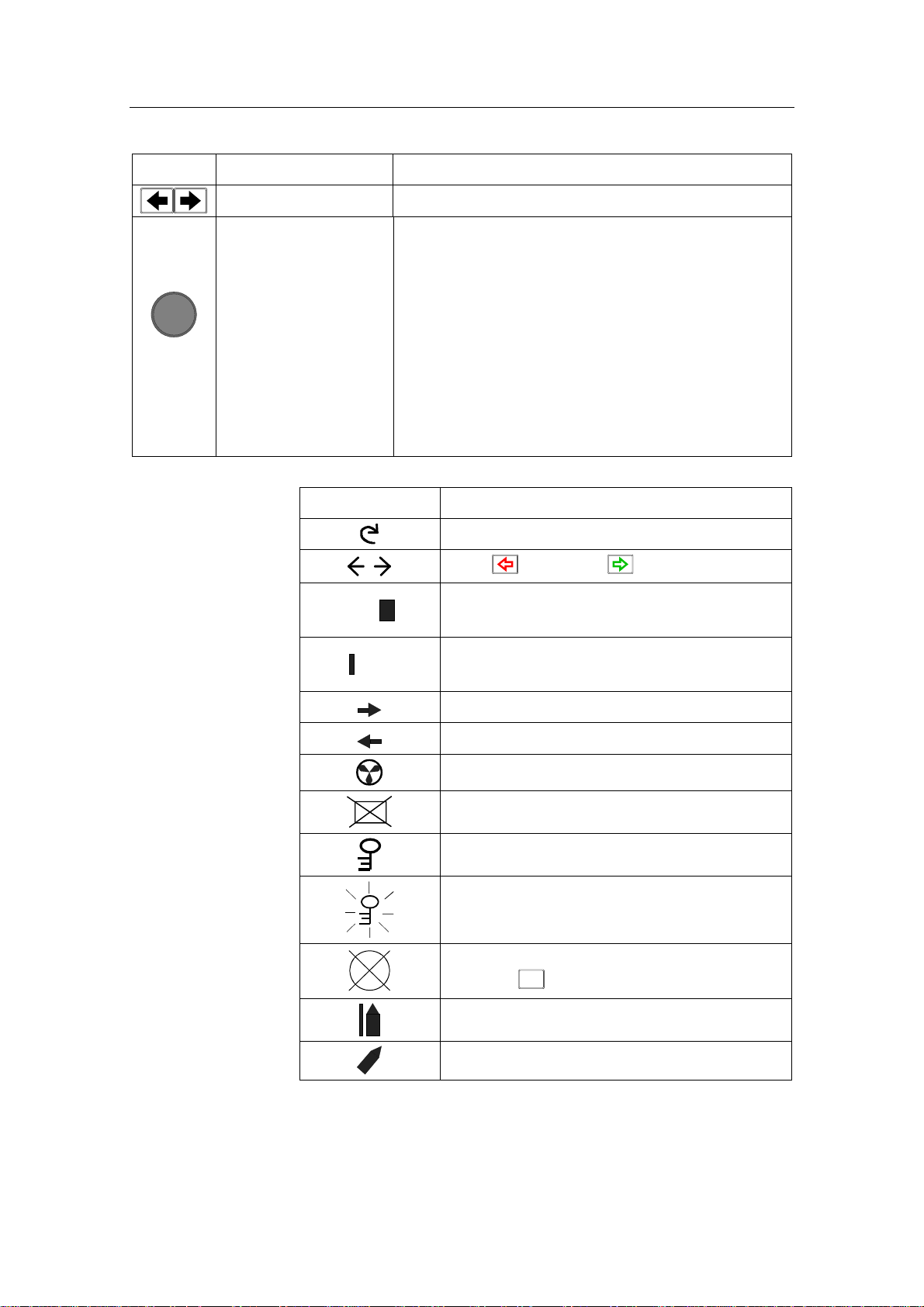
Press simultaneously Activates Follow-up steering mode.
Operation
Course
knob
Rotate in Follow-up
steering mode:
Rotate in AUTO
mode:
Rotate in NAV
mode:
Rotate in User Set-up
or Installation
menus:
Screen Symbol Description
Sets commanded rudder angle.
Counter clock-wise = Port course change
Clock-wise = Starboard course change
Verifies new course to steer when alert screen is
shown.
Adjusts or confirms reading.
Rotate course knob
Press (PORT) or (STBD) button
Rudder angle 4° to starboard
04
(Rudder command when analog rudder)
Rudder angle 2° to port
02
(Rudder command when analog rudder)
Rudder command to starboard
Rudder command to port
Thruster connected to autopilot system
Control unit inactive or disengaged
Control unit locked
Key symbol alternates with mode index on
unlocked master unit
No course changes can be made unless you
press the
Cross track error to starboard
Boat turning to starboard
AUTO
(AUTO) button
20221032B 21

Simrad AP50 Autopilot
The control unit shown in Figure 2-1 on page 19 can operate as
a stand-alone unit in an autopilot system or it can be combined
in a multistation system. In a multistation system, command can
easily be transferred from one unit to another and units not in
control will display "Inactive".
The autopilot system may also be disabled from the ships’
steering system with an external switch. This will totally
disengage the autopilot system from the ships’ main/emergency
steering system and the units will display “DISENGAGED”.
The AP50 system is capable of the following primary steering
modes with each mode having a dedicated push button:
STANDBY (Follow-up and Non-Follow-up), AUTO, NAV and
DODGE. AUTO and NAV modes also have a sub-mode that is
accessed by pressing the WORK button. The AUTO-WORK
and NAV-WORK sub-modes are used under operational
conditions different from those normally found when a vessel is
in transit on a preset course (e.g. trawling, towing, trolling on
one engine, slow speed, using a thruster, etc.).
Each of the mode buttons is clearly identified with the primary
function in large text and a secondary function listed in smaller
text. Each button provides you with the ability to access a
primary display, a secondary display, and/or multiple function
displays.
A group of user-adjustable settings belonging to the selected
mode are provided in the AP50 User Set-up Menu (see page 38).
The settings allow adjustment of display visibility, selection of
heading sensor, navigation and position sources, and the ability
to select between automatically or manually adjustable sea state
filter.
Alarms are presented in plain text to alert you to both system
and external data failure conditions. Alarms include both audible
and visual presentations. The alarms are listed on page 165.
2.2 ON/OFF - Standby Mode (STBY)
A single press on the
ON and the following status displays are shown:
STBY
(STBY) button switches the system
Simrad
AP50
SW V1R2
HW rev. 0
Autopilot model
Software V(ersion) and R(elease)
Hardware revision
22 20221032B
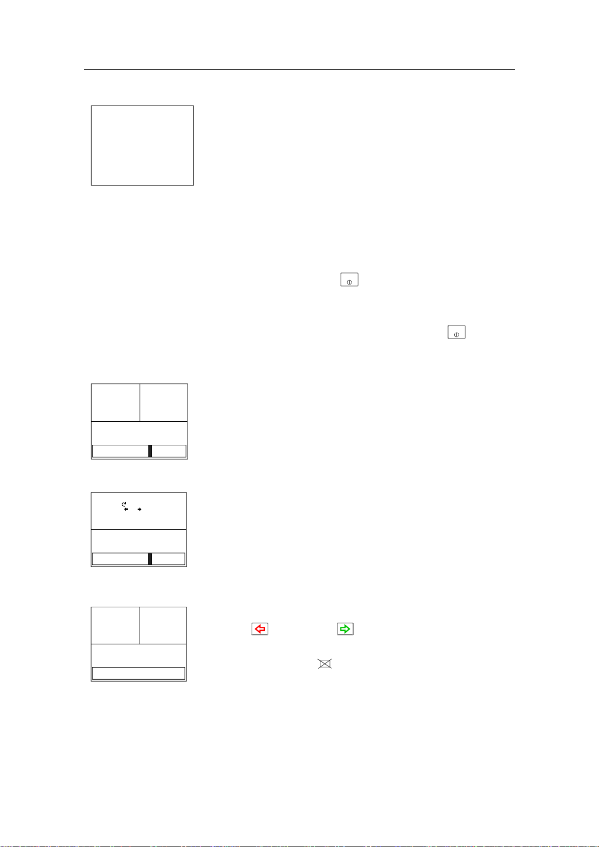
Operation
Simrad
J50
SW V1R2
P05 M00 S000
Software V(ersion) and R(elease)
Power board revision, Main board revision and Self check
(SW and HW revisions shown are examples only)
After approximately 5 seconds, the system is operative and the
unit that was turned on will show the STANDBY mode
display. Other units in a multistation system will display
"Inactive". Control can be transferred to any single unit by
pressing any of its’ mode buttons (except in a Wheelmark
system; see the Introduction on page 11).
Junction unit model
STBY
A long press (3 sec.) on the
(STBY) button switches the
system off and during this time, the alarm will sound.
Note ! In an emergency, it is possible, on a multistation system, to turn
OFF the system at any control unit by pressing the
STBY
(STBY)
button for 3 seconds (except in a Wheelmark system).
STANDBY mode is used when steering the boat at the helm.
Display information:
S
TBY
340.
Gyro1
7
• Standby mode
RUDDER
02
ADJUST COMPASS INPUT?
Adjust:
OK? Press or
Gyro2
Heading 018°
Offset +018°
RUDDER
02
Stepper or Synchro
gyro
S
TBY
340.
RUDDER
7
Gyro1
- -
Analog rudder
• Current heading from gyro 1: 340.7°
• Rudder angle: 2° to starboard. When there is no rudder
feedback signal (analog rudder drive) the rudder readout
shows – –).
If a stepper or synchro gyro is connected to the autopilot system
via the GI50 Gyro Interface, a display for the heading
adjustment is presented at Power On or at change of compass in
the User Set-up menu. Use the course knob to align the autopilot
read-out to correspond with the gyro heading. Check the
alignment every time the autopilot/gyro is switched on. If two
stepper gyros are connected, both will simultaneously be
aligned. A stepper gyro used as monitor compass will
automatically be aligned to the steering compass.
Press the
(PORT) or (STBD) button to proceed to
Standby mode.
If the inactive symbol
FU50 or while Disengaged) the Control unit must be activated
is shown (when powered up from
before alignment by pressing the STBY button.
20221032B 23
Simrad AP50 Autopilot
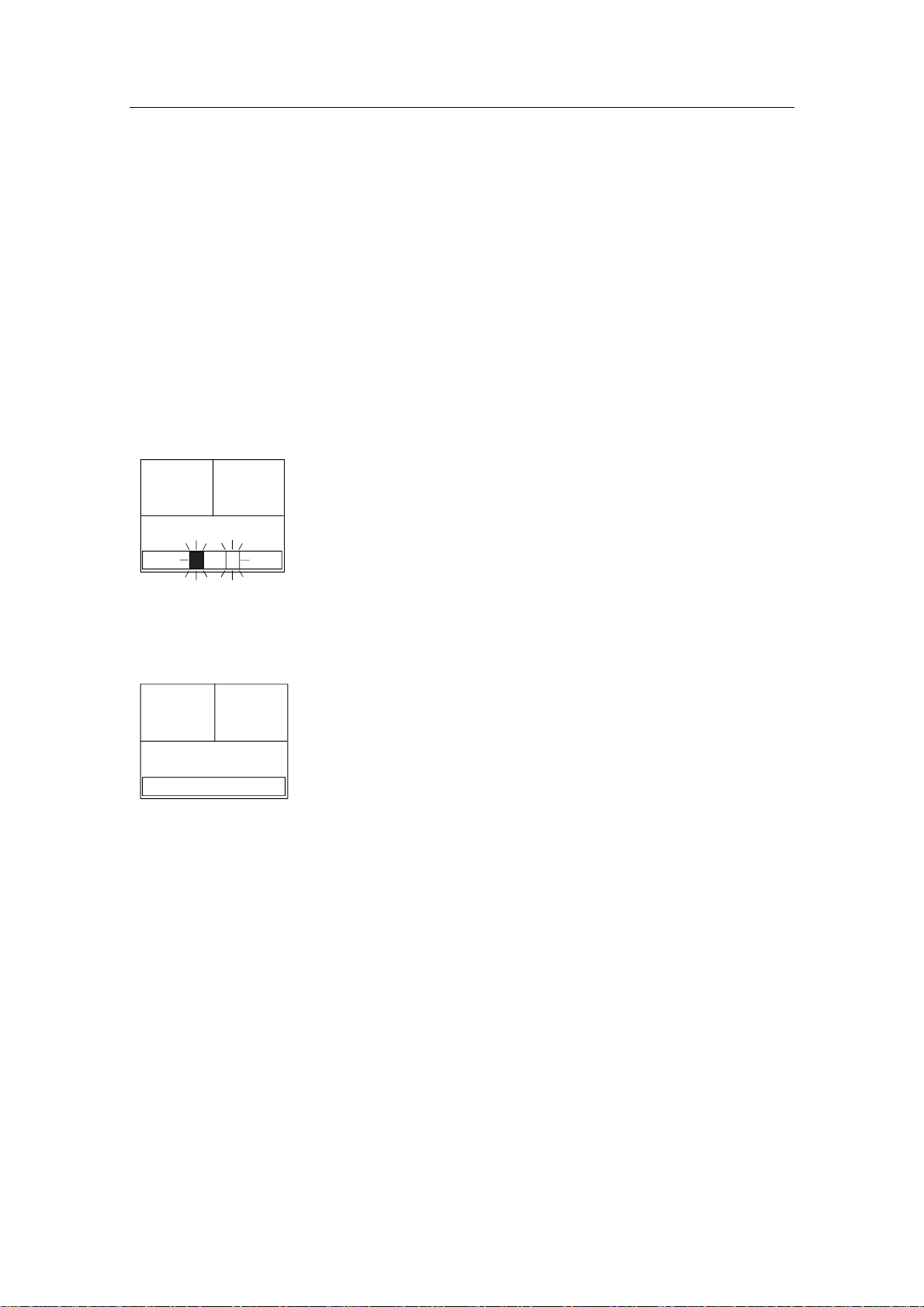
2.3 AP50 with MSD50 Stern Drive unit
Note ! The information in section 2.3 only applies if your autopilot is
driving a Simrad MSD50 Stern Drive.
The MSD50 Stern drive unit has a relative feedback signal which
needs a zero point setting after the autopilot has been turned on.
Refer to the MSD50 manual for further information.
Zero point setting
Note ! If you do not need a rudder angle display when leaving the dock,
just steer the boat manually on a straight course and press the
AUTO button. The zero point is then set automatically.
If you prefer to use the rudder angle display when leaving the
S
TBY
340.
RUDDER
10
Gyro1
7
dock, proceed as follows:
After turn on the rudder angle display will alternate between 10
degrees port and starboard to indicate that the "rudder" zero point
need be set.
Use the wheel to bring the "rudder" to midship position. Turn the
wheel from lock to lock (H.O. to H.O.) and count the exact
number of turns. Then start from one lock position and turn the
half number of turns.
S
TBY
340.
Gyro1
RUDDER
00
Press the AUTO button and then the STBY button. The zero point
7
is now set and the following display is shown.
Operation
Follow the operating instructions on the following pages. There is
no further need for zero point settings until next time you turn the
autopilot on.
24 20221032B
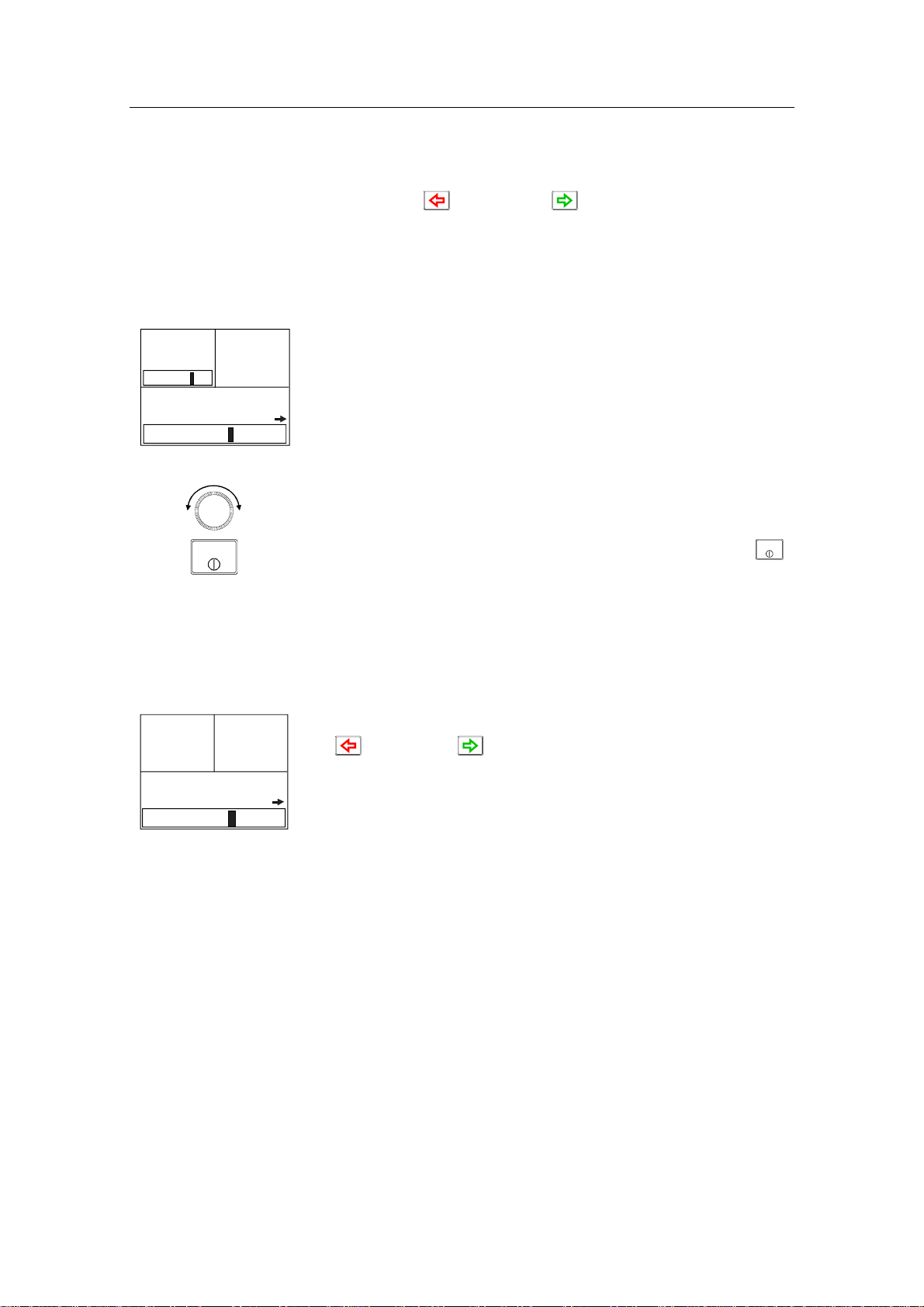
2.4 Follow-Up (FU) Steering
When both the (PORT) and (STBD) buttons are pressed
simultaneously, the AP50 will enter Follow-Up steering mode
and the course knob may be used to set rudder commands. One
revolution of the knob equals a 45° rudder change. The rudder
will move to the selected angle and stop.
Operation
FU
PS
03
340.
Gyro1
RUDDER
02
Display information:
7
• Follow-Up mode
• Commanded rudder angle: 3° to starboard
• Rudder angle: 2°
• The small starboard arrow shows that the rudder is moving.
Use the course knob to select the rudder angle.
P
STBY
S
Return to manual control in Standby mode by pressing the
(STBY) button.
While in Follow-Up mode, you cannot take manual control
of the vessel unless you use the External Mode Selector.
2.5 Non-Follow-Up (NFU) Steering
NFU
RUDDER
340.
Gyro1
02
In STANDBY mode, the NFU display is presented when either
7
the (PORT) or (STBD) button is pressed. The rudder
will move as long as the button is pressed and the actual rudder
angle is shown on the display. The small arrow shows that the
rudder is moving.
STBY
Note ! When a NFU steering lever or remote control is operated, the
control unit(s) become "Inactive".
For safety reasons NFU steering is not possible when an analog
rudder is controlled from AD50 Analog Drive
S100 (NFU) Steering Lever
In STANDBY mode, the rudder will move as long as the lever is
offset to Port or Starboard.
F1/2 (NFU) Push Button Remote Control
In STANDBY mode, the rudder will move as long as the Port or
Stbd button is pressed.
20221032B 25
Simrad AP50 Autopilot
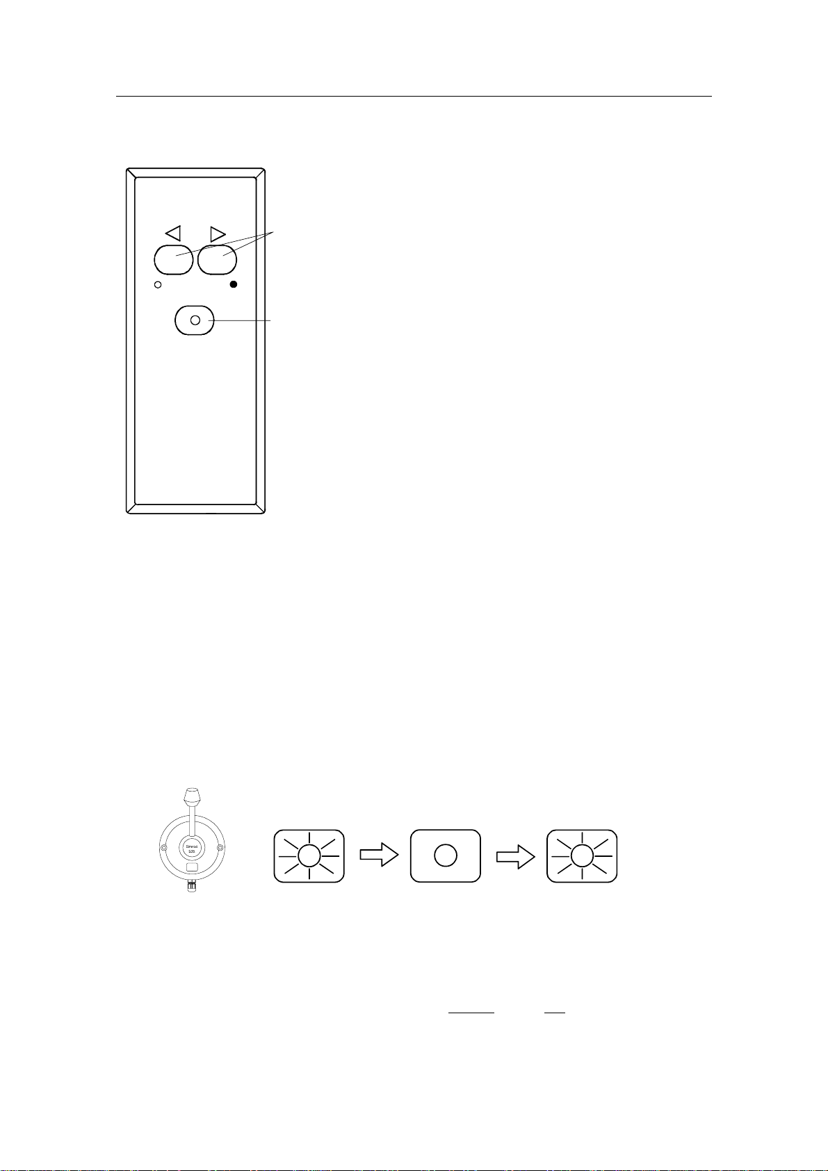
SIMRAD
STBY-AUTO
R3000X Remote Control (NFU)
In STANDBY mode, the rudder will
move as long as the Port or Stbd button
Push buttons for Port and
Stbd NFU commands
STBY/AUTO mode button.
AUTO or NAV mode is
when lamp is lit
is pressed.
In AUTO mode the set course will
change 1° each time the button is
pressed.
Note!
If you keep the button pressed, it will
automatically change the course in
increments of 3° per second.
Pressing the mode button returns the
autopilot to the initial mode, except
when in NAV mode:
Simrad R3000X
AUTO → STBY → AUTO
AUTO-WORK → STBY → AUTO-WORK
NAV → STBY →AUTO
NAV-WORK → STBY → AUTO-WORK
Note ! NAV mode can only be entered from a control unit or AP51
Remote Control Unit.
S35 NFU Steering Lever
STANDBY: The rudder will move as long as the lever is offset to Port or
Starboard (Non-follow-up steering).
AUTO/AUTO-
WORK: The set course will be changed by 3° per second when the lever
is offset to Port or Starboard or 1° for single activation.
The mode button remains lit as long as the autopilot is in AUTO
or AUTO-WORK mode (and NAV mode).
The mode change sequence is as follows:
AUTO STBY
AUTO
AUTO-WORK
STBY
AUTO-WORK
Pressing the mode button returns the autopilot to the initial
mode at the present course.
NAV/NAV-
WORK: It is not possible to change the set course by the lever. Pressing
the mode button brings the autopilot to STANDBY mode, but
the next press brings it to AUTO
mode, not back to NAV mode.
26 20221032B
NAV STBY AUTO
Operation
NAV-WORK
STBY AUTO-WORK
Note ! NAV-WORK mode can only be entered from a control unit or
AP51 Remote Control Unit.
2.6 Automatic Steering
AUTO Mode
AUTO
AUTO mode is used to make the AP50 steer the vessel
automatically on a set heading. AUTO mode is always available
from any mode or function within the AP50 by a single push of
the AUTO button. When AUTO mode is selected, the AP50
automatically selects the current vessel heading as the set
heading and the rudder will move to midship position.
The W Init rudder setting has no effect.
In AUTO, the AP50 issues rudder commands to keep the boat
on the set heading. The boat heading is provided by the steering
compass.
The AP50 will keep the boat on the set heading until a new
mode is selected or a new heading is set with either the course
knob, the (PORT) or (STBD) buttons, or by pushing the
AUTO button again. One revolution of the knob equals a 45°
course change.
Once the course is changed to a new set heading, the boat will
automatically turn to the new heading and continue to steer
straight.
Display information:
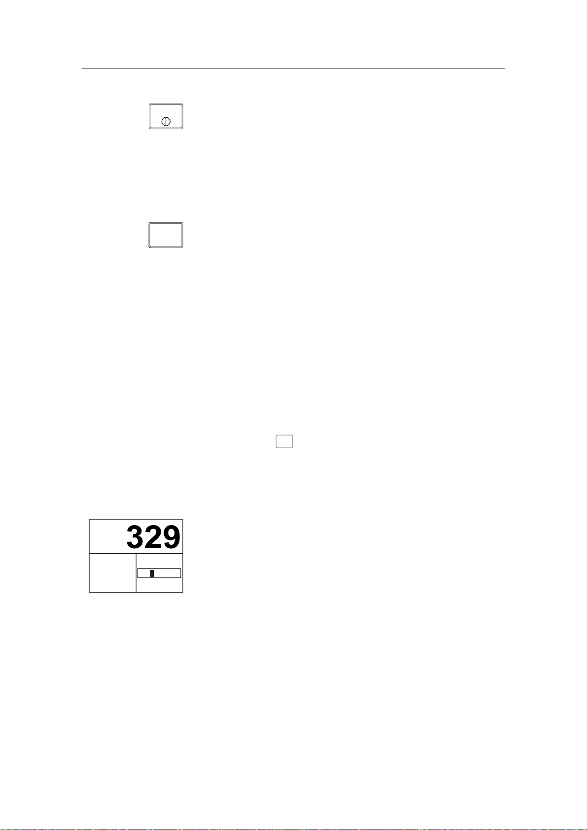
A329
340.
Gyro1
RUDDER
7
02
• Automatic steering mode
• Set heading: 329°
• Boat heading from gyro compass: 340.7°
• Rudder angle: 2° to port and still moving
Rotate the course knob to change the course:
Clock-wise = Starboard course change
Counter Clock-wise = Port course change
Press the PORT or STBD button to adjust the course by 1°. It is
possible to set the buttons to adjust the course by 5° or 10° per
press in the Installation menu (see page 148).
AUTO
20221032B 27
Press the AUTO button to select current vessel heading as set
heading.
Simrad AP50 Autopilot
STBY
Press the STBY button to regain manual steering
AUTO-WORK Mode
The AUTO-WORK mode is an automatic steering mode to be
used under operational conditions different from those normally
found when a vessel is in transit on a pre-set course. Examples
are trawling, towing, trolling on one engine, slow speed etc.
WORK
In such situations, some boats may need different settings. By
pressing the WORK button, a separate set of steering and turning
values will be used. It can also be set how the rudder should
move when entering AUTO-WORK from STANDBY or
DODGE.
If W Init Rudder “Actual” is selected (see settings on page
148), the rudder offset is maintained and becomes the Trim
value (bumpless transfer).
If W Init Rudder “Midship” is selected, the rudder will move to
midship (0°)
When selecting WORK from any automatic mode and when
changing between heading and route steering, the rudder offset is
always maintained.
To manually change the Trim or other WORK settings, quickly
NAV
double press the
SETUP
(NAV/SETUP) button (see AUTO-WORK
mode in the User Set-up menu on page 43).
If Thruster is selected under the Steering function in the User
Set-up Menu, the thruster will be used when selecting WORK
mode.
Display information:
A
w
S345
RUDDER
340.
Gyro1
7
04
• AUTO-WORK mode
• Set heading: 329°
• Boat heading from gyro compass: 340.7°
• Rudder offset of 4° to port becomes the Trim value
If you prefer to have complete manual control of the rudder trim
in AUTO-WORK mode, the Autotrim can be permanently
disabled in the Installation Settings menu (see page 148).
Caution ! The Off Heading alarm is permanently disabled in AUTO-
WORK mode.
Note ! Pair-trawling requires manual trim only, and the autotrim
should be permanently disabled at the Installation Settings
menu.
28 20221032B

2.7 Thruster Steering
If the vessel is equipped with a thruster, it can be connected to
the AP50 system and the vessel can then be controlled by
rudder, thruster, or both rudder and thruster.
After connecting a thruster to the autopilot system (see the TI50
manual) the thruster type must be selected under the Installation
Dockside menu (see page 126).
A thruster icon below the mode index indicates that a thruster is
connected to the system.
Now you can select one of three control functions from the User
Set-up Menu:
• Rudder: The rudder is used to maintain the heading (always
in AUTO mode and NAV mode).
• Thruster: The thruster is used to maintain the heading (only
in AUTO-WORK, NAV-WORK, Follow-up, and NonFollow-up steering modes).
Operation
• Rudder and Thruster: Both rudder and thruster are used to
maintain the heading (only in AUTO-WORK mode, NAVWORK mode, Follow-up and Non-Follow-up steering
modes).
Examples of display pictures:
STANDBY
mode
(Follow-up
and Nonfollow up
steering
modes)
AUTOWORK
mode
Heading maintained
S
TBY
Heading to be
maintained by rudder
w
A
340.
Gyro1
RUDDER
02
7
271
RUDDER
263.
Gyro1
by rudder
7
02
S
TBY
Heading to be maintained
by thruster
w
A
340.
02
7
Gyro1
271
263.
Heading maintained by
Gyro1
7
thruster
02
S
TBY
Heading to be maintained
by rudder and thruster
w
A
340.
02
7
Gyro1
271
263.
Heading maintained by
rudder and thruster
Gyro1
7
02
20221032B 29

Simrad AP50 Autopilot
Caution ! When operating an On/Off thruster it is important to note that
most electrical thrusters have a built in thermal cut-off switch
that will shut off the electromotor if it is overheating and reengage it when it has cooled down. The water temperature also
affects the running time. The On/Off thruster may only run for
a few minutes, and its total running time for a longer period
should be limited by increasing the thruster sensitivity value
(see page 156).
2.8 Navigating with the AP50
The AP50 has the capability to use steering information from an
external navigator (GPS/Chart plotter or ECS) to direct the boat
to one specific waypoint location or through a series of
waypoints. In the NAV mode, the AP50 uses the heading sensor
as its heading source for course keeping. The steering and speed
information received from the external navigator alters the set
course to direct the AP50 to the destination waypoint.
Note ! Navigational steering must only be used in open waters. By
selecting the NAV mode, the AP50 is set for automatic steering
on the current set course to a destination waypoint.
To obtain satisfactory navigation steering, the following
conditions must be fulfilled prior to entering the NAV mode:
• The AP50 autosteering must be tested and determined
satisfactory
• The navigation receiver must be operating and the navigation
system (GPS/Chart plotter or ECS) must be in full operating
mode with adequate signal characteristics for valid position
and steering data
• At least one waypoint must be entered and selected as the
current waypoint in the navigation receiver
• The navigation source in the AP50 User Set-up menu must be
set for the navigator that contains the current waypoint
The AP50 is designed to steer in mixed mode operation. This
combines the straight steering capability of Cross Track Error
(XTE) steering in conjunction with the turning capability of
bearing mode steering (Course To Steer [CTS]).
NAV
SETUP
Press the NAV button to activate the NAV prompt display.
30 20221032B

Operation
WP: SIMRAD
BWW :
Chg :
OK? Press NAV
340.
Gyro1
7
270°
70°
RUDDER
01
The upper half of the prompt display shows the name of the next
waypoint (WP), the bearing to the waypoint (BWW), and the
required course change (Chg) with the direction in which the
vessel will turn.
The lower left portion shows the compass heading and the lower
right portion shows the rudder angle and port direction.
Press NAV to accept the first waypoint as the location to steer
towards. The autopilot turns the boat onto the new course.
Display information:
• NAV mode
NM
• Course To Steer (CTS): 340° is set internally in the autopilot
°T
NM
to steer the boat along the track
• Nav source: GPS1. The boat is located on the track
340.
Gyro1
NAV
SETUP
340°
CTS
GPS1
XTE
.000
NEXT WP
SIMRAD
7
BPW
340
DST
25
• Cross Track Error (XTE): 0.000 nautical mile
Note ! For Cross Track Error, the number of decimals shown
depends on the output from the chart plotter. Three decimals
give a more precise steering.
• Compass heading from Gyro1: 340.7°
WP: WP2
BWW
Chg.
OK? press NAV
135.
Gyro1
7
100°
035°
NEXT WP
WP2
BPW
102
DST
02.2
NAV
SETUP
• Next waypoint: Simrad
• Bearing from the current position to the next waypoint
(BPW): 340°
• Distance to this waypoint: 25 nautical miles
Route Navigation
When operating the AP50 in NAV mode to automatically steer
through a route of waypoints, the AP50 will steer to the first
waypoint in the route after you accept the first waypoint as the
location to steer towards.
If you use a GPS/Chart plotter, the AP50 will, when you arrive
at the waypoint, output an audible alarm and display an alert
screen with the proposed new course information. If the required
course change is more than 10°, you will need to verify that the
°T
upcoming course change is acceptable.
NM
Verification is performed by pressing the NAV button or turning
the course knob after the alert screen is displayed. If an external
alarm unit (optional) is connected to the AP50 system, an alarm
is given after 5 seconds. If no verification is received, the AP50
will continue on the current set course in NAV mode.
20221032B 31

Simrad AP50 Autopilot
Origin
The new heading is accepted
automatically after the
NAV/SETUP button is pressed
B
PW
WP1
Waypoint arrival zone
(determined by the navigator)
Regain manual steering at any time by pressing the
B
W
W
WP2
STBY
(STBY)
button.
Note ! If the AP50 is connected to a navigation receiver that does not
transmit a message with the bearing to the next waypoint, it will
pick a Cross Track Error message and steer on Cross Track
Error only. In that case you have to revert to AUTO mode at
each waypoint and manually change the set course to equal the
bearing to the next waypoint and then select NAV mode again.
Electronic Chart System (ECS)
NAV
SETUP
WP: SIMRAD
BWW :
Chg :
Auto WP shift OK? Press NAV
340.
Gyro1
270°
70°
7
RUDDER
01
An ECS has to be selected as NAV source.
Press the NAV button to activate the NAV prompt display.
The upper half of the prompt display shows the name of the next
waypoint (WP), the bearing to the waypoint (BWW), and the
required course change (Chg) with the direction in which the
vessel will turn.
The lower left portion shows the compass heading and the lower
right portion shows the rudder angle and direction.
NAV
SETUP
N
340.
Gyro1
ECS1
Chg
TURNING
7
NEXT WP
BPW
DST
020°
SIMRAD
270
25
Press NAV to accept the first waypoint as the location to steer
towards. The autopilot turns the boat onto the new course while
the display flashes “TURNING”.
Accepting the first waypoint as the location to steer towards you
also accept the autopilot to automatically steer the boat through
the route of waypoints. When the autopilot changes the course at
°T
NM
each waypoint, the display flashes “TURNING”.
If you wish to confirm the new heading at each waypoint, GPS
has to be selected as NAV source.
A route consists of a series of waypoints joined together with
straight legs. Each waypoint in a route, except the first and the
last, has an associated turn radius defined. This turn radius will
allow the ship to turn before the waypoint is reached.
32 20221032B

Operation
Caution ! If an ECS is selected as a navigator, the course change
verification is waved. This is done so the AP50 is capable of
following a route in which the radius of the course change is
pre-set in the chart system. Users navigating in this mode must
use extra caution.
w
N
340.
Gyro1
Selecting a Different Navigator
If you have more than one navigation source connected to the
AP50, you may choose any for navigation. Refer to the User Setup menu in Standby mode for details on selecting a different
navigator (see page 39).
NAV-WORK Mode
The NAV-WORK mode is an automatic steering mode to be
used under operational conditions different from those normally
found when a vessel is in transit on a pre-set course. Examples
are trawling, towing, trolling on one engine, slow speed, etc.
WORK
280°
CTS
GPS1
XTE
.023
NEXT WP
SIMRAD
7
BPW
280
DST
25
In such circumstances, some boats may need a rudder offset
when steered manually. By pressing the WORK button directly
from NAV mode the rudder offset is maintained and becomes
the trim value. A corresponding display is shown:
Display information:
• NAV-WORK mode
NM
• Course to steer (CTS): 280° is set internally in the autopilot
°T
NM
to steer the boat on to the track. This course is calculated by
the autopilot to provide a suitable approach to the track. This
is also based upon the Firm or Soft selection of the Initial
Navigation setting (see Init NAV under Settings Menu page
155)
20221032B 33

Simrad AP50 Autopilot
• Navigation source: GPS1. The boat is located on the
starboard side of the track
• Cross track error (XTE): 0.023 nautical mile
• Compass heading from Gyro1: 340.7°
• Next waypoint (Next WP): Simrad
• Bearing from current position to next waypoint (BPW): 280°
(True)
• Distance to waypoint (DST): 25 nautical miles
If you prefer to have complete manual control of the rudder trim
in NAV-WORK mode, the autotrim can be permanently
disabled in the Installation Settings menu (see page 148).
Caution ! The Off Heading alarm is permanently disabled in NAV-
WORK mode.
2.9 Dodging
DODGE
TURN
A329
DODGE
RUDDER
340.
Gyro1
7
02
Dodging in AUTO Mode
The AP50 provides the capability for dodging.
Dodging is useful in situations when you need to quickly take
control of the helm to steer around an obstruction and then wish
to return on the previous set heading after performing the
evasive maneuver. A quick press on the
button activates dodging.
When in DODGE mode, the set course is displayed (for
example, as A329 degrees) and this set course is remembered by
the AP50. When DODGE is flashing on the display, the AP50 is
no longer in control of the steering and you must either steer the
boat manually or take control using Non-Follow-Up steering or
Follow-Up steering. The current heading will be shown in the
lower left part of the display (for example, as 340.7 from
Gyro1). On manual steering, the clutch (or bypass valve) in the
drive unit will be disengaged when dodging. The AP50 will
remain in the DODGE mode until you exit DODGE by a second
press on the
DODGE
TURN
(DODGE/TURN) button or until you select
another mode.
DODGE
TURN
(DODGE/TURN)
Perform dodging as follows:
1. Press
DODGE
TURN
(DODGE/TURN) button quickly
34 20221032B

2. Manually steer the
vessel by wheel:
or
Operation
Non-Follow-Up:
or or NFU steering lever.
or
Follow Up: Both and course knob.
To return from DODGE mode, press one of the following:
DODGE
TURN
AUTO
Selects AUTO mode with the last set course.
Selects AUTO mode with the current heading as the set course.
Note ! If using Non-Follow-up or Follow-up steering modes while
dodging, “NFU” or “FU” flash.
Dodging in NAV Mode
DODGE
TURN
(DODGE/TURN) button activates
N
DODGE
340.
Gyro1
DODGE
TURN
350°
CTS
GPS1
XTE
.023
NEXT WP
SIMRAD
7
BPW
225
DST
25
A quick press on the
dodging.
When in DODGE mode, the course displayed as Course To
Steer (CTS) is the boat’s recommended heading. However, the
NM
previous set course is stored by the AP50. When DODGE is
flashing on the display, the AP50 is no longer in control of the
°M
steering and you must either steer the boat manually or take
NM
control using either Non-Follow-up steering or Follow-up
steering. On manual steering, the clutch (or bypass valve) in the
drive unit will be disengaged when dodging. The AP50 will
remain in the DODGE mode until you exit DODGE by a second
press on the
DODGE
TURN
(DODGE/TURN) button or until you select
another mode.
Perform dodging as follows:
1. Press
DODGE
TURN
(DODGE/TURN) button quickly
2. Manually steer the
vessel by wheel:
or
Non-Follow-up:
or or NFU steering lever.
or
Follow-up: Both and course knob.
To return from DODGE mode press one of the following:
20221032B 35

Simrad AP50 Autopilot
DODGE
TURN
AUTO
NAV
SETUP
Returns to NAV mode at the current track.
(May result in a drastic course change).
Selects AUTO mode with the current heading as the set course.
Selects NAV mode at present position with new bearing to
waypoint prompt.
Note ! If using Non-Follow-up or Follow-up steering modes while
dodging, “NFU” or “FU” flash.
2.10 TURN Mode
U-turn
The AP50 provides a special U-turn feature when in AUTO or
AUTO-WORK modes.
U-turn changes the current set course 180° in the opposite
direction. The user must decide whether the U-turn should be
made to Port or Starboard when bringing the boat on the new
course.
DODGE
DODGE
TURN
A long press of the
Turn.
TURN
(DODGE/TURN) button activates U-
U TURN
PORT STBD
Press
RUDDER
340.
Gyro1
7
00
DODGE
TURN
DODGE
TURN
The AP50 will continue on the set course until you press either
the
(PORT) or (STBD) button to select the direction in
which to make the U-turn. If you do not press (PORT) or
(STBD) within 1 minute, the AP50 will return to the AUTO
mode and stay on course.
C-turn
The AP50 also provides a continuous turn feature when in
AUTO or AUTO-WORK modes. This may be used for circling
fish, purse seining, etc.
C-turn makes the vessel turn with a constant rate of turn in a
circle. The user must decide whether the C-turn should be made
to Port or Starboard.
To enter C-turn mode:
First select U-turn with a long press of the DODGE/TURN
button.
Then activate C-turn by another long press of the
DODGE/TURN button.
36 20221032B

Operation
C TURN
90 °/min
Press
PORT STBD
RUDDER
340.
7
Gyro1
02
The AP50 will continue on the set course until you press either
the PORT or STBD button to select the direction in which to
make the C-turn. If you do not press PORT or STBD within 1
minute, the AP50 will return to AUTO mode and stay on course.
The turn rate can be adjusted either before the turn is initiated or
C TURN
90 °/min
RUDDER
340.
7
Gyro1
Vessel turning
starboard
STBD
05
during the turn. Increasing the turn rate yields a smaller circle
and vice versa.
To exit C-turn mode, press any of the mode buttons. When
pressing the AUTO button, the new set course is shown in the
upper portion of the display.
2.11 Multiple Station System
CTS
UTO
7
329
RUDDER
02
A
Inactive
340.
Gyro1
Inactive control
unit
In the normal operation of multiple control units, control is
accessible from every control unit and steering handle connected
to the AP50 system. However, only one control unit is "active"
at a time providing the user with access to all functions and
enabling the user to change modes and to set the course for
automatic course keeping. All remaining control units are
"inactive" and have no effect on course selection. A single push
on either the STBY, AUTO, or NAV buttons on an "inactive"
control unit will allow the transfer of command to make it
"active". To remain in the mode, press the current mode button.
Note ! On an inactive control unit, backlight and contrast can be
directly adjusted through the course knob.
In Master Operation (Wheelmark) of multiple control units, one
control unit must be set up for master operation. “Power on”
capability is possible from any unit, but “power off” capability
is only possible from the master unit (the unit on which Master
Operation is set to “yes” in the Installation Dockside menu, see
page 121). In Master Operation, the remote control units and
handles are locked.
2.12 Lock Function
Standard Operation
The "LOCK" function is a safety feature included in the AP50
system to lock-out all control units except for a single, userselected “active” control unit.
20221032B 37

Simrad AP50 Autopilot
When the "LOCK" function is in use, no transfer of command
may take place; only the "active" control unit stays in command.
Note ! On a locked control unit, backlight and contrast can be directly
adjusted through the course knob.
STBY
STBY
340.
RUDDER
7
Gyro1
02
Active control unit
S
TBY
Inactive
340.
Gyro1
RUDDER
7
02
Inactive control
unit
To enable the "LOCK" function, quickly double-press the
(STBY) button on the “active” unit.
The display on the "active" control unit will first show a single
key icon followed by the primary display on which the key icon
will alternate with the mode index (not when selected as Master
station).
The “LOCK” function is unlocked by double-pressing the STBY
button on the “active” control unit.
After having "unlocked" the “active” control unit, it will show
this symbol before the display returns to normal. All other
control units remain "inactive".
STBY
S
TBY
Inactive
340.
RUDDER
02
Remote units
locked
S
TBY
340.
RUDDER
02
Gyro1
Gyro1
Master Operation
In Master operation (Wheelmark), all remote units are locked at
7
“power on”. The key icon is shown on all remote units with
LCD displays.
A quick double press on the master unit’s
7
enables the remote units. This is indicated on the master unit by
a flashing crossed key, while on the remote units, the key icon
disappears.
The first remote unit that is activated takes control of the system.
If the activated remote unit has a display, all other remote units
are locked and units with a display will show the key icon. If the
activated remote unit does not have a display (R3000X, FU50,
S35, S100, F1/2), all remote units can be operated until a unit
with a display is operated. Then, all other remotes are locked.
STBY
(STBY) button
38 20221032B

Operation
To unlock the locked remote units, you have to take control from
the master unit by quickly double-pressing its
button.
2.13 External system selection
An external system selector can be used to change from
7
automatic to manual steering and vice versa (refer to IMO
resolution MSC.64 sec.4). The selector switch must adequately
indicate which method of steering is in operation at any given
moment. When manual steering is selected, the AP50 will be
disconnected from the vessel’s steering system and show
“Disengaged” on the display (no mode indicators are lit on the
FU50). When automatic steering is selected, the AP50 will go to
AUTO mode (or AUTO-WORK mode). For connection of an
external system selector switch, refer to “System Select”, on
page 87.
Disengaged
RUDDER
340.
Gyro1
02
2.14 User Set-up Menu
In the AP50, the STANDBY, AUTO, and NAV modes have a
User Set-up menu with adjustable settings. You can easily reach
NAV
SETUP
NAV
SETUP
the set-up menus by a quick double press on the
button from the mode you are currently in. Move through the
menu items by pressing the Port and Starboard buttons. Use the
course knob to change a value.
STBY
(STBY)
NAV
SETUP
(NAV)
340.7
Gyro1
SETUP
Move : ,
Adjust :
Backlight
Contrast
Steering function
Rudder
Speed Log 04.9kt
Speed source Log
Steer compass Gyro1
Monitor comp. Flu x1
Nav source GPS1
Alternating Course Knob Icon
When the course knob is used for settings in the User Set-up
menu, an icon will alternate on the screen to tell that no course
changes can be made unless you press the
AUTO
(AUTO) button.
STANDBY Mode
Backlight
The brightness of the backlight of the display and buttons may
be adjusted (10 grades, 10 = brightest). The setting is stored
when the system is turned off and resets to the stored level when
turned on. Adjustment is local to the control unit you adjust.
Contrast
The contrast of the display may be adjusted (10 grades, 10 =
highest contrast). The setting is stored when the system is turned
off and resets to the stored level when turned on.
20221032B 39

Simrad AP50 Autopilot
Adjustment is local to the control unit you adjust. At high
temperatures, not all steps are available due to automatic
temperature compensation.
Steering function
(only available if Thruster is selected in the Installation
Dockside Menu, see page 126).
Select between the following steering functions: The boat is
steered by the rudder; by the thruster; or by a combination of the
rudder and the thruster, dependent on the selected mode. In
AUTO mode and NAV mode the rudder is always selected.
Speed (Man, Log, SOG)
The AP50 adapts to the speed of the vessel and this setting
should be adjusted accordingly.
If a speed log or other speed source is not connected, the speed
input can be set manually by the course knob with range from 1
to 70 Knots.
If an external speed source is selected, the current speed and
source will be shown.
If an external speed source is selected but lost, an alarm will be
given after 15 seconds and the manual speed will automatically
be set to the last reading. If the external source speed again
becomes available, the AP50 will again automatically use the
external source speed.
Speed Source
Select the Speed source. Refer to Interface Set-up table on page
131. If no speed source is available, set the speed source to Man
(manual) and adjust for manual speed under Speed above.
Steering Compass
Select the compass to be used for steering. Refer to the Interface
Set-up table on page 129.
Monitor Compass
Select the compass to be used as the monitor compass if more
than one compass is connected. Refer to the Interface Set-up
table on page 129.
Nav Source
Select the source for navigational data. Refer to the Interface
Set-up table on page 129.
40 20221032B

A
341°
CTS
340.7
Gyro1
SETUP
Move : ,
Adjust :
Backlight
Contrast
Steering function
Rudder
Seastate AUTO
Rudder 0.50
Count rud der 1.40
More
Operation
AUTO Mode
Backlight
Same procedure as in STANDBY mode.
Contrast
Same procedure as in STANDBY mode.
Steering Function
(only available if Thruster is selected in the Installation
Dockside Menu, see page 126).
Same procedure as in STANDBY mode.
Seastate
Seastate determines the number of degrees the vessel may fall
off the set course before any response is given to the rudder.
Select the value for the Seastate filter:
OFF: Provides precise steering but increases rudder
activity.
AUTO: Automatically reduces the rudder activity and
sensitivity of the autopilot in rough weather.
MANUAL: Sets yaw band manually (MAN 1 - MAN 10, 10 ≈
±6°).
This setting determines the number of degrees the vessel may
deviate from the set course before any command is given to the
rudder. In calm weather, it should be set to “OFF”, which means
that theoretically, the autopilot allows no deviation from the set
course. The Seastate filter value should be increased with
increasing sea turbulence. This will cause the sensitivity of the
rudder to be decreased such that the vessel has to deviate from
the set course by the number of degrees selected in the Seastate
filter setting before a rudder command is given. The amount of
rudder is calculated by the heading error exceeding the set limit,
multiplied by the p-factor. This will prevent excessive rudder
movement and reduce rudder activity.
Note ! In conditions where active steering is required, the Seastate
filter value should be reduced.
20221032B 41

Simrad AP50 Autopilot
Rudder
Rudder sets the rudder gain, which is the ratio between the
commanded angle and the heading error (p-factor). The default
value depends on the boat length. The value (ranging between
0.05 and 4.00) is determined during Sea trial (see page 140), but
can easily be adjusted in the User Set-up menu.
Counter Rudder
Counter Rudder is the parameter that counteracts the effect of
the boat’s turn rate and inertia. The default value depends on the
boat length. The value (ranging between 0.05 and 8.00) is
determined during Sea trial (see page 141) but can easily be
adjusted in the User Set-up menu.
A
341°
CTS
340.7
Gyro1
SETUP
Move : ,
Adjust :
Speed Log 04.9kt
Off heading lim 03°
Turn mode ROT
RateOfTurn
240°/min
Thruster sens 01°
More
Speed (Man, Log, SOG)
Same procedure as in STANDBY mode.
Off Heading Lim
Off Heading Lim sets the limit for the Off Heading Alarm. An
alarm occurs when the actual heading deviates from the set
heading more than the selected limit. The default setting is 10°
and the range is 3 to 35°.
Turn Mode
Select either Rate of Turn (ROT) steering or Radius (RAD)
steering. ROT is the default setting.
ROT/RAD
ROT/RAD sets the turn value for the selected turn mode.
The rate of turn range is from 5°/minute to 720°/minute and the
radius range is 0.01 to 0.99 nautical mile.
The minimum radius can however, never be less than the value
corresponding to a Rate of Turn = 720°/minute at the set
Cruising speed.
The initial value is determined during Sea trial (see page 138),
but can easily be adjusted in the User Set-up menu.
42 20221032B

Operation
Thruster Sens
(only available if Thruster is selected in the Installation
Dockside Menu, see page 126).
The Thruster sensitivity determines how many degrees the
vessel must deviate from the set course before a thruster
command is given. As the vessel deviates from its heading, the
thruster will push the vessel back. A higher value will reduce the
thruster activity and extend the lifetime, especially for on/off
thrusters.
If the thruster commands are hunting from side to side, the set
value for Thruster sens may be too low.
If a low value for Thruster sens is needed, consider reducing
Thruster gain (ref. page 156) to avoid hunting.
Range: Continuous thrusters 0° to 30° in 1° increments
On/off thrusters 3° to 30° in 1° increments.
Default: 1° for continuous thrusters, 5° for On/Off thrusters.
AUTO-WORK Mode
NAV
SETUP
NAV
SETUP
SETUP
Move : ,
Adjust :
w
A
340.7
Gyro1
A
340.7
Gyro1
341°
CTS
341°
CTS
w
Backlight
Contrast
Steering function
Rudder
W Seastate AUTO
W Rudder 0.50
W Count rudder 1.40
More
SETUP
Move : ,
Adjust :
Trim P01°
Speed Log 00.0kt
Turn mode ROT
W RateOfTurn
240 °/min
Thruster sens 01°
More
Note ! The values for Rudder and Counter Rudder will have an effect
To enter the User Set-up menu when in AUTO-WORK mode,
quickly double press the NAV button.
The User Set-up menu for the AUTO-WORK is identical to the
AUTO mode User Set-up menu, except that you have the option
to select separate AUTO-WORK values for Seastate filter,
Rudder, Counter Rudder and RateOfTurn/Radius. Move
through the menu item by pressing the Port and Stbd buttons.
Use the course knob to change value.
These values are stored in the AP50 memory and are
automatically recalled when returning to AUTO-WORK mode.
Use the course knob to adjust the trim value, if needed. The
manual trim setting compensates for the Autotrim, which takes
time to execute the appropriate rudder offset.
Note that the Trim setting is not stored.
The Off Heading Limit setting is not available in Auto-Work
mode.
on the vessel’s steering characteristics independent of which
steering function is selected (rudder, thruster, or rudder and
thruster).
20221032B 43

Simrad AP50 Autopilot
SETUP
Move : ,
.12NM
Adjust :
Backlight
Contrast
Steering function
Rudder
Seastate AUTO
Rudder 0.50
Count Rudder 1.40
More
N
340.7
Gyro1
NAV Mode
The NAV mode will not work satisfactorily before AUTO mode
is set-up and working properly.
Backlight
Same procedure as in STANDBY mode.
Contrast
Same procedure as in STANDBY mode.
Steering Function
Same procedure as in STANDBY mode.
Seastate Filter
Same procedure as in AUTO mode.
Rudder
Same procedure as in AUTO mode.
N
.12NM
340.7
Gyro1
SETUP
Move : ,
Adjust :
Speed Log 04.9kt
Off heading lim 10°
Nav Gain 3.5
Turn mode ROT
RateOfTurn
240°/min
Thruster sens 01°
More
Counter Rudder
Same procedure as in AUTO mode.
Speed Log
Same procedure as in STANDBY mode.
Off Heading Lim
Same procedure as in AUTO mode.
Nav Gain
The Navigation Gain determines how many degrees the
autopilot must change the vessel’s heading in order to bring the
vessel back on track using the Cross Track Error and the
vessel’s speed.
The higher the value of the Nav Gain, the greater the correction.
If the value is set too low, the vessel may use a long time to
reach the track. It can also drift away at strong side current.
Too high value will cause the vessel to overshoot or oscillate
around the track.
The default setting depends on the boat length and the range is
0.5 to 7.0.
Turn Mode
Same procedure as in AUTO mode.
ROT/RAD
Same procedure as in AUTO mode.
44 20221032B

Thruster Sens
Same procedure as in AUTO mode.
NAV-WORK Mode
Operation
Nw
.12NM
340.7
Gyro1
NAV
SETUP
NAV
SETUP
SETUP
Move : ,
Adjust :
Backlight
Contrast
Steering function
Rudder
W Seastate AUTO
W Rudder 0.50
W Count Rudder 1.40
More
To enter the User Set-up menu when in NAV-WORK mode,
quickly double press the NAV-button.
The User Set-up menu for the NAV-WORK mode is identical to
the NAV mode User Set-up menu, except that you have the
option to select separate NAV-WORK values for Seastate filter,
Rudder, Counter Rudder and RateOfTurn. Move through the
menu item by pressing the Port and Stbd buttons. Use the course
knob to change value.
Selected values for Seastate filter, Rudder, and Counter
Rudder are stored in the AP50 memory and are automatically
recalled when returning to NAV-WORK mode.
Nw
.12NM
340.7
Gyro1
SETUP
Move : ,
Adjust :
Trim P01°
Speed Log 04.9kt
Nav Gain 3.5
Turn mode ROT
W RateOfTurn
240°/min
Thruster sens 01°
More
Use the course knob to adjust the trim value, if needed. The
manual trim setting compensates for the Autotrim, which takes
time to execute the appropriate rudder offset.
Note that the trim setting is not stored.
The Off Heading Limit setting is not available in Auto-Work
mode.
Note ! The values for Rudder and Counter Rudder will have an effect
on the vessel’s steering characteristics independent of which
steering function is selected (rudder, thruster, or rudder and
thruster).
20221032B 45

Simrad AP50 Autopilot
2.15 Instrument Screens and Menu
A number of instrument screens are available under each mode
screen if the required NMEA 0183 sentences are provided (see
page 68). Activate the instrument screen by pressing the
(INFO) button.
Note ! The Instrument screens are also available on locked units.
The left-hand side of the display will show the following
information, depending on the mode:
A
w
Aw
N
w
N
w
INFO
340.7
Gyro1
STANDBY.
Heading.
Heading input
source.
341°
CTS
340.7
Gyro1
AUTO AUTO-WORK AUTO-WORK
w/thruster
Heading/Heading input source.
341°
CTS
340.7
Gyro1
Set course
Move through the available instrument screens by repeatedly
pressing the
display will show the following instrument screens:
000
270
340
Gyro1
RUDDER
02
Main Speed/Course/Depth* Motorway
341°
CTS
340.7
Gyro1
INFO
(INFO) button. The right-hand side of the
090
SP
(Speed from LOG,
.02NM
340.7
Gyro1
NAV NAV-WORK NAV-WORK
w/thruster
Heading/Heading input source.
LOG
04.9
kt
COG
274°
DEPTH 199.5m
SOG or MAN)
.02NM
340.7
Gyro1
Cross Track error
GPS1
COG 274°T SOG 2.40kt
XTE
WP
SIMRAD
.02NM
340.7
Gyro1
BPW 272°T
DST
32.2NM0.023NM
* The depth reading is referenced to the transducer, not the keel.
46 20221032B

Operation
A
GPS1 POSITION
N 58°
27.209
E 005°
58.322
COG 274°T
SOG 12.40kt
WP SIMRAD
BPW 272 °T
DST 32.2 NM
XTE 0.012 NM
WIND DIRECTION
270
000
046°
8
m/s
180
090
TRUE
P
Bow
WIND
046°
8
m/s
Stern
Nav Data Wind direction True wind
APPARENT
Bow
046°
P
WIND
THRUSTER
80%
S
8
m/s
Stern
Apparent wind Thruster
RUDDER
RUDDER
02
02
SP
(80% of maximum thrust
to port)
S
N
True Wind Angle
peed
S
oat
B
pparent Wind Angle
True Wind Speed
e
d
p
e
S
d
i
n
W
t
e
n
r
p
a
A
p
Wind Direction
Figure 2-2 Definition of Apparent Wind/ True Wind, and
Wind Direction
20221032B 47

Simrad AP50 Autopilot
Screen Selection
If you do not need all of the instrument screens to be present in
the screen menu, you may temporarily remove screens by
quickly double-pressing the
the screens by pressing the (PORT) and (STBD)
buttons. Each screen can be removed or selected by rotating the
course knob.
INFO
(INFO) button. Move through
A329
INSTRUMENT SELECT
MAIN
SPEED/DEPTH
MOTORWAY
NAV DATA
A329
INSTRUMENT SELECT
WIND DIRECTION
TRUE WIND
APPARENT WIND
THRUSTER
Return to last instrument screen by a simple press on the
(INFO) button.
Instrument Set-up.
This screen gives access to the display unit set-up of the wind
A329
Display u nits
WIND spee d kt
DEPTH m
POS FORMAT 000
speed, depth, and position format. Press and hold the
button to activate the screen.
Use the Stbd button to select an item and the course knob to
select the unit.
Note ! The depth reading is referenced to the transducer, not the keel.
INFO
(INFO)
INFO
48 20221032B

Technical Specifications
3 TECHNICAL SPECIFICATIONS
3.1 AP50 Autopilot System
Boat size and type:............................................................................Up to 200 feet, power
Steering system types: ................................................... Hydraulic, mechanical, solenoids
Inter-unit connection: ........................................RobNet network or two-wire supply/data
System ON/OFF: ................................................................From control units/master unit
Supply voltage:............................................................................12-32 VDC –10%/+30%
Power consumption: .............Dependent on system configuration (See 3.4 Junction Unit)
EMC protection: ...................................................................................EN60945: 1996-11
Performance:...IMO A.822(19), ISO/CD16329.2, IMO MSC(64)67, ISO 11674:2000(E)
Rate of turn: ..... Within ±10% of preset value or 3°/min. (Ref. ISO 11674: 4.3.7)
Heading indication error:.........................................<0.5° (Ref. ISO 11674: 4.3.5)
Heading stability:.........................................Within ±1° (Ref. ISO 11674: 4.3.13)
Automatic Steering control:
Rudder Drive: .....Proportional pump, solenoid on/off, proportional valve, analog
Parameter selection:.............................................Automatic with manual override
Sea state control:................................................................Adaptive sea state filter
Language selection: English, German, French, Spanish, Italian, Dutch, Swedish, Norwegian.
Electronic Interface:
Navigation interface: ........................................................Standard (NMEA 0183)
NMEA input/output ports:Max. 6 (see Junction units and NI300X specifications)
Refer to NMEA Sentences table page 69 for data.
Heading output: ............................ Anritsu and Furuno radar display (clock/data)
Heading sensors:............................. Gyrocompass, Fluxgate compass, Magnetic compass
NMEA Compasses, Transmitting Heading Device (THD)
Course selection:...............................................................Rotary course knob and buttons
Alarms: .................................................................... Audible and visual, external optional
Alarm modes: ....................... Compass difference, off heading, system failures, overload
Steering modes: .......... STANDBY, Non-follow-up, Follow-up, AUTO, AUTO-WORK,
NAV, NAV-WORK
Special turn modes: ............................................DODGE, U-Turn, C-Turn (5-720°/min.)
System selector autopilot/main steering system:...............................Potential free contact
20221032B 49

Simrad AP50 Autopilot
3.2 AP50 Control Unit
Dimensions:................................................................................................. See Figure 3-1
Weight: ...................................................................................................... 0.9 kg (2.0 lbs.)
Material:........................................................................................Epoxy coated aluminum
Supply:..................................................................... 12-32 VDC –10%/+30% via RobNet
Power consumption: .....................................................................................................3 W
Environmental Protection:......................................................IP56 (when panel-mounted)
Safe distance to compass:........................................................................... 0.35 m (1.0 ft.)
Color:......................................................................................................................... Black
Temperature:
Operating: ............................................................... –25 to +55°C (–13 to +130°F)
Storage: ................................................................... –30 to +80°C (–22 to +176°F)
Display:
Type: ........................................................................................Backlit LCD matrix
Resolution:.................................................................................... 160 x 128 pixels
Illumination: ..................................................................................Adjustable in 10 grades
Mounting: .......................................................... Panel mount or bracket mount (optional)
Cable:............................................... RobNet cable 15 m (49 ft.) with one male connector
Figure 3-1 AP50 Control Unit Dimensions
50 20221032B

Technical Specifications
3.3 AP51 Remote Control
Dimensions:................................................................................................. See Figure 3-2
Weight: .................................................................................................. 0.57 kg (1.25 lbs.)
Material:.................................................................................................................PC-ABS
Supply...................................................................... 12-32 VDC –10%/+30% via RobNet
Power consumption ......................................................................................................3 W
Environmental Protection:........................................................................................... IP56
Safe distance to compass:........................................................................... 0.35 m (1.0 ft.)
Color:......................................................................................................................... Black
Temperature:
Operating:.................................................................. –25 to +55°C (–13 to +130°F)
Storage: ..................................................................... –30 to +80°C (–22 to +176°F)
Display:
Type: ..........................................................................................Backlit LCD matrix
Resolution: .......................................................................................... 80 x 32 pixels
Illumination: ..................................................................................Adjustable in 10 grades
Mounting: ................................................... Handheld or placed in a fixed, bracket-mount
Cable:.............................. 7m (23 ft.) RobNet cable with air tube and one male connector
Figure 3-2 AP51 Remote Control Dimensions
20221032B 51

Simrad AP50 Autopilot
3.4 Junction Units
Dimensions:........................................................................ See Figure 3-3 and Figure 3-4
Weight:
J50.................................................................................................. 1.6 kg (3.5 lbs.)
J50-40 ............................................................................................ 2.8 kg (6.2 lbs.)
Material:...........................................................Anodized aluminum and black ABS cover
Supply voltage:............................................................................12-32 VDC –10%/+30%
Reverse voltage protection .......................................................................Yes (not J50-40)
Environmental Protection:........................................................................................... IP22
Power consumption: ....................................................................5 Watt (electronics only)
Robnet Supply: ...............................................................................2.5A (automatic fused)
Drive engage (Bypass/Clutch, Auto, Handshake):............................................ Max 1.5 A
Solenoids, externally supplied............................................................ J50: Maximum 3 A
Motor/solenoid drive: ....................................... J50: 10 A continuous, 20 A for 5 seconds
J50-40: 20 A continuous, 40 A for 5 seconds
Vbat output: ...................................................................................2.5 A (automatic fused)
Safe distance to compass:............................................................................. 0.5 m (1.6 ft.)
Temperature range:
Operation: .............................................................. –25 to +55°C (–13 to +130°F)
Storage: ................................................................... –30 to +80°C (–22 to +176°F)
Heading Sensor input: ..................................................Composite pulse width modulated
Rudder feedback input:..................................... Frequency signal, 3400 Hz, 20 Hz/degree
Rudder feedback units: ......................................................................... RF300S or RF45X
NMEA input/output ports:........................................................................................... Two
External Alarm: ................................................... Open collector 0.75A (automatic fused)
Mounting: .................................................................................................Bulkhead-mount
System selector Autopilot/Main steering system ..............................Potential free contact
Heading output: .. Simrad and Furuno radar display (clock/data; 0-5V, 10mA, 50 msec.)
52 20221032B

Technical Specifications
Figure 3-3 J50 Junction Unit - Dimensions
Figure 3-4 J50-40 Junction Unit Dimensions
3.5 RC25/RFC35R Rate Compass
Dimensions:................................................................................................. See Figure 3-5
Weight: ...................................................................................................... 0.9 kg (2.0 lbs.)
Power consumption: ............................................................................................. 0.9 watts
Supply and interface:.............................................................................................. RobNet
Environmental Protection:........................................................................................... IP56
Material:.................................................................................................. White/black ABS
Temperature range:
Operation: .................................................................. 0 to +55°C (+32 to + 130°F)
Storage: ................................................................... –30 to +80°C (–22 to +176°F)
20221032B 53

Simrad AP50 Autopilot
Mounting: ........................................................................ Deck-mount or bulkhead-mount
Cable:...............................................................15 m (49 ft.) RobNet cable with connector
Automatic Performance:
Calibration: ............................................. Automatically activated by control head
Rate sensor stabilized heading output
Accuracy:..................................................................<1.25° rms (after calibration)
Repeatability:...........................................................................................<0.2° rms
Roll/Pitch: ....................................................................................................... ± 35°
Figure 3-5 RC25/RFC35 Rate Compass and CDI35 Course
Detector Interface Dimensions
3.6 CDI35 Course Detector Interface
Dimensions:................................................................................................. See Figure 3-5
Weight: .............................................................................0.9 kg including cable (2.0 lbs.)
Power consumption: ..................................................................................................0.9 W
Supply and output:.............................................. Polarity-independent 2-wire supply with
superimposed pulse width modulation
Environmental Protection:........................................................................................... IP56
Safe distance to compass:............................................................................. 0.1 m (0.3 ft.)
Material:.............................................................................................................Black ABS
Temperature range:
Operation: .............................................................. –25 to +55°C (–13 to + 130°F)
Storage: ................................................................... –30 to +80°C (–22 to +176°F)
Mounting: ........................................................................ Deck-mount or bulkhead-mount
54 20221032B

Technical Specifications
Cable:.................................................................15 m (49 ft.) single twisted pair, shielded
Automatic Performance:
Calibration: ............................................. Automatically activated by control head
Repeatability:.................................................................................................± 0.5°
Accuracy:....... ± 1,0° after calibration (not including errors from course detector)
3.7 CD100A Course Detector
Dimensions:................................................................................................. See Figure 3-6
Weight: .............................................................................0.3 kg (0.7 lbs.) including cable
Environmental Protection:........................................................................................... IP56
Temperature range:
Operation: .............................................................. –25 to +55°C (–13 to + 130°F)
Storage: ................................................................... –30 to +80°C (–22 to +176°F)
Mounting: ............................................Attached to compass by screw or by tripod holder
Cable length:.........................................................................7 m (23 ft.), no plug included
3.8 CD109 Course Detector
Dimensions:................................................................................................. See Figure 3-6
Weight: .............................................................................0.3 kg (0.7 lbs.) including cable
Environmental Protection:........................................................................................... IP56
Temperature range:
Operation: .............................................................. –25 to +55°C (–13 to + 130°F)
Storage: ................................................................... –30 to +80°C (–22 to +176°F)
Mounting: ............................................Attached to compass by screw or by tripod holder
Cable length:..............................................................................1 m (3 ft.) with AMP plug
120°
)
"
4
.
120°
2
(
0
6
Ø
120°
35 (1.4")
min/max. 80-100mm (3.2-4.3")
Figure 3-6 CD100A/CD109 Course Detector Dimensions
20221032B 55

Simrad AP50 Autopilot
3.9 RI35 Mk2 Rudder Angle Indicator
Dimensions:................................................................................................. See Figure 3-7
Weight: ...................................................................................................... 1.0 kg (2.2 lbs.)
Material:........................................................................................Epoxy coated aluminum
Supply voltage:.........................................12-24 VDC –10%/+30%, polarity independent
Power consumption: .............................................................................................Max 3 W
Environmental Protection:........................................................................................... IP56
Safe distance to magnetic compass: ................................................................ 0.3 m (1 ft.)
Temperature range:
Operation: ........................................................ –25 to +55°C (–13 to +130°F)
Storage: ........................................................... –30 to +70°C (–22 to +158°F)
Input signal:
Frequency: 3400 Hz (midship reference), ±20Hz/degree, polarity independent
Current: 0.1 - 1.1mA (midship 0,6mA), polarity independent
NMEA 0183: RSA (min. 10 Hz) $--RSA,x.x,A,x.x,A*hh<cr><lf>
Output signal: ............................. NMEA 0183 RSA 20Hz: $--RSA,xx.x,A,,*hh<cr><lf>
Accuracy:........................................................................................ ±0.5° (Indicator alone)
Cable:.................................... 20 m (65 ft.), single twisted-pair, shielded (not connected).
Figure 3-7 RI35 Mk2 Rudder Angle Indicator Dimensions
56 20221032B

Technical Specifications
3.10 RF300S Rudder Feedback Unit
Dimensions:........................................................................ See Figure 3-8 and Figure 4-2
Weight: ...................................................................................................... 0.5 kg (1.1 lbs.)
Material: .............................................................................................Arnite T06 200 PBT
Environmental Protection:........................................................................................... IP56
Temperature range:
Operation: ............................................................... –25 to +55°C (–13 to +130°F)
Storage: .................................................................. –30 to +80°C (–22 to + 176°F)
Mounting: .................................................................Horizontal, vertical, or upside down
Cable:................................................................ 10 m (33 ft.) single twisted-pair, shielded
Rudder angle:..............................................................................................................± 90°
Supply and output:...................................Polarity independent two wire frequency signal
Frequency resolution: ...........................Center: 3400 Hz, 20 Hz/degree of change
Linearity:........................................................................... ± 3° up to 45° of rudder
Transmission link: ...................................... Stainless 350mm (13.8 in.) with 2 ball joints.
Ball joint stud for rudder arm requires 4.2mm diameter hole and 5mm tap.
Figure 3-8 RF300S Rudder Feedback Unit Dimensions
20221032B 57

Simrad AP50 Autopilot
3.11 RF45X Rudder Feedback Unit
Dimensions:...................................................See Figure 3-9, Figure 3-11 and Figure 4-4
Weight: ...................................................................................................... 1,0 kg (2,2 lbs.)
Material: .................................................................................................Polyacetal (POM)
Supply voltage:................................................ 12-24 VDC –10%/+30%, system supplied
Environmental Protection:........................................................................................... IP56
Temperature range:
Operation: ............................................................... –25 to +55°C (–13 to +130°F)
Storage: .................................................................. –30 to +80°C (–22 to + 176°F)
Cable:.................................................................................................................. 2 m (6 ft.)
Rudder angle:..............................................................................................................± 45°
Output signal: .........................................................Polarity-independent frequency signal
Frequency resolution: ...........................Center: 3400 Hz, 20 Hz/degree of change
Linearity:........................................................................... ± 3° up to 45° of rudder
Current output for rudder angle indicator (only for stand-alone system).. 0.1mA - 1.1mA
Number of indicators (only for stand-alone system):......................................... 5 in series
Figure 3-9 RF45X Rudder Feedback Unit Dimensions
58 20221032B

Technical Specifications
3.12 RF14XU Rudder Feedback Unit
Dimensions: .............................................................................................. See Figure 3-10
Weight: ...................................................................................................... 2,8 kg (4,9 lbs.)
Material:............................................................................Reinforced glass fibre polyester
Environmental Protection: .......................................................................................... IP56
Ambient temperature: .....................................................................................–10 - +55°C
Supply voltage: ................................................................................. 24VDC –10%/+20%
Voltage output: ............................................................................Operating voltage/2 ±9V
Frequency output:................................................................. 3400Hz (midships reference)
Port: +20Hz/degree, Stbd: –20Hz/degree
Capacity: .........................................................................................5 indicators in parallel
Rudder angle: ............................................................ ±45 ° (Changeable to 60, 70 or 90°)
Limit switches: .....................................Two sets, individual adjustable from ±5 to ±160°
)
"
3
.
0
(
8
Ø
160 (6.3")
150 (5.9")
185 (7.3")
80 (3.15")
Ø12 (0.47")
40 (1.6")
240 (9.5")
75 (3")
120 (4.8")
Figure 3-10 RF14XU Rudder Feedback Unit
Dimensions
20221032B 59

Simrad AP50 Autopilot
Figure 3-11
RF Standard Transmission Link - dimensions
3.13 GI50 Gyro Interface
Dimensions:............................................................................................... See Figure 3-12
Weight: ...................................................................................................... 0.7 kg (1.5 lbs.)
Material:........................................................................................Epoxy coated aluminum
Environmental Protection:........................................................................................... IP44
Supply voltage:...................................................................................................... 12 VDC
Power consumption: ..................................................................................................2.4 W
Load:....................................................................................................... Maximum 20 mA
Safe distance to magnetic compass: ........................................................... 0.15 m (0.5 ft.)
Temperature range:
Operation: ............................................................ –25 to +55 °C (–13 to +130 °F)
Storage: ................................................................. –30 to +80 °C (–22 to +176 °F)
Mounting: ................................................................................................. Bulkhead mount
Signals in: .................................. 6 step/degree, 20-70V DC positive or negative common
Synchro signal, 90:1 or 360:1, gyro excited, 40-115V, 50-400Hz
Speed log potential free relay contact (200 pulses/NM)
Speed log signal:....................................Relay contact normally closed or normally open.
Output signal: ..............................................NMEA 183, 10 Hz, $PSVHW,x.x,T,,,y.y,N,,
x.x = heading, y.y = speed.
60 20221032B

Technical Specifications
Figure 3-12 GI50 Gyro Interface Dimensions
3.14 CI300X Compass Interface
Dimensions:............................................................................................... See Figure 3-13
Weight: ...................................................................................................... 0.9 kg (2.0 lbs.)
Material:....................................................................................... Epoxy-coated aluminum
Environmental Protection:........................................................................................... IP44
Supply and interface .........................................................................RobNet, 2 connectors
Power consumption: .....................................................................................................2 W
Safe distance to magnetic compass: ................................................................ 0.3 m (1 ft.)
Temperature range:
Operation: .............................................................. –25 to +55°C (–13 to +130°F)
Storage: ................................................................... –30 to +80°C (–22 to +176°F)
Mounting: .................................................................................................Bulkhead-mount
Cable inlets: ..................................................Rubber glands for cable diameter 10-14 mm
Gyro compass input:.................... Synchro 1:1 (RGC10/RGC11/RGC50 gyrocompasses)
Heading:.............................................................................Sine/cosine maximum 10 VDC
Magnetic compass ...................................................................................CD100A, CD109
NFU steering lever input: .......................................... Port/starboard potential free contact
External alarm: ..................................................................................Potential free contact
20221032B 61

Simrad AP50 Autopilot
Figure 3-13 CI300X Compass Interface and NI300X NMEA
Interface Dimensions
3.15 NI300X NMEA Interface
Dimensions:............................................................................................... See Figure 3-13
Weight: ...................................................................................................... 0.9 kg (2.0 lbs.)
Material:...................................................................................... Epoxy coated aluminium
Environmental Protection:........................................................................................... IP44
Supply and interface:........................................................................RobNet, 2 connectors
Power consumption: .....................................................................................................3 W
Safe distance to magnetic compass: ................................................................ 0.3 m (1 ft.)
Temperature range:
Operation: .............................................................. –25 to +55°C (–13 to +130°F)
Storage: ................................................................... –30 to +80°C (–22 to +176°F)
Mounting: ................................................................................................. Bulkhead mount
Cable inlets: ..................................................Rubber glands for cable diameter 10-14 mm
NMEA183 input/output:..................................................4 ports, max. output load 20 mA
Heading output: .... Simrad (Anritsu) and Furuno radar display (clock/data; 0-5V, 10mA,
50 msec.)
NMEA instrument supply:................................................................. 12 VDC, max 0.25A
External alarm: ..................................................................................Potential free contact
62 20221032B

Technical Specifications
3.16 TI50 Thruster Interface
Dimensions:............................................................................................... See Figure 3-13
Weight: ....................................................................................................... 0,8 kg (1.8 lbs)
Material:...................................................................................... Epoxy coated aluminium
Environmental Protection: .......................................................................................... IP44
Supply and interface:........................................................................RobNet, 2 connectors
Cable inlets: .......................................................Rubber glands for cable diam. 10-14 mm
Mounting: ................................................................................................. Bulkhead mount
Compass safe distance: ................................................................................. 0.2 m (0.7 ft)
Temperature range:
Operation: .................................................................... –25 to +55°C (–13 to +130°F)
Storage:........................................................................ –30 to +80°C (–22 to +176°F)
Thruster drive interface:
Danfoss PVEM:................... Nominal UDC=12/24V, I=0.25/0.5mA, neutral 0.5*Un,
control range 0.25*UDC to 0.75*UDC,
valve saturated for<0.25*UDC or >0.75*UDC.
Analog control, internal supply: ...Control range±10V, max. 5 mA, galvanic isolated
Analog control, external supply: ...............UDC 12-24VDC, control range 0- UDC or
±UDC/2, max. 5 mA
ON/Off valve:...............................Port/stbd on/off, open collector, galvanic isolated,
external common plus or minus, 3A max.
Thruster enable output: ................... Open collector, external or internal +, max 500 mA.
The internal +12V output is limited to 100mA
and may be used for an external relay operated by Hi/Lo output
to switch thruster control signal between autopilot
and external manual control.
3.17 AD50 Analog Drive
Dimensions:............................................................................................... See Figure 3-13
Weight: ....................................................................................................... 0,8 kg (1.8 lbs)
Material:...................................................................................... Epoxy coated aluminium
Environmental Protection: .......................................................................................... IP44
Supply and interface:........................................................................RobNet, 2 connectors
Cable inlets: .......................................................Rubber glands for cable diam. 10-14 mm
Mounting: ................................................................................................. Bulkhead mount
Compass safe distance: ................................................................................. 0.2 m (0.7 ft)
Temperature range:
Operation: .................................................................... –25 to +55°C (–13 to +130°F)
Storage:........................................................................ –30 to +80°C (–22 to +176°F)
20221032B 63

Simrad AP50 Autopilot
Rudder drive interface:
Danfoss PVEM:................... Nominal UDC=12/24V, I=0.25/0.5mA, neutral 0.5*Un,
control range 0.25*UDC to 0.75*UDC,
valve saturated for<0.25*UDC or >0.75*UDC.
Analog control, internal supply: ...Control range±10V, max. 5 mA, galvanic isolated
Analog control, external supply: ...............UDC 12-24VDC, control range 0- UDC or
±UDC/2, max. 5 mA
ON/Off valve:...............................Port/stbd on/off, open collector, galvanic isolated,
external common plus or minus, 3A max.
Rudder enable output: .............. Open collector, external or internal +, max 500 mA.
The internal +12V output is limited to 100mA
and may be used for an external relay operated by Hi/Lo output
to switch rudder control signal between autopilot
and external manual control.
3.18 R3000X Remote Control
Dimensions:.................................See Figure 3-14
Weight: ......................................... 0.4 kg (0.9 lbs.)
Material: .........................Epoxy-coated aluminum
Environmental Protection...............................IP56
STBY AUTO
Safe distance to compass:.............. 0.15 m (0.5 ft.)
Temperature range:
Operating: ...........–25 to +55°C (–13 to +130°F)
Storage:...............–30 to +80°C (–22 to +176°F)
Cable:....................................7 m (23 ft.), shielded
pfjo^a=oPMMMu
Mounting bracket: ...................................Supplied
Figure 3-14 R3000X Remote Dimensions
64 20221032B

3.19 S100 NFU Steering Lever
Dimensions: ....................................... See Figure 3-15
Weight:.................................................0.5 kg (1.1 lbs.)
Environmental Protection: ............ Not for outdoor use
Safe distance to compass: .....................0.15 m (0.5 ft.)
)
"
5
7
,
4
(
0
2
1
Temperature range:
Operation:................ –25 to +55°C (–13 to +130°F)
Storage: ................... –30 to +80°C (–22 to +176°F)
Mounting:................................................. Panel-mount
Cable: ................................................ 10 meters (33 ft.)
Technical Specifications
40 (1,45")
Figure 3-15 S100 NFU Steering Lever Dimensions
3.20 S35 NFU Steering Lever
Dimensions: .............................................................................................. See Figure 3-16
Weight: ............................................................................1.4 kg (3.1 lbs.) including cable
Material:..................................................................................................Polyacetal (POM)
Environmental Protection:........................................................................................... IP56
Power consumption (light): .......................................................................................6 mA
Safe distance to compass:........................................................................... 0.15 m (0.5 ft.)
Temperature:
Operating:................................................................ –25 to +55 °C (–13 to +130 °F)
Storage: ................................................................... –30 to +80 °C (–22 to +176 °F)
Cable:.........................10 m (33 ft.) cable with six wires connected through bottom gland
(cable gland can alternatively be mounted on back cover; see Figure 3-16)
Max. inductive load:............................... 4A/24 VDC, 60mA/110 VAC, 25mA/220 VAC
20221032B 65

Simrad AP50 Autopilot
Figure 3-16 S35 NFU Steering Lever Dimensions
3.21 F1/2 Remote Control
76 (3.0")
210 (8.3")
65 (2.6")
Figure 3-17 F1/2 Remote Control Dimensions
Dimensions:...................... See Figure 3-17
Weight: ............1.2 kg (2.6 lbs.) incl. cable
Material: ....................... Painted aluminum
Environmental Protection:.................. IP56
Safe distance to compass:.... 0.1 m (0.3 ft.)
Max. inductive load: ............. 4A/24 VDC,
Temperature range:
Operating: ..........................–25 to +55°C
Storage:.............................. –30 to +80°C
Cable: .................................... 10 m (33 ft.)
60mA/110 VAC,
25mA/220 VAC.
(–13 to +130°F)
(–22 to +176°F)
66 20221032B

Technical Specifications
3.22 FU50 Steering Lever
Dimensions:............................................................................................... See Figure 3-18
Handle can be mounted pointing upwards or downwards.
Weight: .............................................................................1.2 kg (2.6 lbs.) including cable
Material:..................................................................................................Polyacetal (POM)
Environmental Protection:........................................................................................... IP56
Power consumption: .....................................................................................................3W
Safe distance to compass:........................................................................... 0.15 m (0.5 ft.)
Temperature:
Operating: ............................................................... –25 to +55°C (–13 to +130°F)
Storage: ................................................................... –30 to +80°C (–22 to +176°F)
Cable:....... 10 m (33 ft.) cable with three twisted pairs of wire run through a cable gland.
(cable gland can alternatively be mounted on back cover; see Figure 3-18)
Max. rudder command angle:...........................................Equal to physical stop minus 2°
Autopilot interface:............................................................. Via proprietary RobNet™ bus
Accuracy:............................................................ ±1° within ±40° of mid-position at 25°C
Figure 3-18 FU50 Steering Lever Dimensions
20221032B 67

Simrad AP50 Autopilot
3.23 Environmental Protection
Each part of a Simrad autopilot system has a two-digit IP
protection code.
The IP rating is a method to classify the degree of protection
against solid objects, water ingress, and impact afforded by
electrical equipment and enclosures. The system is recognized in
most European countries and is set out in a number of British
and European standards.
The first code number describes the protection against solid
objects and the second number describes the protection against
liquids.
IP TESTS IP TESTS
0 No protection 0 No protection
1 Protection against solid objects
up to 50 mm, e.g. accidental
touch by hands.
2 Protection against solid objects
up to 12 mm, e.g. fingers.
3 Protection against solid objects
over 2.5 mm (tools + wires)
4 Protection against solid objects
over 1 mm (tools + wires +
small wires)
5 Protection against dust - limited
ingress (no harmful deposit)
6 Totally protected against dust 6 Protected against strong jets of
FIRST NUMBER
Protection against solid objects
1 Protected against vertically falling
drops of water (e.g.
condensation).
2 Protected against direct sprays of
water up to 15° from the vertical.
3 Protected against sprays to 60°
from the vertical.
4 Protected against water sprayed
from any direction - limited
ingress permitted.
5 Protected against low-pressure
jets of water from all directions limited ingress permitted.
water, e.g. for use on ship decks limited ingress permitted.
SECOND NUMBER
Protection against liquids
7 Protected against the effects of
immersion between 15 cm and 1
m.
8 Protected against long periods of
immersion under pressure.
3.24 NMEA Sentences
See table next page.
68 20221032B

g
xxx
7
66617216107
7
8
6
AP50 system, NMEA 183 messages
(appli es for J50 and NI300X sw release V1R2 onwards)
No data action
delay (sec)
Sentence Formatter mnemonic code
Bold = recommended navigator/i nstr. output f or autopilot
* = IMO designated ( ) = not for new designs
Data source:
(A=autop. , C=comp., I=i nstr. s ystem, N=navigat or)
Accept. condit ion: No nav/pos (n/p) flag warning
Stat us fla
Nav Data
n/p= nav/pos data warni ng n n n n n p* p p p
Destinati on wp positi on 2 1 3 10 45
(APA)
APB
BOD
BWW
BWC
BWR
RMB
XTE
XTR
GGA
GLL
RMA
RMC
VTG
*VBW
VHW
(DBK)
DBT
*DPT
NNNNNNNNNNNNNN I I I IIIICCCAAA
MWV
nnnnnnn nnppppp
*HDG
(VWR)
(HDM)
*HDT
Destinati on wp ident. 6 7 5 1 3 2 4 10 45
Origin wp ident. 3 1 2 10 45
Bearing wp-wp, T 3 4 2 1 10 45
Bearing wp-wp, M 3 4 2 1 10 45
Bearing pos-wp, T 4 2 1 3 10 45
Bearing pos-wp, M 3 2 1 10 45
Distance pos-wp 2 1 3 10 45
XTE 4 5 2 3 1
Position Data
Present posit ion Lat, Long 4 1 2 3 20 60
COG, T 123 20 45
COG, M 1 20 45
Magnetic variation 3 2 5 6 4 1*
Speed Data Speed over ground (SOG) 1 2 3 21545
Speed through water (LOG) 2 1 na 15 45
Depth Data
Depth relat ive to transducer 123 na 45
Wind D at a Apparent wind angle 21 na 45
Apparent wind speed 21 na 45
Heading Data
Compass heading, T 1** 3 2* TX
Compass heading, M 132TX
Rudder Data
Rudder angle TX 10
Rudder command TX
Rudder angle li mit TX
Rudder status TX
Steering control Commanded heading T/M TX TX
Commanded ROT/radius TX
Number gives RX priority (1 is lowest); TX if transmitt only; For * ref. column "Remarks"
Selected steer ing mode TX
Off heading l imit TX
Off heading st atus TX
RX:
J50-1, NI300X
J50-2 xxxxxxx xxxxxxxxx xxxxx x x x
x = input messages accepted
xxxxxxx xxxxxxxxx*xxxxx
GI51 x* x*
TX: J50-1, 1Hz I nstallati on setup
J50-1, 5Hz Installation setup
J50-1, VDR Installation setup
J50-2
NI300X
GI51
GI50
Max sentence transmission rat e (Hz)
TX rate in Hz
480 10
.1 .1 .5 .2 .5 .5 .5 1* 1* 1 1 .1
5* 5* 1 5
10* 10* 1 1 . 1
.1 .1 .5 .2 .5 .5 .5 1* 1* 1 1 .1
1** 10* 10*
10*
11 11
11 10 121313171612 251525181
55
Remar ks:
HSC
*HTD
*RS A
* DGPS if flag=2
*Only appl icabl e if recei ved on set nav. sour ce ch. 10 70
* Calcul ated as magn. heading + magvar .
** Rel ative (gear ed synch./st ep) if PSI M identif ier
* J50-1 will only read speed, not heading
* Option switch setting dependent
* Either true or magn. is calc. value i f magvar is availabl e
* HDT if true, HDG if magn. steering compass
* Either true or magn. is calc. value i f magvar is availabl e
*Abs. head. only.; **For rel. head: PSIM talker id. and 10Hz
* PS talker i dentifier (relat ive. heading)
New mess . pri ori ty
TX stop
Alar m
10
10-20 620
2
42
42
2
8
8
8
8
8
8
8
8
Rev B

Simrad AP50 Autopilot
This page is intentionally left blank
70 20221032B

Installation
4 INSTALLATION
4.1 General
This section provides detailed information required to properly
install the AP50 Autopilot system.
The AP50 system includes several modules that need to be
mounted in different locations on the vessel and that need to
interface with at least three different systems on the boat:
• The boat's steering system
• The boat’s electrical system (input power)
• Other equipment onboard (NMEA interfacing)
In addition, the advanced capabilities of the AP50 require the
installer to perform a series of settings and tests to verify proper
operation of the system (refer to the Installation Index below).
4.2 Unpacking and Handling
Care should be taken when unpacking and handling the
equipment. A visual inspection should be made to ensure that
the equipment has not been damaged during shipment and that
all parts are present according to the packing list.
A standard scope of supply for a basic AP50 system may
include:
• A control unit with standard installation accessories
• A junction unit (J50, J50-40) and one 15 m (49 ft.) RobNet
cable
• An RFC35R Rate Compass with one 15 m (49 ft.) cable
attached
• An RF300S Feedback unit with one 10 m (33 ft.) cable
attached and a transmission rod
• An appropriate drive unit for the installation (unless the AP50
is going to operate an existing drive unit)
• Any optional equipment that may have been ordered for the
installation
4.3 Installation Index
1. Determine the system configuration to be installed (see page
73)
2. Perform the hardware installation (see page 74)
3. Connect the external NMEA devices (inputs and outputs; see
page 105)
20221032B 71

Simrad AP50 Autopilot
4. Set the language (see page 120)
5. Select the dockside settings and perform tests (see page 119)
a) Master operation
b) Boat type selection
c) Boat length selection
d) Drive unit voltage selection.
e) Rudder calibration
f) Automatic rudder test
g) Rudder limit
h) Rudder deadband
i) Thruster type (optional)
6. Interface set-up for Junction Unit, GI50, NI300X and
CI300X (if installed; see page 126)
7. Select the settings in the User Set-up Menu page 38, for
Speed source, Compass source, and Nav. source.
8. Perform the autopilot pre-tests at the dock (refer to Operation
Instructions, page 19)
a) Test all units (if applicable) - lock/unlock - active/inactive
b) Test the Non-Follow-up mode
c) Test the Follow-up mode
d) Test the AUTO mode
e) Test the AUTO-WORK mode
f) Test the NAV mode and input the interfaces (if
connected), including optional heading sensors
g) Test NAV-WORK mode
h) Test the interface outputs to the external equipment (if
connected)
9. Select the Sea trial settings (see page 132)
a) Compass calibration
b) Compass offset adjustment
c) Thruster adjustment (if connected)
d) Speed source
e) Set cruising speed
f) Set rudder zero
g) Set rate of turn (important)
h) Manual tuning
i) Automatic tuning
j) Speed response
10.Testing the autopilot operation at sea (refer to Final Test on
page 143)
11.Provide the user with training (see page 144)
72 20221032B

Installation
4.4 Determining System Configuration
It is important to become familiar with the configuration of the
system prior to beginning the installation. The AP50 Basic
system is shown in Figure 1-1 on page 13 and an extended
system is shown in Figure 4-1 on page 73.
Pay particular attention to the junction unit/drive unit
combinations on page 89 and the junction units chart on page
14.
As many of the units are communicating on a common network
(RobNet) with identical connectors, the installation is simplified.
Mount the units within the standard cable length supplied with
each unit, if possible (refer to Technical Specifications, section
3, beginning on page 49. RobNet Extension Cable (10m) is
available from your Simrad distributor. Refer to the Spare Parts
List on page 170 for part numbers.
4.5 AP50 System Layout
RC25/RFC35R
GI UNIT
(future option)
ELECTRONIC
CHART
SYSTEM
BOAT'S
MAGNETIC
COMPASS
* SYNCHRO 1:1, CD100A, SINE/COSINE MAGNETIC COMPASS
** STEPPER GYRO, GEARED SYNCHRO GYRO, PULSE-LOG
GPS/
CHART
PLOTTER
CD100A
CI300X
HS50
GYROCOMPASS
CDI35
NI300X
ROBNET
RADAR CLK/DATA
EXT. ALARM
MAINS
WINDVANE
GI50
COMPASS
NMEA DATA
RFC35R
(Alternative
connection)
2-WIRE FREQ.
Figure 4-1 AP50 Extended system with options
NON
SIMRAD
AP50
J50/
J50-40
3- or 4-WIRE
2-WIRE FREQ.
S35
RF300S
AP50
RI35 MK2
S100
REVERSIBLE
PUMP
AP51
R3000X
RF45X
TI50
F1/2 NFU
FU50
AD50
SOLENOID
VALVE
RF14XU
Note ! The extended system layout does not show all possible layouts.
20221032B 73

Simrad AP50 Autopilot
4.6 RF300S Rudder Feedback Unit
(For small to medium size vessels)
The RF300S Rudder feedback unit mounts close to the rudders,
and is mechanically linked to the rudder tiller arm or rudder
quadrant (refer to Figure 4-2 on page 75 for the recommended
mounting arrangement). Note that the RF300S transmitter arm
has two slots for the transmission link. The slots enable
maximum flexibility to provide the 1:1 mechanical linkage
relationship.
Note ! Do not try to remove the transmitter arm from the feedback unit.
The unit is factory-adjusted and needs no further adjustment at
installation than that described below.
As a starting point, it is desirable to set the transmitter rod to the
inner limit of the outer slot if possible (refer to Figure 4-2). Drill
and tap the rudder tiller arm so that the Y1 dimension is equal to
the Y2 dimension (Use 4.2 mm drill and 5 mm tap). Attach the
ball joint to the tiller arm and connect the transmitter rod to the
ball joint at the rudder tiller arm.
Turn the helm to set the rudder tiller arm to the approximate
center position.
Rotate the RF300S transmitter lever until it is set to center
position (use the alignment mark to line-up the transmitter lever
to be opposite the cable entry into the feedback unit).
Note ! Carefully observe the alignment marks. A rudder feedback
alarm may result if the alignment instructions (as per Figure
4-2) are neglected.
Attach the transmitter rod to the RF300S. Mount the RF300S
Rudder Feedback Unit in accordance with Figure 4-2. The
center of the RF300S should be in line with the center of the
rudderpost. Mount the RF300S to a suitable platform using the
screws provided. If necessary, add blocking material under the
RF300S to adjust the height of the transmission arm to be level
with the rudder tiller arm.
74 20221032B

Installation
Figure 4-2 RF300S Rudder Feedback Unit Mounting
(019356)
Note ! Due to space limitations, it may be necessary to cut the length of
the transmitter rod to move the RF300S closer to the rudderpost.
Tighten the mounting screws for both the RF300S Rudder
Feedback Unit and the transmitter rod ball joint.
In order to verify that the mechanical linkage to the RF300S is
not obstructed, have someone observe the RF300S unit while
someone else turns the helm wheel through the complete range
of travel from full port to full starboard rudder. Connect the
RF300S to the J50 Junction Unit as shown in Figure 4-3
JUNCTION UNIT
MAIN PCB
RF +
RF
Rudder
Feedb.
*
Figure 4-3 RF300S Rudder Feedback Unit Connection
* NON POLARIZED
(COLOR INDEPENDENT)
20221032B 75

Simrad AP50 Autopilot
4.7 RF45X Rudder Feedback Unit
(For medium to large size vessels)
The RF45X Rudder Feedback Unit is normally installed with the
shaft pointing upwards. However, it can be mounted with the
shaft pointing downwards for increased convenience. The
deflection can then be inverted in the AP50 software or as
illustrated in Figure 4-5 on page 77. An “upside-down”
installation will make access to the unit more efficient as it can be
opened without moving it from the mounting base. To open the
unit, unscrew the two screws of the unit and remove the cover.
Be careful not to damage the wires when you replace the cover.
Max 600mm (23,5" )
Figure 4-4 RF45X Rudder Feedback Unit Mounting
Use the enclosed template (Drawing 22011225) to drill the
required mounting holes. The unit is fastened to the mounting
base by the two Allen screws enclosed (other types of screws may
be used if it is to be fastened to another type of base, i.e. a
wooden base).
Make the parallelogram configuration of the transmission link
(see Figure 4-4) and temporarily fasten the link to the RF45X
shaft. The transmission rod can be shortened by cutting off a
piece using a hacksaw. Move the rudder manually hard over to
hard over and make sure the transmission link is moving freely in
both directions.
76 20221032B

Installation
Electrical Connection
Use a twisted-pair shielded cable, 0.5 mm2 (AWG20), between
the breakout box and the J50 Junction Unit. The cable length is
not critical but should be kept to a minimum.
The cable should be connected to the junction unit according to
Figure 4-5. When splicing the cables in the breakout box, crimp
the enclosed pins on each wire of the extension cable to avoid
cutting off the wires at the terminal point when the screws are
tightened.
The screen must be connected in the junction unit.
Note ! The green and yellow wires are not used and must be isolated!
For final alignment, see page 79.
Figure 4-5 RF45X Rudder Feedback Unit Connection
20221032B 77

Simrad AP50 Autopilot
Figure 4-6 RF45X Connection to RI9 Rudder Angle
Indicators and RI35 Mk2 (optional)
The above connection diagram shows how to connect an RI9
Rudder Angle Indicator to a system with RF45X Rudder
Feedback Unit. For connection of RI35 Mk2 Rudder Angle
Indicators only, refer to the RI35 Mk2 manual.
This connection gives full functioning indicator(s) also with the
autopilot switched off. To have the indicator(s) switched off
with the autopilot, connect indicator(s) and rudder feedback
supply+ to J50 Vbat+ instead of J50 Supply+.
Note ! The resistor R (0.5-1K, 0.5W) has to be mounted. The resistor is
not supplied by Simrad.
78 20221032B

Installation
Mechanical Alignment
The purpose of this procedure
is to find the zero point and to
allow the feedback unit to
operate within its active
segment. If the unit operates
outside this segment, there will
be a feedback failure alarm.
1. Position the rudder
amidships.
F
e
2. Loosen the two screws that
secure the transmission
e
d
b
a
c
k
f
a
i
l
lever to the RF45X shaft.
3. Turn on the autopilot by pressing the
STBY
(STBY) button and
wait until the start-up sequence is finished.
4. Press the
STBY
(STBY) button again, if necessary, to read the
rudder angle display. You may also read the rudder angle by
accessing the User Set-up menu (page 39) and the SYSTEM
DATA menu (page 145).
A
c
t
i
v
e
s
e
g
m
e
n
t
Slot
e
n
o
z
e
r
u
5. Use a flat screwdriver in the slot and adjust the rudder angle
to zero degrees on the display.
6. Secure the transmission lever to the shaft. Return to the
Dockside settings and proceed to ‘Rudder Feedback
Calibration’.
Note ! If the autopilot presents a Rudder Feedback Alarm after “turn
on”, proceed as follows:
• Turn the autopilot off. Use a flat screwdriver in the slot and
turn the shaft 180°.
• Proceed from item 3 above.
20221032B 79

Simrad AP50 Autopilot
4.8 RF14XU Rudder Feedback Unit
Mechanical mounting
Before installation check that the alignment mark on the
mounting plate agrees with the mark on the shaft. Bring the
rudder to Midships position. The feedback unit should be
mounted on a plane surface and secured by bolts through the
three holes in the mounting plate. It should be linked to the
rudder in accordance with Figure 4-7. It is important that the
linkage is linear, i.e. the A-a and D-d are pairs of equal length.
This will give a ratio 1:1 between the rudder angle and that of
the feedback unit shaft. Final adjustment is made by loosen the
fixing screws for the potentiometer, and carefully turn the
potentiometer for correct positioning.
Note ! If the RF14XU is mounted with the shaft pointing upwards, the
yellow and the blue lead to the potentiometer inside must be
interchanged (See Figure 4-9).
Figure 4-7 RF14XU - Mounting
Electrical installation
The cables are carried through cable glands. If required, to avoid
any mechanical damage, the cables should be run in a conduit
between the rudder feedback unit and the junction unit or rudder
angle indicator. Electrical connection is shown in the cabling
diagram. The cable screen must be connected to the internal
ground terminal. Ref. Figure 4-8.
80 20221032B

Installation
The feedback unit has an external ground terminal an must have
a proper ground connection to the hull. The grounding wire
should be as short as possible and at least 10 mm wide.
The RF14XU can be powered either from the rudder angle
indicator supply (19-40V DC) or directly from the autopilot
junction unit. If a rudder angle indicator is connected, the
RF14XU is powered from the rudder angle indicator supply. If
the rudder angle indicator voltage disappears, or rudder angle
indicator is not connected to the RF14XU, the feedback unit is
powered directly from the autopilot. The change over is done
automatically.
Note ! If RF14XU is connected to rudder angle indicators, and the
indicators are powered from an unfiltered 24V supply, the
enclosed 470uF capacitor should be connected across the
supply. Without the capacitor, a deviation may occur between
the autopilot feedback midposition reference and that of the
rudder angle indicator(s). Scaling of rudder angle of indicators
may be required. Refer to Figure 4-9, note 2.
Cable screen
Figure 4-8
Screen termination
20221032B 81

Simrad AP50 Autopilot
VIOLET
BROWN
RF 14XU EL ECT RONIC MODU LE
(VIEWED FROM BACK SIDE)
NOTE 2
NOTE 1
PINK
BLUE (GND)
YELLOW (+5V)
GREEN (WI PER)
BROWN
8
9
NOTE 1: Brown lead normally connected to .
Mo ve to to in ve r t th e r udder ind icator de flec tio n.
NOTE 2: Normally connected for +/-45˚ rudder angle (violet, brown and pink leads are
not connected). For +/-60˚ conn ect brown lead to terminal 10, for +/-70˚ connec t
pink lead to terminal 10, for +/-90˚ connect violet lead to terminal 10.
White lead must remain connec te d.
BLACK
9810
9
WHITE
RED
BLACK
WHITE
7
RED
6
5
8
TO
POT.
METER
Figure 4-9
RF14XU Internal wiring
Figure 4-10 shows how to connect the RF14XU Rudder
Feedback Unit to an AP50 system with 24V autopilot supply.
82 20221032B

Installation
The RI9 Rudder Angle Indicator is connected to the U-terminal
on RF14XU, while RI35 Mk2 Rudder Angle Indicator is
connected in parallel with the feedback signal for the junction
unit. Use the same supply for RI35 Mk2 as for the autopilot.
The connection shown below gives full functioning indicator(s)
also with the autopilot switched off. To have the indicator(s)
switched off with the autopilot, connect indicator(s) and rudder
feedback supply+ to J50 Vbat+ instead of J50 Supply+.
Note ! This configuration is only for 24VDC.
Figure 4-10 RF14XU connected to an AP50 system and
optional rudder angle indicators
Note ! The resistor R (0.5-1K, 0.5W) has to be mounted. The resistor is
not supplied by Simrad.
20221032B 83

Simrad AP50 Autopilot
Final check
After installation, the cable glands must be sealed with silicon to
prevent water from seeping in. Also apply silicon grease to the
gasket between the bottom and top cover.
On the inside of the feedback unit cover, a piece of moisture
protecting sponge is attached. The sponge produces a corrosion
preventive gas, and to increase the efficiency of the gas the
cover must be kept tight.
84 20221032B

Installation
4.9 J50 Junction Unit
The J50 Junction Unit is designed to operate in a location that
provides ambient temperatures below +55°C (+130°F).
Note ! The junction units (J50 and J50-40) are not waterproof and
should be mounted vertically, as shown in Figure 4-11, in a dry
place between the control unit and the drive unit.
Figure 4-11 J50 Junction Unit Mounting
Cable Connections
Use only shielded cables. This includes Mains input, drive units,
and, if necessary, for the extension of the RF300S Rudder
Feedback Unit cable. The clutch/bypass cable and the solenoid
cable should be 1.5 mm2 (AWG14). Signal cables should be 0.5
2
(AWG20) twisted-pairs.
mm
The Mains supply cable and the drive unit motor cable should
have sufficient wire gauge. This will minimize voltage drop and
allow the drive unit to operate at full power.
Refer to the table below for recommended cable sizes.
Cable length Drive Unit Voltage
1. Distribution Board to Junction Unit. 12 V 24 V
2. Junction Unit to Drive Unit motor
(Length refers to each of the two cables)
Up to 3 m (10 ft.) 2,5 12 2,5 12
mm2 AWG mm2 AWG
Up to 6 m (20 ft.) 4 10 2,5 10
Up to 10 m (32 ft.) 6 8 4 10
Up to 16 m (52 ft.) 10 6 6 8
Table 4-1 Recommended Cable Sizes
20221032B 85

Simrad AP50 Autopilot
Grounding and Radio Frequency Interface (RFI)
The AP50 system has excellent radio frequency interference
protection and all units use the junction unit as a common
ground/shield connection. The junction unit must therefore have
a proper ground connection to the hull.
RobNet cables and other signal cables (i.e. compass, feedback,
NMEA) should not be run in parallel with other cables carrying
radio frequency or high current, such as VHF and SSB
transmitters, battery chargers/generators, and winches.
Note!
The Mains input
is not polarity
protected on the
J50-40.
Ground terminal
Figure 4-12 J50 Junction Unit Screen Termination
Remove the bottom cover to get access to the plug-in terminals.
Strip about 1 cm (0.4 in.) of the cable's insulation and pull the
screen backwards to cover the insulation. Position the straps as
shown and tighten well to make sure the screen makes good
contact.
Provide sufficient wire length so that the plug-in terminals can
be easily connected and disconnected.
Pull out each terminal before connecting the wires. Remove all
the strands before putting on the terminal cover.
Junction Unit Terminals
J50 Power Board Terminals
86 20221032B

Installation
J50-40 Power Board Terminals
Main Board Terminals
System Select
The “System select” (Sys. Sel.) input signal of the J50 can be used
to alternate between the boat’s own steering and the autopilot
system from an external system selector (refer to IMO resolution
MSC. 64 sec. 4). A ground on TB14 Sys. Sel. will force the
system into Disengage mode. The autopilot will be disconnected
from the vessel’s steering system and show “Disengaged” on the
display (on the FU50, no mode indicators will be lit). When the
“Sys. Sel.” input line is re-opened, the autopilot will go to AUTO
mode. For wheelmark installation (Master operation = Yes, ref.
page 121) the master control unit will be active.
For non-wheelmark installations the autopilot will continue on the
present heading, but no course change can be made before a
control unit is activated again by pressing the AUTO button.
AUTO/STANDBY Toggling
The Port/stbd lines of the J50 Remote terminal can be used to
alternate between automatic and electric hand-steering from the
autopilot. This may be used for armrest operation, etc. When in
AUTO mode or NAV mode, a simultaneous pulse from the Port
and Stbd terminals to the ground terminal on the remote
connection will revert the autopilot to STANDBY mode. The
next pulse will bring the autopilot to AUTO mode.
20221032B 87

Simrad AP50 Autopilot
Figure 4-13 External Alarm Connections (Non Wheelmark System)
External Alarm (Non Wheelmark System)
The external alarm circuit has an open collector output for an
external alarm relay or buzzer. The alarm voltage is the same as
the main supply voltage. The maximum load on the external
alarm output is 0.75 ampere.
External Alarm (Wheelmark System)
Note ! Wheelmark installation requires separate monitoring of power
failure.
Note that Simrad does not supply an external alarm unit,
required for a Wheelmark system. The diagram below shows
how an arrangement can be made. The buzzer shall provide
between 75 and 85 dB of power.
The relay voltages are determined by the autopilot Mains supply
and the alarm voltage supply.
Figure 4-14 External Alarm Connections (Wheelmark System)
88 20221032B

Installation
4.10 Drive Unit Installation
The relation between drive units, drive unit voltage, input
voltage, drive output, and interfacing to steering gear are shown
in Table 4-2 and Table 4-3. The AP50 system detects whether a
reversible motor or a solenoid is connected and outputs the
correct drive signal automatically.
Refer to the connecting diagrams for the different drive units on
pages 91 through 93.
Installation instructions for the drive units are found in the
manuals for the individual units.
The maximum drive current capabilities of the J50 and J50-40
Junction Units are different. Use the table below as a reference
and observe the notes.
HYDRAULIC PUMPS
RAM CAPACITY
MODEL MOTOR
VOLTS
RPU80 12 J50 80 (4.9) 250 (15.2) 800 (49) 50 2,5-6 A
RPU160 12 J50 160 (9.8) 550 (33.5) 1600 (98) 60 3-10 A
RPU200 24 J50 190 (11.6) 670 (40.8) 2000 (122) 80 3-10 A
RPU300 12 J50-40 290 (17.7) 960 (58.5) 3000 (183) 60 5-25 A
RPU300 24 J50 290 (17.7) 960 (58.5) 3000 (183) 60 2,5-12 A
RPU3 24 J50 370 (22.4) 1700 (103) 3800/5000
RPU1 12 J50 140 (8.5) 600 (36.6) 1400/2000
JUNCTION
UNIT
MIN.
3
cm
(cu. in.)
MAX.
3
cm
(cu. in.)
FLOW
RATE AT 10
bar
3
/min.
cm
(cu. in./min.)
(232/305)
(120/185)
MAX.
PRES-
SURE
bar
40 7-22 A
40 7-22 A
PWR.
CONSUMP-
TION
Steering Gear Interface: Hydraulic Plumbing
Table 4-2 Hydraulic Pumps
20221032B 89

Simrad AP50 Autopilot
LINEAR DRIVE UNITS
MODEL MOTOR
VOLTS
MLD200 12 J50 300 (11.8) 200
HLD350 12 J50 200 (7.9) 350
HLD2000L 12 J50 340 (13.4) 500
HLD2000D 24 J50 200 (7.9) 1050
HLD2000LD 24 J50 340 (13.4) 1050
MSD50 12 J50 190 (17.5) 60
JUNCTION
UNIT
MAX.
STROKE
mm (in.)
PEAK
THRUST
kg (lb.)
(440)
(770)
(1100)
(2310)
(2310)
(132)
MAX.
RUDDER
TORQUE
Nm
(lb./in.)
490
(4350)
610
(5400)
1460
(12850)
1800
(15900)
3180
(28000)
- 15 0.8-2 A -
Steering Gear Interface: Connects to Quadrant or Tiller.
Table 4-3 Linear Drive Units
Note !
1. The motor voltage is stepped down by the junction unit when
operating from 24 V or 32 V Mains (except for RPU1 and RPU3).
2. The specified junction unit is necessary to achieve maximum drive
unit capacity.
3. Recommended operational thrust or torque is 70% of the listed
value.
4. Typical average power consumption is 40% of the listed maximum
value.
HARD-
OVER
TIME
sec.
(30% load)
15 1.5-6 A 263
12 2.5-8 A 175
19 3-10 A 298
11 3-10 A 175
19 3-10 A 298
PWR.
CON-
SUMP.
TILLER
ARM
(10.4)
(11.7)
(11.7)
mm
(in.)
(6.9)
(6.9)
90 20221032B

Installation
PREVIOUS MODELS
Simrad
Drive Unit type
RPU100,
RPU150,
Drive
unit
voltage
12 12, 24,32 Proportional
Input
voltage
(Mains)
Drive output Interface to
steering gear
Hydraulic
rate
plumbing
(Reversible
hydraulic pump)
MRD100
(Reversible
mechanical drive)
12
24
12, 24, 32
24, 32
12V to clutch
24V to clutch
Proportional
Chain/
sprockets
rate to motor
MRD150 12
32
12, 24
32
12V to clutch
32V to clutch
Chain/
sprocket
Proportional
rate to motor
Table 4-4 Previous Models Drive Units
Note ! When selecting Drive Unit Voltage in the Installation Dockside
menu (see page 121), the clutch/bypass voltage must always be
set equal to the motor voltage. In a retrofit installation where,
for example a HLD2000 has a 12V motor and a 24V bypass
valve, the bypass valve solenoid has to be changed back to
standard 12V version since the drive engage output voltage
follows the motor voltage setting.
Connecting a Reversible Pump
JUNCTION UNIT
POWER PCB
TB1
Simrad
reversible
pump
TB2
Sol. -Motor
TB3
Sol. -Motor
Figure 4-15 Connecting a Reversible Pump
20221032B 91

Simrad AP50 Autopilot
HYDRAULIC
LINEAR DRIVE
Connecting a Hydraulic Linear Drive
JUNCTION UNIT
POWER PCB
TB1
TB2
Sol. -Motor
Single pole
clutch/bypass
switch
TB3 TB4
Sol. -Motor
Drive
engage
Figure 4-16 Connecting a Hydraulic Linear Drive
Connecting Solenoid Valves
Solenoids (externally powered, common
positive)
+
SOLENOID
VALVE
Figure 4-17 Connecting Externally-powered Solenoids with
a Common Positive
JUNCTION UNIT
POWER PCB
3
S1
TB2
2
1
Solenoid
isolated
Lo1
TB3
Hi1
Lo2
TB1
TB4
Hi2
Caution ! To prevent damage of the J50 Power PCB, ensure that the S1
jumper switch on the Power PCB is set to position 2-3.
92 20221032B

Installation
Solenoids (externally powered, common
negative)
+
SOLENOID
VALVE
JUNCTION UNIT
POWER PCB
3
S1
TB2
2
1
Solenoid
isolated
Lo1
TB3
Hi1
Lo2
TB1
TB4
Hi2
Figure 4-18 Connecting Externally-powered Solenoids with
a Common Negative
Caution ! To prevent damage of the J50 Power PCB, ensure that the S1
jumper switch on the Power PCB is set to position 2-3.
Solenoids (not externally powered)
SOLENOID
VALVE
Sol. Sol.Lo1
JUNCTION UNIT
POWER PCB
3
S1
Sol. -Motor
TB2
Sol. -Motor
2
1
TB3 TB4
Solenoid
isolated
Lo1
Hi1
Lo2
TB1
Hi2
Figure 4-19 Connecting Non-powered Solenoids
Note ! The jumper switch S1 on the J50 Power PCB must be set to
position 1-2.
20221032B 93

Simrad AP50 Autopilot
4.11 Control Unit
Avoid mounting the control unit(s) where it is easily exposed to
sunlight, as this will shorten the lifetime of the display. If this is
not possible, make sure the units are always covered with the
protective cover when not in use.
Panel-mounting
The mounting surface must be flat and even to within 0.5 mm.
• Drill the 4 mounting holes and
make a panel cutout according to
the supplied template.
• Use the supplied gasket between
the panel and the unit.
• Use the supplied 19 mm screws to
fasten the control unit to the panel.
• Apply the front panel corners.
Gasket
• Connect the RobNet cable(s) to the
control unit connector(s) (see
“Note!” on page 97).
Optional Bracket mounting
(This may be ordered separately from Simrad, part no.
20212130).
Note ! When the control unit is bracket-mounted, it is not weatherproof
from the back due to a breathing hole in the back cabinet. When
bracket-mounted, the exposed parts of the plugs should be
protected against salt corrosion.
• Locate the cradle on the mounting site and mark the 4 holes
for the screws on the mounting surface.
• Drill the 4 holes and screw the cradle to the mounting
surface.
• Use the supplied screws to fasten the control unit to the left
and right brackets.
• Apply the front panel corners.
• Use the two locking knobs to assemble the cradle with the
left and right brackets and adjust the control head for the best
viewing angle.
• Connect the RobNet cable(s) to the control unit connector(s)
(see “Note!” on page 97).
94 20221032B

Installation
Figure 4-20 AP50 Bracket mounting
RobNet Network Cables
As most RobNet units have 2 RobNet connectors, they can be
used for further expansion of the system. There are no dedicated
"in" or "out" connectors. You may connect the cables to any
available RobNet connector on the specific unit.
The RobNet cables are available in 7 and 15 m lengths and they
contain a 6-pin male connector at one or both ends. The 15 m
cable to the junction unit has a connector only at the control unit
end.
Additional extension cable (10 m) with a male and a female
connector, is available from Simrad (part no. 22192266).
When installing a system, try to minimize the total RobNet cable
length by connecting all RobNet units to the nearest available
RobNet connector.
The total length of RobNet cables depends on the number of
RobNet units and the voltage drop across the connected units.
20221032B 95

Simrad AP50 Autopilot
Use the following table as a guideline.
Number of RobNet units Maximum cable length in m (feet)
1 390 (1270’)
2 195 (640’)
3 130 (425’)
4 95 (310’)
5 75 (245’)
6 65 (210’)
7 55 (180’)
8 50 (165’)
9 45 (150’)
10 40 (130’)
If the total length exceeds the recommended length, please
contact your Simrad distributor on how to arrange the system to
minimize the voltage drop.
Examples of interconnecting RobNet units:
CONTROL
UNIT
JUNCTION
UNIT
CONTROL
UNIT
NI3 00X
CONTROL
UNIT
JUNCTION
UNIT
CONTROL
UNIT
NI300X
Figure 4-21 Interconnecting RobNet Units
All connectors are crimp-type and can be easily disassembled if
desired for ease of installation (see Figure 4-22).
HOW TO REMOVE PINS:
Extraction tool
Pull the wire
Insert tool in slot
Figure 4-22 Removing Pin
96 20221032B

Installation
See Table 4-5 for pin configuration and color code of the
network cable. DO NOT MIX THE PINS AND THE CABLE
COLORS!
Note ! Apply a thin layer of pure Vaseline (petroleum jelly) on the
connector threads and make sure the connectors are properly
secured to the receptacle by the coupling ring. When properly
installed, the connectors are weatherproof according to IP56.
All unused RobNet plugs must be fitted with plastic caps to keep
the connectors free of dirt and moisture. A separate screw cap
for the control unit is included in the installation kit.
6
1
5
Cable
pairs
Color
code
Pin Signal
1st pair Pink 5 V SYSTEM+
3
FRONT VIEW
Table 4-5 RobNet Plug Pin Configuration
AP50
CONTROL
UNIT
Grey 4 V SYSTEM–
2nd pair Brown 1 Bus–
42
White 2 Bus+
3rd pair Yellow 3 On - Off
Green 6 ALARM
JUNCTION UNIT
MAIN PCB
Bus
Bus+
Bn Gn
Wh
Vsys
Vsys+
Pnk Gry
ROBNET
On-Off
Alarm
Yel
Figure 4-23 Control Unit Connection
Note ! For installations that require special cable lengths, contact your
Simrad distributor for information.
20221032B 97

Simrad AP50 Autopilot
AP51 Remote Control Connection
If the AP51 Remote Control is part of the system, use the
RobNet connector in a free receptacle (see Figure 4-21).
Alternatively, cut the connector from the cable and connect the
wires in parallel with the cable shown on Figure 4-23 using the
same color code.
Note ! The AP51 cable contains a ventilation tube. Check that the tube
is open after you have cut the cable.
AP51 in a Wheelmark System
In a Wheelmark system, only the Master Unit may turn the
system off. To ensure that the system cannot be switched on or
off from the AP51 Remote Control Unit, the yellow wire in the
AP51 cable must be cut or not connected. Open the RobNet
connector (see Figure 4-22). Remove pin 3 (yellow wire) and cut
it off at the end of the wire. Insulate the wire and push it back in
the pin 3 slot. Reassemble the RobNet connector.
JP21 Jack Point Installation
The JP21 Jack Point can be used in conjunction with the AP51
Remote Control Unit.
It provides a quick and simple means of connection and
disconnection of the AP51 at different locations on the boat.
The JP21 includes a watertight connector cover that must be
installed as shown below. A 32 mm (1.26 inch diameter) hole
must be drilled for flush installation, along with 3 small screw
holes. As indicated, a watertight sealant must be applied to the
mating surfaces of the JP21 and the mounting panel. Apply a
thin layer of Vaseline to the O-ring seal.
98 20221032B
 Loading...