

Page 1
INSTRUCTION MANUAL
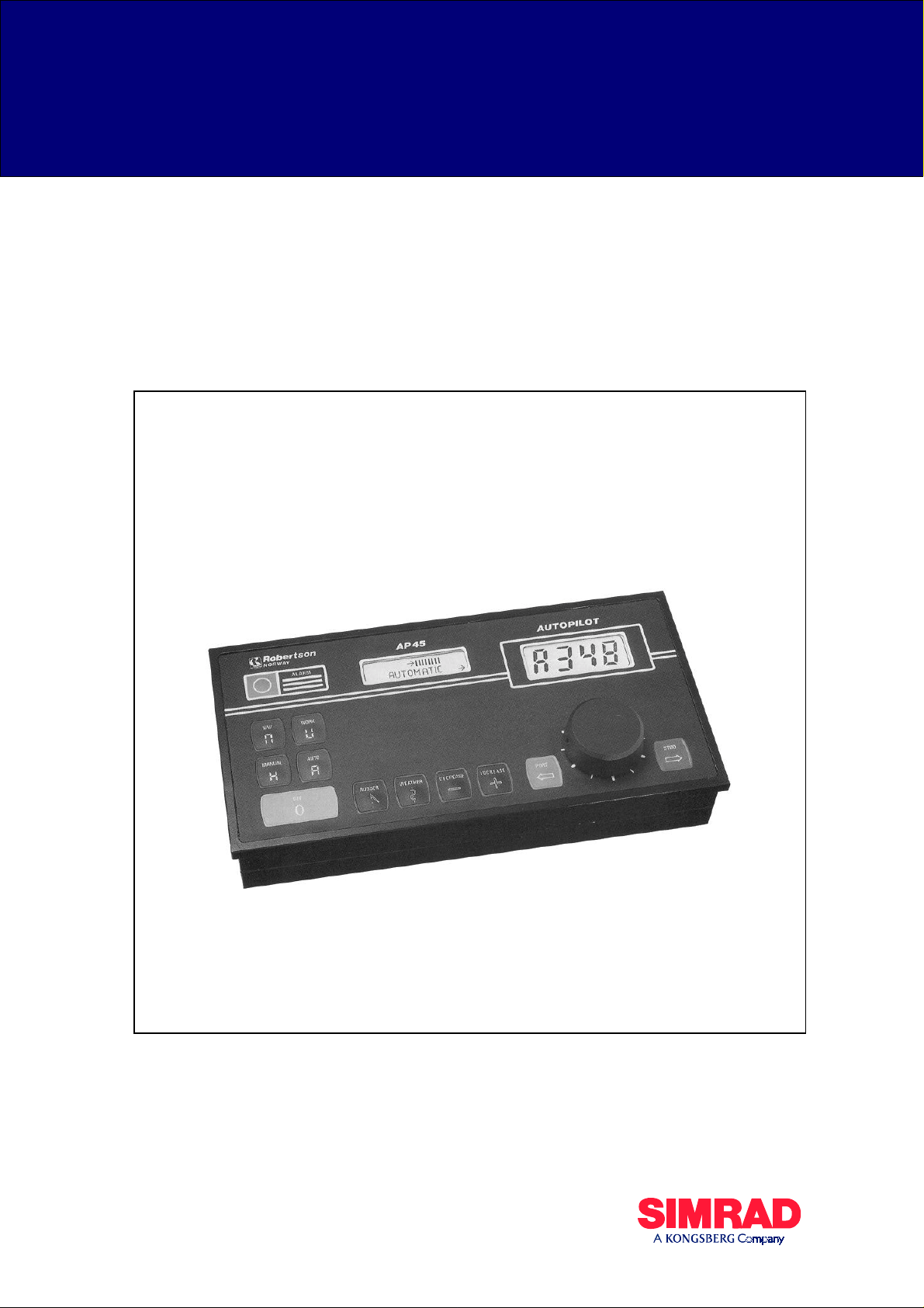
Robertson AP45
Autopilot
20220042/6/02
Page 2

This page is intentionally left blank.
Page 3

NOTE!
Simrad Egersund AS makes every effort to ensure that the information
contained within this document is correct. However, our equipment is
continuously being improved and updated, so we cannot assume liability for
any errors which may occur.
The information contained within this document remains the sole property of
Simrad Egersund AS. No part of this document may be copied or reproduced
in any form or by any means, and the information contained within is not to be
passed on to a third party, without the prior written consent of
Simrad Egersund AS.
Warning
The equipment to which this manual applies must only be used for the
purpose for which it was designed. Improper use or maintenance may
cause damage to the equipment or injury to personnel. The user must
be familiar with the contents of the appropriate manuals before
attempting to operate or work on the equipment.
Simrad Egersund AS disclaims any responsibility for damage or
injury caused by improper installation, use or maintenance of the
equipment.
Simrad Egersund AS Telephone: +47 51 46 20 00
Nyåskaien Telefax: +47 51 46 20 01
P.O. Box 55
N-4379 Egersund, Norway
Page 4

Robertson AP45
Modification record
Rev. Written by Checked by Approved by
MODIFICATION RECORD
Robertson AP45 Autopilot
Document revisions
Date Sign. Date Sign. Date Sign.
January 1996 08.01.96
September 1997 08.09.97
October 1998 01.10.98
September 1999 15.09.99
N.G.
N.G.
N.G.
N.G.
08.01.96
08.09.97
01.10.98
15.09.99
I.K.
I.K.
I.K.
I.K.
08.01.96
08.09.97
01.10.98
15.09.99
Th.H.
Th.H.
Th.H.
Th.H.
June 2002 29.05.02 29.05.02 29.05.02
Document history
Rev. Action/Changes/References
September 1990 Covers the software versions V1R0, V1R1, V1R2 and V1R3. New rudder feedback
RF45 included.
January 1996 Updated to software version V1R4. Major extensions of section 3 and 5. RI40
substitutes RI45. G45 included.
September 1997 Modifications due to improved protection against electro magnetic interference,
page 5-1, 5-2, 5-17 and 8-1. J45A grounding page 5-21. Modification on fig. 5-29.
“Soft start” function included on page 3-6. Corrected number of bushings on page 526 and page 5-28. Missing length group 60-100 ft included on page 6-4. Corrected
text in fig. 6-2. Page 5-33: Switch position 8 and 9 changed to NMEA 0183.
October 1998 Minor corrections on following pages: 2-5, 2-6, 2-11, 2-12, 5-3, 5-8, 5-20, 5-21, 5-31,
5-33, 6-1, 7-1, 7-2, 7-4 and 8-3.
September 1999 RI40 substituted by RI9, RI101 by RI35. RF45 substituted by RF45X. S3
substituted by S35. Removed the NMEA0180, inverse polarity. RFC250 substituted
by RFC35NS. New distributor list.
June 2002 Note on page 5-31 included. New distributor list.
To assist us in making improvements to this manual, we would welcome comments and constructive
criticisms. Please send all such comments, in writing to:
Simrad Egersund AS
Documentation Department
P.O. Box 55,
N-4379 Egersund
Norway
Simrad Robertson AS
Egersund - Norway
Page 5

Robertson AP45
A
Modification record
IMPORTANT!
n autopilot is a very useful navigational aid, but DOES NOT under any
circumstance replace a human navigator.
Do not use automatic steering when:
• In heavy traffic areas or in narrow waters
• In poor visibility or extreme sea conditions
• When in areas where use of autopilot is prohibited by law
When using an autopilot:
• Do not leave the helm unattended
• Do not place any magnetic mat erial or equipment near magnetic or
fluxgate compass used in the autopilot system
Verify at regular intervals course and position of vessel
• Always switch to Standby mode in due time to avoid hazardous situations
Simrad Robertson AS
Egersund - Norway
Page 6

Robertson AP45
Modification record
Simrad Robertson AS
Egersund - Norway
Page 7

Robertson AP45 Autopilot
Table of contents
1. GENERAL INFORMATION..................................................1-1
2. OPERATION OF THE AUTOPILOT...................................2-1
Page I
TABLE OF CONTENTS
Introduction...................................................................................................................1-1
System description.........................................................................................................1-1
AP45 Control Unit.........................................................................................................1-1
Heading Sensors............................................................................................................1-1
Rudder Feedback Units.................................................................................................1-2
Junction units.................................................................................................................1-3
Optional equipment.......................................................................................................1-3
Remote Controls............................................................................................................ 1-3
Rudder Angle Indicators................................................................................................1-4
General..........................................................................................................................2-1
Front Panel ....................................................................................................................2-1
Mode selection ..............................................................................................................2-1
Parameter setting...........................................................................................................2-3
Course selection.............................................................................................................2-4
Navigating with the AP45..............................................................................................2-5
Mixed mode, XTE & CTS.............................................................................................2-5
XTE mode.....................................................................................................................2-6
Steering by bearing to waypoint (CTS).........................................................................2-8
Remote Controls General............................................................................................2-10
F200-40 Remote Control.............................................................................................2-10
S9 Steering Lever........................................................................................................2-11
FU91 Follow up Steering Lever ..................................................................................2-14
Fault warnings.............................................................................................................2-16
3. DESIGN AND THEORY OF OPERATION.........................3-1
Automatic Steering ........................................................................................................3-1
AP45 Control Unit.........................................................................................................3-2
CD109 Course Detector ................................................................................................3-2
Rudder Feedback Units.................................................................................................3-3
RF45X Rudder Feedback Unit......................................................................................3-3
RF14XU Rudder Feedback Unit (optional)...................................................................3-3
Junction Units................................................................................................................3-4
J45S Junction Unit.........................................................................................................3-4
J45A Electronic Junction Unit.......................................................................................3-6
4. TECHNICAL SPECIFICATIONS........................................4-1
AP45 Control Unit.........................................................................................................4-1
CD109 Course Detector ................................................................................................4-2
RFC35NS Fluxgate compass.........................................................................................4-3
G40A Gyro Interface.....................................................................................................4-4
G45 Gyro Interface........................................................................................................4-4
FI100-40 Fluxgate Interface..........................................................................................4-5
RF45X Rudder Feedback Unit......................................................................................4-5
RF14XU Rudder Feedback Unit...................................................................................4-6
J45S Junction Unit.........................................................................................................4-7
J45A Junction Unit........................................................................................................4-7
S9 Steering Lever..........................................................................................................4-8
FU91 Steering Lever.....................................................................................................4-8
S35 Steering Lever........................................................................................................4-9
F1/2 Remote Control...................................................................................................4-10
F200-40 Remote Control.............................................................................................4-10
RI35 Rudder Angle Indicator ......................................................................................4-11
Simrad Robertson AS
Egersund - Norway
Page 8

Page II Robertson AP45 Autopilot
Table of contents
RI9 Rudder Angle Indicator ........................................................................................4-12
5. INSTALLATION.....................................................................5-1
Unpacking and handling................................................................................................5-1
General..........................................................................................................................5-1
AP45 Control Unit.........................................................................................................5-1
Connector assemble.......................................................................................................5-2
Heading sensors.............................................................................................................5-4
General..........................................................................................................................5-4
Magnetic compass.........................................................................................................5-4
RFC35NS Fluxgate Compass........................................................................................5-6
Mounting.......................................................................................................................5-6
Connection.....................................................................................................................5-7
Calibration.....................................................................................................................5-7
Alignment......................................................................................................................5-8
FI100-40 Fluxgate Interface..........................................................................................5-8
G40A Gyro Interface Unit.............................................................................................5-9
G45 Gyro Interface Unit..............................................................................................5-11
RGC Signal Interface Unit...........................................................................................5-12
RF45X Rudder Feedback Unit....................................................................................5-13
RF14XU Rudder Feedback Unit.................................................................................5-14
J45S Junction Unit.......................................................................................................5-19
J45A Junction Unit......................................................................................................5-21
Optional equipment.....................................................................................................5-26
F200-40 Remote Control.............................................................................................5-26
S9 Steering Lever........................................................................................................5-26
FU91 Steering Lever...................................................................................................5-28
F1/2 Remote Control...................................................................................................5-30
S35 Steering Lever......................................................................................................5-30
RI9 Rudder Angle Indicator ........................................................................................5-31
RI35 Rudder Angle Indicator ......................................................................................5-33
Panel mounting............................................................................................................5-34
Bracket mounting........................................................................................................5-34
Illumination.................................................................................................................5-35
Zero adjust...................................................................................................................5-35
Reversed deflection.....................................................................................................5-35
Connection to Navigation Receiver.............................................................................5-36
Watch alarm ................................................................................................................5-37
6. START-UP PROCEDURE/ COMMISSIONING.................6-1
Power ON......................................................................................................................6-1
Rudder Feedback Adjustment........................................................................................6-1
Direction of Rudder Movement.....................................................................................6-1
Rudder speed.................................................................................................................6-2
Course Detector Alignment...........................................................................................6-2
Selection of parameter settings......................................................................................6-2
Select language..............................................................................................................6-3
Type of Heading Sensor................................................................................................ 6-4
Off Course limit.............................................................................................................6-4
Vessel's length............................................................................................................... 6 -4
Counter rudder...............................................................................................................6-5
Rudder limit...................................................................................................................6-5
Rudder deadband...........................................................................................................6-5
NMEA-format...............................................................................................................6-5
Disengage of autotrim-function in WORK-mode..........................................................6-5
Disengage of Off Course alarm in Work mode .............................................................6-6
Sea Trial ........................................................................................................................6-6
Simrad Robertson AS
Egersund - Norway
Page 9

Robertson AP45 Autopilot
Table of contents
7. TROUBLE SHOOTING .........................................................7-1
8. SPARE PARTS AND DRAWINGS.......................................8-1
9. SALES AND SERVICE WORLDWIDE (990901)...................9-1
Page III
Fault warnings...............................................................................................................7-1
Debug/Adjust mode.......................................................................................................7-5
AP45 Control Unit.........................................................................................................8-1
CD109 Course Detector ................................................................................................8-4
G40A Gyro Interface.....................................................................................................8-5
G45 Gyro Interface........................................................................................................8-7
FI100-40 Fluxgate Interface..........................................................................................8-9
RF45X Rudder Feedback..............................................................................................8-9
RF14XU Rudder Feedback Unit...................................................................................8-9
J45S Junction Unit.......................................................................................................8-10
J45A Junction Unit......................................................................................................8-12
F200-40 Remote Control.............................................................................................8-14
S9 Steering Lever........................................................................................................8-16
S35 Steering Lever......................................................................................................8-16
FU91 Steering Lever...................................................................................................8-16
RI9 Rudder Angle Indicator ........................................................................................8-17
RI35 Rudder Angle Indicator ......................................................................................8-17
LIST OF DRAWINGS
FIG. 1-1 AP45 SYSTEM LAYOUT - BASIC SYSTEM WITH OPTIONS ................................1-1
F
IG. 2-1 AP45 CONTROL UNIT - FRONT PANEL...........................................................2-1
F
IG. 3-1 AUTOPILOT PRINCIPLE DIAGRAM...................................................................3-1
F
IG. 3-2 PROCESSOR CONTROLLED AUTOPILO T ...........................................................3-1
F
IG. 3-3 COURSE DETECTOR PRINCIPLE......................................................................3-2
F
IG. 3-4 RF45X PRINCIPLE .........................................................................................3-3
F
IG. 3-5 BASIC SYSTEM................................................................................................3-4
F
IG. 3-6 SOLENOIDS WITH POSITIVE COMMON ............................................................3-5
F
IG. 3-7 SOLENOIDS WITH NEGATIVE COMMON...........................................................3-5
F
IG. 3-8 J45A PRINCIPLE ............................................................................................3-6
F
IG. 4-1 AP45 CONTROL UNIT - DIMENSIONS.............................................................4-1
F
IG. 4-2 CD109 COURSE DETECTOR............................................................................4-2
F
IG. 4-3 RFC35NS - DIMENSIONS ..............................................................................4-3
F
IG. 4-4 G40A GYRO INTERFACE - DIMENSIONS.........................................................4-4
F
IG. 4-5 FI100-40 FLUXGATE INTERFACE - DIMENSIONS ...........................................4-5
F
IG. 4-6 RF45X RUDDER FEEDBACK - DIMENSIONS...................................................4-5
F
IG. 4-7 RF14XU RUDDER FEEDBACK UNIT - DIMENSIONS........................................4-6
F
IG. 4-8 J45S/J45A/G45 - DIMENSIONS .....................................................................4-7
F
IG. 4-9 S9 STEERING LEVER - DIMENSIONS ..............................................................4-8
F
IG. 4-10 FU91 STEERING LEVER - DIMENSIONS.......................................................4-8
F
IG. 4-11 S35 STEERING LEVER - DIMENSIONS ..........................................................4-9
F
IG. 4-12 F1/2 REMOTE CONTROL - DIMENSIONS.....................................................4-10
F
IG. 4-13 F200-40 REMOTE CONTROL DIMENSIONS.................................................4-10
F
IG. 4-14 RI35 RUDDER ANGLE INDICATOR - DIMENSIONS......................................4-11
F
IG. 4-15 RI9 RUDDER ANGLE INDICATOR - DIMENSIONS........................................4-12
F
IG. 5-1 AP45 CONTROL UNIT - PANEL MOUNT .........................................................5-1
F
IG. 5-2 AP45 CONTROL UNIT - BRACKET MOUNTING ...............................................5-1
F
IG. 5-3 CONTROL UNIT - CONNECTOR MOUNTING......................................................5-2
F
IG. 5-4 AP45 EXTERNAL CABLING DIAGRAM .............................................................5-3
F
IG. 5-5 CD109 COURSE DETECTOR - MOUNTING ......................................................5-5
F
IG. 5-6 AP45/RFC35NS - CONNECTION...................................................................5-7
F
IG. 5-7 RFC35NS - INTERNAL CONNECTION ...........................................................5-7
Simrad Robertson AS
Egersund - Norway
Page 10

Page IV Robertson AP45 Autopilot
Table of contents
FIG. 5-8 AP45/FI100-40 FLUXGATE INTERFACE - WIRING.........................................5-8
F
IG. 5-9 G40A GYRO INTERFACE CONNECTIONS........................................................5-9
F
IG. 5-10 G40A PC-BOARD - SWITCH LOCATION.......................................................5-10
F
IG. 5-11 CONNECTION TO G45 EXCITATED SYNCHRO TRANSMITTER.......................5-11
F
IG. 5-12 CONNECTION TO GYRO EXCITATED SYNCH RO T RANSMITTERS ...................5-11
F
IG. 5-13 G45 INPUT/OUTPUT...................................................................................5-12
F
IG. 5-14 AP45/RGC SIGNAL INTERFACE UNIT - WIRING........................................5-12
F
IG. 5-16 RF45X RUDDER FEEDBACK UNIT - MOUNTING........................................5-13
F
IG. 5-17 RF14XU - MOUNTING...............................................................................5-14
F
IG. 5-18 RF45 TEMPLATE SCALE 1:1 ......................................................................5-15
F
IG. 5-19 SCREEN TERMINATION...............................................................................5-17
F
IG. 5-20 RF14XU INTERNAL WIRING......................................................................5-18
F
IG. 5-21 RF14XU/J45S - WIRING ...........................................................................5-19
F
IG. 5-22 J45A JUNCTION UNIT GROUNDING...........................................................5-21
F
IG. 5-23 AP45 WIRING DIAGRAM - BASIC SYSTEM (015936H).................................5-22
F
IG. 5-24 AP45 WIRING DIAGRAM - SOLENOIDS WITH POSITIVE COMMON (015936H)5-23
F
IG. 5-25 AP45 WIRING DIAGRAM - SOLENOIDS WITH NEGATIVE COMMON (015936H)5-24
F
IG. 5-26 AP45/J45 WIRING DIAGRAM......................................................................5-25
F
IG. 5-27 F200-40/AP45 - WIRING DIAGRAM............................................................5-26
F
IG. 5-28 S9 MOUNTING ...........................................................................................5-26
F
IG. 5-29 S9/AP45 - WIRING DIAGRAM .....................................................................5-27
F
IG. 5-30 S9 STEERING LEVER - INTERNAL WIRING..................................................5-27
F
IG. 5-31 FU91 MOUNTING ......................................................................................5-28
F
IG. 5-32 FU91 WITHOUT MODE SWITCHING ............................................................5-28
F
IG. 5-33 FU91 WITH MODE SWITCHING...................................................................5-29
F
IG. 5-34 FU91 MULTIPLE INSTALLATION................................................................5-29
F
IG. 5-35 S35, F1/2 - AP45 - WIRING DIAGRAM........................................................5-30
F
IG. 5-36 AP45 WIRING DIAGRAM - J3 W/MULTIPLE INPUT......................................5-30
F
IG. 5-37 RI9 WIRING DIAGRAM................................................................................5-31
F
IG. 5-38 RI9 INPUT SIGNAL SELECTION ..................................................................5-32
F
IG. 5-39 RI35-J45A WIRING DIAGRAM...................................................................5-33
F
IG. 5-40 RI35-J45S WIRING DIAGRAM ...................................................................5-33
F
IG. 5-41 PANEL MOUNTING......................................................................................5-34
F
IG. 5-42 RI35 BRACKET MOUNTING .......................................................................5-34
F
IG. 5-43 N40 NAV. INTERFACE MOUNTING (FOR MAIN PCBS WITH REVISION UP TO
AND INCLUDING REVISION
F
IG. 5-44 AP45/NAVIGATION RECEIVER - WIRING ....................................................5-37
F
IG. 5-45 WA9 CIRCUIT/WIRING DIAGRAM ...............................................................5-37
F
IG. 6-1 AP45 INSTALLATION LOOP............................................................................6-3
F
IG. 6-2 COUNTER RUDDER SETTINGS.........................................................................6-7
F
IG. 8-1 AP45 EXPLODED VIEW ..................................................................................8-2
F
IG. 8-2 AP45 SIGNAL REFERENCE.............................................................................8-3
F
IG. 8-3 CD109 - SPARE PARTS...................................................................................8-4
F
IG. 8-4 G40A COMPONENT REFEREN CE ....................................................................8-5
F
IG. 8-5 G40A CIRCUIT DIAGRAM ...............................................................................8-6
F
IG. 8-6 G45 COMPONENT REFEREN CE.......................................................................8-7
F
IG. 8-7 G45 CIRCUIT DIAGRAM..................................................................................8-8
F
IG. 8-8 RF14XU - SPARE PARTS................................................................................8-9
F
IG. 8-9 J45S COMPONENT REFERENCE...................................................................8-10
F
IG. 8-10 J45S CIRCUIT DIAGRAM.............................................................................8-11
F
IG. 8-11 J45A COMPONENT REFERENCE.................................................................8-12
F
IG. 8-12 J45A CIRCUIT DIAGRAM ............................................................................8-13
F
IG. 8-13 F200-40 COMPONENT REFEREN CE............................................................8-14
F
IG. 8-14 F200-40 CIRCUIT DIAGRAM .......................................................................8-15
F
IG. 8-15 RI40 EXPLODED VIEW ...............................................................................8-17
G).............................................................................5-36
Simrad Robertson AS
Egersund - Norway
Page 11
Robertson AP45 Autopilot
General Information
Page 1-1
1. GENERAL INFORMATION
Introduction
System descriptio n
Today Simrad manuf acture a comple te range of au topilots for all types o f vessels,
from leisure bo ats up to advanced steer ing systems for merch ant marine vessels.
Our factory for these products – branded Robertson – is located in Egersund, on
the south/west coast of Norway. The comp any’s inv olve men t in autop ilots beg an in
1953 with equipment for the North Sea fishing fleet.
In 1982 the world's first microprocessor based autopilot, the Robertson AP100, was
introduced and shortly after the AP9 and AP40 systems followed.
The AP45 autopilot described in this document is based on the experience with the
AP40 and the AP9 models. A series of improvements based upon this experience
has been implemented in the new model and special attention has been paid to
simplified operation.
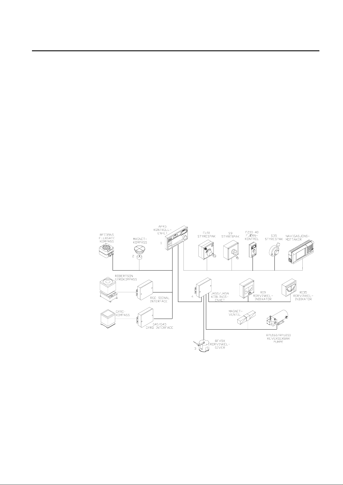
The standard AP45 system consists of the following units (refer to Fig. 1-1):
1. AP45 Control Unit with accessories
2. Heading sensor
3. Rudder Feedback Unit with transmission link
4. Junction Unit
AP45 Control Unit
Heading Sensors
Fig. 1-1
AP45 System layout - Basic system with options
All settings and operation of the autopilot take place on the control unit. In
addition to push bu ttons it has two LCD-displays and a cou rse selector knob on
the front panel. The control unit is made of seawater resistant aluminium and has
a polyester coating to protect it against the environment. The main electronics are
located in the control unit, and connection to other system components are by high
quality connectors to facilitate reliability and easy maintenance.
The AP45 autopilot can be used with one of three different types of heading
sensors:
Simrad Robertson AS
Egersund - Norway
Page 12

Page 1-2 Robertson AP45 Autopilot
General Information
1. Magnetic compass with CD109 Course Detector
2. RFC35NS Fluxgate compass*
3. Gyrocompass (using optional G40A or G45 Interface Unit)
*) For other types of Fluxgate Compass the FI100-40 Fluxgate Interface must be
used.
CD109 Course Detector
CD109 is a magnetic sensor in moulde d plastic which is mounted on the vesse l's
magnetic compass to transfer the heading to the control unit.
RFC35NS Fluxgate Compass
This is an electronic sense unit with NMEA- and sine/cosine output. The compass
has a 0,3 m ”pigtail” cable. RFC35NS substitutes the RFC250 Fluxgate compass.
RFC250 cable (P/N 20183554) is necessary at new installations.
G40A/G45 Gyro Interface Unit
The gyro interface unit is connected between the AP45 and a gyro compass. It
utilises the repeater sign al outpu t from the gy ro co mpass to g enerate a sine/co sine
heading signal for the autopilot.
G40A to be used with stepper or geared synchro signal. G45 to be used with
synchro 1:1 signal.
Rudder Feedback Units
FI100-40 Fluxgate Interface
FI100-40 is an interface unit to be co nnected betw een the AP45 and an e lectronic
fluxgate compass with sine/cosine output, e.g. VDO, Marinex, Sowester, Brooks &
Gatehouse.
RF45X Rudder Feedback Unit
This unit transmits two electrical signals proportional to the rudder angle. One
signal operates as a feedback for the autopilot, the other as drive signal for rudder
angle indicators. The unit is mounted close to the rudder stock and is mechanically
connected to the rudder by the T45 Transmission link.
RF14XU Rudder Feedback Unit
This unit can replace the RF45 Rudder Feedback Unit in installations where a
more rugged construction of the feedback unit is preferred. Besides electronic
circuitry to generate feedback signals for the autopilot and rudder angle indicators
it has been provided with 2 sets of limit switches. RF14XU can not drive the RI101
Rudder Angle Indicator, but all other types of Robertson indicators.
Simrad Robertson AS
Egersund - Norway
Page 13

Robertson AP45 Autopilot
General Information
Page 1-3
Junction units
Optional equipment
Remote Controls
Except for a bigger cabinet, the J45S and the J45A junction un its describe d in this
manual are identical to the previous versions, J200S-40 and J101A-40
respectively.
J45S Junction unit
The J45S Junction Unit will operate continuously running hydraulic power units
with directional valves as Robertson RPU3 or similar. The unit contains a printed
circuit board with terminal block, fuse, galvanic isolated solid state output to
switch the solenoids and start relay for the Power Unit. All mounted in an
aluminium cabinet with polyester coating.
J45A Electronic Junction Unit
The unit provides variable speed control of reversible hydraulic power units (e.g.
Robertson RPU80, RPU100 RPU160 or RPU200) and mechanical power units
(MRD100 or HLD2000). The unit consists of a prin ted circuit board with termin al
block, fuse and drive electronics, mounted in the same type of aluminium cabinet
as the J45S.
A series of options are available for the basic AP45 system.
S9 Non-follow-up (NFU) steering lever
S9 is a splash proof steering lever for bulkhead or console mounting. The unit is
constructed of a machined alum inium housing. The intern al mechanism of the S9
permits locking of the lever in the mid-position to avoid inadvertent operation.
When connected to the AP45, the S9 can also be used to switch the mode of the
autopilot when the lever is pulled out or pushed in.
FU91 Follow-Up (FU) steering lever
FU91 is a splash proof steering lever for bulkhead or console mounting. The unit
has a 45-0-45 degrees dial and a Push to take command bu tton. By positio ning th e
lever, a desired rudder angle can be set without using a rudder angle indicator.
Dimensions and design are the same as the S9, and it has a mid-position detent.
S35 Non Follow Up (NFU) Steering Lever
S35 is designed for indoor and outdoor bulkhead mounting. The lever is spring
loaded to midposition. It also has a “Mode” button that is not used when connected
to AP45.
F1/2 Remote Control (NFU)
F1/2 is a handheld control for push button steering, fitted w ith a rubber grip. It is
made of cast seawater resistant aluminium and fitted with a 10 meter (30 ft.)
cable.
F200-40 Remote Control
F200-40 is a multifunction hand he ld remote control with a 4-digit LCD display
and a course sele ctor knob to set course or rudder angle . It has push bu ttons for
power steering, course adjustment and mode selection between power steering,
dodging and auto steering. The unit consists of a PC board moun ted in a splash
proof aluminium cabinet fitted with a 7m (23 ft) cable connecting to the control
unit.
Simrad Robertson AS
Egersund - Norway
Page 14

Page 1-4 Robertson AP45 Autopilot
General Information
Rudder Angle Indicators
RI9 Rudder Angle Indicator
RI9 is an analogue indicator showing the rudder position at angles up to 45
degrees on each side of midship position. The scaling is 2 degrees pr. division.
The scale illumination is adjustable by a knob on the front.
The housing is constructed of painted aluminium inte nded for e ither bulkhead o r
console mounting. The splash proof construction is suitable for exposed mounting
locations.
RI35 Rudder Angle Indicator
RI35 is an analogue indicator showing the rudder position at angles up to 45
degrees on each side of midship position. The scaling is five degrees pr. division.
A front panel key is used for rudder zero adjustment and illumination adjustment.
The splash proof construction allows panel, bulkhead or bracket mounting in
exposed locations, such as b rid ge wings as wel l a s wheel hous e and engi ne room.
RI35 is delivered with a 20 meter (65 feet) cable.
Simrad Robertson AS
Egersund - Norway
Page 15
Robertson AP45 Autopilot
Operation
General
Page 2-1
2. OPERATION OF THE AUTOPILOT
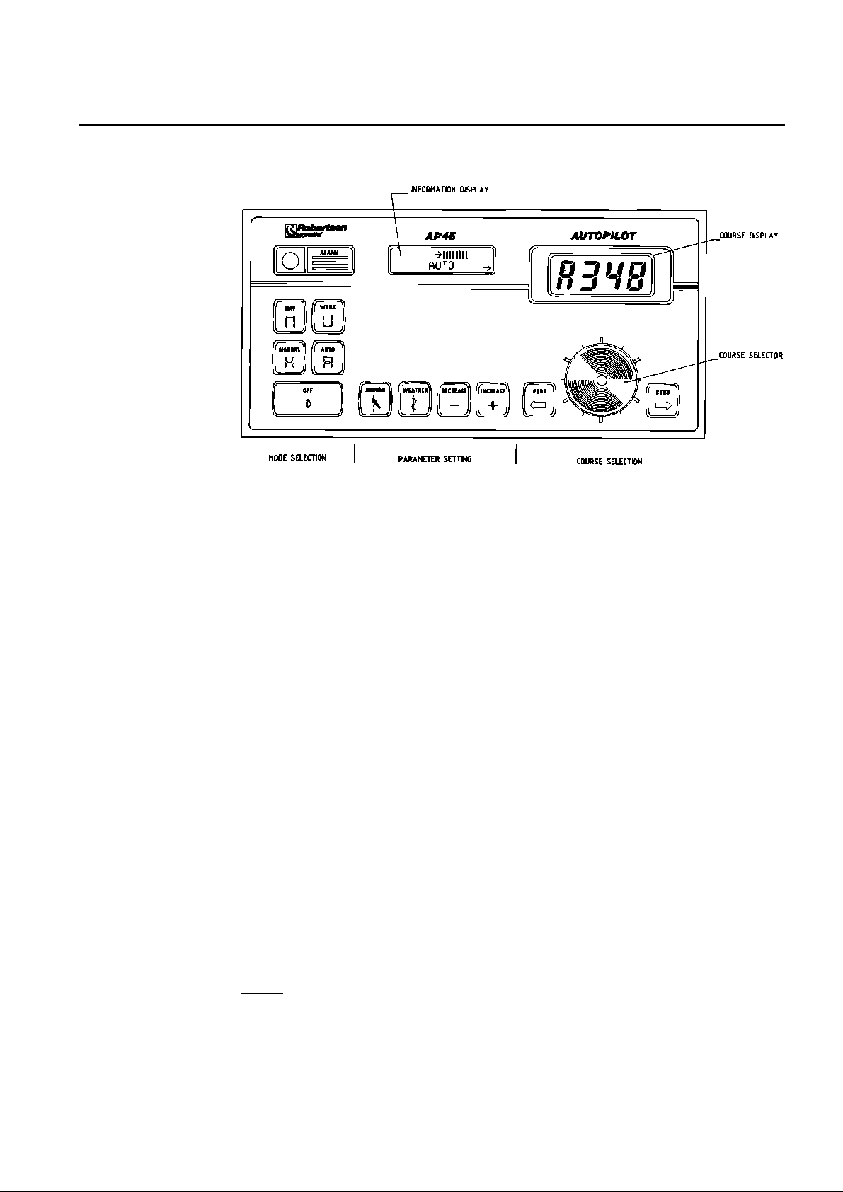
Fig. 2-1
AP45 Control Unit - front panel
Front Panel
Mode selection
AP45 autopilot is operated by means of keypad push buttons on the front panel. To
facilitate operation, the buttons are marked with text and symbo ls. The buttons
are backlighted, activated mode buttons being brighter than the others.
Course selection is made by the rotary Cou rse Selecto r Knob . Course adjustme nts
in steps of one degree can be achieved by the port or starboard push b u ttons.
The front panel has two LCD d isplays, referred to as the information disp lay (left
side) and the course display (right side). An alarm buzzer and an alarm reset
button is also on the front panel.
A few simple operations like pressing a button and/or turning the Course Selector
Knob is required in ordin ary use of the autopilot. All other instructions and data
required for the operation is stored in the autopilot at delivery from Robertson.
The front panel can be divided into three sections: Mode selection, Parameter
setting and Course selection.
Together with th e OFF-button and the 4 m ode buttons, this section also contains
an alarm buzzer and ALARM RESET-button.
MANUAL
The MANUAL button serves two purposes. It switches on the autopilot and selects
manual steering mode. In this mode the Course Display gives a digital readout of
compass heading, while the vessel can be steered manually by helm or steering
lever(s).
AUTO
The AUTO-mode is used under normal conditions when the boat is steered
automatically on a preset course.
When the AUTO-button is pressed, the autopilot selects the current vessel
heading as "course to steer".
Simrad Robertson AS
Egersund - Norway
Page 16

Page 2-2 Robertson AP45 Autopilot
Operation
Any difference betwe en co ur se to ste er and the v e ssel's actu al he ad ing w ill the n be
shown as a bargraph in the Information Display. One bar equals one degree.
Rudder commands are indicated by an arrow in the lower left or right corner of
the information display de pending upon which direction th e autopilot commands
the rudder to move.
WORK
The WORK-mode is an automatic mode to be used under operational conditions
different from those normally found when a vessel is under motor power on a
preset course. Examples are trawling, towing, sailing, slow speed etc.
In WORK-mode the PORT- and STBD-buttons can be used for immediate rudder
off-set (trim) if necessary. This manual off-set compensates for the built-in
autotrim which needs time to b uild up the appropriate off-set.
The Information Display shows the off-set value when the PORT- or STBD button
is pressed.
Boats under sail power and some trawlers may need a rudder off-set when steered
by hand. To avoid cancellation of the rudder off-set when changing to automatic
steering, the WORK-mode can be selected directly from MANUAL-mode. The
rudder off-set is then maintained as "on course" reference. This off-set is also
maintained when changing from WORK to NAV mode.
If the AUTO-mode is selected from MANUAL-mode, the rudder is first taken to
midposition before a sufficient off-set of the rudder is built-up automatically
(autotrim).
A different RUDDER value may be preferred in WORK-mode as compared to that
in AUTO-mode. The WORK-mode value will be stored in the AP45 memory for
later use.
Note!
Pair-trawling that requires manual trim only, will also require that the autotrim
be disabled. Refer to “Disengage of autotrim-function in WORK-mode”, page 6-5,
for specific details.
NAV
NAV-mode is used when a navigation receiver is connected to the autopilot for
automatic waypoint steering. To be able to use the NAV-mode with older AP45
(below s.n. 4000), the main PCB must be equipped with the N40 Navigation
Interface.
When the NAV-mode is selected, the AP45 automatically monitors the signals
from the navigation system. If the signals are absent or in a different format than
the data format selected in the AP45, an alarm w ill be given to ale rt the operato r.
See “Navigating with the AP45” page 2-5.
OFF
The autopilot is switched off by pressing the OFF-button for 2 seconds, during
which time the alarm will sound. Th e alarm cease s when th e AP45 is switch ed of f.
If the OFF-button is released before two seconds have elapsed, the auto pilot will
continue to operate as before and the alarm signal is automatically reset.
Rudder commands will stop as long as the OFF-button is pressed. All pre-set
parameters in the autopilot are stored while the unit is switched off.
Simrad Robertson AS
Egersund - Norway
Page 17

Robertson AP45 Autopilot
Operation
ALARM
The acoustic alarm is reset by pressing the red alarm push button.
Alarm messages shown on the information display are described under “Fault
warnings”, page 2-16.
Page 2-3
Parameter setting
General
The middle section of the AP45 control unit contains 4 push buttons and an
Information Di splay. The display sho ws selected mod e, deviation f rom set co urse,
parameter settings and other user information. When RUDDER or WEATHER
buttons are pressed, the display shows which button has been activated and to
what level the value has bee n set by th e n um be r of bars as w ell as in pl ain f igu re s.
The display returns to normal read-out, showing the selected mode one minute
after the last press on one of the buttons.
The text in the Information Display can be in one of five selectable languages:
English, French, German, Spanish and Norwegian (see “Select language”, page 6-
3.
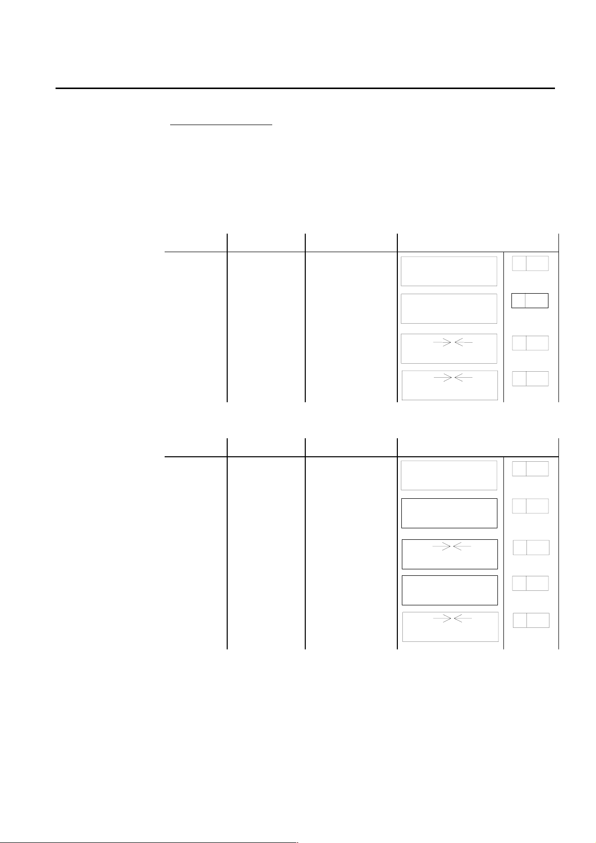
Turn on
Turn on the AP45 by pressing the MANUAL button. The information display will
show for approx. three seconds:
SOFTWARE V_R_
MANUAL
Then it switches to:
NON FOLLOW UP
MANUAL
If the autopilot is connected to and set up for a g yrocompass with g eared synchro
or stepper signal, the display will show at turn on:
GYROADJUST
PRESS +/-
Use the + or - butto n until the autopilot display shows th e same heading as the
gyrocompass.
Then press the MANUAL button and the display will again show:
NON FOLLOW UP
MANUAL
When clear of obstacles and in open waters, steer your vessel on course and press
the AUTO button.
The display will now show:
→←
AUTOMATIC
and the autopilot will automatically keep your vessel on course.
INCREASE and DECREASE
Simrad Robertson AS
Egersund - Norway
Page 18
Page 2-4 Robertson AP45 Autopilot
A
Operation
These buttons are used to alter vario us settings. Each time one button is pr essed,
the value shown on the Informatio n Display, will increase (+) or decre ase (—) by
one unit. The value is also shown as a graphical bar. If a button is pressed for
more than two seconds, the value will auto matically increase or decrease u ntil the
button is released.
RUDDER
When the RUDDER button is pressed, the Information Display shows selected
RUDDER value. The RUDDER value sets the ratio between rudder angle and
heading error (p-factor).
Example: If RUDDER is set to 1.0 and there is a heading error of 2 degrees, the
rudder angle will be 2 degrees. (Heading error x RUDDER value = rudder angle).
The correct RUDDER setting is dependant upon the size and speed of the vessel.
The RUDDER value should increase with decreasing speed.
RUDDER should be set separately in WORK-mode, to optimise the autopilot
performance.
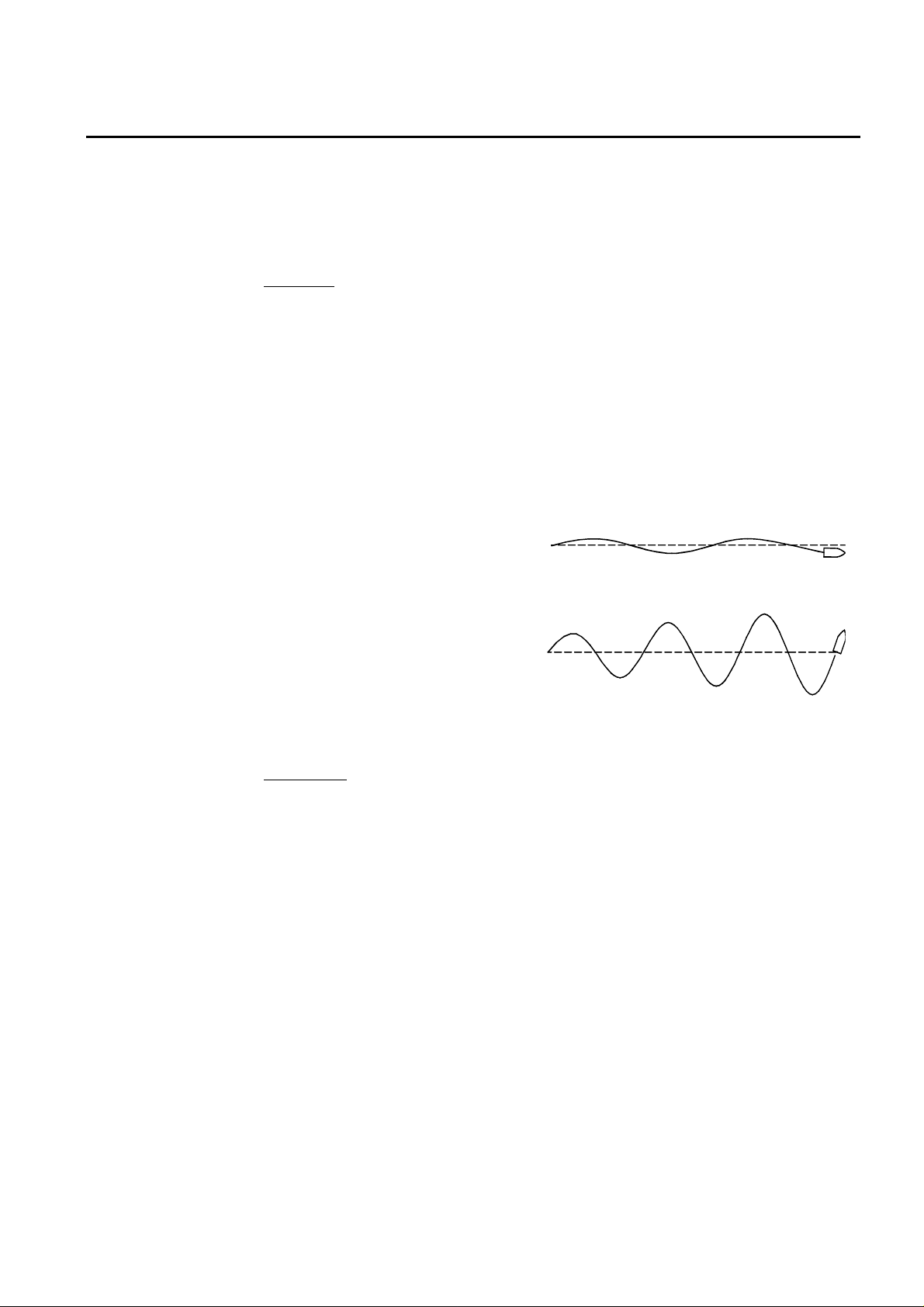
Examples of incorrect RUDDER settings:
A value which is too low gives
relatively large and slo w oscillations
(s-ing) around set course, and several
rudder commands are given in the
same direction before the vessel is
back on course.
Course selection
A value which is too high will give
quick and in worst case increasing
B
oscillations (s-ing) around set course.
The correct setting of RUDDER will be app ro ximate ly in th e mid dle o f th e se tting s
described in A and B above.
WEATHER
The WEATHER setting determines the amount of degrees the vessel may fall off
the set course before any response is given from the rudder. In calm weather it
should be set to OFF which means that theoretically the autopilot allows no
deviation from set course. The WEATHER value should be increased with
increasing sea state.
In conditions where active steering is requ ired, (e.g. following sea condition) , the
value should be reduced.
The course selection section on the au topilot consists of a course d isplay, a cou rse
selector knob and two course adjustment buttons, PORT and STBD.
The Course Display gives a readout of actual ships heading in MANUAL-mode
and set course in AUTO-, WORK- and NAV-mode. The selected mode is also
shown to the left on the display by the same letter as on the mode buttons.
The course selector knob is used for major course changes in AUTO- and WORKmode. To activate the knob it must be pressed down, released, and then turned.
Clockwise turns gives a starboard cou rse chan ge and vice v ersa. O ne re vo lu tion on
the course selector knob is equal to a 60 degree course change. If the knob is not
turned within 10 seconds, it has to be pressed again.
Simrad Robertson AS
Egersund - Norway
Page 19

Robertson AP45 Autopilot
Operation
The PORT and STBD push buttons are for minor course adjustments, pressed
once gives a one degree course change in the appropriate direction. In WORK-
mode however, the buttons are used for manual rudder trim, and course
changes can therefore only be made by the course selector knob.
Page 2-5
Navigating with the AP45
The AP45 has the capability to use steering information from an external
navigator (GPS, LORAN, Plo tter) to dir ect the boat to a sp ecific w aypo int lo cation,
or through a route of waypoints. In the NAV mode, the AP45 uses the heading
sensor as it's primary source of heading for course keeping. The steering
information received from the external navigator alters the set course to direct the
AP45 to the destination waypoint.
Note!
Navigational steering must only be used in open waters. The process of having an
external navigation receiver direct an autopilot can be a slow acting process. By
selecting the NAV mode, the AP45 is set for automatic steering on the current set
course and then waits for the user to accept the course change to the destination
waypoint.
To obtain satisfactory navigation steering, the following points must be fulfilled
prior to entering the NAV mode:
• The AP45 autosteering must be tested and found satisfactory.
• The navigation receiver must be operating and the navigation system (GPS,
LORAN, Decca) must be in full operating mode with adequate signal
characteristics for valid position and steering data.
• The magnetic compass or Fluxgate must have a minimum of deviation.
• At least one waypoint must be entered and selected as the current waypoint in
the navigation receiver.
Mixed mode, XTE & CTS
The AP45 is from the factory set up to steer in mixed mode operation (CTS &
XTE). This combines the straight steering capability of cross track error (XTE)
steering in conjunction with the turning capability of bearing mode steering (CTS).
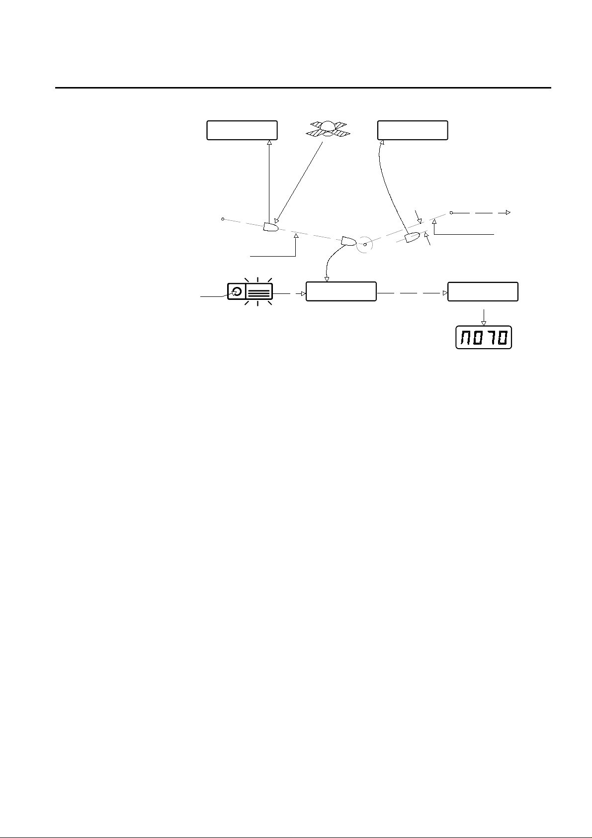
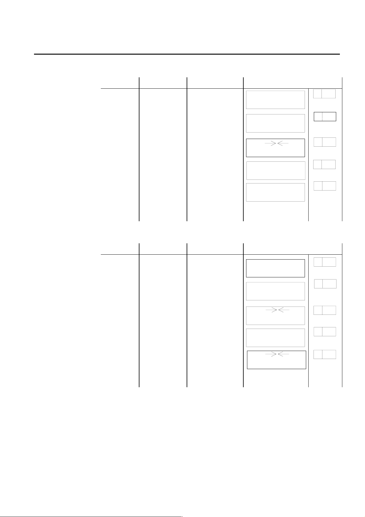
When operating the AP45 in NAV mode to automatically steer through a route of
waypoints, it will steer to th e first waypo int in the route af ter you accept the first
waypoint as the location to steer to. When you arrive at the waypoint, you will
need to verify that the upcoming course change is acceptable. Verification is
performed by pre ssing the Alarm rese t button af ter the ale rt sc re e n is disp lay ed . I f
no verification is received, the AP45 will continue on the current set course in
AUTO mode.
Simrad Robertson AS
Egersund - Norway
Page 20
Page 2-6 Robertson AP45 Autopilot
Operation
GPS satellite
00° ON TRAC K
NAVIGATION
INF O D IS PLA Y
WAYPOINT 1
RESET
Heading =100°
ALARM
WAYPOINT 2
ACCEPT CHANGE?
Y: RESET N: AUTO
INFO DISPLAY
04° XTE =R0.01NM
NAV IGA TION
INFO DISPL AY
XTE
RESET
WAYPOINT 3
New head ing = 70°
10MIN CH G 30°
NAVIGATION
INFO DIS P LAY
COURSE DISPLAY
Note!
Steering through a route of waypoints with the AP45 allows you the total flexibility
for automatic waypoint sequencing, but combines the safety feature of requiring
operator acknowledge for course changes in excess of 10 degrees.
If the AP45 is connected to a Nav. receiver that does not transmit a message with
bearing to next waypoint, it will pick a XTE message and steer on Cross Track
Error only. In that case you have to revert to AUTO mode at each waypoint and
manually change set course to equal bearing to next waypoint and then select NAV
mode again.
XTE mode
When the AP45 steers using cross track error only, it corrects the set course in
order to keep the vessel on a straight track between two waypoints. Bearing
change at waypoints must be made manually by temporarily go to Auto mode change set course - and revert to Nav. mode.
Use the following procedure for XTE steering:
1. Enter the desired bearing line(s) to the Nav. receiver using the present position
and the first waypoint or destination. Distance between waypoints should be of
minimum 2-3 n.m. Otherwise there may not be sufficient time for the system to
calculate the XTE, and fo r the autop ilot to alte r the cour se and bring th e ve ssel
onto the bearing line again.
2. Read the calculated bearing to waypoint from the Nav.receiver.
3. Select AUTO-mode on the AP45 , and set the course to the waypoint showed on
the navigation receiver.
Before going to step 4, ensure that the XTE is within +/- 0.1 n.m. to avoid
hazardous course change when selecting NAV-mode.
4. Select NAV-mode on the AP45. The autopilot now automatically changes the
set course to reduce the Cross Track Error (XTE) to zero. The information
display shows the number of degrees the autopilot has changed the set course,
and the XTE in 1/100's of a nautical mile. Note that the display readout will be
delayed, depending upon the NAV. FILTER setting.
Simrad Robertson AS
Egersund - Norway
Page 21

Robertson AP45 Autopilot
Operation
5. As the vessel gets within the arrival circle set on the navigational receiver, or
Page 2-7
Example:
05° XTE=R 0.02Nm
NAVIGATION
R indicates that the vessel is located to the right of the bearing line, and L
indicates to the left of the bearing line.
00° ON TRACK
NAVIGATION
05° is the number of degrees course correction relative to initial set course. As
the vessel approaches the bearing line, the correction value decreases and
when the vessel is on track, the information display shows:
Note!
The display may show X number of degrees course correction even if it says “ON
TRACK”.
as the vessel passes the perpendicular line to the waypoint, the receiver
transmits a "data not valid" signal to the autopilot. An alarm will then activ ate
and the course to steer will no longer be updated.
To proceed to the next waypoint, the procedure should be repeated from step 2
onwards.
Procedure:
• Reset the alarm on the autopilot and navigational receiver.
• Select “AUTOPILOT” mode on the autopilot
• Use Course Change knob/button s on the autopilot to set the new course given
by the Nav. receiver.
• Press “NAV”
NOTE!
Navigational steering is a slow acting process and the vessel normally follows the
bearing line with a deviation of ±0.02 - 0.03 n.m.(40-50 meters). Higher deviation
may temporarily occur due to rapid change of current, wind, speed or at start-up
from a position off the track line.
05° XTE = R0.02NM
L LEFT
NAVIGATION
INFO D IS P L A Y
05°
BEARING LINE
WAYPOINT 3
00° ON TRACK
NAVIGA T ION
INFO D IS P L AY
WAYPOINT 1
R RIGHT
XTE= R0.02NM
RESET
ALARM
POOR NAVDATA
CHANGE MODE
INFO D IS P LA Y
Simrad Robertson AS
Egersund - Norway
WAYPOINT 2
NAV.RECEIVER
ALARM
Page 22

Page 2-8 Robertson AP45 Autopilot
Operation
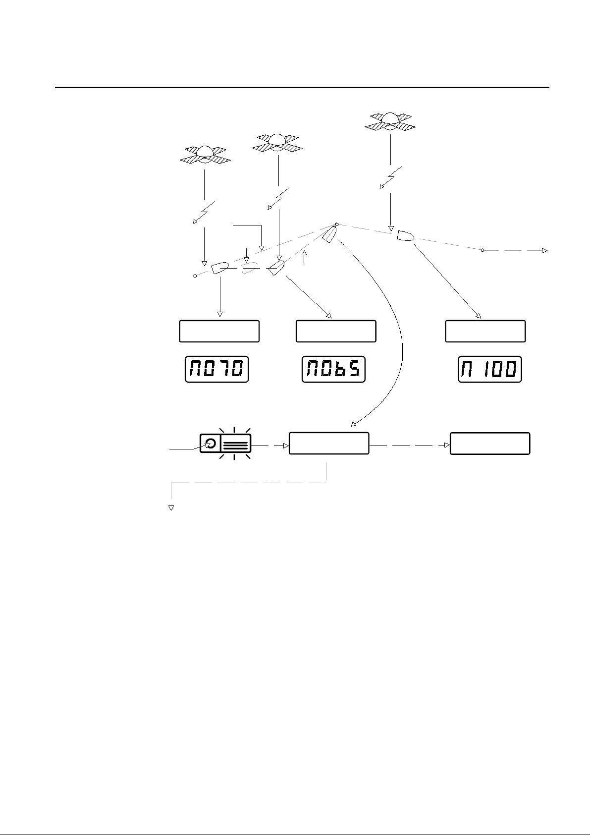
Steering by bearing to waypoint (CTS)
For some navigational receivers, bearing to a waypoint or course to steer is used
as the steering information.
If a satellite navigator is used, it should have compass and log input to ensure
proper dead reckoning between each fix.
1. Set the navigation receiver to calculate bearing to a waypoint from present
position.
2. Select AUTO-mode on the AP45, and set the course selector knob to the bearing
showed on the navigation receiver.
3. Select NAV-mode. The output signals from the navigation receiver will correct
the course to steer to make the vessel steer towards the waypoint.
The Information display shows time since last update and the amount of course
change in degrees, while the course display shows the new course to steer.
08 MIN CHG:05°
NAVIGATION
1. If the corrections from the navigation receiver initiates a course change greater
than 10 degrees, the autopilot alarm is activated and the course change has to
be acknowledged using the ALARM RESET button.
A typical sailing situation is illustrated in figure below.
Simrad Robertson AS
Egersund - Norway
Page 23
Robertson AP45 Autopilot
Operation
WAYPOINT 1
Update
HDG=70°
Drift
Tr a n s it s a te llite s
Update
Page 2-9
Update
WAYPOINT 2
Heading: 100°
WAYPOINT 3
NEW HDG 65°
RESET
08MIN C H G 00°
NAVIGATION
INFO D I SP LA Y
COURSE DISPLAY
ALARM
00MIN CHG 05°
NAVIGATION
INFO DISPLAY INFO DISPLAY
COURSE DISPLAY COURSE DISPLAY
ACCEPT CHANGE?
Y: RESET N: AUTO
INFO D IS P LA Y
RESET
15MIN C H G 00°
NAVIGATION
15MIN C H G 00°
NAVIGATION
Waypoint 2 has been reached. Continue as follows:
• If the heading to next waypoint, showed on the heading display, is accepted,
press RESET.
If not, press AUTOPILOT mode and continue without Nav. Steering
By pressing RESET, the ne w heading is automatically entered and the autopilot
will turn the vessel towards the new heading.
When reaching waypoint 3, repeat the same procedure.
Simrad Robertson AS
Egersund - Norway
Page 24
Page 2-10 Robertson AP45 Autopilot
Operation
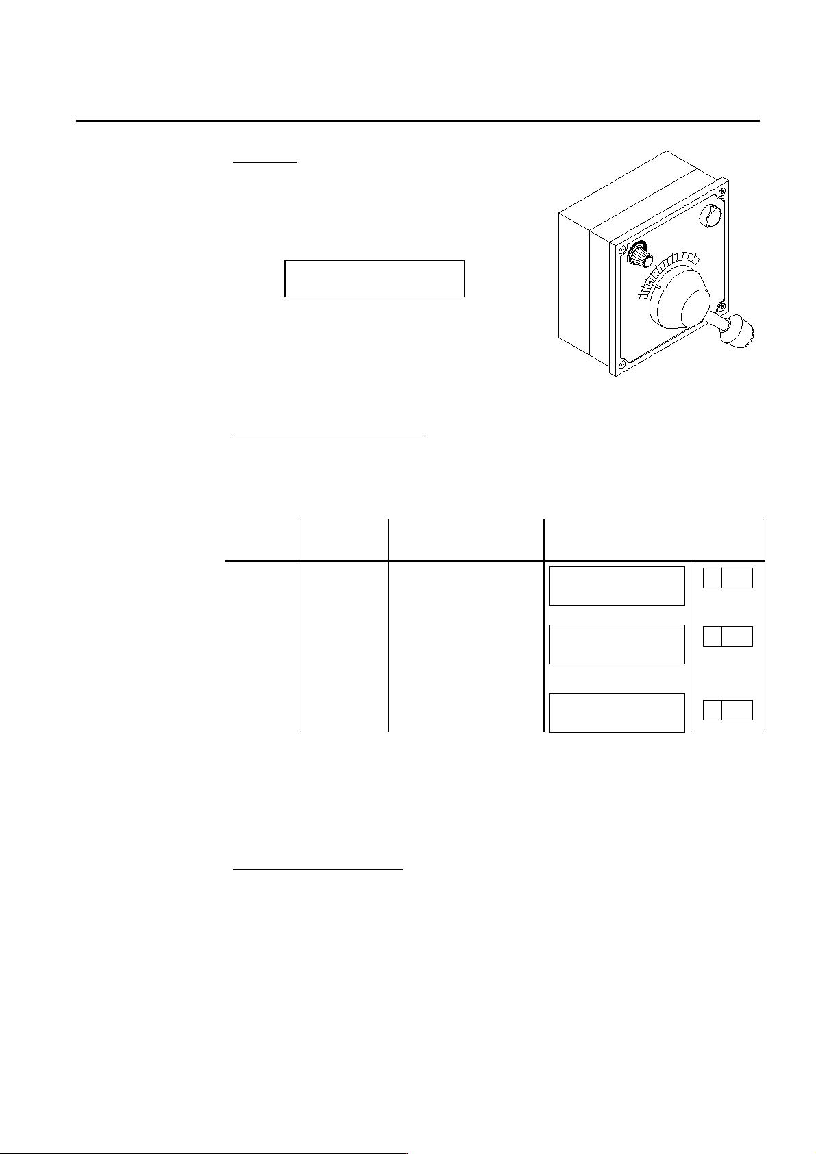
Remote Controls General
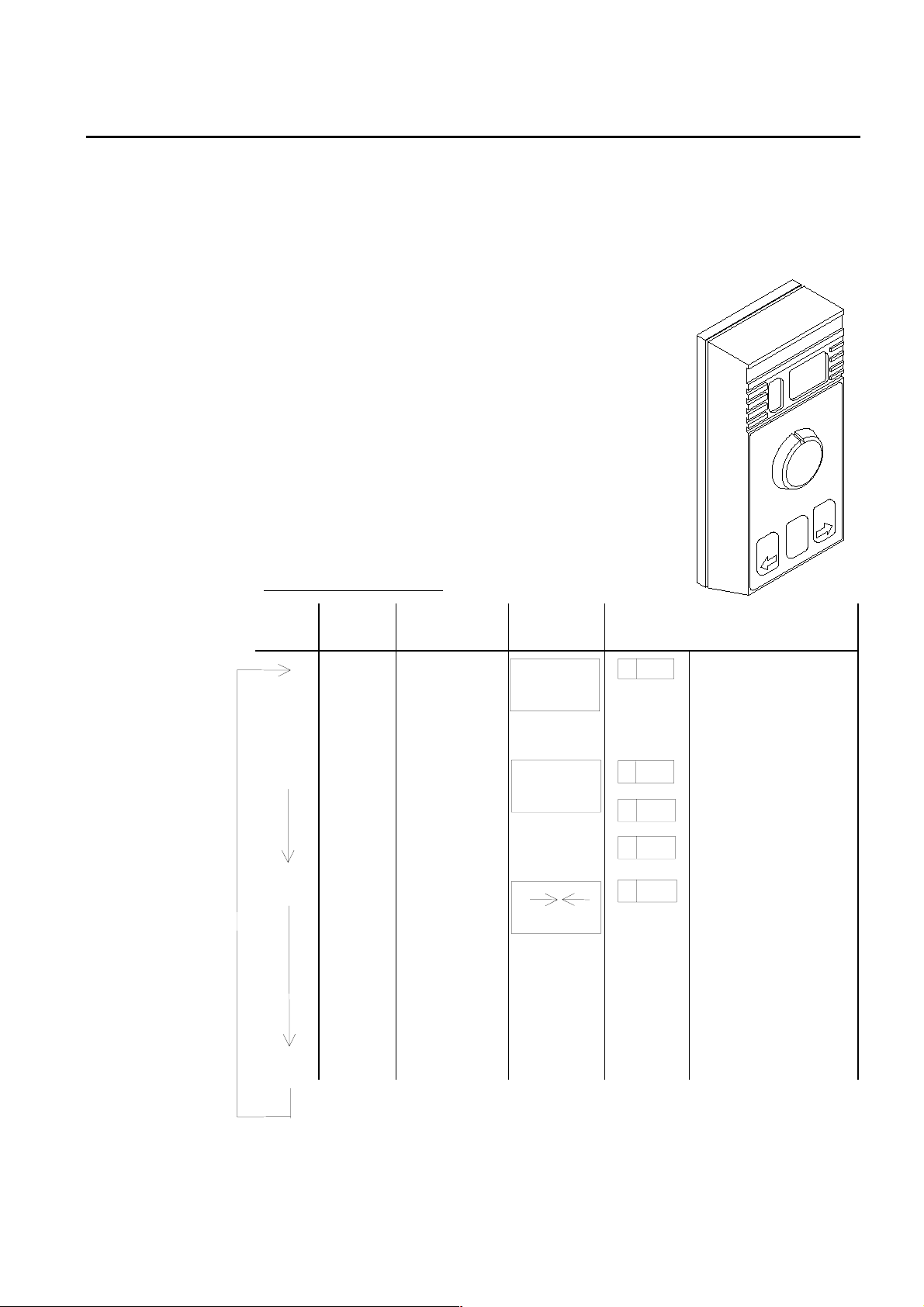
F200-40 Remote Control
The different types of Remote Controls that can be connected to AP45, have
different way of operation, depending on the system configuration.
The F200-40 hand held remo te control makes it possible
to remotely control the AP45 autopilot.
The following control functions are obtainable:
• Display that shows vessel heading or set course like
the course display on the control uni t.
• Course selection by a rotating knob
• Course adjustments by push buttons
• Mode selection
• Manual steering by course selector knob (Follow-Up)
• Manual steering by push buttons (Non-Follow-Up)
Option (selected during installation or sea trial):
• Dodging by means of course selector knob and
automatic return to previous set course.
F200-40 without dodging
Press AP45
Mode
MANUAL
Function AP45
Display
NFU
steering by
F200
NON
FOLLOW UP
MANUAL
F200 Display
H 080 Vessel’s heading
PORT/STBD
push buttons
MODE MANUAL
Follow-Up
steering by
F200 course
selector
F200
FOLLOW UP
MANUAL
F ¯ 00
F
é 04
F
ù 32
Amidships, no
rudder command
4° port rudder
command
32° starboard rudder
command
MODE AUTO
Autosteering
Course set
A 146 Set course
AUTO
by the
AP45/F200
course
selector or
PORT/ STBD
button on
both
MODE
Simrad Robertson AS
Egersund - Norway
Page 25
Robertson AP45 Autopilot
Operation
F200-40 with dodging
Page 2-11
Press AP45
Mode
MANUAL
MODE MANUAL
MODE AUTO
MODE
long
press
MODE
short
press
MODE
Returns
to
MANUAL
AUTO
Function AP45 Display F200 Display
NFU
steering by
NON FOLLOW UP
MANUAL
H 080 Vessel’s heading
F200
PORT/STBD
push
buttons
Follow-Up
steering by
F200 course
selector
F200 FOLLOW UP
MANUAL
F ¯00
é 04
F
Amidships, no
rudder command
4° port rudder
command
32° starboard
F
Autosteering
Course set
ù 32
A 146 Set course
AUTO
rudder command
by the
AP45/F200
course
selector or
PORT/
STBD
button on
both
DODGING
made by the
F200 course
selector
* * * * * * *
DODGING
F ¯00
é 04
F
Amidships, no
rudder command
4° port rudder
command
32° starboard
F
ù 32
rudder command
Returns to
previous set
course
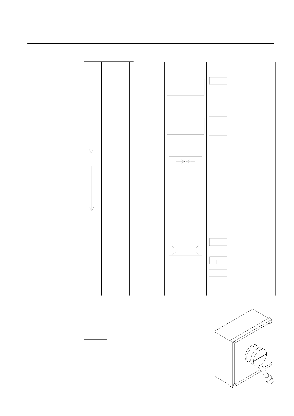
S9 Steering Lever
The S9 steering lever is intended for use together with
e.g. AP45 Autopilot. Several units ca n be connected in
parallel, but only if configured as alternative 1 (see
next page)
Operation
Activation is achieved by pulling out the lever. The
lever is spring loaded to mid position , and can be use d
for starboard or port rudder commands. After
finishing the manoeuvres the lever will be locked
when pushed back to non-operational position.
Simrad Robertson AS
Egersund - Norway
Page 26
Page 2-12 Robertson AP45 Autopilot
Operation
Alternative operation.
The S9 can be configured in four alternatives. At delivery from Robertson the S9 is
connected for alternative 1. If alternative 2, 3 or 4 is to be used, S9 has to be
modified according to the chapter “S9 Steering Lever”, page 5-26.
Note!
If a F200-40 also is connected, only alternative 1 can be used.
Alternative 1 (No resistor)
S9 Lever AP45 Mode Function AP45 Displays
IN MANUAL S9 locked NON FOLLOW UP
MANUAL
OUT MANUAL NFU steering by
moving lever to
NON FOLLOW UP
MANUAL
left or right
IN AUTO,
WORK
OUT AUTO,
WORK
S9 locked
AUTOMATIC
Course change
by moving lever AUTOMATIC
Alternative 2 (R = 1K)
S9 Lever AP45 Mode Function AP45 Displays
IN MANUAL S9 locked NON FOLLOW UP
MANUAL
OUT MANUAL NFU steering by
moving lever to
NON FOLLOW UP
MANUAL
left or right
IN AUTO,
WORK
S9 locked
AUTOMATIC
H 080
H 080
A 146
A 146
H 080
H 080
A 146
OUT AUTO,
WORK
IN AUTO,
WORK
Dodging made by
lever
S9 locked.
Return to
previous course
Simrad Robertson AS
Egersund - Norway
DODGING H 080
A 146
AUTOMATIC
Page 27
Robertson AP45 Autopilot
Operation
Alternative 3 (R = 3K)
S9 Lever AP45 Mode Function AP45 Displays
Page 2-13
IN MANUAL S9 locked NON FOLLOW UP
MANUAL
OUT MANUAL NFU steering by
moving lever to
NON FOLLOW UP
MANUAL
left or right
IN AUTO,
WORK
OUT MANUAL NFU-steering by
IN MANUAL
Remains in
manual mode
until new mode
has been selected
on control unit.
S9 locked
moving lever
S9 locked.
Return to
previous course
AUTOMATIC
NON FOLLOW UP
MANUAL
NON FOLLOW UP
MANUAL
Alternative 4 (R = 5,1K)
S9 Lever AP45 Mode Function AP45 Displays
IN MANUAL S9 locked NON FOLLOW UP
MANUAL
H 080
H 080
A 146
H 080
H 080
H 080
OUT MANUAL NFU steering by
moving lever to
left or right
IN AUTO,
S9 locked
WORK
OUT MANUAL NFU-steering by
moving lever
IN AUTO,
WORK
S9 locked.
Continues on
new set course,
same as vessel’s
heading
NON FOLLOW UP
MANUAL
AUTOMATIC
NON FOLLOW UP
MANUAL
AUTOMATIC
H 080
A 146
H 080
A 080
Simrad Robertson AS
Egersund - Norway
Page 28
Page 2-14 Robertson AP45 Autopilot
Operation
FU91 Follow up Steering Lever
Operation
The FU91 is activated by operating the push to
take command (PTTC) button. When in
“COMMAND”, the button light is switched on
and the autopilot INFO display will show:
FOLLOW UP
HELMSMAN
Rudder commands are made by setting the lever
to the required rudder angle, wherafter th e
rudder will move to the commanded angle and
stop.
FU91 may be connected to AP45 in two different
ways. See Fig. 5-32 and Fig. 5-33
FU91 without mode switching
The lever can only be activated when the autopilot is in Helmsman mode. Pressing
the PTTC button repeatedly will toggle between NFU and FU mode on AP45. See
table below.
FU91
Switch
AP45
Mode
Function AP45 Displays
OFF MANUAL NFU steering by NFU
lever or push button
control
ON MANUAL Foll ow Up steering by
moving FU91 lever to
desired rudder angle
as read on FU91
ON-OFF AUTO Automatic steering
Note!
If the Helmsman button is pressed when the FU91 is active, or if a NFU lever is
operated, the autopilot will go to NFU mode even though the PTTC button light is
on. However, as soon as the FU91 is operated again (lever is moved), the autopilot
will resume FU mode.
For safety reason, the FU91 should always be switched to OFF when not in use.
FU91 with mode switching
The lever can be activated also with autopilot in Auto mo de. Pressing the PTTC
button brings the AP45 into Helmsman mode. Wh at mode/sequence you get when
pressing the PTTC button again is depending on w hich value of the re sistor R is
installed (Ref. page 5-29)
R = 1K: Auto - Dodge - Auto (previous course)
R = 3K: Auto Manual - Manual
R = 5,1K: Auto - Manual - Auto (new course)
NON FOLLOW UP
MANUAL
FOLLOW UP
MANUAL
* * * * *
AUTO
H 085
H 085
A 080
The mode change sequence is in principle similar to S9 oper ation alt. 2, 3 and 4
explained at page 2-12 and 2-13.
Simrad Robertson AS
Egersund - Norway
Page 29

Robertson AP45 Autopilot
Operation
Multiple FU91 installation
The operation of each lever is identical to above description of a single lever.
Activating one FU91 will deactivate the one that was previously active.
FU91 and S9 connected to the same autopilot
It is recommended not to have both S9 and FU91 in operational condition at the
same time. This may create confusion and inadvertent operation . The main rules
are:
• Always put the S9 lever to locked position after use .
• Always switch the FU91 to OFF after use.
Page 2-15
Simrad Robertson AS
Egersund - Norway
Page 30

Page 2-16 Robertson AP45 Autopilot
Operation
Fault warnings
The following fault warnings may be shown on the Information Display:
OFF COURSE
RESET ALARM
Course deviation is greater than selected off course alarm limit. Press the Alarm
button to cancel the alarm. The alarm is automatically reset when the vessel is
back within the limit.
RUDDER FEEDBACK
FAIL!
Indicates that the autopilot is not r eading r udder f eedback sig nal. By pre ssing the
alarm reset button, the audible alarm will be re set and th e auto pilot will sw itch to
a simulated signal, instead of the real. This is indicated by a flashing * * SIM * *
on the information display. Repair actions should be taken when back in port.
NO RESPONSE
FROM RUDDER
If a rudder command is not executed, or the rudder moves in wrong direction, this
message will be shown on the display. The reason can be a malfunction of the
steering gear, or simply that the steering gear is not switched on.
NAVDATA NOT REC.
CHANGE MODE
Check that the nav. receiver is turned on and set up properly (see nav. receiver
manual).
POOR NAVDATA
CHANGE MODE
Poor reception conditions or improper set-up of nav. receiver.
WRONG DATAFORMAT
NAVRECEIVER
Wrong NMEA-format selected on autopilot or transmitted by nav. receiver.
MAGN.COMP.FAIL
SELECT SENS.TYPE
All three messages indicate problems with reading the signals from the navigation
receiver. If you are unable to cure the problem, the NAV-mode should not be used
before a Robertson dealer has been consulted.
These alarms will be given w hen the autopilot is u nable to detect a proper sig nal
from the selected heading sensor. The reason can be a faulty sensor or wrong
selection of sensor (See “Type of Heading Sensor”, page 6-4).
FLUXGATE FAIL
SELECT SENS.TYPE
GYROCOMPASS FAIL
SELECT SENS.TYPE
DATA FAILURE
CHECK SETTINGS
If the autopilot should lose or read erratic data stored in the memory, this alarm
will be given, and the autopilot is simultaneously set to MANUAL-mode.
Simrad Robertson AS
Egersund - Norway
Page 31

Robertson AP45 Autopilot
Operation
A selection of standard settings is then automatically entered into the memory.
The standard settings will make the autopilot steer, but not to its best
performance on all vessels. They should therefore be checked (See “Selection of
parameter settings”, page 6-2).
If you prefer not to check the settings yourselves, enter the AUTO mode and
consult your Simrad Robertson dealer when back in port.
Only if Watch alarm function is enabled. Ref. “Watch alarm”, page 5-37.
The watch alarm warning signal is rep e ated ev e ry fo ur minute s as lon g as AP45 is
in Auto, Work or Nav mode and is reset by pressing Alarm reset button.
If you want to permanently disable the watch alarm function:
Press the hidden button above the + bu tton entering D ebug mode and then press
the WEATHER button repeatedly until the information display shows
SOFTWARE/RUNTIME. Press the DECREASE (-) button repeatedly (six times)
until the display shows DATA FAILURE - CHECK SETTINGS. Press the ALARM
RESET button and the Watch Alarm function is disabled.
Page 2-17
WATCH ALARM
PRESS RES BUTTON
Note!
This procedure is considered as a “Master reset” of the AP45 and you must therefore
check all settings described under “Selection of parameter settings”, page 6-2 or
consult your Simrad Robertson dealer when back in port.
For further explanation to Fault warnings, see page 7-1
Simrad Robertson AS
Egersund - Norway
Page 32

Page 2-18 Robertson AP45 Autopilot
Operation
.
Simrad Robertson AS
Egersund - Norway
Page 33

Robertson AP45 Autopilot
Design and theory of operation
3. DESIGN AND THEORY OF OPERATION
Page 3-1
Automatic Steering
An autopilot is an apparatus that controls the rudder of a vessel in order to
maintain a selected heading.
There are different design pr inciples for such an apparatus, but th ey all basically
operate as shown in Fi g. 3-1.
This diagram shows th at the vessel's heading is supplied from the compass to a
detector circuit. The de tector will sense when the vessel is off co urse and to what
side. The detected signal is amplified and directed to either energise the port or
starboard solenoids, i.e. make the rudder move one way or the other.
COMPASS
STBD. TRIGGER
DET AMP
PORT TRIGGER
SOLENOID
RUDDER
SOLENOID
FB
GYRO
COMPASS
MAG NE T IC
COMPASS
HEADING
CPU
KEYPAD
RUDDER POSITION
Fig. 3-1
Autopilot principle diag r am
PROG RAM
I/O
INTE RFACE
COURSE
SELE CTO R
DISPLAY
FEEDBACK
UNIT
DRIVER
RUDDER
FEEDBACK
RUDDER
SOLENO ID
VALVES
Fig. 3-2
Processor controlled autopilot
Simrad Robertson AS
Egersund - Norway
Page 34

Page 3-2 Robertson AP45 Autopilot
Design and theory of operation
In order to stop the rudder movement, a feedback signal is produced from the
feedback unit. The feedback signal w ill be compared with the comp ass signal and
when there is a balance between the two, the soleno id will be de-energise d. The
rudder has now been mov ed to a po sition that makes the ve ssel turn. This turn is
picked up by the compass and causes a new unbalance between the feedback
signal and the erro r signal which energise s the oppo site solenoid . Now the rudder
will start to move back towards the previous positio n, and the f eedback sign al will
again cancel out the unbalance and de-energise the solenoid to stop the rudder.
By utilising digital technology to perfo rm the function of an auto pilot, the typical
block diagram will be slightly changed. Even so, the basic operation should be
recognised on Fig. 3-2.
As we know, a microprocessor can only do what it has been programmed to. This is
called software. The program can be either fixed or partly adjustable to adapt the
microprocessor to the individual type of vessels. In Robertson terminology this is
called "setting parameters", and it will determine the performance of the autopilot.
AP45 Control Unit
CD109 Course Detector
The AP45 Control Unit contains two electro nic boards, the Control Board and the
Illumination Board. An optional navigation interface board (N40) may be supplied.
The Control Board contains the micro-computing circuitry, and a plug-in PC-board
for the Course Display. The alarm circuit is also mounted on this board.
The Illumination board consists of the display backlighting- and the Information
display electronics .
All interconnecting plugs for heading sensors, junction unit and remote controls
are mounted on the Control Board.
The two boards are intercon nected with a ribbon cable which are soldered to the
illumination board and plugged into the control board.
All parameter settings and operation of the autopilot are made using the push
buttons on the front panel.
CD109 is a magnetic compass sensor in moulded plastic. It is moun ted to a v esse l's
magnetic compass to transfer the heading information to the control unit. The
primary windings are excited by a pulsating sig nal. Dependant of the mag netism
induced by the position of the compass card magnets (Heading), pulses of variable
amplitude will be generated in the secondary sine and cosine windings. These
pulses are filtered through the R/C network and amplified before entering the A/D
converter.
N
S
Simrad Robertson AS
Egersund - Norway
HEAD 2 (COS)
HEAD 1 (SIN)
Exitation
R1
R2
C2
2.5V (Ref.)
Fig. 3-3
Course Detector principle
A/D
CONV.
Digital HeadingC1
Page 35

Robertson AP45 Autopilot
Design and theory of operation
Page 3-3
Rudder Feedback Units
RF45X Rudder Feedback Unit
The rudder feedback unit transmits rudder angle information to the control unit
and rudder angle indicators. It is mounted close to the rudder stock and
mechanically connected to the rudder tiller arm by a transmission link.
The RF45X contains a circular PCB carrying all the electronics and a long life
potentiometer con nected to the PCB by three wir es. The unit is rep airable in that
the electronics and the potentiometer can be replaced.
The electronics have two outpu t circuits. One circuit outputs f requency of 3400Hz
as midposition reference. It varies at a rate of 20Hz/degree, increasing when the
rudder moves to port and vice versa.
The other circuit outputs a current (0.1-1.1mA), to the rudder angel indicator(s)
(RI35 and RI9).
The RF45X is supplied with a fixed 4-wire, screened cable of 2 m (6 ft.). Th is cable
is meant to be spliced in the enclosed splash-proof junction box.
The shaft of the fe edback unit is free to travel 360 degre es, but only ±70 d egrees
from midposition are used for signal control.
The transmission link mechanically co nnects th e fee dback unit to the rudd er tille r
arm. It is made of stainless steel and has standard length of 450 mm.
RF14XU Rudder Feedback Unit (optional)
Fig. 3-4
RF45X principle
The RF14XU Rudder Feedback Unit consists of a glass-reinforced fire inhibiting
polyester housing with a mounting plate of seawater resistant aluminium.
Potentiometer, limit switches and an electro nic driv e mo dule are also containe d in
the unit. The electronic drive module comprises a voltage section and a frequency
section.
The voltage section outputs a voltage to the rudder angle indicator(s) which is
proportional to the rudder angle. The voltage varies ±9V with half of the supply
voltage as reference. The voltage should read zero volts with the rudder in
midposition.
The frequency section outputs a signal to the control unit with 3400 Hz as
midposition reference. It varies at a rate of 20 Hz/degree, increasing when the
rudder moves to port and vice versa.
The shaft of the Feedback Unit is free to trave l 360 degrees, but o nly ±90 degre es
from midposition are used for signal control.
Simrad Robertson AS
Egersund - Norway
Page 36

Page 3-4 Robertson AP45 Autopilot
Design and theory of operation
RF14XU is equipped with two sets of limit switches. One set can be connected in
series with the autopilot solid state switch, the other can be incorporated in an
independent hand steering system, if required.
Junction Units
J45S Junction Unit
The J45S Junction Unit operates hydraulic power units with directional valves
(e.g. Robertson RPU 1 and 3) . It has been made for 12, 24 and 32V DC oper ation.
The unit incorporates a printed circuit board with terminal block, fuse, polarity
and over voltage protection, isolated solid state output for solenoid switching and
start relay for the Power Unit, all mounted in a splash proof aluminium cabinet.
Fig. 3-5
Basic system
The J45S solid state circuit is activated from the output transistors in AP45
Control Unit and LD1/LD2 monitors the rudder commands.
Galvanic isolation is obtained by opto ’s IC1 A an d B. Q2/Q3 switche s the so leno ids
on/off. Relay K1 has a double function: Used as “safe relay”, breaking the solenoid
supply when AP45 is switched off and starting the steering gear pump when AP45
is switched on (RPU1 and RPU3).
Simrad Robertson AS
Egersund - Norway
Page 37

Robertson AP45 Autopilot
Design and theory of operation
Page 3-5
Fig. 3-6
Solenoids with po sitive common
Fig. 3-7
Solenoids with negative common
Simrad Robertson AS
Egersund - Norway
Page 38

Page 3-6 Robertson AP45 Autopilot
Design and theory of operation
J45A Electronic Junction Unit
The J45A operates reversible hydraulic power units with variable speed control
(RPU80, RPU160, RPU200 and HLD2000) and reversible electro mechanical
power units (MRD100). The u nit consists of a printe d circuit board w ith terminal
block, fuse, motor drive electronics and reversing relay mounted in the same type
of aluminium cabinet as the J45S.
Rudder commands from AP45 Control Unit to IC3 A and B makes the relay RL1
change the po larity to the mo tor. IC2A en sures the mo tor brake is switche d on by
T2 when there is no rudder commands from AP45. IC2A also controls a “dead
time” (delay) to ensure the RL1 relay contacts have physically changed position
before voltage is applied to the motor. This prevents arcing of relay contacts.
Adjusting RV1, preset speed, the output pulse width is decreased/increased, hence
the voltage (RMS) to the motor is changed, adjustable 0-12V.
Connecting straps S1 and S2 provides adjustable 0-24V output for 24V drive units.
Connecting an external strap from terminal 2 to 4 will enable a “Soft start”
function, which reduces the start current and is recommended for the most
powerful drive units like RPU200, RPU300, HLD2000LD and MRD100.
Fig. 3-8
J45A principle
Simrad Robertson AS
Egersund - Norway
Page 39

Robertson AP45 Autopilot
Technical specifications
AP45 Control Unit
Dimensions:................................................See Fig. 4-1
Weight:........................................................3.0 kg
Protection:...................................................IP43*
Ambient temperature, storage: ............–25 - +70°C
Safe distance to magnetic comp.: ..............0.3m
Maximum current consumption :..............0.6A
Input signals:
Rudder Feedback: ......................................3400 Hz, 20 Hz/deg.
Magnetic, Fluxgate and Gyro compass: sin/cos ±2V, 2.5V ref.
Nav.signal : NMEA 0183/180 (APA, APB, XTE, XTR,
* The IP code is an intern ational code that deals with prote ction ag ainst intrusion
of particles and water. IP43 mean s that the unit is protected against solid obj ects
greater than 1.0 mm and against spraying water from above up to 60° from
vertical. Best protection is obtained with the front mounted horizontally.
Page 4-1
4. TECHNICAL SPECIFICATIONS
operation: ........0 - +55°C
RMB, BWW, BWC, BWR, BOD, HSC).
Fig. 4-1
AP45 Control Unit - dimensions
Simrad Robertson AS
Egersund - Norway
Page 40

Page 4-2 Robertson AP45 Autopilot
Technical specifications
CD109 Course Detector
Dimensions:................................................See Fig. 4-2
Protection:...................................................IP56
Ambient temperature, storage: ............–40 - +85°C
operation: ........–30 - +60°C
Cable length:...............................................1 m
1000 (39.4")
)
"
4
.
120°
2
(
0
6
Ø
)
"
3
.
1
(
3
3
Ø
35 (1.4")
Fig. 4-2
CD109 Course detector
120°
120°
m in/m a x. 80 -10 0 (3 .2-4 .3")
Simrad Robertson AS
Egersund - Norway
Page 41

Robertson AP45 Autopilot
Technical specifications
Page 4-3
RFC35NS Fluxgate compass
Dimensions.............See Fig. 4-3
Heading output:.....Serial and analogue
Output format: .......NMEA183 10x/sec. and sine/cosine.
NMEA data:............$IIHDM,x.x,m*hh<cr><If>
x.x=heading, hh = checksum
Analogue data:........Sine/Cosine ±2V, 2.5VDC reference.
Accuracy: ................<1.25° rms
Repeatability: .........<0.2° rms
Calibration: ............Automatic
Roll & Pitch: ..........±35°
Supply:....................10-29 VDC, 1 W
Temperature:
Operation: .......0 to +55°C (+32 to + 130°F)
Storage: ...........–30 to +80°C (–22 to +176°F)
Protection:...............IP56
Mounting.................Deck or bulkhead
Cable supplied:.......0.3m (1 ft.) with Viking connector for Robertson autopilots
(Sine/Cosine data) and N2500 NMEA Interface.
Fig. 4-3
RFC35NS - Dimensions
Simrad Robertson AS
Egersund - Norway
Page 42

Page 4-4 Robertson AP45 Autopilot
Technical specifications
G40A Gyro Interface
Dimensions:................................................See Fig. 4-4
Signals in....................................................- 6 step/degree with positive or
negative common
- Synchro signal, 90:1 or 360:1, gyro
excitated
- SKR80/82 current loop (9600 Baud)
Signal level in:............................................- Stepper signal: 20 - 70V DC
- Synchro signal: 40 - 115V, 50 - 400Hz
Load:............................................................Maximum 20mA
Supply voltage:...........................................12V DC (autopilot supplied)
Power Consumption:..................................2.4 W
Ambient temperature, storage: ............–25 - +70°C
operation: ........ 0 - +55°C
G45 Gyro Interface
Fig. 4-4
G40A Gyro Interface - dimensions
Dimensions:................................................See Fig. 4-8
Signals in - Synchro signal, 1:1
Signal level in (S1, S2, S3):........................- High voltage, 80V L-L
- Low voltage, 11,6V L-L
Signal out (Synchro excitation):................26V 400 Hz, max 5 VA
Supply voltage:...........................................12V DC (autopilot supplied)
Ambient temperature, storage: ............–25 - +70°C
operation: ........ 0 - +55°C
Simrad Robertson AS
Egersund - Norway
Page 43

Robertson AP45 Autopilot
Technical specifications
Page 4-5
FI100-40 Fluxgate Interface
Dimensions:................................................See Fig. 4-5.
Cable length:..............................................2 m (with plug)
Ambient temperature, storage:............–25 - +70°C
operation: .......–10 - +55°C
Input signal: ...............................................sine/cosine
Output signal:.............................................sine/cosine ±2V DC at +2.5V reference
160 (6.3")
144 (5.67")
34 ( 1 .3 4")
148 (5.83")
25 (0.9 8 " )
3.5 (0.14")
47 (1.85")
89 (3.5 ")
Fig. 4-5
FI100-40 Fluxgate Interface - dimensions
RF45X Rudder Feedback Unit
Dimensions:................................................See Fig. 4-6.
Protection:...................................................IP56
Ambient temperature: ...............................–10 - +55°C
Operating voltage:......................................12V DC (autopilot supplied)
Frequency output, Feedback: ....................3400Hz (midship reference)
Port: +20Hz/degree, stbd: -20Hz/degree
Current output, Indicator..........................0.1mA - 1.1mA
Capacity:.....................................................5 indicators in series
Rudder angle: .............................................±45°
Cable length:...............................................2 m (6 ft)
Fig. 4-6
RF45X Rudder Feedback - dimensions
Simrad Robertson AS
Egersund - Norway
Page 44

Page 4-6 Robertson AP45 Autopilot
120 (4.8")
40 (1.6")
75 (3")
80 (3.15")
Ø12 (0.47")
185 (7.3")
150 (5.9")
240 (9.5")
160 (6.3")
Ø
8
(
0
.
3
"
)
Technical specifications
RF14XU Rudder Feedback Unit
Dimensions:................................................See Fig. 4-7.
Protection:...................................................IP56
Ambient temperature: ...............................–10 - +55°C
Operating voltage:......................................19-40V
(Frequency section 12-40V DC)
Voltage output, Rudder indicator:.............0-18V DC (9V as midship reference)
Frequency output, Autopilot feedback:.....3400Hz (midship reference)
Port: +20Hz/degree, stbd: -20Hz/degree
Rudder indicator capacity:.........................5 indicators in parallel
Rudder angle: .............................................+/-45° (Changeable to 60, 70 or 90°)
Limit switches: ...........................................Adjustable from ±5 to ±160°
Fig. 4-7
RF14XU Rudder Feedback unit - dimensions
Simrad Robertson AS
Egersund - Norway
Page 45

Robertson AP45 Autopilot
Technical specifications
Page 4-7
J45S Junction Unit
J45A Junction Unit
Dimensions:................................................See Fig. 4-8.
Protection: ..................................................IP22
Ambient temperature, storage:............–25 - +70°C
operation: ........0 - +55° C
Safe distance to magnetic compass:..........1.5 m
Supply voltage:...........................................12, 24, 32V DC ±20%
Max. solenoid load:.....................................3A
Dimensions:................................................See Fig. 4-8.
Protection:...................................................IP22
Ambient temperature, storage: ............–25 - +70°C
operation: ........0 - +55° C
Safe distance to magnetic compass:..........1.5 m
Max. motor load:.........................................10A continuous
20A peak
Supply voltage:...........................................12, 24, 32V* DC ±20%
*) For 32V DC the J101A/32V Adapter must be used.
Fig. 4-8
J45S/J45A/G45 - Dimensions
Simrad Robertson AS
Egersund - Norway
Page 46
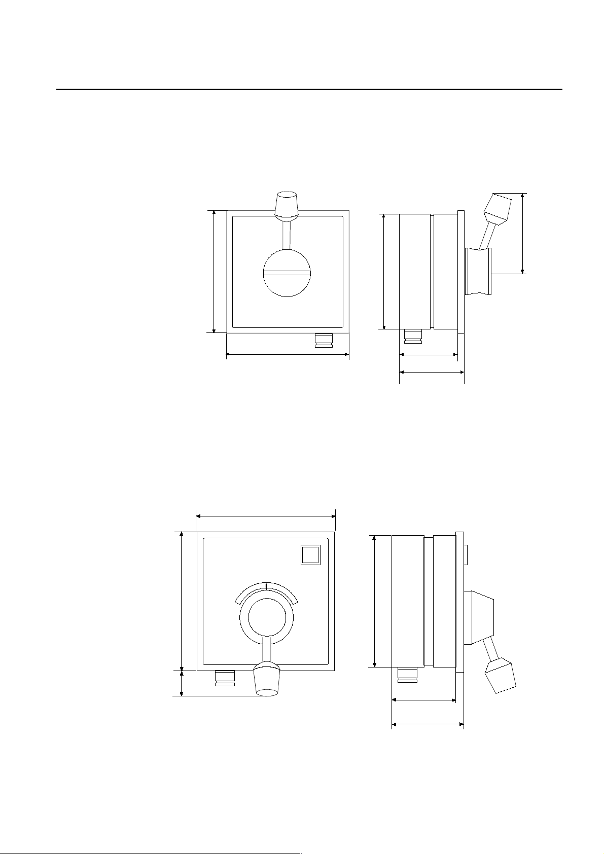
Page 4-8 Robertson AP45 Autopilot
Technical specifications
S9 Steering Lever
Dimensions:................................................See Fig. 4-9.
Protection: ..................................................IP56
Ambient temperature:...............................–25 - +70°C
Safe distance to magnetic compass:..........0.3 m
Max. inductive load:...................................4A/24V DC, 60mA/110W AC,
25mA/220V AC
144 (5.67")
144 (5.67")
Panel cut-out:138x138 (5.44")
137 (5.40")
70 (2.75")
78 (3.1")
Fig. 4-9
S9 Steering Lever - Dim ensions
95 (3.75")
FU91 Steering Lever
Dimensions:................................................See Fig. 4-10.
Protection:...................................................IP56
Ambient temperature, storage: ............–25 - +70°C
operation: ........–10 - +55°C
Safe distance to magnetic compass:..........0.3 m
144 (5.67")
144 (5.67")
30 (1 .1 8" )
Panel cut-out:138x138 (5.44")
137 (5.40")
68 (2.68")
76 (3.00")
Fig. 4-10
FU91 Steering Lever - Dimensions
Simrad Robertson AS
Egersund - Norway
Page 47

Robertson AP45 Autopilot
Technical specifications
Page 4-9
S35 Steering Lever
Dimensions:..............................See Fig. 4-11.
Weight: ....................................1.4 kg (inclusive cable)
Max. inductive load:.................4A/24V DC, 60mA/110V AC, 25mA/220V AC
Temperature range: .................Storage: –30 to 80° C
Operation: –10 to 55° C.
Environmental protection:.......IP56
Safe distance to compass: ........0.5 m (1,6 ft.)
Power consumption (light):......6 mA
Cable: ........................................10 m cable with six wires connected through
bottom gland
Note! Cable gland can be moved to the back side.
Fig. 4-11
S35 Steering Lever - Dimensions
Simrad Robertson AS
Egersund - Norway
Page 48

Page 4-10 Robertson AP45 Autopilot
Technical specifications
F1/2 Remote Control
Dimensions:................................................See Fig. 4-12
Protection:...................................................IP56
Cable length:...............................................10 meters (30 ft.)
Max. inductive load:...................................4A/24V DC, 60mA/110W AC,
25mA/220V AC
76 (3.0")
210 (8.3")
65 (2.6")
F200-40 Remote Control
Fig. 4-12
F1/2 Remote Control - Dimensions
Dimensions:........................ See Fig. 4-13.
Protection:........................... IP56
Ambient temperature,
storage:........................... –25 - +70°C
operation:....................... 0 - +55° C
Safe distance to
magnetic compass: ............. 0.3 m
Cable length:....................... 7 m (21ft.)
72 (2.8")
5 (0.2")
46 (1.8")
30 (1.2")
145 (5.7")
Simrad Robertson AS
Egersund - Norway
Fig. 4-13
F200-40 Remote Control
Dimensions
Page 49

Robertson AP45 Autopilot
Technical specifications
Page 4-11
RI35 Rudder Angle Indicator
Dimensions:..............................See Fig. 4-14.
Weight: .....................................1.0 kg
Supply voltage:.........................12/24V DC –25%/+30%, polarity independent
Power consumption:.................Max 3 W
Input signal: .............................Frequency 3400 Hz (midship reference),
±20Hz/degree
Current: 0.1 - 1.1mA (midship 0,6mA),
polarity independent
Accuracy:...................................±3° (Indicator alone)
Temperature range: .................Storage: –30°C to +80°C
Operating: –10°C to +55°C
Environmental protection:.......IP56
Safe distance to
magnetic compass: ...................0.3 m (1 ft)
Cable: ........................................20 m, single twisted pair (not connected).
Rudder Feedback Units: ..........RF300 (frequency signal),
RF45X (current signal)
Fig. 4-14
RI35 Rudder Angle Indicator - Dimensions
Simrad Robertson AS
Egersund - Norway
Page 50

Page 4-12 Robertson AP45 Autopilot
Technical specifications
RI9 Rudder Angle Indicator
Dimensions:................................................See Fig. 4-15.
Supply voltage:...........................................24/32V DC ±20%
Current consumption:................................Maximum 100 mA
Input signal:................................................. Voltage (0-18V) or
current (0.1 - 1.1mA)
Rudder angle: .............................................45°-0-45° (other angles as option)
Ambient temperature, storage: ............–25 - +70°C
operation: ........–10 - +55°C
Protection:...................................................IP56
Safe distance to magnetic compass:..........2.6 m (9 ft.)
Rudder Feedback Units: RF45X, RF14XU, RF14XI.
144 (5.67")
RI9
144 (5.67")
153 (6.02")
137 (5.40")
Panel cut-out:138x138 (5.44")
RI9 Rudder Angle Indicator - Dimensions
57 (2.24")
65 (2.56")
Fig. 4-15
Simrad Robertson AS
Egersund - Norway
Page 51

Robertson AP45 Autopilot
Installation
Page 5-1
5. INSTALLATION
Unpacking and handling
General
AP45 Control Unit
Care should be taken when unpacking and handling the equipment. A visual
inspection should be made to check that the equipment has not been damaged
during shipment and that all components and parts are present according to the
packing list.
Common sense should be used when installing the units, particular attention
being given to the operator's need for ease of access.
For cable layout refer to the External Cabling Diagram, Fig. 5-4.
For connection of several units to the J3 connector, refer to Fig. 5-36.
The unit is built to standard DIN dimensions for console mounting. Dimensions
for the panel cut out are shown on Fig. 4-1. A fastening device for console
mounting and a bracket for panel mo unting are su pplied with the equipm ent. The
mounting bracket has four screw holes for bulkhead mounting, and the Control
Unit is fitted to the bracket by two Allan screws (Fig. 5-2). A matching Allan
wrench is supplied.
It is important to locate the Control Unit so that
the viewing angle to the displays are between 45
and 90 degrees in both planes. When console
mounting, locate the control unit as near the
front edge as possible. This makes the reading
of the displays easier. Avoid direct sunlight on
the display.
Fig. 5-1
AP45 Control Unit - Panel mount
Fig. 5-2
AP45 Control Unit - Bracket mounting
Simrad Robertson AS
Egersund - Norway
Page 52

Page 5-2 Robertson AP45 Autopilot
Installation
Connector assemble
The cable conductors are connected to the connector block according to separate
connection diagrams. The following tools are required to crimp the connector pins
and sockets to the individual cable conductors.
Crimping tool :
Amp 90277-1
Extraction tool:
Amp 725840
Note!
Do not use other tools
than those specified!
For protection against electro magnetic interference, all cont rol unit connectors
must be fitted with the supplied metal shell and cover.
Strip about 1 cm (0.4") of the cable in sulation and pull the screen backwards to
cover the insulation. Screw the connector block onto the actual control unit socket.
Screw the shell onto the connector block. Fix the cable screen to the shell by a wire
strap and tighten well to make sure the screen has good contact. Apply a thin
layer of pure Vaseline on the shell threads. Screw the cover onto the shell until it
makes good contact with the control unit cabinet.
The control unit has a ground terminal and must have a proper ground connection
to the hull. The gro unding wire should be as sho rt as possible and at least 10 mm
wide.
Fig. 5-3
Control unit - connector mounting
Simrad Robertson AS
Egersund - Norway
Page 53

Robertson AP45 Autopilot
Installation
Page 5-3
Fig. 5-4
AP45 External cabling diagram
Simrad Robertson AS
Egersund - Norway
Page 54

Page 5-4 Robertson AP45 Autopilot
Installation
Heading sensors
General
Magnetic compass
AP45 is designed for connection to one compass only. However, a combination of
two compasses are possible as CD109 and Fluxgate/Gyro h as separate input pin s
in the J2 Compass connector. This means you can combine a magnetic compass
with either a fluxgate- or a gyrocompa ss.
The type of heading sensor used in the standard scope of supply may vary from
distributor to distributor as a result of practical experience and the preferences of
their market place.
The CD109 Course Dete ctor is fitted to the vesse l's existing magnetic compass or
to one particularly installed for the autopilot (“Magnetic compass”, page 5-4.).
The Robertson RFC35NS Fluxgate Compass can be connected directly to the
control unit (“RFC35NS Fluxgate Compass”, page 5-6), whilst other makes of
fluxgate compasses require a FI100-40 Fluxgate Interface (“FI100-40 Fluxgate
Interface”, page 5-8).
If a gyrocompass is used as heading sensor, the G40A or G45 Gyro Interface is
required (page 5-9).
To obtain an accurate heading from the magnetic compass, great care should be
taken when determining the location of the compass.
Select a location that provides a solid horizontal mounting base, free from
vibration and as close to the vessel's centre of ro ll and pitch as possible . It should
be as far as possible from disturbing magnetic interference such as the engines,
cables, transmi tter antennas or other electro magnetic objects.
Note! The compass must be compensated.
Heeling error
Heeling error may be observ ed when the boat is rolling and pitching, causing an
unstable compass card. This can be adjusted for by using a "heeling magnet"
placed vertically below or above the exact centre of the compass. The magnet is
normally placed with the red end up in the Northern hemisphere and the blue end
up in the Southern hemisphere. The correct distance between magnet and
compass can best be found during sea trials. The heeling error can also be reduced
by mounting the compass close to the vessel's centre of roll and pitch.
Northerly/southerly turning error
Symptoms of northerly turning error are that the vessel is "S-ing" on northerly
headings when at high latitudes. The reason for this phenomena is that the earth's
magnetic fluxlines are parallel to the earth's surface only at the equator, and thus
no vertical magnetic component exists. When moving further north from the
equator, the vertical component of the earth's magnetic field increases.
The directional reading from a magnetic compass is based upon the horizontal
component of the earth's magnetic field. This component becomes smaller and
smaller with increasing latitude, while the v ertical magne tic compon ent incre ases.
The resulting ef fect at high latitud es is that magnetic c ompasses beco me sluggish
and appear to be unstable. These symptoms become more apparent as speed
increases.
The same phenomena is experienced in the southern hemisphere, but on southerly
headings and is referred to as southerly turning error.
There is no patent cure for this problem, besides making a proper installation and
compensation of the compass.
CD109 Course Detector mounting
Simrad Robertson AS
Egersund - Norway
Page 55

Robertson AP45 Autopilot
Installation
The course detector is
mounted on the ship's
magnetic compass to
transmit a heading
signal to the control
unit. The mounting
method will depend
upon the compass
design. The distance
between the course
detector and the
compass card depends
upon the magnetic
momentum of the
compass card
magnets. A distance
of 70-90 mm for a
magnetic moment of
1500-2000 cgs is
therefore
recommended. For
adjustment of signal
level, see “Course
Detector Alignment”
page 6-2. If a nonRobertson supplied
magnetic compass is
used, it is advisable to consult a qualified compass adjuster for mounting of the
CD109.
Page 5-5
Fig. 5-5
CD109 Course detector - Mounting
For mounting instructions refer to Fig. 5-5. The course detector can be attached to
the compass either by a 6 mm screw to the bottom of the compass bowl or by use of
the tri-pod holder supplied with t he course detector.
The course detector is also supplied with cable (1m) feed and plug. Socket and
connector with bracket for extension cable are in the standard scope of supply. The
extension cable is optional equipment.
The compass should be checked for free movement in the gimbals without
stressing the detector cable.
The CD109 Course Detector is connected to J2 on the Control Unit, and the
connection is shown on the Wiring Diagram (Fig. 5-23).
If the Course Detector is mounted up-side down on top of the compass, the
sine/cosine signal on J2 pin 10 and 11 must be interchanged.
Simrad Robertson AS
Egersund - Norway
Page 56

Page 5-6 Robertson AP45 Autopilot
Installation
RFC35NS Fluxgate Compass
Mounting
The RFC35NS (part no. 22083596) substitutes the Robertson RFC250 Fluxgate
compass. It comes with a “pigtail” c able that matches the Viking connecto r on the
RFC250 (extension) Cable part no. 20183554. The internal connection of the
“pigtail” cable is shown on Fig. 5-7. Heading output is on sine/cosine and
NMEA0183 formats.
Note!
On new installations together with AP45 you need the standard RFC250 Cable
part no. 20183554. Cut off the Viking connector at one end and replace it with the
AP45 AMP type connector (J2) as per Fig. 5-6.
An extra cable gland is supplied for a separate NMEA cable co nne ctio n if requ ired .
Disconnect the brown and blue wires to J1-2 and J1-1 and connect the separate
cable instead. See Fig. 5-7.
The RFC35NS contains a magnetic fluxgate sensor and great care shou ld be take n
when deciding the mounting location.
To minimize the effect of heeling errors, installation on the fly bridge or in the
mast is not recommended.
Select a location that provides a solid
mounting place free from vibration and as
close to the vessel's centre of roll and pitch as
possible, i.e. close to the water line. It should
be as far as
possible from
disturbing
FWD
magnetic
influences such
as engines (min.
2 meters),
ignition cables,
other large metal
objects and
particularly the
autopilot drive
unit.
The RFC35NS compass must be mounted with the cable glan d pointing aft.
Note!
The compass should be deck mounted to allow for mechanical alignment. The
compass face plate on the RFC35NS is the TOP. Never mount it upside down! Level
the sensor as close to horizontal as possible.
Use the supplied mounting kit and drill holes through the centre of the slots.
Simrad Robertson AS
Egersund - Norway
Page 57

Robertson AP45 Autopilot
Installation
Connection
Page 5-7
Fig. 5-6 AP45/RFC35NS - connection
Calibration
SIN PCB
J1
NMEA
654321
VIN-
RX-
RX+
WHITE (VIN+)
BROWN (TX-)
RFC35NS
NMEA/RA TE PC B
BLUE (TX+)
K
C
E
A
L
R
B
G
J2
ROBNET
4
D
E
R
+
W
T
N
O
E
E
L
L
L
O
E
I
Y
V
J3
EXT.COMP
11223
0,5 m
Cable 22083661
Fig. 5-7 RFC35NS - Internal connection
The calibration is carried out by using the “RFC250 procedure”:
1. Switch on the autopilot to supply power to
RFC35NS.
2. Make two 360 degree turns to starboard within 5
minutes after switch on. Make sure the boat passes
3 times through North (see figure). Ensure smooth
and slow movements. A minimum of roll and
acceleration will give the best result. As soon as
north is passed for the 3rd time, there will be a
confirmation in the autopilot display (see below).
Original RFC250 cable
(Part no. 20183554)
• Provided you have an AP45 with software version V1R3 or V1R4 (latest),
you will read "Fluxgate compass compensated" in th e info display wh en the
calibration is completed. Press the alarm button to reset. There w ill be no
Simrad Robertson AS
Egersund - Norway
Page 58

Page 5-8 Robertson AP45 Autopilot
Installation
confirmation in the display if the AP45 has a sof tware revision earlier than
V1R3.
Alignment
FI100-40 Fluxgate Interface
Carry out the calibration procedure, then steer the boat on a known heading or
bearing. Slightly turn the heading sensor until the correct heading readout is
displayed. Tighten the screws.
Note!
If you sail the boat more than 15-20° north or south of the latitude of your last
calibration, the calibration procedure should be repeated. Calibration data is
stored in the RFC35NS and will only be deleted when a new calibration is
performed.
When connecting fluxgate compasses other than Robertson types, the FI100-40
Fluxgate Interface must be connected between the compass and the control unit.
The interface unit is bulkhead (or table) mounted with two screws.
The fluxgate compass is con nected to a terminal board in the FI100-40 accord ing
to the diagram enclosed w ith the unit. FI100-40 is connected to J2 of the control
unit according to Fig. 5-8.
Fig. 5-8
AP45/FI100-40 Fluxgate Interface - Wiring
Simrad Robertson AS
Egersund - Norway
Page 59

Robertson AP45 Autopilot
Installation
Page 5-9
G40A Gyro Interface Unit
The G40A is required when a Gyro Compass with geared synchro or stepper
signal output is connected to AP45. The unit shall be mounted not more than two
meters from the AP45 control unit. This is to avoid voltage drop and reduce
interference via the interconnecting cables.
All cable conductors are terminated in screw terminals on the G40A PCB. For
cabling and connections see Fig. 5-9. For screen termination, see Fig. 5-22.
Fig. 5-9
G40A Gyro Interface Connections
There are also three plug-in straps on the PCB, one for each phase. The position of
the straps makes the G40A to operate from either positive or negative stepsignals. For setting of the straps, refer to Fig. 5-10. The shown strap position
enables step signals with positive common. For negative common, insert strap
vertically, A1-A3, A2-A4 and so on.
In addition a DIP switch is included. Switch no. 1 sets gear ratio:
360:1 = switch to 0 (OFF)
90:1 = switch to 1 (ON)
The remaining switches 2, 3 and 4 are for test purpose on ly and shall be 0 (OFF)
for normal use. Refer to table on page 7-3.
For SKR80/82 current loop, switch no. 2 shall be set to ON, the others to OFF.
Fig. 5-10 shows the location of the switches and LED's.
The potentiometer VR1 is factory set to 2.5V reference voltage, and should not be
readjusted.
Simrad Robertson AS
Egersund - Norway
Page 60

Page 5-10 Robertson AP45 Autopilot
Installation
Fig. 5-10
G40A PC-board - Switch location
Power turn-on
After power turn-on, verify that the LED D8 is lit. This indicates that the
regulated 5V is OK.
If step-signals are connected, the LED’s D1, D2 and D3 should not be lit. If they
are, pull out the plug-in straps and insert them in the vertical direction. The LEDs
D5, D6 and D7 shall turn on and off in a Gray- code sequence when changing the
gyro heading.
If synchro signals are connected, the position of the plug-in straps is irrelevant.
However, if the read-out from the AP45 does not follow the gyro, phase S1 and S3
may have to be interchanged.
The LED D4 shows the presence of the synchro reference voltage, and the LEDs
D1, D2 and D3 will turn on with variable intensity, depending on the phase
voltage.
If the heading read -out has an off set, this is compensate d by the “Gyro Adjust” in
the “Installation loop”. See “Type of Hea d ing Sensor”, page 6-4, for details.
Select “Gyrocompass” - “Geared/Stepper” in the AP45 Installation loop.
Simrad Robertson AS
Egersund - Norway
Page 61

Robertson AP45 Autopilot
Installation
Page 5-11
G45 Gyro Interface Unit
The G45 is required when a gyrocompass with 1:1 ratio synchro signal is
connected to AP45.
There is separate terminals for high voltage (80V L-L) and low voltag e (11,6V L- L)
synchro input. Input terminals not used should be short circuited as shown in
connection diagrams.
G45 can also be used for excita tion of a “dead” synchro trans mitter.
The unit shall be moun ted w ithin th e cable le ngth (3 m) from the auto pilot con trol
unit. In case the cable has to be extended, the 2.5V reference voltage must be
checked and eventually readjusted in accordance with “TROUBLE SHOOTING”,
page 7-8 to maintain the accuracy.
All cable conductors are terminated in screw terminals on the G45 PCB. For
cabling and connections see Fig. 5-11.
The PCB contains four trim potentiometers which are all facto ry set and should
normally need no readjustment.
Select “Gyrocompass” - “1:1 Synchro” in the AP45 Installation loop. See
“Installation loop”.
Fig. 5-11
Connection to G4 5 excitated synchr o transmitter
Fig. 5-12
Connection to gyro excitated synchro transmitters
Simrad Robertson AS
Egersund - Norway
Page 62

Page 5-12 Robertson AP45 Autopilot
Installation
RGC Signal Interface Unit
Fig. 5-13
G45 Input/output
(Part of RGC Gyrocompass delivery)
The RGC Signal Interface Unit is designed to generate heading signals of different
formats when connecte d to either RGC50, RGC10 or RGC11. The heading signal
used by AP45 is the sine/cosine output, and the interconnection is shown in Fig.
5-14.
The unit comprises one PCB mounted in a J45A/J45S type box.
Further details, such as installation, technical specifications and eventual
adjustments are described in the “RGC Interface” addendum in the RGC
Gyrocompass manual.
Fig. 5-14
AP45/RGC Signal Interface Unit - Wiring
Note!
Select “1:1 SYNCHRO” via the “INSTALLATION LOOP”.
Simrad Robertson AS
Egersund - Norway
Page 63

Robertson AP45 Autopilot
g
Installation
Page 5-13
RF45X Rudder Feedback Unit
The RF45X is normally mounted with the
shaft pointing upwards. It can, however,
also be mounted with the shaft pointing
downwards if that appears to be more
convenient.
NOTE!
In case of an “upside-down” installation,
the two plug-in straps on the component
°
side of the PCB have to be “turned” 90
to
achieve reversed output signal. (To remove
the PCB from the housing, simply grip the
potentiometer and pull.
Shaft pointing up: Strap S2 to “N(ormal)”
Shaft pointing down: Strap S2 to
“I(nverted)”.
It should be noted that an “upside-down”
installation will make any adjustment and
service more convenient as the unit then
can be opened without removing the unit
from the mounting base.
Fig. 5-15
RF45X Internal Wirin
Fig. 5-16
RF45X Rudder Feedback Unit - Mounting
Use the attached template (Fig. 5-18) to drill the required mounting holes. The unit
is fastened to the mounti ng b as e by t he t wo All en s crews encl os ed. (Ot her t ypes of
screws may be used if fast ened t o i.e. a wooden b as e. )
Make the parallelogram configuration of the transmission link (see Fig. 5-16) and
fasten the link to the RF45X shaft preliminary. The transmission link can be
shortened by cutting of a piece of the rod (us i ng a ha cks aw). Move t he rudder
Simrad Robertson AS
Egersund - Norway
Page 64

Page 5-14 Robertson AP45 Autopilot
Installation
manually h.o. - h.o. and make s ure t he tr ans mi ss i on lin k i s movi ng freely i n bot h
directions.
Electrical connection
The cable should be connected to the junction unit according to Fig. 5-23 - Fig.
5-26. When splicing cable in the junction box, use the enclosed crimp pins on each
wire of the extension cable. Otherwise the wires may be cut off at the terminal
point when tightening the screw.
The screen is open in RF45X a nd sh ould be connect ed in the junct ion uni t.
For final alignment, see page 6-1.
RF14XU Rudder Feedback Unit
Mechanical mounting
Before installation check that the alignment mark on the mounting plate agrees
with the mark on the shaft. Bring the rudder to Amidships position. The feedback
unit should be mounted on a plane surface and se cured by bo lts through th e three
holes in the mounting p late. It should be linked to the rudder in accordance with
Fig. 5-17. It is important that the linkage is linear, i.e. the A-a and D-d are pairs of
equal length. This will give a ratio 1:1 between the ru dder angle and that of the
feedback unit shaft.
Note!
If the RF14XU is mounted with the shaft pointing upwards, the yellow and the blue
lead to the potentiometer inside must be interchanged (See Fig. 5-20).
Fig. 5-17
RF14XU - Mounting
Simrad Robertson AS
Egersund - Norway
Page 65

Robertson AP45 Autopilot
Installation
Page 5-15
Fig. 5-18
RF45 Template
Scale 1:1
Simrad Robertson AS
Egersund - Norway
Page 66

Page 5-16 Robertson AP45 Autopilot
Installation
Simrad Robertson AS
Egersund - Norway
Page 67

Robertson AP45 Autopilot
Installation
Electrical installation
Electrical connection is shown in Fig. 5-21. The cables are carried through cable
glands and connected to the terminal board. If required, to avoid an y mechanical
damage, the cables should be run in a conduit between the rudder feedback unit
and the junction unit or rudder indicator. The cable screen must be connected to
the internal ground terminal. Ref. picture below.
The feedback unit has an external ground terminal and must have a proper
ground connection to the hull. The grounding wire should be as short as possible
and at least 10 mm wide.
The RF14XU can be powered either from the rudder angle indicator supply (1940V DC) or directly from the autopilot j unction un it. If a rudder angle indicato r is
connected, the RF14XU is powered from the rudder angle indicator supply. If the
rudder angle indicator voltage disappears, or rudder angle indicator is not
connected to the RF14XU, the feedback unit is powered directly from the
autopilot. The change over is done automatically.
If RF14XU is connected to rudder angle indicators, and the indicators are powered
from an unfiltered 24V supply, the enclosed 470uF capacitor should be connected
across the supply. Without the capacitor, a deviation may occur between the
autopilot feedback midposition reference and that of the rudder angle indicator(s).
Page 5-17
Note!
Fig. 5-19
Screen termination
Scaling of rudder angle
The RF14XU is normally delivered for ±45 degrees rudder angle (violet, brown and
pink leads are not connecte d). Fo r ±60 deg ree s, connect bro wn le ad to termin al 10,
for ±70 degrees, connect pink to terminal 10 and for ±90 degrees, connect the violet
lead to terminal 10. White lead must remain connected. To invert the indicator
deflection, the brow n lead to terminal 8 of the RF14XU terminal board must be
connected to terminal 9. See Fig. 5-20.
Simrad Robertson AS
Egersund - Norway
Page 68

Page 5-18 Robertson AP45 Autopilot
Installation
NOTE 2
NOTE 1
VIOLET
BROWN
PINK
BROWN
8
9
NOTE 1: Brown lead normally connected to .
Move to to in ve r t th e r u d d e r indicator deflection.
NOTE 2: Normally connected for +/-45˚ rudder angle (violet, brown and pink leads are
not connected). For +/-60˚ connect brown lead to terminal 10, for +/-70˚ connect
pink lead to terminal 10, for +/-90˚ connect violet lead to terminal 10.
Wh ite l ead mu st remai n con nec ted.
BLACK
981076
9
RF14XU ELECTRONIC MODULE
(VIEWED FROM BACK SIDE)
WHITE
RED
BLACK
WHITE
RED
5
8
BLUE (GND)
YELLOW (+5V)
GREEN ( WIPE R)
TO
POT.
METER
Fig. 5-20
RF14XU Internal wiring
Final check
After installation, the cable glan ds must be sealed with silicon to preve nt water
from seeping in . Also apply silicon grease to the gasket be tween the bottom and
top cover.
Simrad Robertson AS
Egersund - Norway
Page 69

Robertson AP45 Autopilot
Installation
On the inside of the feedback unit cover, a piece of moisture protecting sponge is
attached. The sponge produces a corrosion preventive gas, and to increase the
efficiency of the gas the cover must be kept tight.
Page 5-19
J45S Junction Unit
Fig. 5-21
RF14XU/J45S - Wiring
The junction unit is made for bulkhead mounting and secured by screws. To
minimise length of power cables (thus avoiding voltage drop), it should be
centrally located between mains panel and power unit.
Simrad Robertson AS
Egersund - Norway
Page 70

Page 5-20 Robertson AP45 Autopilot
Installation
The unit has separate mains supply for the autopilot electronics and the power
unit (motor/solenoids). This reduces the interference to the autopilot electronics
caused by the motor switching. The power unit supply cable (mains supply) should
be of at least 4 mm
2
(AWG10). The electronic supply cable should be 1,5 mm
(AWG14).
Cables from control unit, rudder feedback unit, power unit and mains supply
should be connected to the terminal blocks according to wiring diagram fig. 5.23.
Sufficient free cable should be left inside the junction unit so that the P.C. board
can be removed for repair without having to disconnect the cables from the
terminal board.
Note!
The J45S Junction Unit has been set for 24V DC operation and prewired from
factory to drive Robertson power units with solenoid valves such as RPU3 (solenoid
supply is via J45S).
If the autopilot shall operate on 12 or 32V DC, set voltage selector (plug-in strap)
to appropriate position.
Check that the FB selector is in correct position (S2-S3) for frequency feedback
signal.
2
Run two voltage feed cables as follows:
Mains input for pump motor an d soleno id valves is connected to + and - terminals
marked "Supply" (Cable dimensions 4.0 mm
2
- AWG10).
Autopilot (electronic) supply is connected to + and - terminals marked "Electronic"
(Cable dimensions 1.5 mm
2
- AWG14).
OTHER SOLENOID CONFIGURATIONS
(Driving steering gear solenoids not Robertson supplied).
If the "Supply" cable shall feed solenoid v o ltage o nly it may be re du ced to 1.5mm
2
AWG14.
In installations where the unit shall operate solenoids with positive common, they
must be connected according to Fig. 5-24. Note that min us o n so le no id su pp ly sh all
be connected to "+ Supply"-terminal on J45S.
If the unit shall operate solenoids with negative common, they must be connected
according to Fig. 5-25. Note that terminal B must be connected to terminals 15
and 16 by external strapping. Also note that straps S5-S6 and S8-S9 on the PCboard must be cut.
Note!
(Does not apply for US-installations and only for older version of J200S-40). If the
unit has a PC-board marked "Rev -" and shall operate solenoids with positive
common (Fig. 5-24), there shall be no strap between terminals B and C. Instead
terminal B shall be connected to both terminal 13 and 14.
-
Simrad Robertson AS
Egersund - Norway
Page 71

Robertson AP45 Autopilot
Installation
Page 5-21
J45A Junction Unit
The junction unit is made for bulkhead mounting and secured by two screws. To
minimise length of power cables (thus avoiding voltage drop), it should be
centrally located between mains panel and power unit.
The unit has separate mains supply for autopilot electronics and power unit
motor. This reduces the interference to the autopilot electronics caused by the
motor switching. The pow er unit supply cable (mains supply) should be of at least
2
4 mm
(AWG10) size. The electronic supply cable should be 1,5 mm2 (AWG14).
Cables from control unit, rudder feedback unit, power unit and mains supply
should be connected to th e te rmin al bloc ks accord ing to Fig . 5- 26. Strip abo ut 1 cm
(0.4”) of the cable’s insulation and pull the screen backwards to cover the
insulation. Position the strap s as sho w n in Fig. 5-22 an d tigh te n w e ll to make su re
the screen has good contact. Sufficient free cable should be left inside the Junction
Unit so that the P.C. board can be removed for repair without disconnecting the
cables from the terminal board.
Mains supply of 12V, 24V or 32V DC is connected to the MAINS + and -terminals.
The unit has been provided with a polarity test point. Connect only the mains
supply conductor that are supposed to be the MAINS– (minus). Switch on the
mains supply and let the other co nductor get into touch w ith the TP1 test point.
See Fig. 8-11. If the green diode D20 lights, the correct conductor is connected to
MAINS– and the other conductor can be connected to MAINS+. If the red diode
D21 lights the conductors must be interchanged.
A separate autopilot (electronic) + supply line is connected to terminal no. 17 (+).
At 32V DC mains the external J101A/32V Adapter must be conne cted be tween the
mains + and terminal 17 (ref. Fig. 5-26).
Note!
When using a RPU pump unit, the “Soft start” function should be activated by
connecting a strap between terminal 2 and 4. See Fig. 3-8.
Fig. 5-22
J45A Junction Unit grounding
Simrad Robertson AS
Egersund - Norway
Page 72

Page 5-22 Robertson AP45 Autopilot
Installation
Fig. 5-23
AP45 Wiring diagram - basic system (015936H)
Simrad Robertson AS
Egersund - Norway
Page 73

Robertson AP45 Autopilot
Installation
Page 5-23
Fig. 5-24
AP45 Wiring diagram - solenoids with positive common (015936H)
Simrad Robertson AS
Egersund - Norway
Page 74

Page 5-24 Robertson AP45 Autopilot
Installation
Fig. 5-25
AP45 Wiring diagram - solenoids with negative common (015936H)
Simrad Robertson AS
Egersund - Norway
Page 75

Robertson AP45 Autopilot
Installation
Page 5-25
Fig. 5-26
AP45/J45 Wiring diagram
Simrad Robertson AS
Egersund - Norway
Page 76

Page 5-26 Robertson AP45 Autopilot
Installation
Optional equipment
F200-40 Remote
Control
S9 Steering Lever
This unit is fixed to a mountin g bracket, w hich is secured by fou r screws. F200-40
is connected to J3 on the control unit according to Fig. 5-27.
Fig. 5-27
F200-40/AP45 - Wiring diagram
Mounting (Fig. 5-28)
Fig. 5-28
S9 Mounting
For bulkhead mounting, use the 8 bushings enclosed with the unit. These are
placed two and two against each other and the screws are put through them.
Direct contact between S9 and a steel bulkh ead is then avoided and corrosion is
prevented. The cover plate can be turned 360 degrees for the most convenient
position of cable outlet. For panel mounting use the two mounting brackets
enclosed with the unit.
Electrical connection:
Connection to the AP45 Control Unit is made in accordance with Fig. 5-29.
The diagram in the cover plate shows the terminal connections in the S9 (Fig.
5-30).
For use together with AP45, four different operation alternatives can be selected
by changing a resistor in S9.
Simrad Robertson AS
Egersund - Norway
Page 77

Robertson AP45 Autopilot
Installation
The different alternatives are described on page 2-12, and are the result of
connecting a resistor between terminals M and A3 in S9.
Alternative 1: No resistor mounted.
Alternative 2: 1.0 Kohm (1/4W, 5 %)
Alternative 3: 3.0 Kohm (1/4W, 5 %)
Alternative 4: 5.1 Kohm (1/4W, 5 %)
If F200-40 is connected in combination with S9, only alternative 1 can be used.
Page 5-27
Note!
Fig. 5-29
S9/AP45 - Wiring diagram
Fig. 5-30
S9 Steering Lever - internal wiring
Simrad Robertson AS
Egersund - Norway
Page 78

Page 5-28 Robertson AP45 Autopilot
Installation
FU91 Steering Lever
Mounting
Fig. 5-31
FU91 Mounting
For bulkhead mounting, use the 8 bushings enclosed with the unit. These are
placed two and two against each other and the screws are put through them.
Direct contact between FU91 and a stee l bulkh ead is the n av o ide d an d co rro sion is
prevented. The cover plate can be turned 360 degrees for the most convenient
position of cable outlet. For panel mounting use the two mounting brackets
enclosed with the unit.
Electrical connection
There is two alternatives of connecting FU91 to AP45; without mode switching or
with mode switching (similar to S9)
Fig. 5-32
FU91 without mode s witching
See page 2-14 for operation.
Simrad Robertson AS
Egersund - Norway
Page 79

Robertson AP45 Autopilot
Installation
The two diodes (1N4002 o r similar) and the resistor can be mounted either in the
AP45 J3 connector or in the FU 91 terminal board. By giving resistor R dif ferent
values, following mode changes are possible:
Page 5-29
Fig. 5-33
FU91 with mode switching
R = 1.0K: Auto → Dodge → Auto
R = 3.0K: Auto → Manual → Manual
R = 5.1K: Auto → Manual → Auto
See also page 2-14 for operation.
Multiple FU91 installation is not recommende d w ith AP45 un less th e op tio nal FU -
Junction box is used. Connections are shown in Fig. 5-34
If mode switching is required, the resistor and the two diodes must be mounted
between the FU-Junction box and the AP45 Control unit.
Fig. 5-34
FU91 Multiple installation
Simrad Robertson AS
Egersund - Norway
Page 80

Page 5-30 Robertson AP45 Autopilot
Installation
S35 Steering Lever
The unit is mounted to bulkhead or panel by two screws from the front. The cable
is connected to th e junction un it according to Fig. 5-35. Inte rchange th e port and
stbd wires to the screw terminals in the junction unit if necessary to make the
direction of the lever movement coincide with the direction of the rudder
movement.
F1/2 Remote Control
Fig. 5-35
S35, F1/2 - AP45 - Wiring diagram
This handheld remote control with 10 m (30 ft.) cable is connected to the control
unit as shown in Fig. 5-35.
Fig. 5-36
AP45 Wiring diagram - J3 w/multiple input
Simrad Robertson AS
Egersund - Norway
Page 81

Robertson AP45 Autopilot
Installation
Page 5-31
RI9 Rudder Angle Indicator
The RI9 is designed for bu lkhead or panel mounting, and sho uld be placed in a
location in clear view of the helmsman.
Two or more indicators may be connected in series with the rudder feedback unit.
Note!
If more than one rudder angle indicator is connected, remove the Jumper Switch
S1-S2 on J45S PCB.
For electrical connection of rudder feedback unit and indicator a 3-wire cable (3 x
2
1,5 mm
- AWG14) should be run. See Fig. 5-37. for connection to junction unit.
Fig. 5-37
RI9 Wiring diagram
Calibration
The RI9 indicator is calibrated for voltage input signal (RF14XU Rudder Feedback
Unit) and has to be reconnected for current signal from RF45X.
This is done by ope ning the RI9 and move “jumper” ST3 fro m “U” to “I” p osition.
See Fig. 5-38.
Note!
The “Norm”/“Inv” jumper does not affect the meter deflection for current input
signal. If the meter deflection has to be reversed, it must be made in the feedback
unit as described for RF45X.
Simrad Robertson AS
Egersund - Norway
Page 82

Page 5-32 Robertson AP45 Autopilot
Installation
Fig. 5-38 RI9 Input signal selection
Note!
When changing from voltage to current signal (or vice versa), the indicator may
have to be recalibrated. In this case, or if the Gain and Offset trimpot’s for other
reasons are maladjusted, the following calibration procedure should be carried out:
1. Take the rudder to midship position.
2. Use trimpot “O” (R23) to calibrate RI9 to indicate zero rudder angle.
3. Move the rudder to e.g. 40 degrees (starboard or port). Use trimpot “G” (R22) to
calibrate RI9 to show the same angle as the rudder is set to (or the same angle
as shown on the autopilot display in “Debug” mode).
Simrad Robertson AS
Egersund - Norway
Page 83

Robertson AP45 Autopilot
Installation
Page 5-33
RI35 Rudder Angle Indicator
The RI35 is designed for flush, bulkhead or bracket mounting, and should be
positioned in a location in clear view of the helmsman. When the mounting
location is determined, the cables should be connected to RI35 before the unit is
mounted. Maximum two indicators can be connected in a system.
J45A JUNCTION UNIT
Do not connect
this wire in a dual
RI35 system
+OUT
GND
RUDDER FB I/P
12 11 10
RED
BLUE
GREEN
RUDDER ANGLE
SUPPLY VOLT AG E 12- 24V
RF45X
RUDDER FEEDBACK
UNIT
RI35
INDICATOR
FREQ SUPPLYCURR
*
* Non polarized (colour independant)
RI35
RUDDER ANGLE
INDICATOR
CURR
FREQ SUPPLY
12
*
Fig. 5-39 RI35-J45A Wiring diagram
J45S JUNCTION UNIT
Use a separate
term inal for this
connection
+OUT
GND
RUDDER FB I/P
12 11 10
Do not connect
this wire in a dual
RI35 system
RED
BLUE
GREEN
RI35
RUDDER ANGLE
INDICATOR
FREQ SUPPLYCURR
*
SUPPLY VOLTAGE 12-24V
RF45X
* Non polarized (colour independant)
RUDDER FEEDBACK
UNIT
Fig. 5-40 RI35-J45S Wiring diagram
RI35
RUDDER ANGLE
INDICATOR
CURR
FREQ SUPPLY
*
Simrad Robertson AS
Egersund - Norway
Page 84

Page 5-34 Robertson AP45 Autopilot
Installation
Panel mounting
• Make a panel cut-out of 126 x 102 mm.
• Use the supplied fastening device to
secure the unit to the panel. See Fig.
5-41
Fig. 5-41 Panel mounting
Bracket mounting
• Mount two of the bracket halves to the RI35.
• Temporarily bolt together the other two halves of the bracket to the
first two halves.
• Hold the RI35 in place by hand and mark the 4 holes for the fixing
screws on the mounting surface.
• Remove the RI35, drill the 4 mounting holes in the mounting surface.
• Unbolt the temporarily fitted bracket halves and secure them to the
mounting surface using the self-tapping screws.
• Assemble the complete bracket again and adjust the RI35 to best
viewing angle and tighten up the mounting bracket bolt s .
Fig. 5-42 RI35 Bracket mounting
Simrad Robertson AS
Egersund - Norway
Page 85

Robertson AP45 Autopilot
Installation
Illumination
The scale is illuminated by internal LED’s. The illumination is turned on and
adjusted in three steps by the front panel key pad.
Zero adjust
Follow the instructions on page 6-1 to zero adjust the rudder feedback.
There may be a difference in the RI35 and the autopilot reading. This is normal
because the autopilot zero adjust compensates for drag caused by the hull, flaps etc.
If you prefer the readings to be aligned, then put the rudder amidships using the
RI35 as reference, and then zero adjust the autopilot.
Page 5-35
Note!
Reversed deflection
On installations where the
feedback unit is mounted
upside down, the deflection of
the pointer will be re v erse d. To
make it correct set SW1 on the
PCB to the opposite position.
The first production lots did
not have the SW1 switch.
Instead interchange the brown
and white wires going from the
instrument housing to the
PCB.
SW1
Simrad Robertson AS
Egersund - Norway
Page 86

Page 5-36 Robertson AP45 Autopilot
Installation
Connection to Navigation Receiver
The AP45 is preset to accept signals o f NMEA 0183 format. For 180/182 format,
please contact your Simrad Robertson dealer.
Correct NMEA format, baud rate and current loop polarity are found in the
navigation receiver manual.
For older AP45’s with s.n. below 4000 (Main PCBs with revision up to and
including revision G), the N40 Navigation Interface must be mounted in the
control unit. The N40 is plug ged into the holes provided on the Main PCB (Fig.
5-43).
Fig. 5-43
N40 Nav. Interface mounting
(For Main PCBs with revision up to and including revision G)
The AP45 is set to correc t polarity and Baud rate by putting the BCD-switch on
the N40 PC-board (Fig. 5-43) in the appropriate position.
Sentences used are: APA, APB, XTE, XTR, RMB, BWW, BWC, BWR, BOD, HSC.
The AP45 automatically selects the sentence(s) to use according to the “NMEA
Priority table” on page 7-8.
Position 3: NMEA 0180, standard polarity
Position 8: NMEA 0183, inverse polarity
Position 9: NMEA 0183, standard polarity
Note!
Both a hardware setting (switch or strap), and a software selection from the infoloop is necessary to select the Nav. Interface format (0180, 0183).
The NMEA format is selected under the installation loop, see page 6-5. The NMEA
0183 format accepts different sentences as per “NMEA Priority table”, page 7-8.
For receivers with NMEA 0183 format that outputs both XTE and Bearing to
waypoint type of nav. information, the autopilot displays the XTE information
between the waypoints, and Bearing information at the waypoint.
Simrad Robertson AS
Egersund - Norway
Page 87

Robertson AP45 Autopilot
Installation
The output from the navigational receiver is connected to AP45 J3 pin 9 and 10
(Ref. Fig. 5-44).
Page 5-37
Fig. 5-44
AP45/Navigation receiver - Wiring
Watch alarm
AP45 is originally designed f o r con ne ction to an e xte rnal w atch alarm o f type WA9
which is no longer available. WA9 was connected to J1 as per Fig. 5-45
However, it is still possible to enable the built in watch alarm in AP45 by
temporarily connect pin 2 of J1 (Watch al. se nse) to pin 13 ( G nd ). Th e w atch alarm
function can be permanently disabled again by following the procedu re described
in section “Fault warnings” page 2-16 and sectio n “TROUBLE SHOOTING”, page
7-1
Fig. 5-45
WA9 Circuit/Wiring diagram
Note!
If pin 2 of J1 has a fixed connection to pin 13 (Gnd) it is not possible to disable the
watch alarm.
Simrad Robertson AS
Egersund - Norway
Page 88

Page 5-38 Robertson AP45 Autopilot
Installation
Simrad Robertson AS
Egersund - Norway
Page 89

Robertson AP45 Autopilot
Start-Up procedure / Commissioning
6. START-UP PROCEDURE/ COMMISSIONING
After finishing the installation and interconnecting all units, check that correct
power and polarity is supplied to the junction unit. See page 5-19 and 5-21.
Alignment and adaptation of the autopilot parameters to the vessel's
characteristics must be carried out according to the following procedure.
Page 6-1
Power ON
Rudder Feedback Adjustment
Turn on the autop ilot by pressing the MANUAL button. The In formation Disp lay
shows MANUAL and software version for two-three seconds after turn on:
PROGRAM V_R_
MANUAL
Then the display will show:
NON FOLLOW UP
MANUAL
The Rudder Feedback Unit must be adjusted to zero when the rudder is in
midposition. This is done by using the DEBUG mode, which enables the rudder
angle to be shown digitally on the Information Display. Use the following
procedure:
a. Move the rudder to centre position.
b. Select MANUAL-mode on the Control Unit.
c. Select DEBUG-mode by pressing the hidden DEBUG button (just above the
INCREASE-button) and then the WEATHER-button. The Information Display
now shows (example):
DEBUG MODE
RUDD.ANG: S02.2°
Direction of Rudder Movement
S = starboard, P = port
d. Adjust for approx. zero rudder angle (less than 1.0 degre e) by turnin g the shaft
of the feedback unit after it has been loosened from the lever. Secure the lever
after completion of adjustment.
e. Take the ru dd e r 5 de gr ee s to starboard and ve rif y th at the f ee dback signal is in
phase by reading S05° on th e informatio n display. Rep eat by taking th e rudder
5 degrees to port. The display should now read P05°.
Final setting of dynamic zero position is made (via the Debug mode) under Sea
Trial. Ref. page 6-6.
Press the MANUAL button and set the RUDDER value to 1.0. Take the rudder
approximately 5 degrees to port or starboard using the helm or a NFU control.
Press the AUTO button and verify that the rudder returns to amidships position.
If the rudde r moves in opposite d irection, press the MANUAL button to stop the
rudder. Interchange the wires to the solenoids or motor and repeat the procedure.
Simrad Robertson AS
Egersund - Norway
Page 90

Page 6-2 Robertson AP45 Autopilot
Start-Up procedure / Commissioning
Rudder speed
The rudder speed is a contributing factor to autopilot performance.
For the majority of vessels a rudder speed of 5-8 degrees pr. second is preferable
(equals to 11-18 seconds h.o-h.o. time for ±45° rudder travel).
The rudder speed can easily be calculated by the following equation:
H.O.-H.O. rudder angle in degrees
H.O.-H.O. time in seconds
If a Robertson power unit has been installed, the speed can be adjusted in two
ways dependant on the type of unit.
1. Reversible units using the J45A Junction Unit:
By adjustment of the RV1 potentiometer.
2. Continuously running pump units (RPU-3):
By selection between two speeds on the motor.
If a non-Robertson power unit has been installed, consult the supplier or
manufacturer.
Note!
If the rudder speed can not be set within the recommended limits, perform the sea
trial before any further steps are taken. Some vessels may steer satisfactory even
with a rudder speed exceeding the recommended limits.
Course Detector Alignment
Selection of parameter settings
• Select DEBUG-mode by pressing the hidden DEBUG button (just above the
INCREASE-button) and then the WEATHER-button until the Information
Display shows compass signal level:
DEBUG MODE
COMP.SIN: 3.26V
Turn the compass slowly 360° around. The signal level should vary be tween 0.5
and 4.5V. Adjustment of signal le vel can only be done by adjusting the distance
between the compass card and the course detector.
• Select MANUAL-mode. Loosen the fastening screw and turn the course
detector by hand until the display readout corresponds with the compass.
• On some installations a heading error may occur in certain compass quadrants.
Turn the course detector so that the error is distributed through 360°.
• Fasten screw and finally check the readout on different headings.
To adapt the autopilot to the vessel's characteristics and the mechanical
installations, some parameters must be set. An installation programme loop is
available for this purpose. The loop is accessed by pressing the RUDDER and
WEATHER buttons simultaneously. To step through the loop, press the
WEATHER button, and to change the different parameters, use the + and buttons. Refer to Fig. 6-1.
If any of the factory set parameters has been changed under Debug Adjust mode
(see page 7-5), a warning will be given when stepping through the installation
loop. The warning:
SPECIAL PARAMSET
CHANGE?: +/-
Simrad Robertson AS
Egersund - Norway
Page 91

Robertson AP45 Autopilot
Start-Up procedure / Commissioning
will be shown in the information
display instead of each parameter
that has got a special value. This is
done to avoid that the parameters
are re-selected by a mistake.
To continue without further
changing the special value: Press
the WEATHER button.
To re-select the factory parameter
setting:
• Enter the Debug mode as
described on page 7-5. (Press
hidden button + Weather
button).
• Step through the entire debug
loop until you find:
PROGRAM: V_R_
RUNTIME: -------------H
Page 6-3
Select language
• Press - button repeatedly until
alarm sounds and display shows:
DATA FAILURE !
CHECK SETTINGS
• By pressing the ALARM button
and cancel the alarm the
complete set of factory settings
are re-selected.
The text in the Information Display
can be presented in four different
languages.
Select desired language by pressing
the RUDDER and WEATHER
button simultaneously . The display
shows one of the following
* ENGLISH *
F, E, D, N: +/-
languages: ENGLISH, FRANCAIS,
ESPANOL, NORSK.
Press the + or - button until the
desired language is shown in the
display.
Simrad Robertson AS
Egersund - Norway
Fig. 6-1
AP45 Installation loop
Page 92

Page 6-4 Robertson AP45 Autopilot
Start-Up procedure / Commissioning
Type of Heading Sensor
AP45 has been set up for magnetic compass from factory (Default setting). If
connected to a fluxgate or a gyro compass - or a combination of magnetic and gyro
compass, the actual compass to be used as heading reference must be selected by
means of the + or - button. The compass selection will appear in following order
when pressing + button:
MAG NETIC COMPASS
FLUX, GYRO: +/-
FLUXGATE COM PASS
GYRO, MAGN: +/-
GEARED / STEPPER
MAGN, FLUX: +/-
1 : 1 SYNC HR O
M AG N / F L UX: + / -
FLUXGATE COM PASS
OFFSET BY: 00
GYRO ADJUST
PRESS +/-
When Fluxgate Compass or G eared synchro/Stepp er gyro is selected, you will get
an additional heading adjust display in the installation loop.
Off Course limit
Vessel's length
Fluxgate compass heading can be adjusted ±90°.
Gyro compass heading can be adjusted ±180°.
If gyrocompass has been sele cted, you can also turn off and on again and adjust
the autopilot as described in “Parameter setting”, page 2-3.
The range for the Off Course limit is ±5 to ±32 degrees in one degree step from set
course. Alarm is given if the difference between set course and compass heading
exceeds the limit. See “Fault warnings”, page 7-1.
I I I I I I I I
OFFC.LIM.: 15°
Adjust for appropriate limit by means of the + or - buttons.
Specification of vesse l's length de termines the values for autotrim, co unter rudder
time constant, turn initiate and turn rate. The values are based on experience
realising, however, that not only the length contributes to the steering
characteristics of a ve ssel. In some occasions, a selec ted length bigger o r smaller
than the one of a particular vessel, may give a better result.
I I I I I I I
LENGTH: 40-70FT.
By means of the + or - button, the following lengths can be selected: Below 50 ft,
40-70 ft, 60-100 ft, 90-130 ft and above 120 ft.
Simrad Robertson AS
Egersund - Norway
Page 93

Robertson AP45 Autopilot
Start-Up procedure / Commissioning
Page 6-5
Counter rudder
Rudder limit
Rudder deadband
The COUNTER RUDDER serves two purposes, firstly to give a smooth transition
to the new heading after a major course change has been made, and secondly to
enable the autopilot to stabilise the vessel on a straight course.
I I I I I
COUNT.RUDD.:LOW
The COUNTER RUDDER can be set to one of four values: OFF, LOW, MEDIUM
and HIGH. The best setting can only be found during a sea trial. Initial setting
should be LOW.
The value of the RUDDER LIMIT determines the maximum rudder movement in
degrees from midship position. The range is ±5° to ±55°. The adjustment is in
steps of 5 degrees, usin g the + or - button.
I I I I
RUDD. LIM.: 15°
The RUDDER LIMIT should always be set approximately 5° less than the
maximum rudder angle to avoid damage on the steering gear.
Rudder limit also applies when hand-steering is made by FU-steering levers.
A deadband in the rudder control loop is necessary to filter out noise generated by
vibration. A narrow deadband may cause the rudder to hunt, a wide deadband will
create inaccurate steering.
NMEA-format
Disengage of autotrim-function in WORK-mode
I I I I I
DEADBAND 1.0°
The rudder deadband can be adjusted in steps of 0.1° from 0.2-1.6°. Adjust the
deadband when the vessel is tied dockside. Find the lowest possible value that will
prevent the rudder from hunting. Adjust by means of the + or - button. Counter
Rudder should be off during this test.
The AP45 Control Unit can be connected to nav igation receiv ers with NMEA 0180
and/or NMEA 0183 output signal format. NMEA 0183 is the factory hard ware set
up. If NMEA 0180 is required, contact your local dealer for details on how to
reconfigure the internal connections on Main PCB.
NMEA0183-FORMAT
NMEA0180: -
Refer to the nav. receiver manual and select the correct format by pressing the +
or - button.
WORK: AUTOTRIM
AUTOTRIM OFF?:-
In some occasions, e .g. at pair trawling, it is nece ssary to disengage th e autotrim
function in WORK-mode. This is done by pressing the DECREASE (-) button.
To engage the autotrim function, press the INCREASE (+) button.
Simrad Robertson AS
Egersund - Norway
Page 94

Page 6-6 Robertson AP45 Autopilot
Start-Up procedure / Commissioning
Disengage of Off Course alarm in Work mode
Sea Trial
WORK: OFFC. ALARM
OFFC. ALARM OFF?: -
In some occasions, e.g. at very lo w speed, it may also be wanted to disengage the
Off course alarm in Work mode. This is done by pressing the DECREASE (-)
button.
The purpose of the sea trial is to verify that the AP45 has been properly installed
and is well performing as a result of that. A successful sea trial is dependant of the
following assumptions:
• The compass is placed correctly
• The compass is compensated by an au thorised co mpass adjuste r, particularly if
the vessel's magnetic steering compass is used
• Rudder hardover to hardover time is appropriate
• Rudder feedback geometry is correct
• Initial settings are in accordance with “Selection of parameter settings”, page 6-
2.
• Autopilot works at the dock side.
The sea trial should take place in open waters with sufficient room for
manoeuvring. It is also recommended to find a place where the sea is reasonably
calm.
Note!
Do not use the PORT and STBD buttons during steps 2-4 of the sea trial.
1. Rudder Feedback centring procedure
Enter Debug mode (Press the hidden button just above the + button and then
the Weather button).
Step through the Debug loop until you find the following text:
Centre Rudder
Yes: Press Inc
Bring the vessel up to normal cruising speed.
Place the rudder in exact midposition where the vessel steers a straight line.
Press Increase button and the display will show:
Rudder Feedback
* centred *
Step back through the Debug loop until you read the rudder angle, and veri fy
that this now indicates zero.
2. Refer to the Operation section and set WEATHER to OFF and RUDDER to 1.0.
Press the WORK button and disengage the autotrim func tion as described in
“Disengage of autotrim-function in WORK-mode”, page 6-5.
3. Maintain cruising speed and keep a straight course on different headings. Refer
to “RUDDER”, page 2-4, to find the best setting of the RUDDER value.
Simrad Robertson AS
Egersund - Norway
Page 95

Robertson AP45 Autopilot
e
Start-Up procedure / Commissioning
4. Make several major course changes to test the effect of the different COUNTER
RUDDER settings. Refer to the figures below to find the best setting.
Page 6-7
Counter rudder setting too low,
overshoot response.
New course
Counter rudder setting too high,
sluggish and creeping response.
New course
Correct setting of counter rudder,
ideal response.
New cours
Fig. 6-2
Counter rudder settings
5. Engage the autotr im function and press the AUTO button . Demo nstrate to the
owner the effect of the operational controls i.e. RUDDER, WEATHER, Course
Selector and PORT and STBD buttons.
6. Select WORK mode and demonstrate the manual trim using the PORT and
STBD buttons. Explain and demonstrate the purpose and effect of selecting a
different RUDDER value in WORK mode when going at slow speed.
If a Nav. receiver is connected, make a trial as explain ed in “Navigating with the
AP45”, page 2-5.
Simrad Robertson AS
Egersund - Norway
Page 96

Page 6-8 Robertson AP45 Autopilot
Start-Up procedure / Commissioning
Simrad Robertson AS
Egersund - Norway
Page 97

Robertson AP45 Autopilot
Trouble shooting
Page 7-1
7. TROUBLE SHOOTING
Fault warnings
The following fault warnings may be shown on the Information Display:
OFF COURSE
RESET ALARM
Course deviation greater than selected off course alarm limit. The alarm is
automatically reset when the vessel is back within the limit or cancelled by
pressing Alarm reset button.
The following conditions may cause the alarm:
a. Low speed on vessel (slow acting response).
b. Extreme sea conditions (following sea).
Readjustment of the autopilot (Weather, Rudder, Counter Rudder) to improve
steering performance may cure the problem. Otherwise the off course limit should
be adjusted.
This fault warning may also appear due to intermittent fault on the compass
signal (open connection).
RUDDER FEEDBACK
FAIL!
Indicates that the autopilot is n ot re ad ing any rud de r f ee d back sign al. By p re ssin g
the alarm reset button, the au dible alarm will be disabled and the auto pilot will
switch to a simulated signal, instead of the real. This is indicated by a flashing
* * SIM * * on the information display.
The autopilot will continue to steer th e set cour se, but the ste ering p erformanc e is
normally somewhat reduced.
The alarm is probably caused by and should be checked in the following sequence:
a. Open wire in feedback cable.
b. Defective feedback unit.
c. Defective input circuit in control unit.
When the fault is rectified, th e autopilot will automatically disable the simulated
rudder angle signal.
Note!
“Rudder Feedback Fail” may also be caused by a Feedback unit that has not been
aligned and is outside AP45’s maximum working angle of ±55°.
If a rudder command is not executed, or the rudder moves in wrong direction, this
NO RESPONSE
FROM RUDDER
message will be shown on the display. The reason can be a malfunction of the
steering gear, or simply that the steering gear is not switched on.
Other reasons may be:
a. Wrong connection of feedback unit (new installation only).
b. Broken feedback unit transmission link.
c. Opposite Port/Stbd output connection to solenoids or motor.
d. Sticking solenoid valve.
e. Defective drive unit motor.
Simrad Robertson AS
Egersund - Norway
Page 98

Page 7-2 Robertson AP45 Autopilot
Trouble shooting
NAVDATA NOT REC.
CHANGE MODE
Check that the nav. receiver is turned on and set up properly (see manual).
POOR NAVDATA
CHANGE MODE
Poor reception conditions or improper set-up of nav. receiver.
WRONG DATAFORMAT
NAVRECEIVER
Wrong NMEA-format selected on autopilot or transmitted by nav. receiver.
All three messages indicate problems with reading the signals from the navigation
receiver. If you are unable to cure the problem, after having checked all
connections and the nav. receiver and autopilot set-up, consult the factory or main
distributor.
MAGN.COMP. FAIL
SELECT SENS.TYPE
FLUXGATE FAIL
SELECT SENS.TYPE
GYROCOMPASS FAIL
SELECT SENS.TYPE
These alarms will be given w hen the autopilot is u nable to detect a proper sig nal
from the selected heading sensor. The reason can be a faulty sensor or wrong
selection of sensor (See “Type of Heading Sensor”, page 6-4).
The alarm will also occur if no heading sensor is connected.
CD109 COURSE DETECTOR
a. Enter the DEBUG-mode (see p age 7-5) and ve rify that th e compass sin e, cosine
and reference signals are correct. If not, proceed to "b".
b. Check the cable and connector for open or intermittent connection. If found OK,
proceed to "c".
c. Try a new CD109.
FLUXGATE COMPASS
a. Enter the DEBUG-mode (see page 7-5) and verify that the sine and cosine
signals varies with the heading between approx. 0.5 and 4.5 volts. If not,
proceed to "b".
b. Check all connections between the compass and the control unit. Check the
cable for a possible brake in one of the wires. If found OK, proceed to "c".
c. Try another fluxgate compass.
FI100-40 FLUXGATE INTERFACE
a. Make sure the fluxgate compass is working prope rly by observing it’s repe ater
(if installed). If OK, proceed to "b".
Simrad Robertson AS
Egersund - Norway
Page 99

Robertson AP45 Autopilot
Trouble shooting
b. Enter the DEBUG-mode (see page 7-5) and verify that the sine and cosine
c. Check all connections between the fluxgate compass and the FI100 unit and
d. Try a spare FI100 Fluxgate Interface PC-board.
G40A GYRO INTERFACE
a. Verify that the gyrocompass is working properly.
b. Refer to “G40A Gyro Interface Unit” page 5-9. and check that the G40A is
c. Check the signal transmission to AP45 by trying the different SW1 test
Page 7-3
signals varies with the heading between approx. 0.5 and 4.5 volts. If not,
proceed to "c".
between the FI100 unit and the AP45 control unit. If found OK, proceed to "d".
operating properly with special attention to LEDs as explained. If the unit is
not working properly, check all connections to the gyro compass and the AP45
control unit. If found OK, proceed to "c".
positions. Verify the sin/cos output levels and/or the AP45 display readings are
according to table.
1234 Angle SINCOS
I 0 0 I 0° 2,5V 2,5V
0 I 0 I 45° 4V 4V
I I 0 I 90° 4,5V 2,5V
0 0 I I 180° 2,5V 0,5V
I 0 I I 270° 0,5V 2,5V
000I45° STEP – –
d. Try a spare G40A Gyro Interface PC-board.
If the problem is still presen t after replacem ent of the
heading sensor or interface, the problem most
probably lies within the control unit.
5V
4.5V
COSINE
2.5V
0.5V
SINE
0
90 180
Simrad Robertson AS
Egersund - Norway
270
360
Page 100

Page 7-4 Robertson AP45 Autopilot
Trouble shooting
G45 GYRO INTERFACE
Readjusting procedure of 2,5V reference voltage (VR4) in case of extension of
autopilot interconnection cable:
1. Disconnect S1-S2-S3 inputs.
2. Enter Debug mode in AP45. (See page 7-5).
3. Step through the loop until you find “Flux Sin” and/or “Flux Cos”.
4. Adjust RV4 until sin/cos reads exactly 2.50 V.
5. Reconnect the S1-S2-S3 inputs.
6. Verify correct heading readout on AP45 in Manual mode compared to the
Gyrocompass.
Lining up Gyro Synchro transmitter:
When the transmitter is correctly installed, the S1-S2-S3 voltage levels should be
in accordance with figure below.
S1
S3
0
30 60
90
120 150 180 210
S2
S1-S3 = 0V at 0 and 180 degrees
S2-S3 = 0V at 60 and 240 degrees
S1-S2 = 0V a t 120 and 30 0 degrees
240 270 300
330
360
I.e.: Measuring between S1 and S3 should give 0 volts when gyrocompass shows
heading 000 (north).
If not, loosen the tr ansm itte r’s f aste nin g de v ice an d tu r n tr ansm itter u ntil r ead in g
is correct.
DATA FAILURE
CHECK SETTINGS
If the autopilot sho uld lose or re ad erratic data store d in the memo ry (RAM), this
alarm will be given, and the autopilot is simultaneou sly set to MANUAL- mode. A
selection of factory settings are then automatically entered into the memory.
These settings should be checked before AUTO-mode is re-selected (See “Selection
of parameter settings” page 6-2.).
Simrad Robertson AS
Egersund - Norway
 Loading...