

Page 1

OPERATOR MANUAL
AP28
AUTOPILOT
20222527 / A Sw.1.1
English
A
P
2
8
Page 2

2 | AP28 Manual
Copyright
All rights reserved. No part of this document may be
reproduced or otherwise copied without prior written
permission of Navico Holding AS.
© 2007 by Navico Egersund AS
About this manual
Rev. A
28.11.07 First issue
This manual is intended as a reference guide for
operating and maintaining the Simrad AP28 autopilot.
An autopilot is a complex control system so please take
time to read this manual to get a thorough understanding
of the operation, the system components and their
relationship to a complete AP28 autopilot system.
In this manual, names of menu commands, dialog box
text and keys are written in boldface (e.g. Main menu,
Setup command, Left key).
Important text that requires special attention from the
reader is emphasized as follows:
Used to draw the reader’s attention to a comment or
some important information.
Used when it is necessary to warn personnel that a
risk of damage to the equipment or hazard exists if
care is not exercised.
Page 3

AP28 Manual | 3
Content
1 System description ..................................... 7
1.1 General ..................................................7
1.2 System components.................................8
1.3 AP28 Control Unit.....................................8
1.4 Autopilot Computer ..................................9
1.5 Rudder Feedback unit...............................9
1.6 Heading Sensors.................................... 10
1.7 Optional equipment................................10
1.8 Software record.....................................10
2 Operation.................................................. 11
2.1 Overview ..............................................11
2.2 ON/OFF ................................................14
2.3 Backlighting ..........................................15
2.4 Standby mode.......................................16
2.5 Automatic steering.................................17
2.6 NoDrift mode.........................................36
2.7 Navigating with the AP28 ........................37
2.8 Wind vane steering (sailboats)................. 41
2.9 Wind steering and navigation (sailboats) ...45
2.10 Data pages..........................................48
2.11 Multiple station system .........................49
3 Main menu................................................ 51
3.1 Data pages setup................................... 52
3.2 Setup Menu........................................... 54
Page 4

4 | AP28 Manual
3.3 Remote lock..........................................66
4 Setup at installation.................................. 69
4.1 First time turn on................................... 69
4.2 Installation Menu ...................................70
4.3 Service Information.............................. 102
5 Alarm system.......................................... 105
5.1 Alarm indication................................... 105
5.2 Acknowledging an alarm ....................... 106
5.3 Viewing active alarms........................... 106
5.4 Alarm codes ........................................ 106
6 Trouble shooting..................................... 109
6.1 SimNet status...................................... 109
6.2 System data........................................ 109
6.3 Resets................................................ 110
6.4 Alarms ............................................... 111
7 Maintenance ........................................... 115
7.1 General .............................................. 115
7.2 Control unit......................................... 115
7.3 Autopilot Computer .............................. 115
7.4 Rudder Feedback ................................. 115
7.5 Compass............................................. 116
7.6 Drive unit ........................................... 116
7.7 Exchange of software program............... 116
8 Optional equipment ................................ 117
Page 5

AP28 Manual | 5
8.1 R3000X Remote Control (NFU)............... 117
8.2 S35 Steering Lever (NFU)...................... 118
8.3 JS10 Joystick (NFU).............................. 118
8.4 AP28 with MSD50 Stern Drive unit.......... 118
9 Glossary.................................................. 121
10 Index.................................................... 125
Page 6

6 | AP28 Manual
Blank page
Page 7

System description | 7
1 System description
1.1 General
Congratulations on the purchase of your new Simrad
AP28 autopilot system and thank you for selecting what
we feel is the most advanced autopilot system available
on the market today.
The Simrad AP28 autopilot represents yet another step
forward in autopilot technology providing leisure boats
between 30 and 50 feet with a host of features.
The autopilot system can be expanded and enhanced
with a selection of options and accessories.
The brain in the AP28 autopilot system is the single
"intelligent" autopilot computer that communicates on
the proprietary SimNet data and control network to
establish a reliable digital communication and power
distribution between the units in the autopilot system as
well as other Simrad products.
Page 8
8 | System description
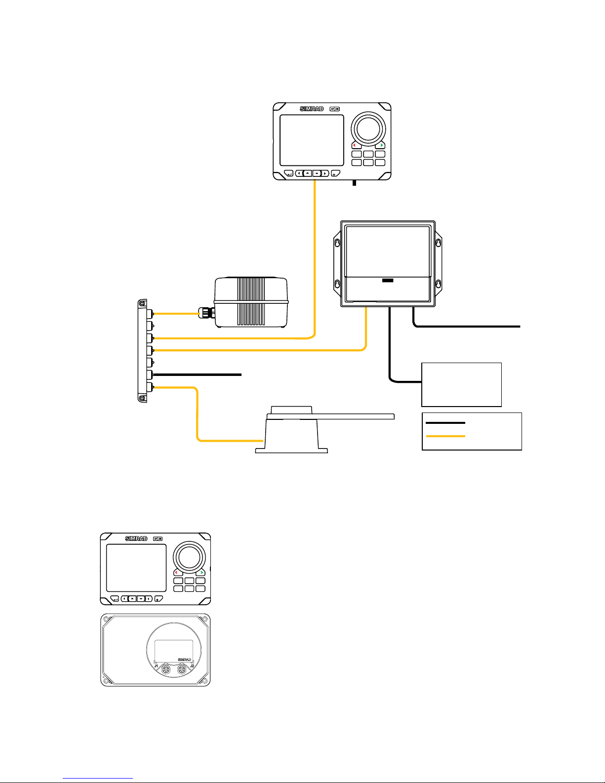
1.2 System components
12/24V Motor supply
Drive unit
Multijoiner
Compass
5,5 m
5 m
RF25 Rudder Feedback
12V SimNet supply
(SimNet cable without terminator)
Autopilot
Computer
Non SimNet
SimNet
Termination
plug
AP28
Control Unit
PWR
NAV WIN DTURN
STBY
DRIFT
NO-
AUTO
MENU
Figure 1-1 AP28 Basic system layo ut
1.3 AP28 Control Unit
PWR
NAV WIN DTURN
STBY
DRIFT
NO-
AUTO
MENU
A compact autopilot control for panel,
bulkhead or bracket mounting. A multifunction
LCD display with two-color backlighting
presents readout of autopilot and navigation
data, tactile keys, dedicated mode keys and
rotary course knob provide simple and precise
operation. It has two SimNet connectors for
system interconnection and control, expansion
and data sharing with other Simrad products.
A NMEA2000 Adapter Cable is available for
interface through a SimNet port.
Page 9

System description | 9
Multiple control units can be added to the system by
daisy-chaining or drop cable to the SimNet network.
1.4 Autopilot Computer
The autopilot computer is the main unit in the AP28
autopilot system. It contains the steering computer and
drive electronics for the drive unit motor and clutch and
provides interface to other system components. Two
models, AC12 and AC42 are available.
1.5 Rudder Feedback unit
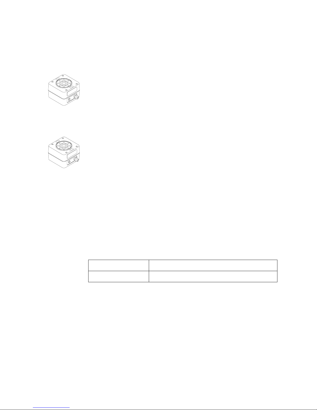
RF25 Rudder Feedback Unit
The RF25 is designed for connection to the SimNet
network. It comes with transmission link and 5 m (16
feet) of SimNet cable with connector.
The RF25 provides rudder angle output to a separate
rudder angle indicator also when the autopilot is
switched off.
RF300 Rudder Feedback Unit (optional)
The RF300 is designed for connection to the autopilot
computer. It comes with transmission link and 10 m (33
feet) of cable. RF300 has a different signal format and
does not offer the same accuracy as RF25.
With an RF300 as rudder feedback there is no output to
separate rudder angle indicators when the autopilot is
off.
Page 10
10 | System description
1.6 Heading Sensors
RC42 Rate Compass
RC42 is a fluxgate compass with an in tegra ted r ate o f
turn sensor. It provides a significa nt impr ovemen t to th e
dynamic performance of both the autopilot and a
stabilized radar display. A 5 m (16 feet) SimN et cable
with connector is attached.
FC40 Fluxgate Compass (optional)
This is a compact magnetic heading sensor using a
floating ringcore in a fluxgate coil. A 5 m (16 feet)
SimNet cable with connector is attached. The dynamic
performance is second to the RC42.
1.7 Optional equipment
See page 115.
1.8 Software record
When the system is switched on, a status display shows
the software version for the control unit. See page
14.
Software version
Description
SW 1.1.00. First issue
Page 11
Operation | 11
2 Operation
An autopilot is a very useful navigational aid, but
DOES NOT under any circumstances replace a
human navigator
Do not use automatic steering when:
• In heavy traffic areas or in narrow waters
• In poor visibility or extreme sea conditions
• When in areas where use of autopilot is prohibited by
law
When using an autopilot:
• Do not leave the helm unattended
• Do not place any magnetic material or equipment near
heading sensor used in the autopilot system
• Verify at regular intervals course and position of
vessel
• Always switch to Standby mode and reduce speed in
due time to avoid hazardous situations
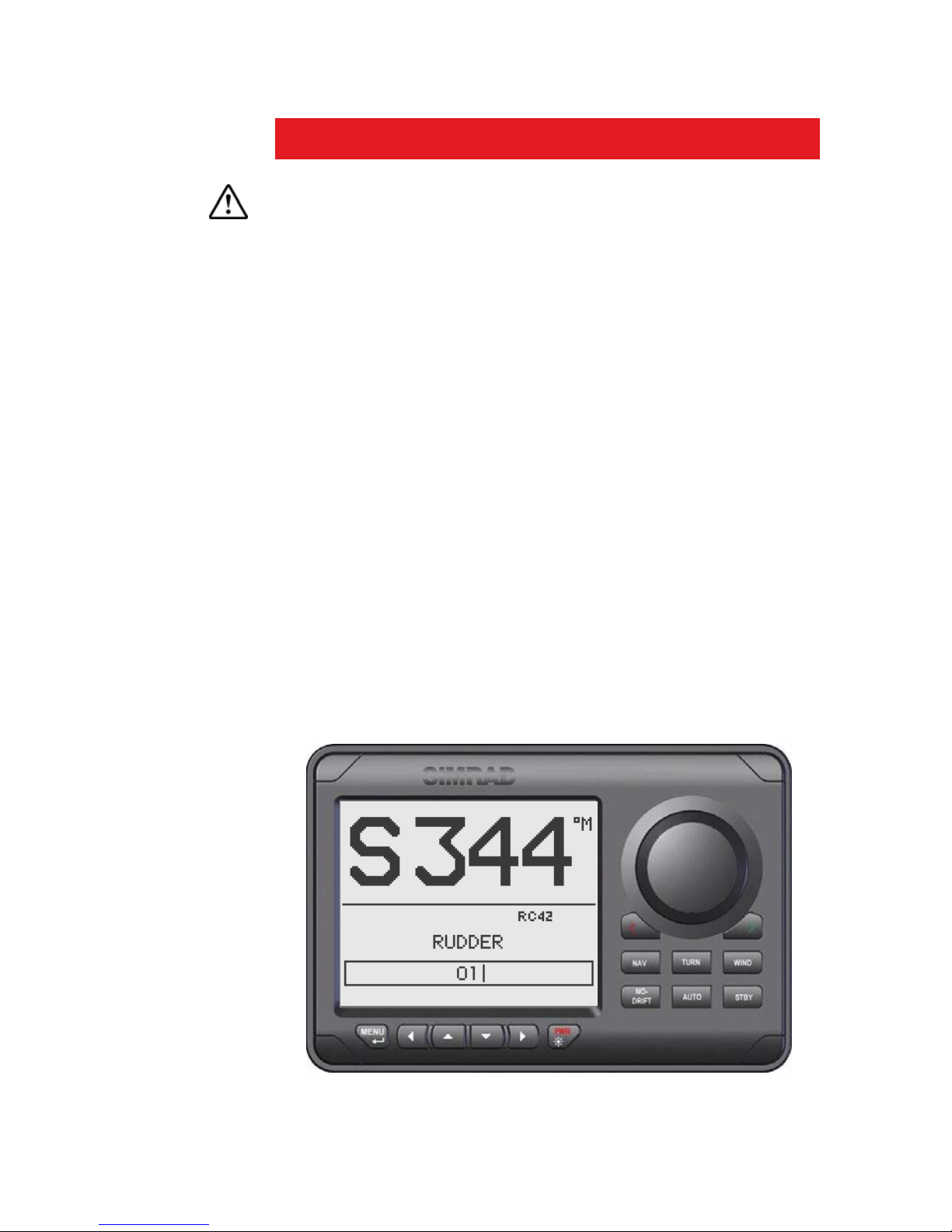
2.1 Overview
Figure 2-1 AP28 Front Panel
Page 12
12 | Operation
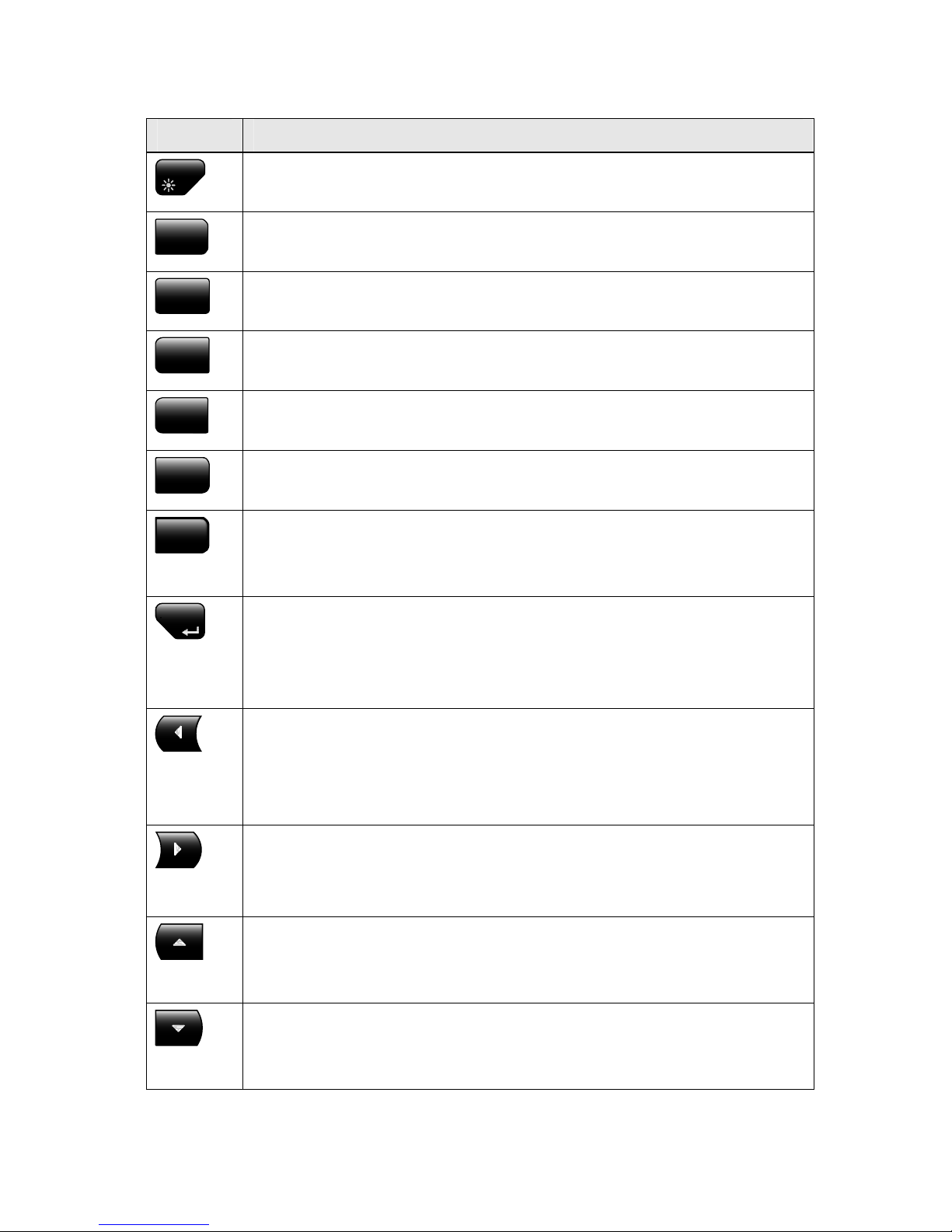
Key Description
PWR
Power ON-OFF / Light key
STBY
Standby key
Engage Standby mode
AUTO
Auto key
Engage Auto mode
NO-
DRIFT
NoDrift key
Engage NoDrift mode
NAV
Nav key
Engage NAV mode
WIND
Wind key
Engage Wind mode
TURN
Turn key
Enter turn sub-menu
Tack or gybe in Wind mode
MENU
Menu/Enter key
Enter Main Menu
Enter value, Confirm, O K
Action according to the softkey symbol
Left key
Back, Left, Cancel, Exit
Long press: Return to Main page (operation level 1)
Action according to the softkey symbol
Right key
Next, Right
Action according to the softkey symbol
Up key
Up in menu or list box, Increase
Action according to the softkey symbol
Down key
Down in menu or list box, Decrease
Action according to the softkey symbol
Page 13
Operation | 13
Port key
Adjust the commanded course or wind angle 1 or 10 degrees
Enable port power steering
Action according to the softkey symbol
Starboard key
Adjust the commanded course or wind angle 1 or 10 degrees
Enable starboard power steering
Action according to the softkey symbol
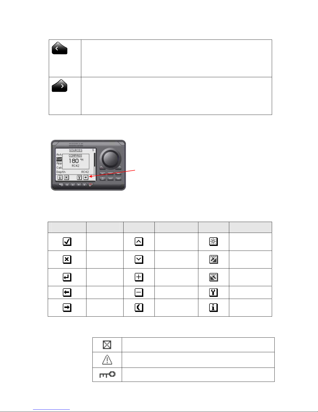
Softkeys
When the basic operation of the keys is
changed, softkey symbols will be displayed
right above the keys to indicate the
alternate function.
The following softkey symbols are used:
Symbol Action Symbol Action Symbol Action
Ok
Up
Increase
Day
backlighting
Cancel
Down
Decrease
Shallow to
stbd
Enter
Increase
Shallow to
port
Back
Decrease
Installation
Next
Night
backlighting
Present
information
Symbols
Inactive unit, disabled data page
Alarm reminder
Locked
Page 14

14 | Operation
Operational modes
The AP28 system is capable of the following primary
steering modes: STBY (power steering), AUTO, NoDrift,
NAV, WIND and WIND
NAV
. Each mode except WIND
NAV
have a dedicated key.
The WIND
NAV
mode can only be entered when in WIND
mode.
Each mode provides you with a multifunction mode
display.
User adjustable settings are found in the AP28 Main Menu
(page
51).
Alarms
Alarms are presented in plain text to alert you of system
and external data failure conditions. Alarms are both
audible and visual. The alarm listing is on page
111.
Transfer of command
In a multistation system the command can easily be
transferred from one unit to another by pressing the
active mode key.
AP28 units not in control will display the
icon.
Advanced operation
Refer to the Setup item in the Main Menu page 54 for
information.
2.2 ON/OFF
At first time turn on see page
69.
A single press on the PWR key turns the autopilot
system on and presents the start-up pages.
Page 15
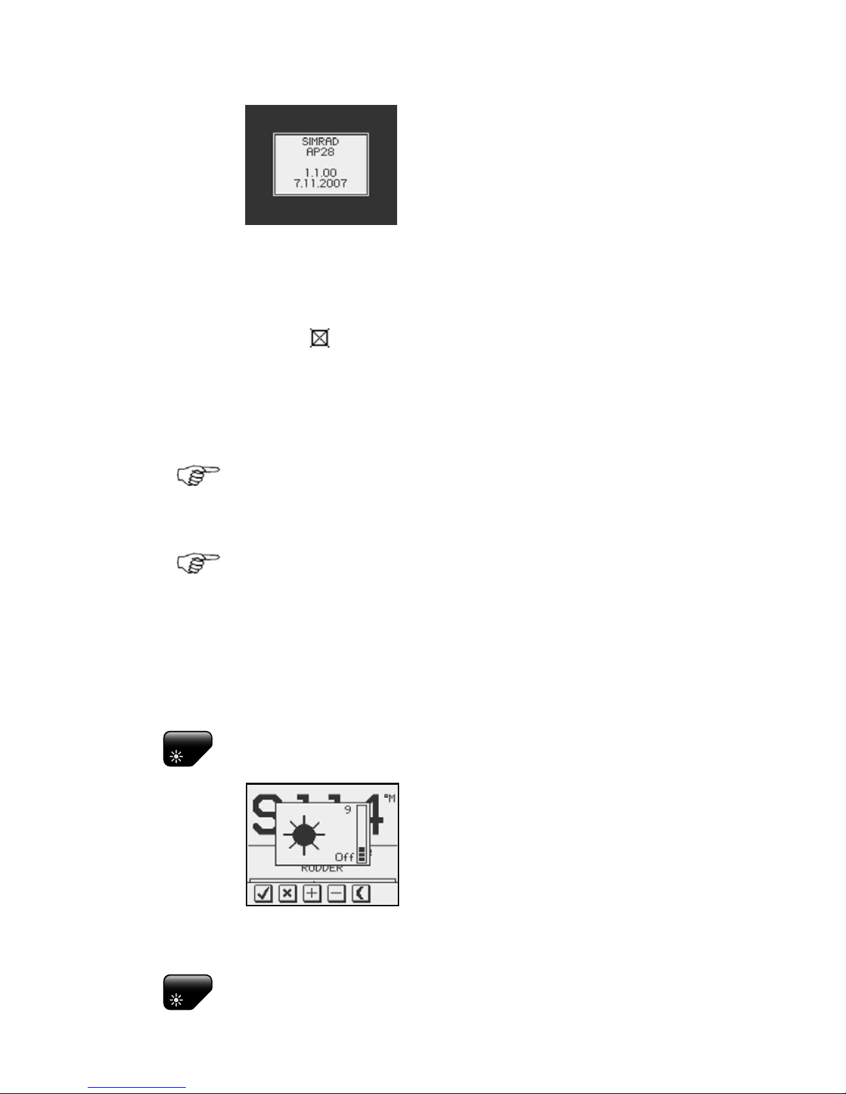
Operation | 15
• Product name
• Software version and release
date
Software version and release date are examples only.
After approximately 5 seconds, the system is operative
and the unit that was turned on will show the Standby
mode display. Other units in a multistation system will
display
. Control is transferred to any single unit by
pressing its STBY key.
A long press on the PWR key activates the power down
dialog box and the autopilot goes to STBY mode before it
is turned off after 3 seconds.
In an emergency it is possible, on a multistation system,
to turn OFF the system at any control unit by pressing
the PWR key.
Please note that even if the autopilot is turned off, a
small amount of current is drawn from the batteries
unless you throw the circuit breaker.
2.3 Backlighting
The display backlighting may be adjusted at any time.
PWR
1 Press the PWR key
- The Light level overlay window
will be displayed on top of the
current view
2 Press one of the keys as described below to change
the display backlighting:
PWR
a The PWR key to increase the light level by one
step
Page 16
16 | Operation
b The Up/Down softkeys to increase/decrease
the light level by one step
c The Day/Night softkey to toggle between day
and night profiles
If no adjustment is performed within 3 seconds, the Light
level overlay window will close.
For contrast and day/night settings, refer to page
60.
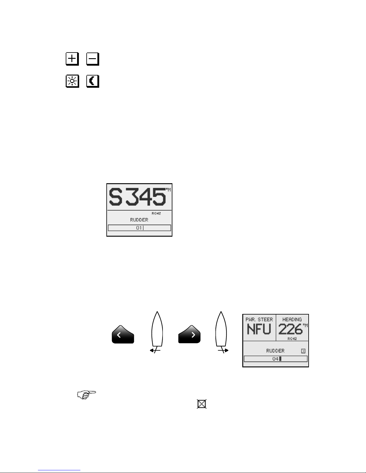
2.4 Standby mode
STBY mode is the mode that is used when steering the
boat at the helm.
Display informatio n :
• Standby mode
• Current heading 345°M
• Compass source: RC42
• Rudder angle 01° to stbd.
See page
80 about VRF.
Power steering (NFU)
In Standby mode, press any of the PORT or STBD keys.
The Non Follow-up (NFU) display is presented and the
rudder will move as long as the key is pressed.
Activates PORT
rudder command
Activates STBD
rudder command
When a NFU steering lever or remote control is operated,
other control units show (inactive). Refer to section 8
for operation of NFU steering levers or remote controls.
Page 17
Operation | 17
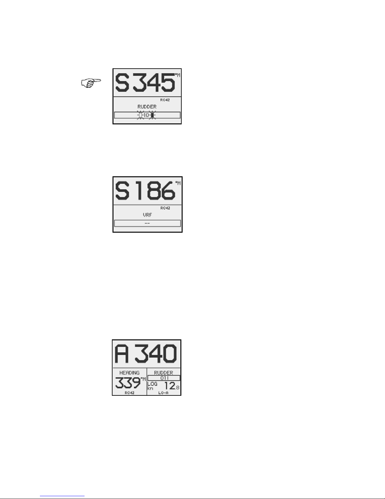
Alternating rudder angle bargraph
If your autopilot is driving a Simrad
MSD50 Stern Drive, the rudder
angle display will after turn-on
alternate between 10 degrees port
and starboard to indicate that the
(rudder) zero point need be set.
Refer to page
118 to set the zero point.
No rudder angle bargraph
When the autopilot is operating on
Virtual Rudder Feedback (VRF), the
rudder angle bargraph is empty.
2.5 Automatic steering
AUTO (Compass) mode
When the AUTO key is pressed, the AP28 automatically
selects the current boat heading as the set course and
maintains the rudder angle. This gives a bumpless
transfer at the mode change.
• Automatic steering mode
• Set course: 340 degrees
• Compass reading: 339°M
• Heading source: RC42
• Rudder angle: 01° to
starboard
• Speed: 12.8 kn (from log)
• Steering parameter set: LO-A
(Low automatic)
Page 18
18 | Operation
The AP28 will keep the boat on the set course until a new
mode is selected or a new course is set with the course
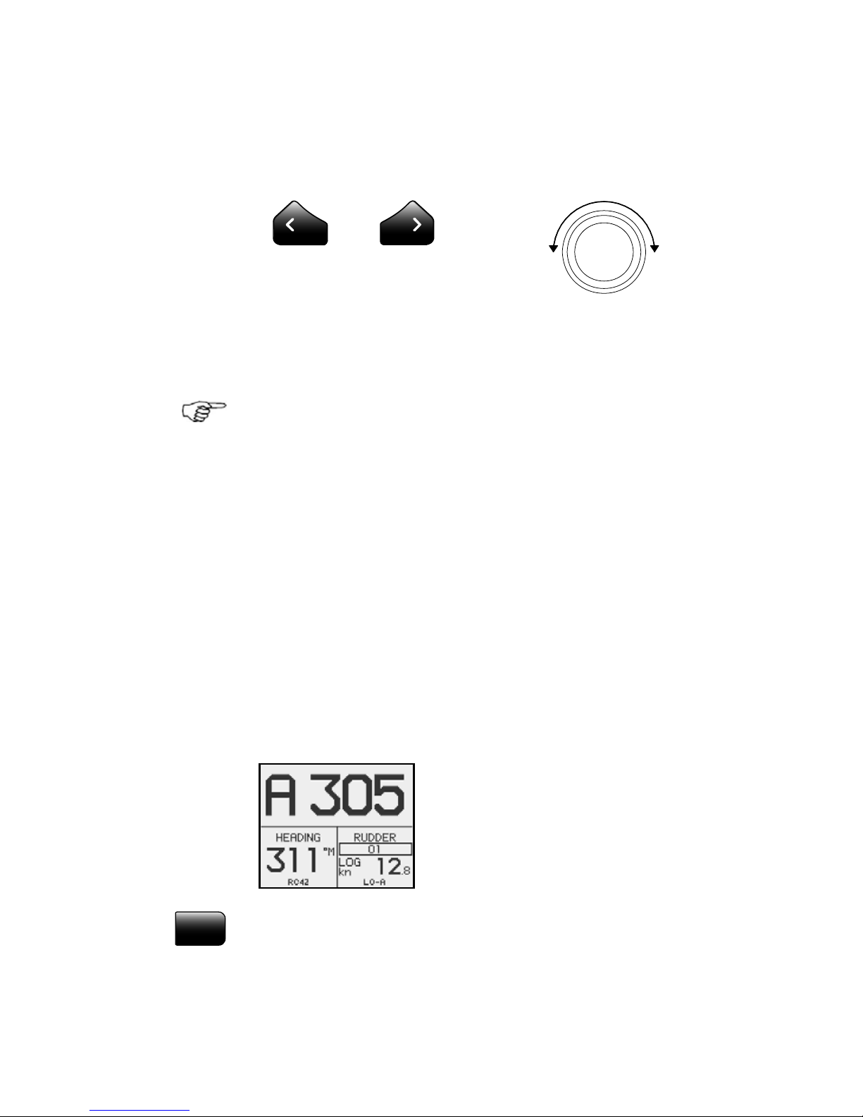
knob or the PORT or STBD keys. One revolution of the
course knob equals a 45° course change.
Decrease Increase
Course adjust 1°
(or 10°)/push
Course change
CCW: Decrease CW: Increase
On power boats you may in the Setup menu preset the
keys to change course by 10° per press (see page
165)
Once the course is changed to a new set course, the boat
will automatically turn to the new heading and maintain
the new course.
Heading capture
When in AUTO or NoDrift mode (page 36) heading
capture allows you to automatically cancel the turn you
are in by an instant press on the AUTO key or the
NoDrift key. The autopilot will cancel the turn to
continue on the heading read from the compass the very
moment you pressed the AUTO key or the NoDrift key.
This is a useful feature if you are not sure of the exact
turn you have to make to hit e.g. an inlet or a dock.
• Automatic steering mode
• New “captured” heading: 305°
• Compass reading: 311° M
(magnetic) or T (true)
STBY
Regain manual steering by pressing the STBY key.
Page 19
Operation | 19
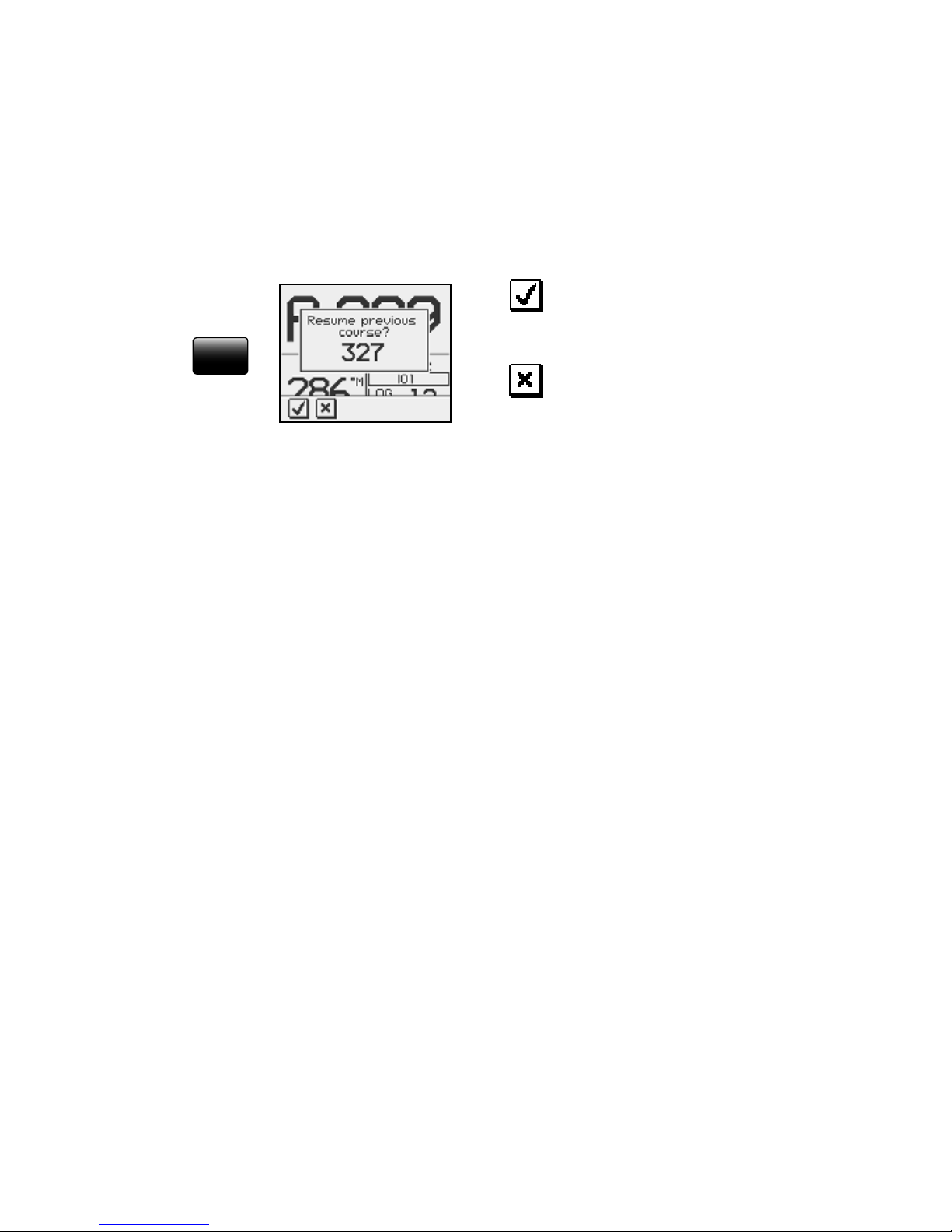
Dodging
The AP28 has no specific dodge key. Simply press STBY
and power steer or use the helm to pass any obstacle.
When you return to AUTO mode within 60 seconds the
following display is shown, offering two alternatives:
Go back to AUTO mode
on previous set course
AUTO
Go to AUTO mode with
current heading as set
course
If your dodging maneuver takes more than 60 seconds,
the autopilot will automatically continue on the current
heading.
Control of steering performance
When operating in an automatic mode the AP28 utilizes
two different sets of steering parameters (HI/LO). The
parameters control the response of the boat at different
speeds or wind directions. The two parameter sets can be
automatically or manually selected, and each set can be
manually adjusted (response adjust).
The speed at which the autopilot automatically changes
from LO to HI parameters (or opposite) is determined by
the "Transition Speed" set in the Installation/
Commissioning/Seatrial menu, page
89. See diagram on
next page.
At no speed input the autopilot defaults to LO steering
parameters when engaging an automatic mode from
STBY. This is a safety feature to prevent oversteering.
Page 20
20 | Operation
26
24
22
20
18
16
14
12
10
8
6
4
2
0
L
O
r
e
s
p
o
n
s
e
p
a
r
a
m
e
t
e
r
s
H
I
r
e
s
p
o
n
s
e
p
a
r
a
m
e
t
e
r
s
Transition Speed set to 9 Knots
Transition to LO parameters
with increasing s peed: 10 Knots
Transition to HI param eters
with decreasing s peed: 8 Knots
Speed
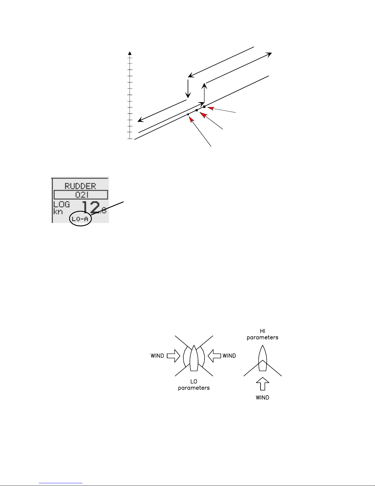
Display legend
HI-A High response parameters set automatically
LO-A Low response parameters set automatically
HI-M High response parameters set manually
LO-M Low response parameter set manually
Power boats
On power boats the automatic selection of HI or LO is
determined solely by the speed of the boat as shown in
the diagram above.
Sailboats
When sailing in WIND mode, the parameter set is
determined by the speed of the boat and the direction of
the wind as per below.
So if you loose too much speed e.g. when tacking, the
parameters will change to HI to gain sufficient rudder
response. This should be observed when setting the
transition speed on sailboats. See also
Wind response
on page
22.
Page 21
Operation | 21
Response adjust
The Autotune function in the AP28 is so refined that the
majority of boats will need no further adjustments of the
steering parameters. On some boats, however, or at
particular sea conditions a fine tuning of the steering
parameters may improve the performance of the
autopilot.
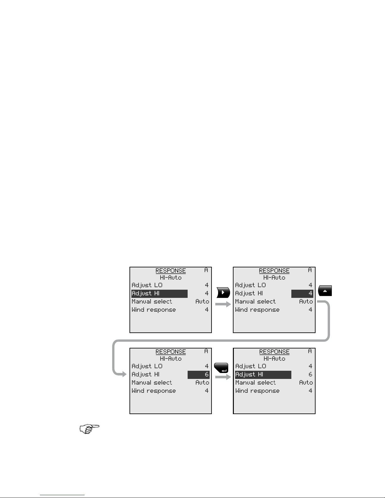
The Response control allows you to make this fine tuning
for each of the two (HI/LO) parameter sets. The response
can be set to nine levels. Level 4 is default with
parameter values as set by the Autotune function. If no
Autotune is made (not recommended) the level 4 values
are the factory default values.
A low response level reduces the rudder activity and
provides a more “loose” steering.
A high response level increases the rudder activity and
provides a more “tight” steering.
A too high response level will make the boat start S-ing.
When you access the RESPONSE page the highlighted
Adjust parameter is the one that is active.
MENU
Adjustment of HI and LO values can be performed even
with the boat out of the water.
Page 22
22 | Operation
Range Change per step Default
1-9 1 4
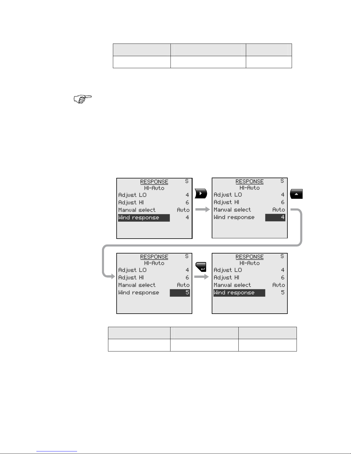
Wind response (sailboats)
Verify that the difference between Course To Steer (CTS)
and the actual heading is at an acceptable minimum.
If the difference between the set wind angle and the
actual wind angle is too big, increase the ‘Wind response’
to reduce the difference.
If the actual wind angle is S-ing around the set wind
angle, or the rudder activity is too high, the ‘Wind
response’ should be reduced.
MENU
Range Change per step Default
1-9 1 4
Page 23
Operation | 23
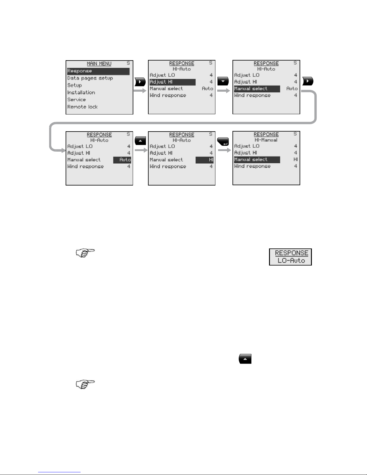
Selection of HI/LO parameters
MENU
The “Manual select” item has three alternatives:
Auto – HI – LO.
• Auto is automatically set by speed input
• HI or LO must be set manually when there is no
speed input
The sub-headline in the display shows the
active parameter set and how it is selected.
Pattern steering (power boats)
The autopilot offers a number of different pattern
steering features when in AUTO mode. There is a one
minute time-out between selecting a turn pattern and
starting the turn. During the time-out period the autopilot
will maintain the set course.
When steering in a turn pattern you may at any time
adjust the variables by pressing the
key.
To exit a turn pattern simply press the AUTO key.
Page 24
24 | Operation
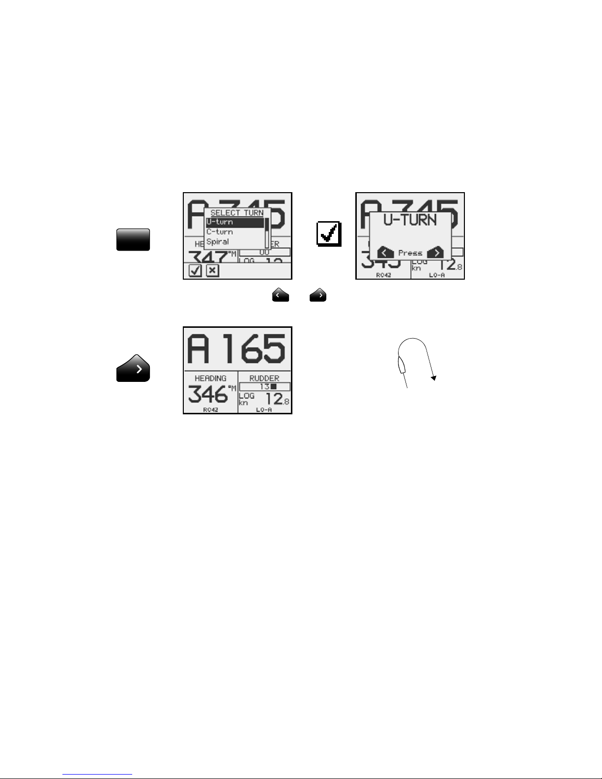
U-Turn
U-Turn changes the current set course to be 180 degrees
in the opposite direction.
This feature is very useful in a man overboard situation
and whenever you want to steer back on a reciprocal
heading.
TURN
Press either the or key to select the direction to
make the U-Turn and start the turn.
Boat makes starboard U-turn
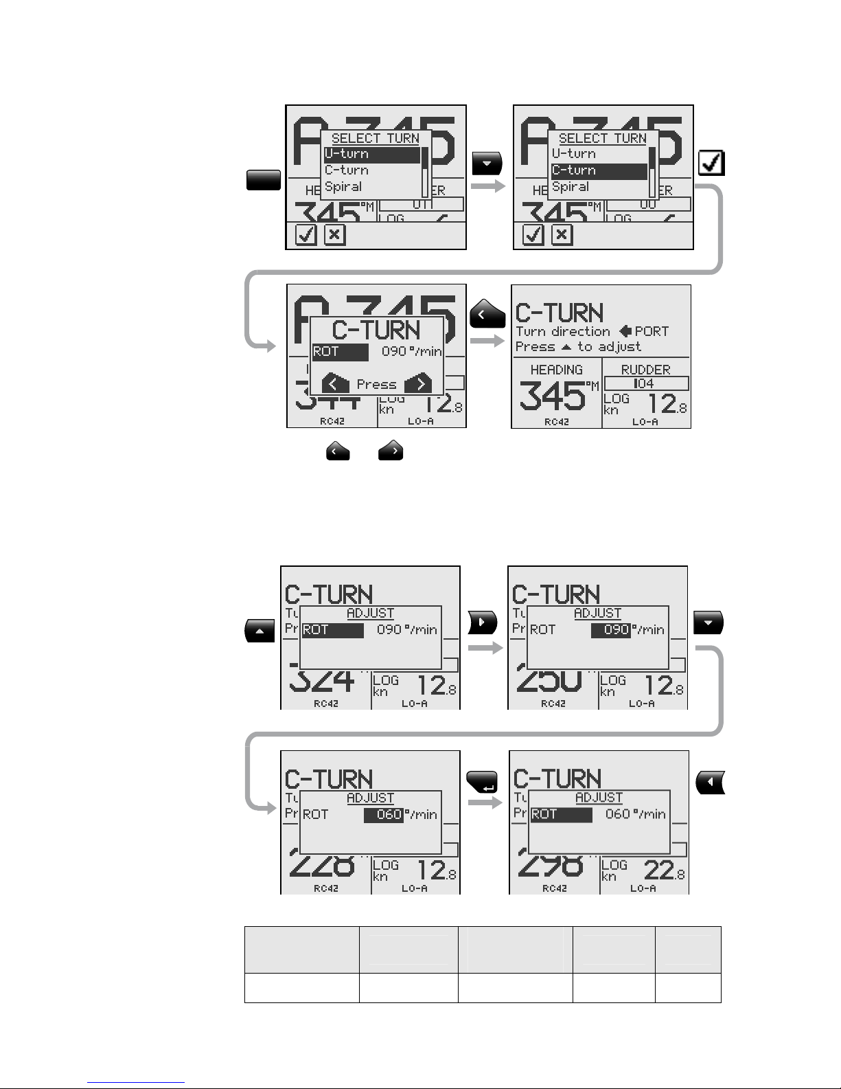
C-turn
The autopilot provides a continuous turn feature when in
AUTO mode. This may be used for circling fish or a
particular object on the seabed.
C-turn makes the boat turn in a circle with a constant
rate of turn. The user decides whether the C-turn should
be made to port or to starboard.
To enter C-turn mode:
Page 25
Operation | 25
TURN
Press the
or key to select the direction in which to
make the C-turn and start.
The turn rate (ROT) can be adjusted before the turn is
initiated and during the turn. Increasing the turn rate
yields to a smaller circle and vice versa.
MENU
Turn
parameter
Range
Change per
step
Default Units
Rate of turn 10 - 600 5 90 °/min
Page 26
26 | Operation
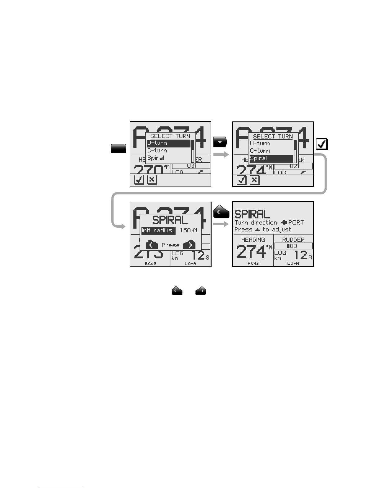
Spiral-turn
The spiral-turn feature may also be used for circling fish
or when searching a particular object on the seabed.
Spiral-turn makes the boat turn in a spiral with a
decreasing or increasing radius.
To enter Spiral-turn mode:
TURN
The “initial” radius can be set before the turn is started.
Press either the
or key to select the direction in
which to make the spiral-turn and start.
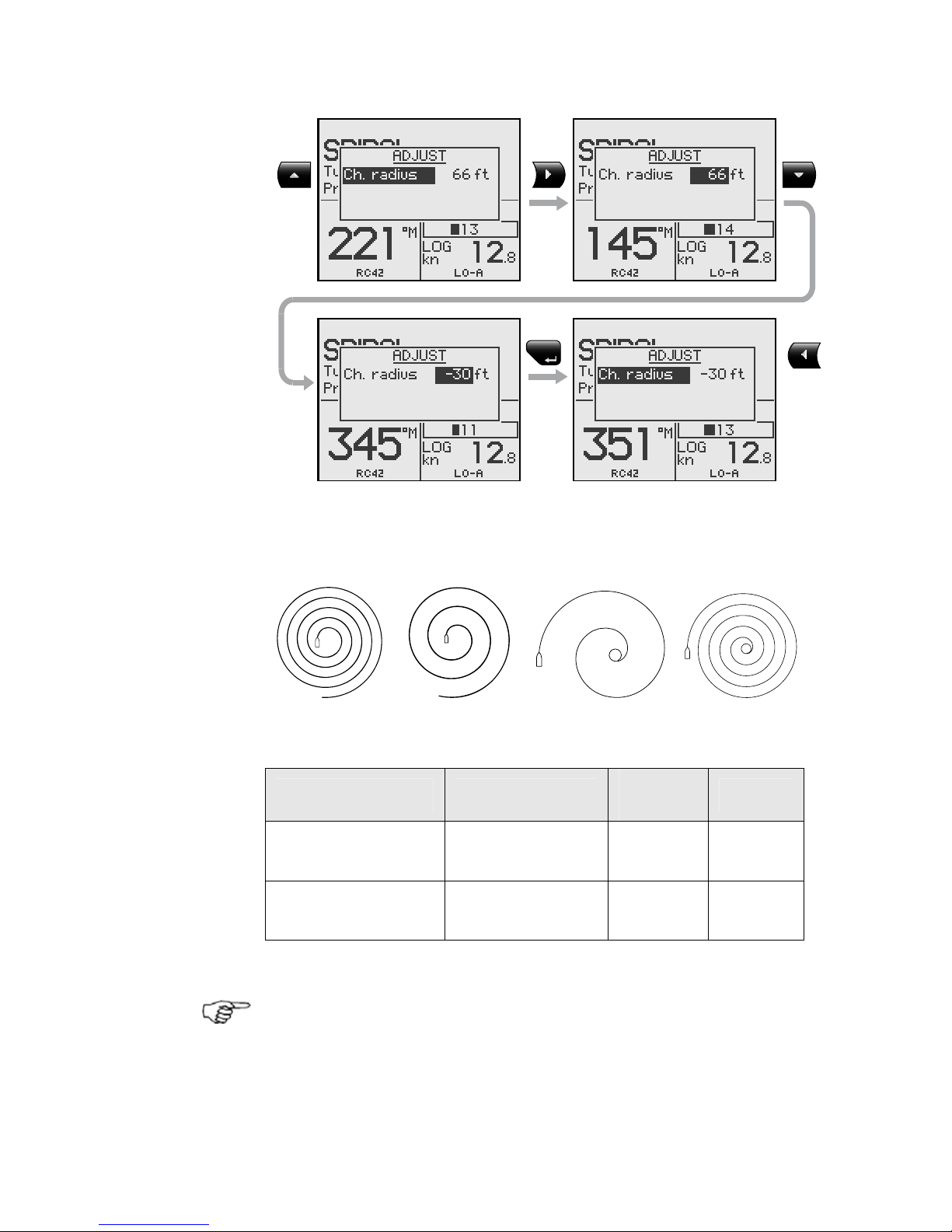
During the turn the “change in radius” can be adjusted
and the number of feet or meter is how much the radius
is changed for each circle turned.
If the “change radius” is set to zero, the boat will turn in
a circle.
Page 27
Operation | 27
MENU
Negative values indicate decreasing radius while positive
values indicate incr e a s ing radius.
Increasing radius Decreasing radius
Turn parameter Range
Change
per step
Default
Initial radius
33 ft - 3281 ft
10 m - 1000 m
10
10
164 ft
50 m
Change of radius
per turn
-164 ft - +164 ft
-50 m - +50 m
5
2
66 ft
20 m
The unit for radius is the same as the unit set for depth
(feet or meter).
Page 28
28 | Operation
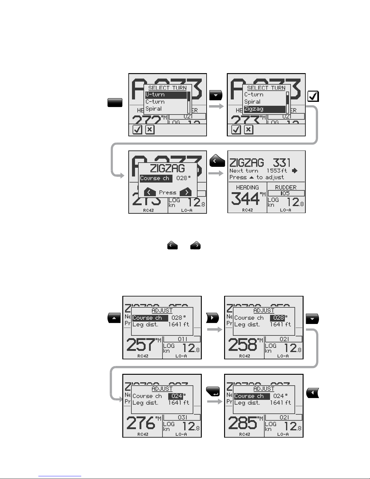
Zigzag-turns
To enter zigzag-turn mode:
TURN
The course change can be set before the turn is initiated
(2-70°).
Press either the
or key to select the direction in
which to make the first course change and start.
While sailing in a zigzag pattern you can alter the course
change, leg distance, and the main course. An arrow
shows the direction of the next course change.
MENU
Page 29
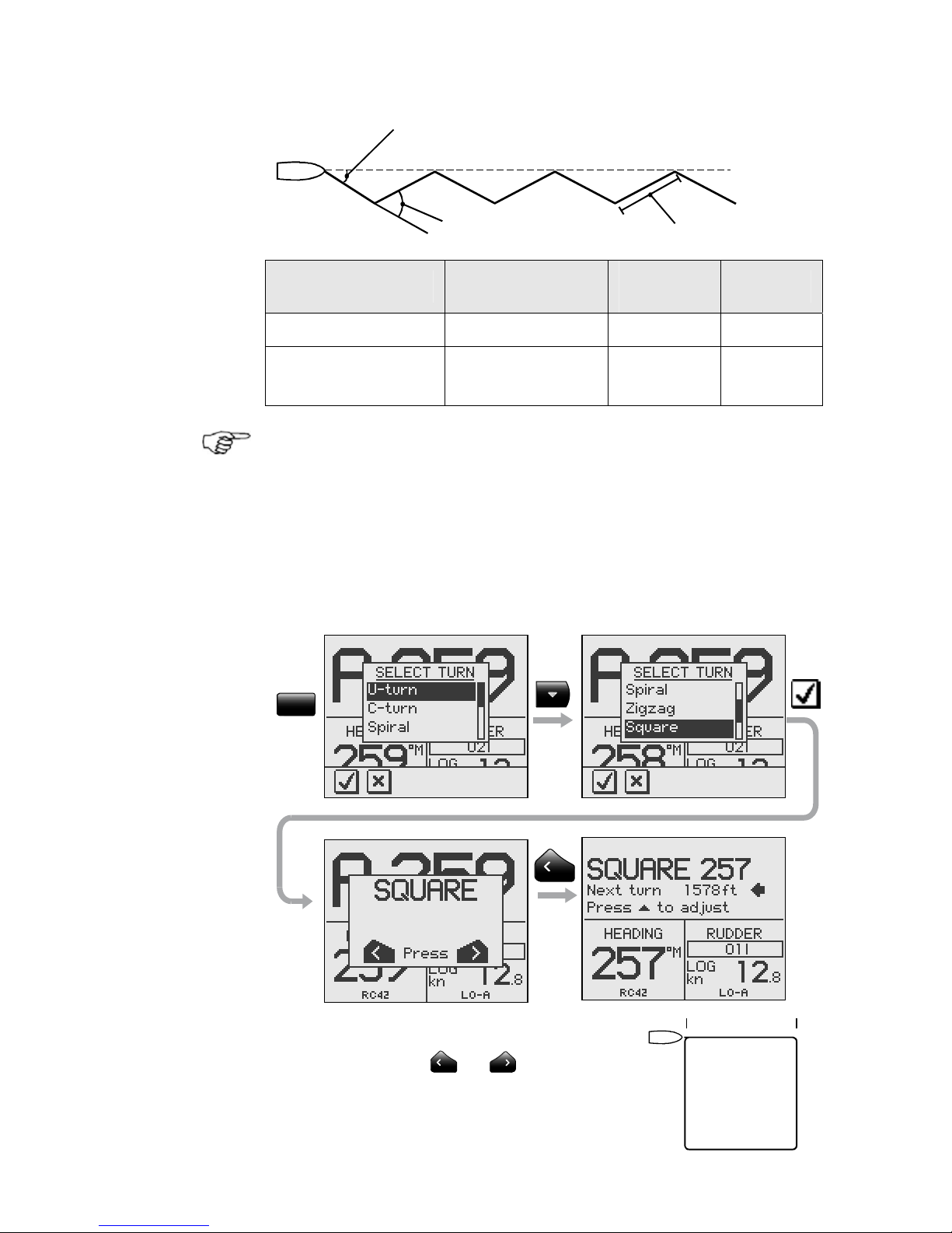
Operation | 29
Main course
Course change 40°
Initial course change 20°
Leg distance
Turn parameter Range
Change
per step
Default
Course change 4° - 140° 4 28°
Leg distance
82 ft - 9843 ft
25 m - 3000 m
50
25
1641 ft
500 m
The unit for leg distance is the same as the unit set for
depth (feet or meter).
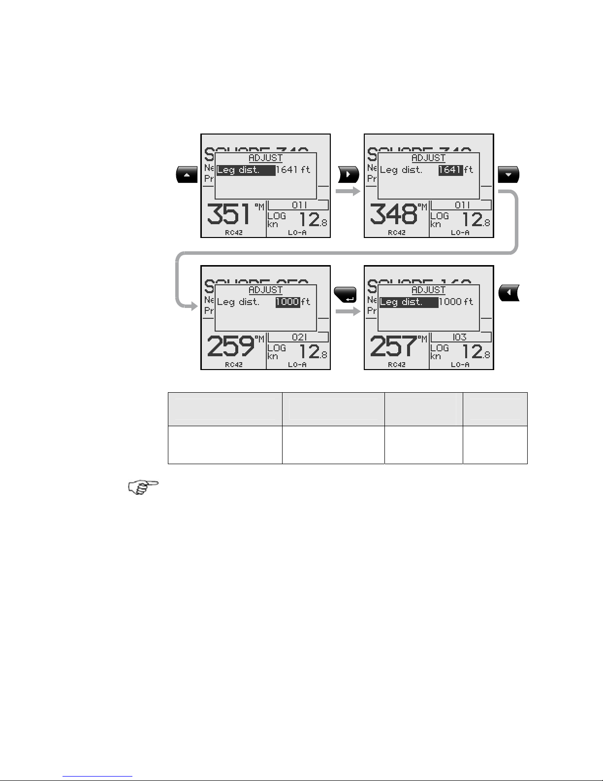
Square-turn
The square-turn feature in AUTO mode can also be made
as rectangle or any pattern where the next turn is 90°.
To enter Square-turn mode:
TURN
Press either the
or key to
select the direction in which to make
the first course change and start.
Leg distance
Page 30
30 | Operation
You can at any time change the main course.
You can also at any time change the distance of the leg
until the boat makes a new 90° turn.
MENU
Turn parameter Range
Change
per step
Default
Leg distance
82 ft - 9843 ft
25 m – 3000 m
50
25
1641 ft
500 m
The unit for leg distance is the same as the unit set for
depth (feet or meter).
Page 31

Operation | 31
Lazy S-turn
To enter Lazy S-turn mode:
TURN
The course change can be adjusted before the turn is
initiated (2-80°).
Press either the
or key to select the direction in
which to make the first course change and start.
While in a Lazy S pattern you can alter the course change
magnitude, turn radius and the main (average) course.
An arrow shows the direction of the turn.
Page 32

32 | Operation
Adjust course change and radius as follows:
MENU
Course change
Higher radius
Lower radius
Main course
Main course
Initial course change
Turn parameter Range
Change
per step
Default
Course change 4° - 160° 4 28°
Radius
16 ft - 1641 ft
5 m – 500 m
10
5
164 ft
50 m
The unit for radius is the same as the unit set for depth
(feet or meter).
Page 33

Operation | 33
Depth Contour Tracking, DCTTM
With input from an echo sounder, the autopilot can be set
to steer the boat to a set depth. This is very useful if you
want to follow a depth contour. Make sure you have
depth reading available in the system.
Smooth seabed Rocky waters
Slope Narrow channel Ridge
Do not use this feature unless the seabed is
suitable. Do not use it in rocky waters where the
depth is varying significantly over a small area.
TURN
Page 34

34 | Operation
The actual depth reading is shown on the display.
Steer the boat to the depth you want to track and in the
direction of the depth contour (main course). When the
wanted depth is shown in the display, activate the depth
contour steering with the
or softkey (any of the
two). Use the
key when it is shallow to port or the
key when it is shallow to starboard.
Main course
This should be the main (average) direction of the depth
contour you want to follow. If the contour line is making
a big change in direction, you should manually adjust the
set course to the new direction. This will result in a
quicker response from the autopilot. If the course is not
adjusted, the autopilot will need more time to turn and
steer the boat back to the reference depth.
The sub screen has the following adjustments:
Depth gain
The autopilot is tracking the depth by computing an xtrack error when the boat is off the reference depth. This
error automatically adjusts the set course to bring the
boat back on track.
Use the gain control to have a firm or smooth response to
the variation in depth.
MENU
Page 35

Operation | 35
Contour Cross Angle (CCA)
With this parameter you can make the boat lazy s across
your reference depth. With the CCA set to zero there is
no S-ing. The CCA is an angle that is added to or
subtracted from the set course. Each time the boat
crosses the reference depth, the sign (+/-) of the CCA is
changed and makes the boat turn to cross the reference
depth contour in the opposite direction. The larger the
CCA the bigger the turn.
Turn parameter
Range
Change
per step
Default
Main course 0° - 359° 1 –
Depth gain 5 - 95 5 5
Contour Cross Angle 0 - 50 1 0
Reference depth
The reference depth is captured when the DCTTM is
activated. To change the reference simply use the Up or
Down key.
CCA set to 15 degrees.
Approaching reference
de
p
th from starboard
CCA set to 15 degrees.
Approaching reference
depth from port
Reference
de
p
th
Page 36

36 | Operation
Tacking in Auto mode (sailboat)
The tack function is only available when the system is set
up for SAIL boat type in the installation setup.
Tacking in AUTO mode is different from tacking in WIND
mode. In AUTO mode the tack angle is fixed and can be
set in the Setup/Sailing menu. Default tack angle is
100°.
Tacking should only be performed into the wind and must
be tried out in calm sea conditions with light wind to find
out how it works on your boat. Due to a wide range of
boat characteristics (from cruising to racing boats) the
performance of the tack function may vary from boat to
boat. Except for the fixed course change and the
difference in displays, the procedure is similar to that of
the U-Turn described on page
22.
TURN
2.6 NoDrift mode
The NoDrift mode is an alternative to route steering in
NAV mode, and is automatically entered when you press
the NODRIFT key.
The data source when operating in NoDrift mode is the
Position (Pos) source. To operate in NoDrift mode your
GPS/chart plotter must be turned on.
Boat makes
starboard track
For
sailboat
only
Page 37

Operation | 37
Unlike when in Auto mode the autopilot will steer the
course unaffected by wind and current when the NoDrift
mode is engaged.
The course to steer to (bearing line) can be changed the
same way as when changing course in Auto mode.
NO-
DRIFT
• Compass heading: 345° M.
• Rudder Angle: 01 to starboard
• Speed: 12.8 kn from the log
• Steering parameter: LO-A
2.7 Navigating with the AP28
The AP28 has the capability to use steering information
from an external navigator (GPS, Chart Plotter) to direct
the boat to a specific waypoint location, or through a
route of waypoints. The information received from the
navigator automatically changes the course to steer to
keep the boat on the track line and direct the AP28 to the
destination waypoint.
If the AP28 is connected to a navigation receiver that
does not transmit a message with bearing to next
waypoint, it will steer on Cross Track Error (XTE) only. In
that case you have to revert to AUTO mode at each
waypoint and manually change set course to equal
bearing to next waypoint and then select NAV mode
again.
To obtain satisfactory navigation steering, the following
points must be fulfilled prior to entering the NAV mode:
• The AP28 autosteering must be tested and determined
satisfactory
• The navigation receiver (GPS, Chart Plotter) must be
in full operating mode with adequate signal
characteristics for valid position and navigation data
• At least one waypoint must be entered and selected as
the current “Go to” waypoint
Page 38

38 | Operation
The data source when operating in NAV mode is the
Navigation (Nav) source. It is normally the same as the
Position source (GPS/Chart plotter) see page 57.
Navigational steering should only be used in open waters.
When selecting NAV mode, the AP28 maintains the
current set course and prompts the user to accept the
course change towards the destination waypoint.
Press the NAV key to activate the NAV prompt display.
NAV
The prompt display shows the
name of the next waypoint (WP),
the bearing of the track line
(BWW) from the previous
waypoint to the destination
waypoint, the required course
change (CHG) and the direction
in which the boat will turn.
If only one waypoint has been entered the bearing will be
from the present position to the destination waypoint.
• NAV mode
• Course to steer (CTS): 005 is
set internally by the autopilot
to steer the boat onto the track
line and maintain the bearing
• Cross Track Error (XTE): 1.315
nm
• Boat symbol illustrating whether the boat is to port or
starboard of planned track
• Compass heading: 350° M
• Next waypoint: WP1
• Speed over ground (SOG): 12.8 kn
• Distance to next waypoint (DTW): 14.29 nm
• Steering parameter: LO-A
Page 39

Operation | 39
For Cross Track Error, the number of decimals shown
depends on the output from the GPS/chart plotter. Three
decimals give a more accurate track keeping.
When operating the AP28 in NAV mode to steer through a
route of waypoints, the AP28 will steer to the nearest
waypoint in the direction of the route after you accept the
NAV mode prompt. When you arrive at the waypoint, the
AP28 will output an audible warning, display an alert
screen with the new course information, and
automatically change course onto the new leg.
If the required course change is more than the NAV
change limit (default 10
°
), you have to verify that the
upcoming course change is acceptable. This is a safety
feature. See page
79 on how to change the ‘NAV change
limit’.
Alert screen
Press the
softkey to
verify course change
larger than 10°.
If no verification is made,
the AP28 will continue on
the current set course in
AUTO mode.
STBY
Regain manual steering by pressing the STBY key.
Page 40

40 | Operation
Setting the waypoint arrival circle
For route navigation it is recommended to use automatic
waypoint shift at a set waypoint arrival circle.
The arrival circle should be adjusted according to boat
speed. The higher the speed, the wider the circle. The
intention is to make the autopilot start the heading
change in due time to make a smooth turn onto the next
leg.
The figure below may be used to select the appropriate
waypoint circle on the GPS/chart plotter.
Example: With the speed of 20 knots you should use a
waypoint circle with radius 0.09 nm.
The distance between any waypoints in a route must not
be smaller than the radius of the waypoint arrival circle
when using automatic waypoint shift.
Page 41

Operation | 41
Selecting a different navigation source
If you have more than one navigator connected to the
AP28, you will be able to choose any for navigation. Refer
to the ‘Sources’ item in the Setup menu for details on
how to select a different navigator (page
58).
2.8 Wind vane steering (sailboats)
The WIND mode is only available if the system has been
set up for SAIL-boat in the Installation Menu.
Prior to entering WIND mode the AP28 system should be
operating in AUTO, with valid input from the wind
transducer.
Enter the WIND mode by pressing the WIND key.
The wind display presents the following information:
WIND
• Wind (vane) mode
• Set wind angle: 008 degrees
from starboard
• Measured wind angle: 008°A
(apparent) or T (true)
• Course to steer (to maintain
set wind angle): 345°
• Heading: 344° M (magnetic) or T (true)
• Rudder angle: 00° to starboard
• Speed from log: 12.8 kn
• Parameter: LO-A (Low value, automatic set)
The set course to steer (CTS) and set wind angle are
entered from the compass heading and the wind
transducer at the moment the WIND mode is selected.
From that point the autopilot will change the course to
maintain the wind angle as the wind direction may change.
If the cumulative shift of the wind direction exceeds a set
limit a WIND SHIFT alarm will sound.
Page 42

42 | Operation
Adjustments to the set wind angle is as per below.
Steer port Steer stbd
Adjust set wind angle
1°/ push
Major wind angle adjust
CCW: Steer port CW: Steer stbd
STBY
Regain manual steering by pressing the STBY key.
Tacking in Wind mode
Tacking in WIND mode as compared to AUTO mode can
be performed when sailing with apparent or true wind as
the reference; the true wind angle should be less than 90
degrees.
The tacking operation will immediately mirror the set
wind angle to the opposite side of the bow. A tack
window will appear on the display. The rate of turn during
the tack will be given by the ‘Tack time’ parameter set in
the Setup/Sailing menu (page
63). The tack time is also
controlled by the speed of the boat to prevent loss of
speed during a tack.
A quick press on the TURN key will activate the tack
function and the boat will start turning to the opposite
wind angle.
A new press on the TURN key after the Tack window
appears, will interrupt the tack operation
and the boat will
return to the previous set wind angle.
Page 43

Operation | 43
TURN
Gybing
Gybing is possible when the true wind angle is larger
than 120°.
TURN
The time to make a gybe is determined by the speed of
the boat to make it as quick as possible within control.
Tack and gybe prevent
When beating and running, using the autopilot is most
critical.
If the sails are unbalanced when beating, yaw forces from
the sails can drive the boat into the wind. If the boat is
driven beyond the set minimum wind angle (see page
96), the thrust from the sails will suddenly disappear and
Page 44

44 | Operation
reduces the boat speed. Hence the boat will be more
difficult to steer because the rudder will become less
effective.
The tack prevent function in WIND mode has been
implemented to avoid such situations. It will react
immediately when the apparent wind angle becomes 5°
less than the set minimum wind angle, and more rudder
will be commanded.
When running, it is difficult to steer the boat with waves
coming sideways or from behind. The waves may yaw the
boat into an unwanted gybe; this can be hazardous for
both the crew and the mast.
The gybe prevent function will be activated when the
actual apparent wind angle becomes greater than 175° or
gets opposite to the set wind angle. More rudder will be
commanded to prevent an unwanted gybe.
The tack and gybe prevent functions are not a
guarantee against getting into a hazardous
situation. If the effect of the rudder and/or drive
unit is not adequate, it may happen. Pay particular
attention in such situations.
Page 45

Operation | 45
Blank page
Page 46

46 | Operation
2.9 Wind steering and navigation
(sailboats)
The autopilot can also steer the boat given both wind
data and track data from a GPS/chart plotter. In this
mode called WIND
NAV
mode the automatic steering is
based on a set of criteria (see below). Wind steering and
navigation is activated by pressing the NAV key when in
Wind mode [1]. The initial course change (CHG) needed
to navigate towards the active waypoint, is calculated by
the autopilot. The autopilot will utilize the current wind
direction in these calculations and the change of course is
accepted by pressing the
softkey [2].
Operating in WIND
NAV
mode
Refer to Figure 2-2 which shows a scenario with a
sailboat that enters Wind
NAV
mode to sail the most
efficient way to waypoint WP1.
1. The autopilot is still in Wind mode approaching
mark 2 and waypoint WP1 has been entered on the
chart plotter.
2. The Wind
NAV
mode is entered and the autopilot
prompts confirmation for a course change of 71
degrees to starboard.
3. The boat is now on the leg to mark 4 where a
starboard tack is required to avoid running on
ground. The distance to tack DTT is displayed and
so is VMG to wind. Furthermore the autopilot
displays course to steer and heading.
4. The tack has been initiated on the autopilot and the
tack display is presented.
5. The autopilot now presents you with information
about the new leg and the next tack.
6. You are about to cross the layline and the autopilot
“recommends” a new tack to Port.
7. The new tack is performed.
Page 47

Operation | 47
8. You are on the last leg directly to the waypoint. The
autopilot is now keeping the boat on track (XTE)
and displays bearing and distance to the waypoint.
Figure 2-2
Page 48

48 | Operation
2.10 Data pages
A number of data pages can be displayed if the
information is available on SimNet (see page
109).
When one of the main mode pages are displayed, access
and scroll through the available data pages by pressing
the Up/Down keys.
When accessing the data pages, the last active data page
will be shown first.
If you prefer to change the number of instrument pages
to be available; access the Main menu/Data pages
setup.
When displaying data pages the left hand side of the
screen will show the following information depending on
mode:
Standby
mode
Heading
Heading
source
Auto mode
Set course
Heading
Heading source
LO parameters,
set automatically
Nav/NoDrift mode
Course to steer
Cross Track Error
(XTE)
LO parameters,
set automatically
Wind mode
Set wind angle
Actual apparent
wind angle
LO parameters,
set automatically
Wind
NAV
mode
Layline steering
Set wind angle
Actual apparent
wind angle
LO parameters,
set automatically
Page 49

Operation | 49
Available data pages
2.11 Multiple station system
In normal operation control is accessible from every
control unit connected to the AP28 system. One control
unit is "active" and provides the
user with access to all functions.
All remaining control units are
"inactive" and have no effect on
course changes. A single press on
any of the mode keys on an
"inactive" control unit will allow
transfer of command and make it
"active".
Inactive unit
Main mode screen
Page 50

50 | Operation
Blank page
Page 51

Main menu | 51
3 Main menu
In the Main menu you will find items for operation, setup
and installation of the autopilot. The Service menu item
presents you with various system information and access
to the Demo mode.
Response
Data pages setup
Setup
Installation
Service
Remote lock
Enable/Disable
Restore data pages
Damping
Alarms
Sources
Display
Language
Units
Seastate fil ter
Sailing
Course adjust
Commisioning
Automatic steering
Calibration
Boat type
Rudder drive
SimNet config
SimNet status
System data
Resets
Demo
About AP28
Dockside
Seatrial
Comm. status
Transition spd
Autotune
Recall autotuned
Steer to compass
Steer to wind
Steer to navigator
Boat speed
Depth
Apparent wind
Compass
Rudder feedback
Virtual feedback
SimNet groups
Instance number
Autopil o t r es e t
Global reset
Boat type
Rudder feedback
Virtual feedback
Drive voltage
Drive engage
Rudder test
Depth calibration
Steer to wind
Steer to navigator
Set rudder 0
Compass calibration
Wind calibration
Boat speed calib
Transition spd
Autotune
Calibrate w/SOG
SPD correction
Offset
Offset
Calibrate
Offset
Max stbd/port
Set rudder 0
MAIN MENU LEVEL 2 LEVEL 3 LEVEL 4
Page 52

52 | Main menu
The main menu is activated by a press on the MENU key.
The main menu items give further access to sub menus
and parameter settings.
Parameter settings are usually presented to the right, but
may also be listed in an overlay window.
Unit settings presented in
the window’s right column
Language settings presented
in an overlay window.
The keys are used as follows to navigate in the menu
system:
KEY SINGLE PRESS PRESS AND HOLD
MENU
Confirm a selection/parameter
setting
Go to next menu level/
parameter settings
Go to previous menu level/
parameter listing
Return to active mode
display
Go to previous/next menu item,
increase/decrease parameter
value
3.1 Data pages setup
All available data pages are enabled as default. See page
49. If you prefer to have less data pages available, pages
may be disabled.
Page 53

Main menu | 53
Disabling pages
Continue to select pages and repeat the procedure if
more pages are to be disabled.
Press and hold the Left key to leave the menu and
return to last active page.
Enabling pages
A disabled page is only visible when
using the Enable/disable command.
A disabled page is indicated with a
crossed rectangle.
Continue to select pages and repeat the procedure if
more pages are to be enabled.
Press and hold the Left key to leave the menu and
return to last active page.
Page 54

54 | Main menu
Restore all pages
To restore all disabled data pages, select Restore data
pages:
3.2 Setup menu
The Setup menu contains items that the user may want
to use on a less regular basis.
The following items are described:
- Changing the damping factors
- Alarm setup
- Automatic and manual source selection
- Changing the display settings
- Language selection
- Setting the units of measure
- Adjusting the seastate filter
- Changing the sailing parameters
In this section it is assumed that the user is familiar with
how to use the keys and how to maneuver in the menus.
If not, refer to Main menu, page 51 onwards.
Page 55

Main menu | 55
Damping
The damping factor indicates how fast the display will
respond to changes.
The higher the damping factor the more stable display
reading on the instrument.
Damping of the apparent wind angle is made by the
Advanced Wind Filter (AWF) in the Autopilot Computer.
Increasing the ‘Wind damping’, will make the AWF output
depend more on heading and boat speed. Decreasing the
‘Wind damping’, will make the AWF depend more on the
“raw” apparent wind angle data.
The speed input to the AWF is Speed Over Ground (SOG).
If SOG is not available, the AWF will use speed through
water. If none of these are available, the AWF will use a
boat speed that is 1.5 times the Transition Speed.
Range Change per step Default
0 - 9 1 4
Page 56

56 | Main menu
Alarms
The AP28 may be set up to sound an alarm if vessel or
environmental parameters exceeds preferred values.
The alarm monitoring is disabled by setting the value to
Off.
Shallow water
The setting of the alarm is global and can be made on
any Simrad unit that has this function implemented.
Range Change per step
Default Units
Off – 320 ft
(Off – 100 m)
1.6 – 5: 0.1 ft
5 – 10: 0.5 ft
10 – 50: 1 ft
50 – 100: 5 ft
100 – 320: 10 ft
(0.5 – 5: 0.1 m)
(5 – 10: 0.5 m)
(10 – 50: 1 m)
(50 – 100: 5 m)
Off ft, m
Wind shift
The wind shift alarm monitors the wind angle. The
reference angle is set when the alarm is turned on and
when the product is turned on. The reference wind angle
is reset to present wind angle when the commanded (set)
wind angle is changed on the autopilot and when a wind
shift alarm is acknowledged.
The wind shift reading is presented on the ‘Wind shift’data page and shows the change of wind angle with
reference to the (geographic) wind direction.
Page 57

Main menu | 57
Range Change per step
Default
Off, 5-90° 1 Off
Alarm status
Displays a list of present alarms
Sources
A data source can be a sensor or a device connected to
SimNet providing data to other SimNet devices. Data can
be of different type such as compass data, apparent wind
data, calculated wind data, depth data, etc. A given data
type will only be provided from one
device to the other
devices organized in a SimNet Source group (Ref.
Installation/ SimNet groups, page
100).
At the first time turn on of a group of SimNet
interconnected products (SimNet Source Group), data
sources are automatically selected from an internal
SimNet priority list. If a data source is connected to
SimNet after the first time turn on, this will be identified
and automatically selected if no other data source already
is selected for the given data type.
It is only required to update the SimNet source selections
if an alternative source is made available for a given data
type and this source has not been selected automatically.
The data types and their
respective data sources used in
the products are listed on the
source page in the products.
If no selection is made for a data type, ‘- - -‘ is displayed
instead of the device name or acronym.
SimNet will automatically select Position source and
Navigation source from the same GPS/Chart plotter. If
you want them to be different you have to change them
manually.
Page 58

58 | Main menu
Automatic source update
The Auto select function is mainly for situations where
the automatic source selection needs to be updated
because a selected data source is not supplying data or
has been physically replaced with another one. The
update secures that the existing source selections are
valid and maintained. Missing sources are either
automatically exchanged with an alternative source from
the list of available sources for the given data type or the
replacing source is selected. If a source is no longer
available for the given data type, the display will show
‘- - -‘ instead of the source acronym.
If more than one source is found for each data type, the
preferred source may be manually selected.
Manual source selection
Data sources can also be selected manually. All devices
providing data of the given type will be listed in a device
list. Highlight the data type and press the
key to
display the list of available devices.
Confirm selection of the highlighted device.
Exit without selec t in g
Page 59

Main menu | 59
See information about the selected
data source.
For data types which can be calibrated, an overlay screen
displaying the data from the selected data source will
appear first (Ref. Installation/Calibration).
Enter the Calibrate and Offset
menu.
(Ref. Installation/Calibration).
Proceed to display a list of
available sources for the given
data type.
Display
The display is controlled by the Contrast setting and two
user profiles that can be individually adjusted.
For each profile you can:
- Adjust light level
- Adjust the light color
- Invert the display
Page 60

60 | Main menu
The profiles are Day profile and Night profile. The
profiles can be optimized for readability under different
light conditions, and you can quickly switch between the
two using the PWR key and the
softkeys. Refer to
Backlighting, page 15.
Display contrast
The contrast controls the difference between the
text/graphics and the display background. Level 9 gives
the highest contrast.
Range Change per step Default
0 - 9 1 4
Day and night profiles
The day and night settings controls the display
background, the light color and light level for the display
and the keys.
Page 61

Main menu | 61
Setting Range Change per step
Default
Light level Off – 9 1 3
Light color White/red -
White (Day)
Red (Night)
Invert
display
Yes/No - No
Language
The language is set when the autopilot is turned on for
the first time. Refer
First time turn on, page 69.
It is however possible to change the language at any
time.
The following languages may be selected:
- Deutch (German)
- English (English)
- Español (Spanish)
- Français (French)
- Italiano (Italian)
- Nederlands (Dutch)
- Norsk (Norwegian)
- Svenska (Swedish)
The language names are listed alphabetically in their own
language.
Default language : Eng lis h
Page 62

62 | Main menu
Units of measure
Parameter Options Default
Boat speed − kn
− km/h
− mph
kn
Wind speed − kn
− m/s
− mph
kn
Distance − nm
− km
− mi
nm
Depth − m
− ft
ft
Heading − °M
− °T
°M
Temperature − °C
− °F
°F
The display unit for heading data is not solely determined
by the user. If true heading is wanted but the selected
compass is a magnetic compass, then the magnetic
variation must be available from a position source. The
same applies if the user wants to read magnetic heading
but receives true heading from the compass.
If magnetic variation is required but not available, the
compass decides which unit to display.
Page 63

Main menu | 63
Seastate filter
The Seastate filter is used to reduce rudder activity and
autopilot sensitivity in rough weather.
OFF: Seastate filter is disabled. This is default.
AUTO: Reduces rudder activity and autopilot
sensitivity in rough weather by an adaptive
process. The AUTO setting is recommended
if you want to use the seastate filter.
MANUAL: Linked to the Response control setting in
the Main menu. It may be used to manually
find the optimum combination of course
keeping and low rudder activity in rough
but steady sea conditions.
Sailing
‘Sailing’ is only available in the menu if ‘Boat type’ is set
to ‘Sail’ in the Installation menu (see page
71).
Page 64

64 | Main menu
Tack time
When performing a tack in WIND mode, the rate of turn
(tack time) can be adjusted. This will give single-handed
sailors time to handle the boat and the sails during a
tack.
A turn performed without shifting wind side, will also be
made at a controlled turn rate.
Range Change per step
Default Units
2 - 50 1 12 second
Tack angle AUTO
In AUTO mode the set tack angle replaces a similar
change of the set course using the starboard and port
keys.
Range Change per step Default Units
50 - 150 1 100 °
Wind function
With ‘Wind function’ set to ‘Auto’, the autopilot will
automatically select between apparent and true wind
steering. ‘Auto’ is default and recommended for cruising.
When the boat is running, it will also be surfing on the
waves. This may lead to significant changes in boat
speed, hence changes in apparent wind angle. True wind
steering is therefore used when running, while steering to
apparent wind is used when beating or reaching.
‘Apparent’ wind steering is preferred when you want to
achieve maximum boat speed. The autopilot tries to
maintain a constant apparent wind angle to get
maximum thrust from a given trim of the sails.
When sailing in closed waters, the apparent wind angle
may change temporarily due to wind gusts. It may then
be preferred to sail to the true wind; select ‘True’.
Page 65

Main menu | 65
Range Default
Auto – Apparent - True Auto
VMG optimizing
Optimizing the VMG to wind will be active for 5–10
minutes after a new wind angle has been set and only
when beating.
‘VMG’ will be displayed below the mode index when the
VMG optimizing feature is active.
Range Default
Off - On Off
Layline steering
Layline steering is useful when navigating. Cross Track
Error (XTE) from the navigator will keep the boat on the
track line. If the XTE from the navigator exceeds 0.15
nm, the autopilot will calculate the layline and track
towards the waypoint.
‘XTE’ will be displayed below the mode index when layline
steering is active (page
46).
Range Default
On - Off On
Course Adjust
When using the
(PORT) or (STBD) keys in AUTO
mode, you are changing the set course in 1° increments.
Select 10° if you want to make major course changes in
10° increments with the keys and fine-tune the set
course with the course knob (does not apply for
sailboats).
Page 66

66 | Main menu
Range Default Units
1 and 10 1 °
3.3 Remote lock
The "Remote lock" function is a safety feature included in
the AP28 system. It will disable all other control units.
When the "Remote lock" function is in use, no transfer of
command can take place; only the active control unit
stays in command.
The "Remote lock" function is enabled as follows:
On the active control unit a icon will alternate with
the mode index.
The "locked" control units in the system will show:
The Lock function is disengaged by one of the following
actions:
Page 67

Main menu | 67
• The active control unit unlocks the other ones and
makes them inactive:
1
• The system is switched OFF by any control unit (press
PWR key for 2-3 seconds).
Page 68

68 | Main menu
Blank page
Page 69

Setup at installation | 69
4 Setup at installation
4.1 First time turn on
Before attempting to turn on the AP28 and perform an
Installation Setup, the hardware installation and electrical
connections must be completed in accordance with the
installation instructions .
When the AP28 is powered on for the first time, the
instrument will run through an automatic start-up
sequence presenting:
- Product name, software version, release date
- Language selection
- Automatic data source selection
PWR
The display will show which items
of the installation setup that needs
to be done and those already done.
Press the
softkey to continue
with the installation setup according
to the next chapters.
Page 70

70 | Setup at installation
4.2 Installation Menu
The installation settings must be performed as part of the
commissioning of the AP28 system. Failure to do so
correctly may prohibit the AP28 from functioning properly!
The Installation menu can only be accessed in STBY
mode.
The Installation settings are grouped into the following
functional categories:
• Commissioning: Dockside and Seatrial setup
• Automatic steering: Permits viewing and changing of
basic steering parameters (See
also response control on page 21)
• Calibration: Calibration of sensors (also partly
part of Commissioning)
• Boat type: Select boat type (also part of
commissioning)
• Rudder drive: Rudder drive setup (also part of
commissioning)
• SimNet config: Si mNet group setup
Each group is designed to focus on specific functions and
enable quick access when changes need to be made.
Some important points regarding the installation settings:
• When the AP28 is delivered from factory AND ANY
TIME AFTER AN AUTOPILOT RESET
HAS BEEN
PERFORMED, the installation settings are all reset to
factory preset (default) values. The automatic
interface prompt will appear (see page
69) and a
complete setup has to be made
• The Seatrial settings are dependent on successful
completion of the Dockside settings
Page 71

Setup at installation | 71
Commissioning
Dockside settings
If the autopilot has no rudder feedback unit installed refer
to Virtual Rudder Feedback on page 80-83.
The following menu items are accessible and can be set
up in the Dockside menu:
- Boat type
- Rudder feedback
- Virtual feedback
- Drive voltage
- Drive engage
- Rudder test
- Depth calibration
- Steer to wind
- Steer to navigator
Boat type
Type of boat selected will affect the steering parameters,
and the functions available in the autopilot system.
The options are: Sail, Displacement, Outboard and
Planing.
Page 72

72 | Setup at installation
Select appropriate Boat type by using the Up and Down
keys.
Confirm by pressing the
softkey.
Rudder feedback calibration
Make sure the unit is installed and aligned as per
instruction in the AC12/42 Installation manual.
The rudder feedback calibration will set the correct
relationship between the physical rudder movement and
the rudder angle readout.
Manually turn the
helm/wheel to
starboard until the
rudder stops at
starboard lock (H.O.).
The Max starboard angle is the angle read by the rudder
feedback unit before any adjustment is made.
If the actual rudder angle is different from that of the
display, correct the reading with the Up/Down keys (see
note next page).
Page 73

Setup at installation | 73
MENU
Confirm Rudder feedback calibration to starboard by
pressing the MENU key.
Manually turn the
helm/wheel to port
until the rudder stops
at port lock (H.O.).
Adjust the displayed angle the same way as for starboard
rudder.
MENU
Confirm Rudder feedback calibration to port by pressing
the MENU key.
Many boats have ±45° (90° H.O. - H.O.) rudder angle as
standard. So if you are not going to make any adjustment
to the displayed angle you should still highlight the
reading and confirm. This is necessary to prevent the
rudder from hitting the end stops.
Rudder zero may still be inaccurate and should be
adjusted under the next menu item.
Page 74

74 | Setup at installation
Special test of LF3000/LFI3000 Mk2 feedback
1 Align engines to center position; “zero rudder”.
2 Rev engines to 3-4000 rev/min and observe the
rudder angle indicator on the autopilot, a 2°
change in the reading should be accepted.
3 If the rudder angle exceeds 2°, connect the screen
on the TB1 cable (LFI3000) to the center block
terminal and repeat item 2 (Refer to the
AC12/AC42 Installation manual). If this gives a
better result keep the screen connected.
Set Rudder 0 (zero)
Bring the rudder to midship position and confirm. This
will adjust an incorrect reading caused by misalignment
of the rudder feedback unit.
Press the <1 key
to return to the
Dockside menu
Drive voltage
Set the drive voltage to the correct level. The selections
are 12V or 24V, and should be set to the voltage
specified for your drive unit.
Refer to the drive unit table in the AC12/AC42
Installation manua l for information.
Page 75

Setup at installation | 75
The drive engage/bypass clutch output follows the same
voltage as set for the drive unit. It is not possible to
select a higher voltage than the supply voltage.
Selection of improper voltage level for your drive
unit may damage both the drive unit and the
autopilot computer even if the protection circuits in
the autopilot computer are activated.
The drive unit voltage setting does not apply when
operating solenoids on a continuous running pump.
Hence, the voltage to the solenoids will be the same as
the supply voltage.
During the Rudder Test, the AP28 system will
automatically detect whether the drive unit is a reversible
motor or a solenoid is operated.
Drive engage
Drive engage has the following settings: Auto and
Clutch.
Page 76

76 | Setup at installation
Clutch:
This is the default setting and it allows you to steer the
boat with the helm or wheel when in STBY mode. The
port will activate (go high) in all active steering modes,
and typically engage a bypass valve on a hydraulic linear
drive or a clutch on a mechanical drive.
Auto:
This setting is implemented for future use. Always use
the “Clutch” (default) setting.
Rudder Test
If the boat uses power assisted steering, it is important
that the engine or electric motor used to enable the
power assist steering be turned on prior to this test.
Stand CLEAR of the wheel and do not attempt to
take manual control of the wheel during this test!
The Autopilot Computer will after a few seconds issue a
series of PORT and STBD rudder commands and
automatically verify correct rudder direction. It detects
minimum power to drive the rudder and reduces the
rudder speed if it exceeds the maximum preferred speed
(8°/sec.) for autopilot operation.
The Rudder test is verified by the display showing
‘Motor OK’, or ‘Failed’. If ‘Failed’ is given, check for
correct electrical connection.
Also refer to ”
Alarms” beginning on page 111.
Bring the rudder
manually to midship
position before
starting the test.
Page 77

Setup at installation | 77
Depth calibration
This adjustment only applies to “smart” depth transducers
that outputs depth on NMEA2000 format.
The default value for the depth offset is 0.0, which
indicates the displayed depth from the transducer to the
seabed (b). Refer to the illustration on next page.
The value should be increased or decreased, dependin g
on whether the depth reading should be from the water
line or from the keel respectively:
- A negative offset equal to the vertical distance
from the transducer to the keel will display the
depth as measured from the keel (a)
- A positive offset equal to the vertical distance
from the transducer to the water line will
display the depth as measured from the water
line (c)
Page 78

78 | Setup at installation
The symbol in front of the depth reading will change to
indicate that the depth is measured from:
the keel or
the water
line
Range Step Default va lue Units
-10 - +10 0 – ±5: 0.1
5 – 10: 0.5
0.0 m, ft
Press the MENU key to confirm the offset setting.
Page 79

Setup at installation | 79
Steer to wind
Wind steering is only available if ‘Boat type’ is set to ‘Sail’
in the Installation menu.
The ‘Minimum wind angle’ is the minimum apparent wind
angle that will keep the sails well shaped and give an
acceptable thrust. This parameter will vary from boat to
boat.
The ‘Minimum wind angle’ applies for the tack-prevent
function. It also applies when the autopilot is operating in
Wind
NAV
mode.
You can select different minimum wind angles for port
and starboard. The difference between port and
starboard will be taken into account when calculating the
Distance To Turn (DTT).
Range Change per step
Default Units
15 - 90 1 30 °
Steer to navigator
In NAV mode, when the required course change is more
than the set limit, you are prompted to verify that the
upcoming course change is acceptable. The limit is
adjustable.
Page 80

80 | Setup at installation
Range Change per step
Default Units
10 - 30 10 10 °
Dockside settings when using Virtual Rudder
Feedback
The Virtual Feedback algorithms in the autopilot software
enable your autopilot to steer without a conventional
rudder feedback unit. These algorithms are designed for
vessels up to 40 ft. powered by outboard or stern drives
only.
Installing a feedback unit, however, will enhance the
performance of an autopilot and provide an accurate
rudder angle indicator on the autopilot display. Unless
impractical or impossible, a rudder feedback unit should
be installed.
The autopilot is configured for Virtual Feedback when there
is no feedback unit connected at first time turn on, and at
turn on after an Autopilot reset has been performed (Page
110).
MENU
Page 81

Setup at installation | 81
Select “Dockside” menu and press the
softkey to
confirm.
Boat type
When the autopilot is configured for Virtual Feedback the
Boat type is automatically set to Outboard.
Virtual Feedback calibration
The Virtual feedback calibration is entered as a numerical
value equal to the physical rudder angle observed at the
hard over position.
Use the Up/Down keys to set correct value and confirm
with
MENU
.
Refer to pages 74-75 to set the Drive unit voltage and
the Drive Engage.
Page 82

82 | Setup at installation
Rudder test
To perform the Virtual Feedback rudder test you must be
able to view the movement of the engines/drives
(“rudder”).
Activate the automatic rudder test as shown, following
the instructions on the display.
Confirm by pressing the softkey.
The next step is to enter the correct direction of the
rudder movement.
>3 sec.
If the rudder is not moving so as to give a starboard turn,
press the
softkey, and repeat.
When the rudder starts to move to starboard release and
press the
softkey to confirm.
Continue to follow the instructions on the display.
With the rudder hard over to starboard, turn the wheel
carefully a little to port to release the hydraulic pressure.
Confirm by pressing the
softkey.
Page 83

Setup at installation | 83
Proceed as per display
instructions and immediately
release the key when the
rudder reaches the port hard
over position. The rudder will
now be automatically centered.
B
The Rudder test is verified by the display showing
‘Motor OK’ or ‘Failed’. If ‘Failed’ is given, check for correct
electrical connection.
Also refer to Alarms beginning on page
111.
Page 84

84 | Setup at installation
Seatrial settings
The Seatrial menu presents settings and automatic
calibrations to be performed during seatrial.
The seatrial must always be performed in open
waters at a safe distance from other traffic.
The Seatrial menu can only be accessed if the Dockside
Settings are completed and confirmed.
The seatrial settings are:
- Set Rudder Zero (To verify the dockside
alignment)
- Compass calibration (To automatically
compensate for on-board magnetic interference
and to compensate for a fixed offset (A-error) in
the final heading readout)
- Wind calibration (To compensate for a fixed
mechanical offset of the Wind vane)
- Boat speed calibration
- Transition speed (the speed at which you want to
change the set of steering parameters)
- Automatic tuning (A method of determining the
steering parameters)
Set Rudder 0 (zero)
This adjustment is a final control of the dockside
adjustment (page 74) and should be made in calm sea.
Side forces from wind or current should be avoided.
- Bring the boat up to cruising speed, and head
directly into the wind.
- If the boat has twin engines, synchronize the
engine RPMs.
Page 85

Setup at installation | 85
- Set the trim tabs and stabilizers to have no effect
on the boat’s heading.
- Steer the boat manually on a steady course.
- If required, confirm the rudder ZERO posi tion by
pressing the
softkey.
Compass calibration
Before the compass calibration is started, make sure that
there is enough open water around the vessel to make a
full turn.
The calibration should be done in calm sea conditions and
with minimal wind to obtain good results. Use about 6090 seconds to make a full circle.
1. Highlight the Calibrate line in the dialog
2. Begin turning the boat to port or starboard
3. Press the MENU key to start the automatic compass
calibration
Page 86

86 | Setup at installation
a. An information window will be
displayed when the calibration
procedure is running.
b. The digits below the bargraph
will read 0.0 when the turn
rate is correct. Too high or too
low turn rate is indicated as
follows:
Turn rate too high,
turning cw
Turn rate too low,
turning cw
4. The automatic calibration is completed when the
information window disappears from the display
The FC40 and RC42 compasses will store the calibration
and offset data in their own memory.
During the calibration, the compass will measure the
magnitude and direction of the local magnetic field. If the
local magnetic field is stronger than the earth’s magnetic
field (the local field is reading more than 100%), the
compass calibration will fail. If the local field is reading
more than 30%, you should look for any interfering
magnetic objects and remove them, or you should move
the compass to a different location. The (local) field angle
will guide you to the local interfering magnetic object.
See illustration next page.
1 Calibration is made on the compass that is active for
the autopilot.
2 If another model compass from Simrad or another
manufacturer is installed, refer to the instruction for
that compass regarding calibration.
Page 87

Setup at installation | 87
Lubber line Lubber line
Magnitude of
local field in % of
earth’s magnetic
field.
Direction of local
field with respect
to lubber line. It
can also be on
the reciprocal.
In certain areas and at high latitudes the local magnetic
interference becomes more significant and heading errors
exceeding ±3° may have to be accepted.
Mounting Offset
After compass calibration, the difference between the
compass lubber line and the boat’s center line should be
compensated for.
1 Find the bearing from the boat position to a visible
object. Use a chart or a chart plotter
2 Steer the boat so that the center line of the boat is
aligned with the bearing line pointing towards the
object
3 Change the offset parameter so that the bearing to
the object and the compass readout becomes equal
Make sure that both the compass heading and the
bearing to the object have the same unit (°M or °T).
4 Confirm the Offset by pressing the MENU key
Page 88

88 | Setup at installation
Wind Calibration
This calibration only applies if you have a wind transducer
directly connected to SimNet (IS12TW) or a wind
transducer that outputs data on NMEA2000 format.
Any residual error in the apparent wind angle display can
be corrected manually by entering the required offset.
A positive value indicates starboard offset angle,- a
negative value indicates port offset angle.
Range Change per step Default Units
-180 - +180 1 0 °
Press the MENU key to confirm the offset setting.
Boat speed calibration
The hull shape or the location of the speed sensor may
cause incorrect speed readings, and it may be required to
calibrate the input to ensure that correct speed and log
values are displayed.
Page 89

Setup at installation | 89
Calibrate by Speed Over Ground
With a GPS connected to the system, the speed through
water (SPD) can be calibrated equal to Speed Over
Ground. This adjustment should be made in calm sea
with as little wind or tidal current as possible.
1 Bring the boat up to a constant cruising speed
(above 5 knots)
2 Select Calibrate w/SOG and press the MENU key
3 Press the MENU key again to confirm and execute
the calibration
4 The SPD Correction factor will now be changed to
equal the SOG and SPD values
Manually adjust the speed value
If you experience an incorrect speed reading, this can be
manually re-adjusted by running the boat at constant
speed over a known distance in both directions and
average the speed reading. This reduces the effect of
wind and tidal current.
Then adjust the SPD Correction factor to get the correct
speed reading.
Range Change per step Default
0.50 – 1.50 0.01 1.00
Transition speed
The transition speed is the speed at which the AP28 will
automatically change the steering parameter set from HI
to LO parameters, or vice versa (page
19).
The default setting of the transition speed is 6 knots.
On power boats it is recommended that you set the
transition speed to a speed that represents the speed
where the hull begins to plane or the speed where you
change from slow to cruising speed.
On sailboats the transition speed should be set to 3-4
knots to give the best response in a tack.
Page 90

90 | Setup at installation
The speed used for the automatic transition is obtained
with the following priority:
1 Speed through water from the speed log source
2 Speed Over Ground (SOG) from the GPS/chart
plotter
See also page
19.
Range Change per step
Default Units
OFF - 30 1 6 knots
Automatic tuning
Autotune is a feature that automatically sets the most
important steering parameters (Rudder and Counter
Rudder) by taking the boat through a number of S-turns.
The scaling factors of the parameters are also set
automatically as a function of the boat type selection
performed in the Dockside menu.
Automatic tuning is a procedure that is not required for
the AP28 to function as it is preset with steering
parameters that should steer most boats in the 30-50
foot range. It is, however, recommended to perform an
automatic turning as part of the seatrial.
Recommended speed during Automatic tuning
should not
exceed 10 knots. It should be performed in calm or
moderate sea conditions, preferably when steering East
or West.
For displacement boats use a speed that is approximately
half the normal cruising speed (i.e. if cruising speed is 10
knots, perform the Autotune at about 5 knots).
Page 91

Setup at installation | 91
The parameter values calculated during Autotune
becomes the HI parameters. The LO parameters are
automatically set to 66% of the HI.
After the Autotune has been completed the rudder must
be controlled manually, as the autopilot has returned to
STBY mode.
The Automatic tuning function will take control of
the boat and perform a number of S-turns. It must
always be performed in open waters at a safe
distance from other traffic. The Automatic tuning
function may take from 1 to 2 minutes to complete.
To stop the Autotune, press the STBY key.
Activate the Autotune by pressing the
softkey.
After an Autotune, there should be no need for further
adjustments. Fine tuning of these parameters are made
by the response control (see page
21). However, viewing
or changing the parameters can be made in AUTO mode
by entering ‘Installation’ in the Main Menu. See also
“Recall Autotuned” below.
Commissioning status
The commissioning status screen shows a list of
installation items to be done and installation items
completed.
Page 92

92 | Setup at installation
Return to the Installation menu item ‘Automatic steering’
if you want to adjust the steering parameters. See below
for information.
Automatic steering
The Automatic steering menu contains steering
parameters for course steering, wind steering and nav
steering.
Recall autotuned
To recall the parameter values that were achieved during
the Autotune procedure, select Recall autotuned under
‘Automatic Steering’, and press the
1
key.
Confirm by pressing the softkey.
Steer to compass
The steering parameters can be looked at and changed if
needed under this menu item. The parameters are
divided into two sets (page
23):
• HI value parameters for automatic steering at low
speed and when running with a sailboat
Page 93

Setup at installation | 93
• LO value parameters for automatic steering at high
speed and when sailing into the wind or reaching with
a sailboat
Confirm by pressing the
softkey.
Boat type Own boat
Displayed
parameter
Displacem.
& Sail
Planing &
Outboard
Autotune Manual
Rudder HI 0.50 0.30
Cont.Rudder HI 1.40 1.40
Autotrim HI 40 sec. 40 sec.
Rate Lim HI 6.0° 6.0°
Rudder LO 0.35 0.20
Cont.Rudder LO 1.00 1.00
Autotrim LO 40 sec. 40 sec.
Rate Lim LO 6.0° 6.0°
Minimum rudder
Off Off
The values in the table are factory set (default) and listed
for information only. After having performed the
Autotune, the values may differ from those listed in the
table. See also “Autotune” previously in this chapter.
The two most important parameters that determine the
performance of the automatic steering are Rudder and
Counter Rudder.
Page 94

94 | Setup at installation
Rudder sets the rudder gain which is the ratio between
the commanded angle and the heading error.
• Too little Rudder and the autopilot fails to keep a
steady course
• Too much Rudder gives unstable steering and reduces
speed
• Low speed requires more rudder than high speed
See also “Minimum Rudder” on page
95.
Counter Rudder
is the parameter that counteracts the
effect of the boat’s turn rate and inertia. For a short time
period it is superimposed on the proportional rudder
response caused by the heading error. It may sometimes
appear as if it tends to make the rudder move to the
wrong side (counter rudder).
The best way of checking the value of the Counter
Rudder setting is when making turns. The figures
illustrate the effects of various Counter Rudder settings.
Too little Rudder
Too much rudder
Course to steer
Course to steer
New course
Counter rudder setting too low,
overshoot response
Page 95

Setup at installation | 95
Autotrim
standard value is 40 seconds which should
work well on most boats.
On boats operating on VRF it should be set to 20 seconds
Rate Limit should be kept at 6.0°/second unless there is
a need for more rapid response in turns.
Minimum rudder
Some boats may have a tendency of not responding to
small rudder commands around the “course keeping”
position because of a small rudder, a rudder deadband,
whirls/disturbance of the water-stream passing the
rudder or it is a single nozzle water jet boat.
Turning the Minimum Rudder function ‘On’, may improve
the course keeping performance on some boats, but will
increase the rudder activity.
During the seatrial, only set Minimum Rudder to ON if it
proves to give a better course keeping performance in
calm sea. It should be set after the Autotune has been
performed and a possible fine tune of the Rudder
parameter (page
94).
Correct setting of counter rudder,
ideal response
New course
Counter rudder setting too high, sluggish
and creeping response
New course
Page 96

96 | Setup at installation
Range Change per step
Default Units
OFF - 5 0.1 OFF °
Final seatrial
After having completed all settings in the Installation
Menu, take the boat out and perform a final seatrial in
open waters at a safe distance from other traffic.
• Steer the boat on all cardinal headings in AUTO mode
• Start with low and medium speeds to get familiar with
the response from the AP28
• Verify the HI/LO transition and the effect of LO and HI
parameter settings (page
19)
• Try the effect of the Response adjust (page 21)
• Try the U-turn function
• If a Non Follow-up lever (or handheld remote) is
connected, test change of modes and verify port and
starboard steering commands of the lever
• Set waypoints into each navigator connected to the
system, and verify that the AP28 steers in NAV mode
for each NAV source
• Try the NoDrift mode
• If the boat is a sailboat use the WIND mode and try
the AP28 at different settings of the apparent wind
angle. Also try the WINDN(av) mode, optimized VMG
and WCV when sailing (tacking) to a waypoint
Page 97

Setup at installation | 97
• If the rudder response feels aggressive during the
seatrial, you may want to reduce the rudder speed to
get a smoother steering. Alternatively on a sailboat
you may want to have a higher rudder speed when
running
• The motor Drive out (page
98) can be set with the
above in mind. Never adjust in more than 10% steps
with respect to the reading set during the automatic
rudder test (page
76). Always perform a new
Autotune after the adjustment
• Provide the owner with user training
Providing user training
The user should be instructed in the "basic" operational
functions, such as:
• Turning the system on and off
• Changing modes. Explain briefly what takes place in
the different modes
• Regaining manual control from any mode. Point out in
what modes the helm is engaged by the autopilot
• Taking command at an "inactive" station, if applicable
• Using the lock mode, how to lock/unlock and how to
shut the system down from a locked control unit, if
applicable
• Use of the Power steering mode (NFU)
• Use of a Non Follow-up controller, if connected
• Changing course by rotary knob and keys
• Stepping through the Main menu and sub menus
learning how to (and why to) change the settings
• How to select alternative sources for heading
(compass), navigation (GPS), chart plotter, speed,
depth etc. if available
• Understand the difference between NAV mode and
NoDrift mode and their data sources (Nav, Pos)
• Locating compasses and knowing to keep magnetic
items away
Page 98

98 | Setup at installation
• Locating the Mains circuit breaker and the separate
SimNet circuit breaker if provided
Calibration
The Calibration is another entry to procedures for
calibrating the compass, rudder feedback, depth,
apparent wind angle and boat speed. These procedures
are covered under ‘Commissioning’.
Rudder drive
The sub-menu items linked under ‘Rudder drive’ are part
of the commissioning except for motor output and rudder
deadband.
Motor output
The Motor output (displayed in percentage) is the amount
of maximum available power needed to achieve correct
rudder speed on automatic steering (Maximum speed is
used in NFU mode). This setting will allow you to adjust
the rudder speed to be different from the one
automatically set in the rudder test.
Rudder deadband
The rudder deadband function is adaptive and is
continuously operative. It prevents the rudder from
hunting and the adaptive function optimizes the
deadband to the speed of the boat and the pressure on
the rudder.
Page 99

Setup at installation | 99
If the auto-setting does not perform properly due to high
inertia from the wheel or a loose steering gear, it can be
adjusted manually.
Find the lowest possible value that will prevent the
rudder from continuous hunting. A wide deadband will
cause inaccurate steering. It is recommended to check
rudder stability in AUTO mode when the boat is moving
to get pressure on the rudder.
Range Change per step Default Units
AUTO, 0.1 – 4.0 0.1 AUTO °
The rudder deadband setting is not available when the
autopilot is configured for Virtual feedback.
SimNet configuration
SimNet units can be assigned in groups and given an
instance number for identification.
Page 100

100 | Setup at installation
SimNet Groups
The SimNet group function is used to globally control
parameter settings in groups of units. The function is
used on larger vessels where several units are connected
via the SimNet network.
By assigning several units to the same group, a
parameter update on one unit will have the same effect
on the rest of the group members.
Setting Range Default value
Display Simrad , None , 1-6 Simrad
Sources Simrad, None Simrad
Units Simrad, None , 1-6 Simrad
Language Simrad, None, 1-6 Simrad
Damping Simrad, None , 1-6 Simrad
Alarms Simrad, None, 1-6 Simrad
- Simrad: Default group for AP28
- None: Not assigned to a group
- 1 – 6: Group numbers
The figures on next page illustrates how the instruments
on a flybridge and in a cockpit are assigned to separate
language, damping and backlight groups, and how this
affects the setup for the different instruments.
 Loading...