

Page 1

User manual
Man_user_AI80_r2 i
User Manual
AI80 Automatic
Identification System
This manual is intended as a reference guide for operating the Simrad
AI80 Automatic Identification System.
Page 2

Simrad AI80 User Manual
ii Man_user_AI80_r2
Document revisions
Rev Date Written by Checked by Approved by
0 17.09.04 ISt KKr KKr
1 12.11.04 ISt KKr KKr
2 17.02.05 ISt PCB PCB
Document history
Rev. 0 First edition.
Rev. 1 Type approval certificate and declaration of conformity included.
Rev. 2 FCC statements included. Static Data and Voyage Related menus updated.
To assist us in making improvements to this manual, we would welcome comments and
constructive criticism. Please send all such - in writing to:
Kongsberg Seatex AS
Pirsenteret
N-7462 Trondheim, Norway
or by e-mail to:
firmapost@kongsberg-seatex.no
Page 3

User manual
Man_user_AI80_r2 iii
About this manual
This manual is intended as a reference guide for operating the Simrad AI80 Automatic
Identification System.
In this manual, references to buttons on the control unit are written in boldface, and in a
different text style (e.g. VIEW button, SHIFT button, ENTER button).
Important text that requires special attention from the reader is emphasized as follows:
Note!
Used to draw the reader’s attention to a comment or some
important information.
Caution!
Used to warn the reader that a risk of damage to the equipment
exists if care is not exercised.
WARNING! Used when it is necessary to warn personnel that a
risk of injury or death exists if care is not exercised.
FCC part 15 statement
This equipment has been tested and found to comply with the limits
for a Class A digital device, pursuant to Part 15 of the FCC Rules.
These limits are designed to provide reasonable protection against
harmful interference when the equipment is operated in a marine
and/or commercial environment. This equipment generates, uses and
can radiate radio frequency energy and, if not installed and used in
accordance with the instruction manual, may cause harmful
interference to radio communications. The equipment is not inteded
for operation in a residential area. Operation in such an area is likely
to cause harmful interference in which case the user will be required
to correct the interference at his own expense.
Additional information to the user
Changes or modifications not expressly approved by Kongsberg
Seatex AS will void the user's authority to operate the equipment.
Page 4

Simrad AI80 User Manual
iv Man_user_AI80_r2
This manual is divided in the following sections:
1. System overview
An overview of the AI80 system and its components.
2. User interface
An overview of the AI80 user interface, display pages and menus and the Minimum
Keyboard and Display (MKD) unit.
3. Software setup procedure
Initial software parameters that have to be entered before the system is ready to use.
4. Operation
Main operating procedures for using the AI80 system.
5. Appendix A - Operating procedures optional MKD
Describes the operating procedure when using the optional MKD.
6. Appendix B - Software setup using optional MKD
Initial software parameters that have to be entered before the system is ready to use when
using the optional MKD.
7. Appendix C - Type approval certificate
Copy of type approval certificate included.
8. Appendix D - Declaration of conformity
Copy of Declaration of Conformity included.
Page 5

User manual
Man_user_AI80_r2 v
Abbreviations and acronyms
AIS
Universal Ship-borne Automatic Identification System
AIS 1
161.975 MHz (87B – 2087)
AIS 2
162.025 MHz (88B – 2088)
ALR
Alarm
ATN
Aids to Navigation
BS
Base Station
COG
Course Over Ground
DSC
Digital Selective Calling
ETA
Estimated Time of Arrival
GPS
Global Positioning System
HDG
Heading
ICMP
Internet Control Message Protocol
IMO
International Maritime Organisation
LED
Light Emitting Diode
LR
Long Range
MKD
Minimum Keyboard Display
MMSI
Maritime Mobile Service Identity
MSG
Message
N/A
Not Applicable
PI
Presentation Interface
PWR
Power
ROT
Rate of Turn
RTCM
Radio Technical Commission of Maritime Service
RX
Receive
SMS
Short Message Service
SOG
Speed Over Ground
SWR
Standing Wave Ratio
TX
Transmit
UTC
Universal Co-ordinated Time
VDL
VHF Data Link
VDO
VHF Data Link Own Vessel Message
VHF
Very High Frequency
VTS
Vessel Traffic Service
Page 6

Simrad AI80 User Manual
vi Man_user_AI80_r2
Contents
1 SYSTEM OVERVIEW..........................................................................................1
1.1 General............................................................................................................1
Coverage.........................................................................................................2
AIS information content .................................................................................2
1.2 System components ........................................................................................4
2 USER INTERFACE...............................................................................................7
2.1 AI80 user interface .........................................................................................7
Display............................................................................................................7
Keypad............................................................................................................7
LED indicators................................................................................................7
2.2 Buttons............................................................................................................8
2.3 Using display and keypad.............................................................................10
Manoeuvring and selecting...........................................................................10
Dialogue boxes .............................................................................................10
Editing ..........................................................................................................11
Information ...................................................................................................12
2.4 AI80 display pages and submenus................................................................12
Ship list view ................................................................................................14
Main menu....................................................................................................15
Alarms and LR..............................................................................................15
Dynamic data................................................................................................16
SMS ..............................................................................................................19
Downperiods.................................................................................................21
Channel Management ...................................................................................21
System...........................................................................................................23
Diagnostics ...................................................................................................24
Pin code protection .......................................................................................25
2.5 Optional MKD unit.......................................................................................25
Display..........................................................................................................25
Rotating knob ...............................................................................................25
Page 7

User manual
Man_user_AI80_r2 vii
Display page buttons ....................................................................................26
Input buttons .................................................................................................26
2.6 Optional MKD - display pages and submenus .............................................26
Displaying submenus....................................................................................28
Entering Data................................................................................................28
View page .....................................................................................................29
Menu page ....................................................................................................29
SMS page......................................................................................................31
Alarm page....................................................................................................31
3 SOFTWARE SETUP PROCEDURE.................................................................33
3.1 General..........................................................................................................33
3.2 Security settings AI80 ..................................................................................33
3.3 Entering static data .......................................................................................34
3.4 Configuring external serial ports ..................................................................35
3.5 VHF data link ...............................................................................................35
3.6 Configuring radio channels ..........................................................................35
Viewing a region's settings...........................................................................35
Adding a region ............................................................................................36
Edit current region ........................................................................................37
4 OPERATION........................................................................................................39
4.1 General..........................................................................................................39
4.2 Turning the AI80 system ON .......................................................................40
4.3 Restarting the AI80 system...........................................................................40
4.4 Adjusting brightness and contrast.................................................................40
AI80 display settings ....................................................................................40
4.5 Changing parameters during operation.........................................................41
Setting the Navigational Status.....................................................................41
Entering Voyage Data ..................................................................................41
4.6 Turning the VHF transmitter OFF................................................................41
4.7 Using the AI80 message system...................................................................42
Using SMS in AI80 ......................................................................................42
New SMS received .......................................................................................42
Page 8

Simrad AI80 User Manual
viii Man_user_AI80_r2
The Inbox......................................................................................................42
Write Message ..............................................................................................42
The Outbox ...................................................................................................43
Viewing and editing predefined messages ...................................................43
How to write a predefined message..............................................................43
4.8 The alarm system..........................................................................................43
AI80 alarms ..................................................................................................44
Displaying and acknowledging alarms.........................................................44
4.9 Long-Range messages (option) ....................................................................45
AI80 long-range............................................................................................45
Deleting a long-range request.......................................................................45
5 APPENDIX A - OPERATING PROCEDURE OPTIONAL MKD ................47
Optional MKD display settings ....................................................................47
Setting the navigational status ......................................................................48
Entering voyage data ....................................................................................48
Turning the VHF transmitter OFF................................................................49
Using SMS in AI80 - optional MKD............................................................50
Receiving and reading an SMS message......................................................51
Writing and sending SMS messages ............................................................52
The Outbox ...................................................................................................56
Removing messages......................................................................................57
Optional MKD alarms ..................................................................................57
Displaying and acknowledging alarms.........................................................58
Optional MKD long-range............................................................................59
Resolving a long-range request ....................................................................59
Deleting a long-range request.......................................................................60
Restarting the AI80 system using optional MKD ........................................60
6 APPENDIX B - SOFTWARE SETUP USING OPTIONAL MKD.................61
6.1 Security settings optional MKD ...................................................................61
Setting the security codes .............................................................................61
Changing the security levels.........................................................................62
6.2 Entering static data optional MKD...............................................................64
Page 9

User manual
Man_user_AI80_r2 ix
6.3 Configuration external serial ports optional MKD.......................................65
6.4 Port settings and MAC address optional MKD............................................66
6.5 Answer mode optional MKD........................................................................67
6.6 Configuring radio channels optional MKD ..................................................68
Adding a region ............................................................................................69
Editing current region...................................................................................70
Viewing a region’s settings ..........................................................................70
7 TYPE APPROVAL CERTIFICATE .................................................................71
8 DECLARATION OF CONFORMITY ..............................................................75
Page 10

Simrad AI80 User Manual
x Man_user_AI80_r2
THIS PAGE INTENTIALLY LEFT
BLANK
Page 11

System overview
Man_user_AI80_r2 1
1 SYSTEM OVERVIEW
1.1 General
The Simrad AI80 Automatic Identification System (AIS) uses VHF
communication to transmit and receive AIS data. An AIS system
operates primarily on two dedicated VHF channels, AIS 1 – 161.975
MHz and AIS 2 – 162.025 MHz. Where these channels are not
available regionally, the AIS can be set to alternate designated
channels.
The system broadcasts the vessel's position, speed and course over
ground as well as static and voyage related information. Short safety
related text messages can be sent between vessels or broadcast from
shore based AIS stations or Aids to Navigation like buoys and
lighthouses. The on-board installed system is designed to operate
automatically and as a stand-alone unit. In addition to transmission of
AIS data, the system can continuously receive position information
from other vessels or shore based stations.
GPS
SATELLITES
BASE
STATIONS
OPERATOR
STATION
Page 12

Simrad AI80 User Manual
2 Man_user_AI80_r2
Coverage
The system radio coverage range is similar to other VHF applications
and is dependent on the height of the antenna. The propagation differs
from that of a radar, due to the longer wavelength, so it is possible to
"see" around bends and behind islands if the landmasses are not too
high. A typical value to be expected at sea is 20 nautical miles.
AIS information content
AIS type of information is exchanged automatically between vessels,
vessels and shore based stations and vessels and Aids to Navigation
like buoys and lighthouses. The information transmitted by a vessel’s
AIS system is grouped in four categories:
Static data
MMSI (Maritime Mobile Service Identity) number
Call sign and name
IMO number
Length and beam
Location of position fixing antennas on the ship
Voyage related data
Ship's draught
Hazardous cargo type
Destination and ETA (at Master's discretion)
Type of ship
Dynamic data
Position with accuracy indication and integrity status
Time in UTC
COG (Course over ground)
SOG (Speed over ground)
Heading
Navigational status
Rate of turn
Safety-related messages
Reading and writing short safety related messages
Page 13

System overview
Man_user_AI80_r2 3
Data reporting and transmission rates
AIS data as stated above are autonomously sent at different update
rates and thus reporting rates are dependent on the ship's navigational
mode. Dynamic information is dependent on speed and course
alteration while static and voyage related data are transmitted every 6
minutes or on request. Thus fast ferries will report their navigational
data at a higher update rate than ships at anchor.
Ship's Manoeuvring Condition Nominal Reporting Interval
Ship at anchor 3 min.
Ship 0 to 14 knots 10 sec.
Ship 0 to 14 knots and changing course 3 1/3 sec.
Ship 14 to 23 knots 6 sec.
Ship 14 to 23 knots and changing course 2 sec.
Ship > 23 knots 2 sec.
Ship > 23 knots and changing course 2 sec.
Page 14

Simrad AI80 User Manual
4 Man_user_AI80_r2
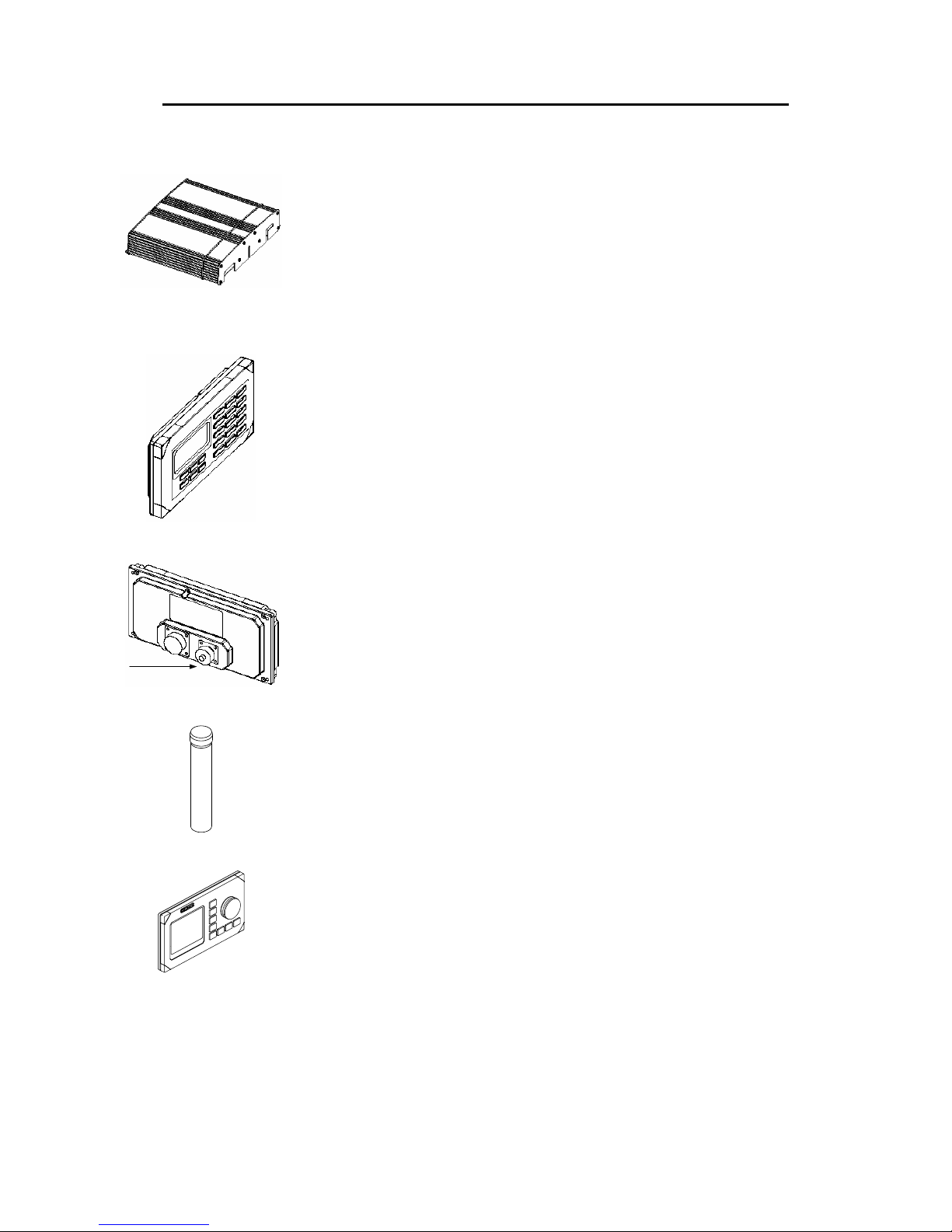
1.2 System components
An AI80 system includes the following units:
• AI80 Class A Mobile Unit
• GPS Antenna (GPS4)
• AI80 Minimum Keyboard and Display, 21-button with Pilot Port
Simrad AI80 MKD
(A101-12_1)
GPS antenna
(A101-01)
Interconnection cable
(A101-03)
Mounting kit
GPS antenna
(A101-02)
Class A Mobile Station
(A101-11_1)
Adapter cable
(A100-93)
Simrad
Interface cable to MKD
(A101-13_1)
Page 15
System overview
Man_user_AI80_r2 5
The Mobile Unit broadcasts the vessel’s position, speed and course
as well as static and voyage related information.
The unit incorporates two VHF receivers, one VHF transmitter, one
DSC receiver, one GPS receiver and a processor. The internal GPS
receiver is used for time synchronisation and for back-up position
sensor.
The MKD unit provides a simple user interface to the Mobile Unit
with basic presentation of configuration data and position data in a
4x20 character display.
Buttons are used for selecting display pages, for input of data to the
system, and for writing text messages transmitted to other vessels or
shore based AIS stations.
A Pilot Plug is included in the AI80 system and is located at the rear
of the MKD. The plug enables the pilot to connect a Personal Pilot
Unit (PPU) to the AIS system.
The supplied L1 GPS antenna is delivered with a universal antenna
mounting kit and an adapter cable with N connectors for connection
to a customer supplied GPS antenna cable, e.g. RG-214.
The system may also be delivered with an optional, external MKD.
This MKD provides either a 25x15 character display or a graphical
view.
Note ! A customer supplied VHF antenna must be included in the AI80
system. A qualified antenna must cover marine band (156 MHz - 164
MHz), have omni-directional vertical polarization and provide 2 to 5
dB gain.
Page 16

Simrad AI80 User Manual
6 Man_user_AI80_r2
THIS PAGE INTENTIALLY LEFT
BLANK
Page 17
User interface
Man_user_AI80_r2 7
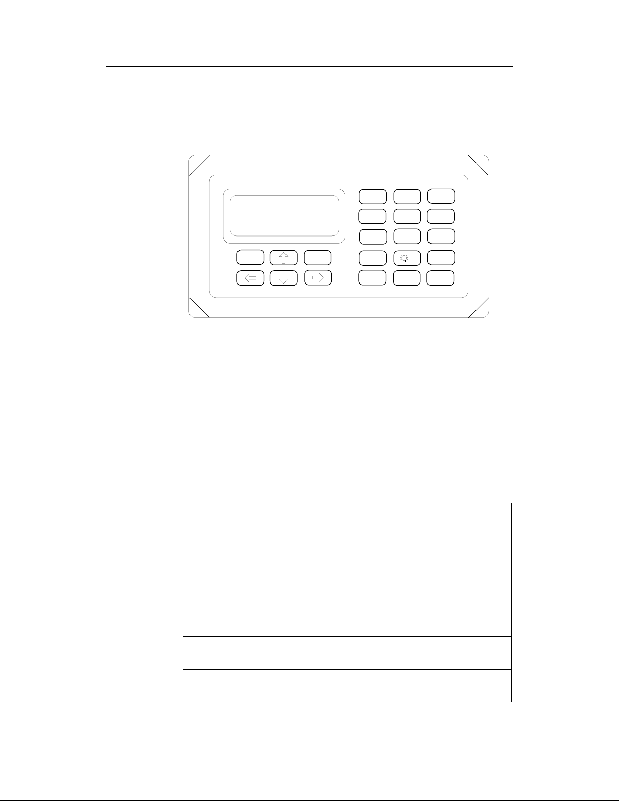
2 USER INTERFACE
2.1 AI80 user interface
OK
CANCEL
1 2
ABC
3
DEF
4
GHI
5
JKL
6
MNO
7
PQRS
8
TUV
9
WXYZ
VIEW
0
OFF
DELEDIT
INFO
SHIFT
AIS
SIMRAD
Display
4 x 20 character display with LED backlight.
Keypad
21-button keypad, alpha numeric and navigation keys.
LED indicators
The LED indicators on the front of the Mobile Unit can be used to
monitor status as well as data reception and transmission.
LED Colour Description
TX Off
Amber
Green
Red
Transmitter idle
Transmitting on AIS channel B
Transmitting on AIS channel A
Transmitter turned off
MSG Off
Amber
Green
No message/report being received
Message/report received on channel B
Message/report received on channel A
GPS Amber
Green
Indirect synchronisation free run
Internal GPS OK, GPS synch selected
ALM Off
Red
No alarm
Alarm - alarm relay activated
Page 18
Simrad AI80 User Manual
8 Man_user_AI80_r2
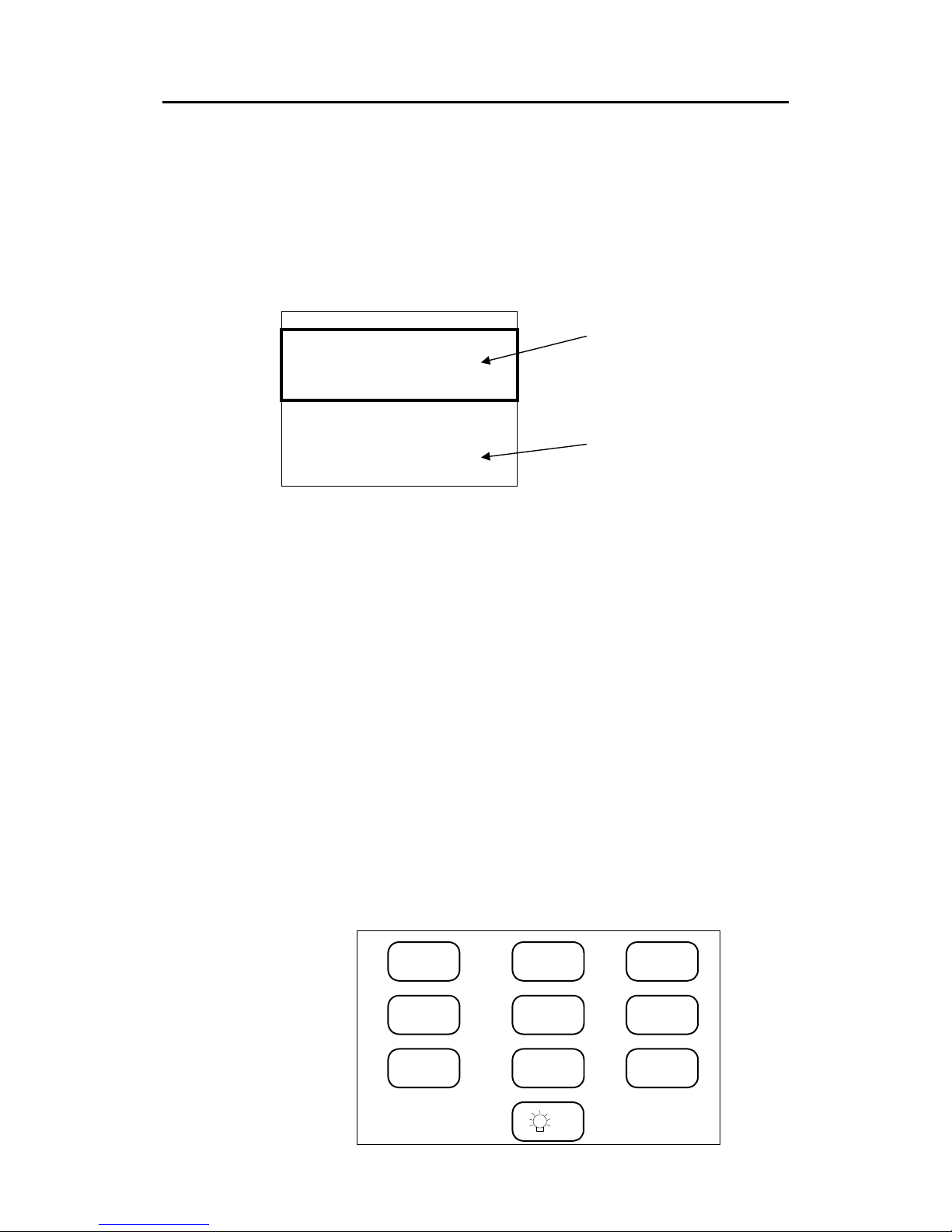
2.2 Buttons
Manoeuvring in the display: move the "viewport" up, down, left and
right using the ARROW buttons in order to display the text. A display
page is not limited to 4x20 characters. The manoeuvring allows the
user to move a "viewport" up/down and sideways in order to display
the entire text. This "window" of 4x20 characters used for viewing the
text, is called a viewport in this manual.
- Main Menu -----------Active alarms
Redundancy
Settings ▼
SMS
Downperiods
System
Entering data: by pressing the EDIT button when an editable
parameter is selected allows input of text, numbers and symbols. Enter
text by pressing the character buttons, enter numbers by first pressing
SHIFT followed by the selected number. Press SHIFT again to return
to character buttons. Enter SPACE and other non-alphabetic symbols
by using the Number 1 button in alpha numeric mode.
Selecting: by using the ARROW buttons the user can move the cursor
when the correct parameter has been selected. Press OK to view or
enter submenus.
Buttons are PRESSED to select the relevant functionality and HELD
to select alternative functionality when relevant. Some buttons have
toggle functionality that is triggered by repeatedly pressing this
button.
By pressing the buttons below the user can enter text or numbers.
Switch between characters and numbers by pressing the
SHIFT button.
SPACE and non-alphabetic symbols can be entered by using the
Number 1 button. When not in Edit mode, the Number 0 button
toggles the backlight on/off.
1
2
ABC
3
DEF
4
GHI
5
JKL
6
MNO
7
PQRS
8
TUV
9
WXYZ
0
OFF
Viewport
Display page
Page 19

User interface
Man_user_AI80_r2 9
VIEW
Press this button to enter the Main menu, Diagnostics menu and main
Ship List view.
INFO
Press this button to access the help system.
SHIFT
Press this button to toggle between numeric and alphabetic layout on
the keyboard while in Edit mode.
DEL
When entering text or numbers, pressing this button deletes the
characters to the left of the cursor. When entering text or numbers,
holding this button deletes all characters to the left of the cursor.
EDIT
By pressing this button the user can edit the selected parameter.
CANCEL
When entering text or numbers, pressing this button cancels the
editing. The entered value is discarded.
When interactive messages or requests are displayed, pressing this
button answers the equivalent to No (if applicable), and exits the
interactive message screen, returning to the viewport to the previous
position and content.
OK
Press this button to accept changes or selected parameters.
When predefined choices are displayed, pressing this button commits
the selected choice to the system. When any kind of interactive
message or request is displayed, pressing this button answers the
equivalent to Yes (if applicable), and exits the interactive message
screen, returning the viewport to the previous position and content.
Press the buttons below to move the viewport/cursor left, right, up,
down (i.e. scroll the lines in the display respectively).
Page 20
Simrad AI80 User Manual
10 Man_user_AI80_r2
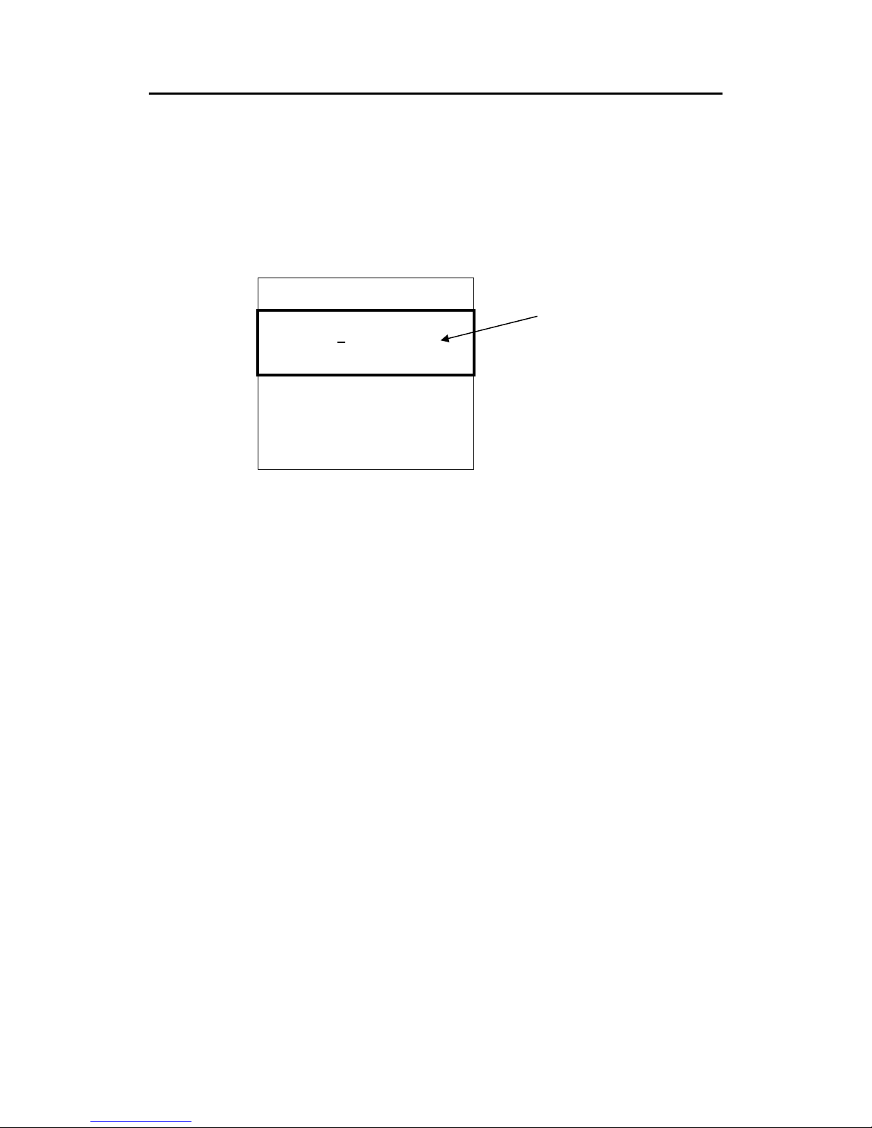
2.3 Using display and keypad
Manoeuvring and selecting
The uppermost line on the viewport is the page title. Select wanted
line with the UP/DOWN ARROW buttons. The selected line is marked
with an underscore character on the right side of the line content.
- Settings ------------Nav.Status
Voyage related
Gyro calibration ▼
Static data
VHF
LR
Serial
PIN
▲ ▼ symbols indicate that a page has more than three lines of
content. Manoeuvre the viewport up and down with the ARROW
buttons.
◄ ► symbols indicate that the page contains lines with more than 20
characters. Manoeuvre the viewport left and right with the LEFT and
RIGHT ARROW buttons respectively.
Select a highlighted item by pressing the OK button.
Dialogue boxes
Dialogue boxes inform the user about events or state changes that
require user interaction. Such events are:
• Alarms
• SMS
• Enter PIN
• Edit error
• Item Help
Dialogue boxes are shown as whole pages, i.e. they are displayed in
the whole "viewport", and forces the user to press one or more buttons
to continue. The dialogue box indicates the keys required to exit the
dialogue box. This is indicated by the button name encapsulated in
square brackets.
The bold lined rectangle
illustrates what is shown on
the screen.
Page 21
User interface
Man_user_AI80_r2 11
To facilitate recognition, the uppermost line on a dialogue box is
composed of a start pattern of three * signs, and a post fixed pattern of
* until the end of the line. A dialogue box prompting for PIN code
appears like the figure below.
*** PIN Code ***********
*B
[Cancel] [OK]
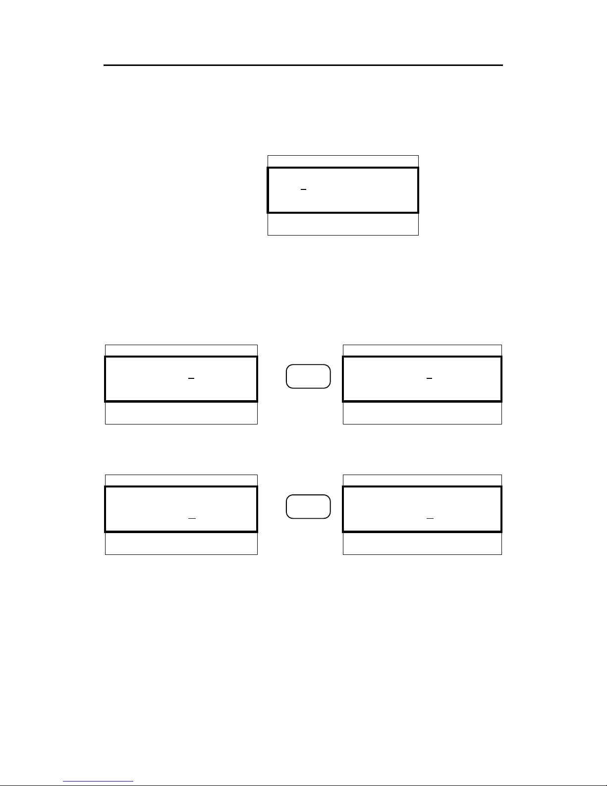
Editing
The user can edit a variable by pressing EDIT when highlighted. The
value of the current variable is stored and the user can start editing the
data. The user selects characters by repeatedly pressing numeric
buttons,
- Static data ---------- - Static data ---------MMSI: 000000001 MMSI: 000000002
Pos Source: Internal Pos Source: Internal
SurveyedLat: 00°00'▼
1 x
2
ABC
SurveyedLat: 00°00'▼
or, in cases were there are predefined variables, chooses from a list of
these by using the UP or DOWN ARROW buttons.
- Serial -------------- - SETTINGS ------------Sensor 1: 4800 Sensor 1: 4800
RTCM : 9600! RTCM : 4800!
PI : 38400 ▼
1 x
2
ABC
PI : 38400 ▼
The button between the displays indicates that pressing this button
when in the screen to the left, will result in the changes seen in the
screen to the right.
After editing, press OK to confirm changes and exit Edit mode, or
press CANCEL to discard changes. If the input exceeds the horizontal
length of the display (20 chars), it automatically scrolls. When editing
is completed and OK is pressed, it scrolls back. Values are saved by
holding the OK button pressed.
Page 22

Simrad AI80 User Manual
12 Man_user_AI80_r2
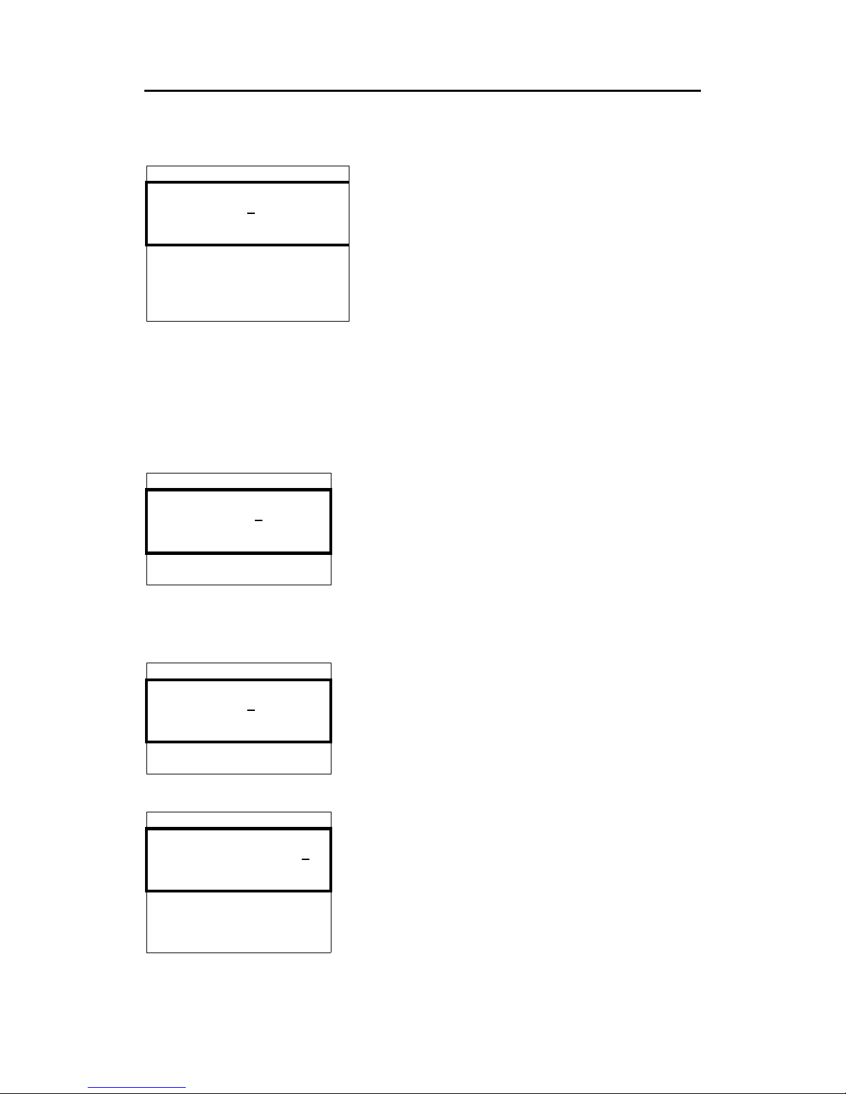
Information
The Info functionality provides the user with information about the
highlighted menu. A dialogue box with help text is provided if such a
text is existent for the menu. If not, a default text is displayed. A user
help dialogue box may look like this:
*** User Help ******
Persons on board,
Crew and passengers
included
[OK]
2.4 AI80 display pages and submenus
The table below shows the menu hierarchy. The ARROW buttons, OK
and CANCEL buttons are used to navigate in the menu tree.
Navigation between Ship List, Main Menu and Diagnostics is done
by pressing the VIEW button. This chapter describes all the menu
pages in the system.
Note ! If optional MKD is connected to the AI80, the menus for optional
MKD will also apply to the AI80.
Page 23

User interface
Man_user_AI80_r2 13
SHIP LIST
MAIN MENU
Alarms and LR
- Active Alarms
- LR Requests
Dynamic Data
Settings
- Nav.Status
- Voyage Related
- Gyro Calibration
- Static Data
- VHF
- LR
- Serial
- PIN
SMS
- Inbox
- Write Message
- Outbox
- Predefined
- Write Predefined
Downperiods
Chn.Management
- View Regions
- Add Region
- Edit Current Region
System
- Software Version
- System Control
- Restart GPS
- Software Upgrade
- MAC Address
DIAGNOSTICS
VHF
Serial
Config File
Page 24

Simrad AI80 User Manual
14 Man_user_AI80_r2
Ship list view
00.12 023 PRINSESS OF THE SEA
RANGE BRG NAME
01.11 025 FOSNINGEN▲
02.10 160 NORDLYS
02.22 343 SKIPPER V▼RSE
03.21 299 KONG SVERRE
06.44 164 BS:25791239
06.55 279 ATN:MUNKHOLMEN
07.00 234 SAR:123456789
The default main page of the system is
called Ship list view and contains
information about nearby vessels. Range,
Bearing and Name (MMSI if name not
available) are shown.
BS: in front of the MMSI indicates an AIS
base station.
ATN: in front of the ship name indicates an
Aids To Navigation target.
SAR: in front of an MMSI number indicates
a SAR aircraft.
Name: VANNINA
MMSI: 136547932
CallSign: CA122
LAT: 063°36'31.44N
LON: 010º24'13.73E
NavStatus: Under way using en
Dest: Lia
ETA: 2231100
- SHIP DATA ---------------Draught: 5.00 m
EPFD: GPS
ACC: LOW ▼
RAIM: off
Time: 11:54:27
COG: 170.00º
SOG: 010.00 kn
HDG: N/A
ROT: N/A
OnBoard: 12
IMO: 123
Type: 2
Keel: 10
LengthA: 12
LengthB: 2
LengthC: 12
LengthD: 2
DTE: Connected
If the operator presses OK for the selected
ship, a page displaying all information
about that ship appears. The figure shows
this page scrolled down. Press CANCEL to
return to Ship List View. If the ship name
cannot fit in the available space, press OK
to view the name in the Ship data page.
Horizontal scrolling is not available for the
Ship List View. This is a read only page.
The line indicator (underscore character) is
present none the less to facilitate the Info
function if the user presses
INFO. Pressing
EDIT has no effect on read only pages.
Page 25
User interface
Man_user_AI80_r2 15
Main menu
- MAIN MENU -----------Alarms and LR
Dynamic data
Settings ▼
SMS
Downperiods
Chn.Management
System
Press VIEW to enter the Main menu. The user can
select between Alarms and LR, Dynamic data,
Settings, SMS, Downperiods, Chn.Management
or System. Select menu with UP and DOWN
ARROW
buttons and enter the menu with OK.
Alarms and LR
Alarms and LR involves two different modes:
• New Alarm/LR received
• List of Alarms and List of LR
*** Alarm ***********
Tx Malfunction
[OK] to ack
New alarm
When a new alarm is received, a dialogue box will
appear. Press OK to acknowledge the alarm. If the
alarm condition disappears before it is acknowledged,
the dialogue page and the viewport is relocated to the
previous page and line.
As long as an alarm is active, it can be viewed by
navigating to the Active alarms page.
- Alarms & LR ------Active alarms
LR requests
Active alarm
All active alarms can be viewed under the Alarms
and LR menu by selecting them and pressing
OK.
- Active alarms ----Tx malfunction 11:00
VSWR exceeds 10:49
RX Chn1 malf. 10:3▼
RX Chn2 malf. 09:01
Heading Lost 08:33
No ROT info 03:42
Active alarms are listed with the latest alarm on top.
This is a read only page.
Page 26

Simrad AI80 User Manual
16 Man_user_AI80_r2
*** LR Req
123456789:ABCEFIOPUW
[OK] to send
[Cancel] to deny
New LR
When an LR request arrives, a dialogue box prompts
the user to send or deny the requested information.
The dialogue box provides information about
requester's MMSI and the codes for requested
information (e.g. C means Position). The Info
functionality can describe this upon request. If the
user does not respond within the given timeout, the
information is denied to the requester. All LR requests
are also stored in LR history. Press OK to send the
information or CANCEL to reject the information.
123456789:ab
- LR requests ------111111111: abcef ▲
222222222: ABCEFIOPUW
333333333: a ▼
444444444: ce
555555555: abc
666666666: ABCE
777777777: puw
LR requests
LR requests contains history of the last 30 requests.
This is also a read only page. The figure shows a list
with eight requests. First the MMSI of the requestor
followed by the information requested. If the
requested information is displayed with small letters,
the information is provided, otherwise denied.
Dynamic data
- Dynamic Data -----LAT: 063°36'31.44N
LON: 010°24'13.73E
COG: 000.00° ▼
SOG: 000.00kn
HDG: N/A
ROT: N/A
EPFD: GPS
The Dynamic Data page shows sensor readings. This
is a read only page. Press
CANCEL to return to Main
Menu.
Page 27

User interface
Man_user_AI80_r2 17
Settings
- Settings ---------Nav.Status
Voyage related
Gyro calibration
Static data ▼
VHF
LR
Serial
PIN
From the Main Menu, select Settings, press OK and
the Settings page appears.
All parameters that can be edited are found here. The
INFO button provides the user with additional
information about each menu item.
In the Settings main menu the user can choose
between Nav.Status, Voyage related, Gyro
calibration, Static data, VHF, LR, Serial or PIN.
Editing parameters in these pages is always protected
with a PIN-code.
To save edited parameters, press the OK button.
- Nav.Status -------NavStatus: MOORED
Nav.Status
In this page the user can set the appropriate navigation
status. Choose from predefined list.
- Voyage related ---Dest: Not defined
ETA: 24100730
OnBrd: 71 ▼
Draught: Not defined
Type: 123
Voyage related
All voyage related settings can be viewed and altered
in this page.
- Gyro calibration -►
Corrected heading: 9°
Gyro calibration
If a stepper or syncro gyro is used for heading input,
the heading can be calibrated here. This is done by
entering the actual heading. Ensure constant heading
when entering correction.
Page 28

Simrad AI80 User Manual
18 Man_user_AI80_r2
- Static data ------Name: VANNINA
Call: CA122
MMSI: 136547932
IMO: 3334445
Keel: 30.5
DimA: 0
DimB: 0
DimC: 0
DimD: 0
LocDimA: 0
LocDimB: 0
LocDimC: 0
LocDimD: 0
Static data
All static ship data can be viewed and altered here.
If MMSI number is changed, the unit should be
restarted, see chapter 4.3.
- VHF --------------TX: On
VDL: Off
Hold [OK] to save
VHF
In this page the transmission (TX) can be turned
ON/OFF, and also the VDL answer mode can be set.
- LR ---------------LR Mode: MANUAL
Hold [OK] to save
LR
In this page the LR mode can be set. Choose between
Manual and Automatic.
- Serial -----------Sensor 1: 4800
Sensor 2: 4800
Sensor 3: 4800 ▼
RTCM : 4800
PI : 38400
Pilot : 38400
LR : 4800
Serial
In this page the baud rate for the serial ports can be
set.
- PIN ---------------
PIN: ****
Hold [OK] to save
PIN
In this page the PIN code can be changed.
Page 29

User interface
Man_user_AI80_r2 19
SMS
- SMS --------------Inbox
Write Message
Outbox ▼
Predefined
Write Predefined
In the SMS main menu the user can choose between
Inbox, Write Message, Outbox, Predefined or
Write Predefined.
Select with UP/DOWN ARROW buttons and enter
page with OK.
- Inbox ------------122121211 29.Dec 12:39
Rasken 28.Dec 12:39
√ Tuppa 27.Dec 1▼:39
√ Bella 27.Dec 12:39
√ Joey 27.Dec 12:39
√ Elli 27.Dec 12:39
√ Barbie 27.Dec 12:39
Inbox
Inbox contains received messages (max 30) with
the most recent message at the top.
* Message *********
This message is an
inbox message
[DEL] to delete ▼
[OK] for next msg
[CANCEL] to close
[EDIT] to reply
Press UP/DOWN ARROW to select message. OK
displays the message to the user. If the message is
previously read, a check-sign is shown in front of that
line.
If the message is more than four lines, UP and DOWN
are used to scroll lines. Press DEL to delete the
message. Press OK to see next message without
deleting. Pressing CANCEL takes the user back to the
Inbox without deleting the message.
- Write message ----Channel: Default
Type: Addressed
Send to:----------- ▼
Predef.: NONE
Message:
Hold [OK] to send
Write message
Select Write message in the SMS menu to write a
message and the following screen appears.
Page 30

Simrad AI80 User Manual
20 Man_user_AI80_r2
Channel: Default
Type: Addr SR
Send to: 257999429
Predef.: NONE
Message: This message
is sent to the vessel
- Write message ----chosen when press
ing enter ▲
Hold [OK] to send
Select channel (A, B, Both, Default), type of message
to send (Addressed, Addressed Safety related,
Broadcast Safety related) and receiver (from list of
available stations). In addition the user can choose a
predefined message to appear. When all data are
entered, press OK to send message as configured.
- Outbox ------------122121211 29.Dec 12:39
√ Rasken 28.Dec 12:39
√ Tuppa 27.Dec 1▼:39
√ Bella 27.Dec 12:39
√ Joey 27.Dec 12:39
√ Elli 27.Dec 12:39
√ Barbie 27.Dec 12:39
Outbox
Outbox contains all sent messages. If the receiver
acknowledged the message, a check-sign is shown
in front of that line. The latest message is on top. If
the user wants to re-send or read a message, select
message with UP/DOWN and press OK. The page
shown in the figure is displayed.
- Message -----------This message is an
outbox message
[DEL] to delete ▼
[OK] for next msg
[CANCEL] to close
[EDIT] to resend
Selecting EDIT resends the message with the same
parameters as last time.
- Predefined --------Happy Day
Happy Easter
Merry Christmas ▼
Happy New Year
Happy Holiday
Predefined messages
In this page the user can edit, view or delete a
previously defined message. Press
OK to view or
edit a message, press DEL to delete a message.
Reading a predefined message has the same
functionality as reading a message in Inbox, except
that EDIT allows the user to edit the predefined
message.
Page 31

User interface
Man_user_AI80_r2 21
- Write predef. ------Name:
Message:
Hold [OK] to save
Write predefined
In the Write predefined page only the required data
are available for entry, e.g. the name of the
predefined message and the message text.
*** NEW SMS ***********
4 unread messages
[OK] go to Inbox
[CANCEL] later
New SMS received
When an SMS is received, the user is notified
through a dialogue box that appears on the screen.
Press
OK to read the message immediately or LEFT
ARROW
to delete the dialogue box. The message
can be found in Inbox.
Downperiods
- Downperiods ---- ►
23.May 08:00 - 23.May 08:30
23.May 09:00 - 23.May 09:30
23.May 10:00 - 23.M▼y 10:30
23.May 11:00 - 23.May 11:30
23.May 12:00 - 23.May 12:30
This page shows the last ten downtimes (start
and stop) for the Base Station on the format
DD/MM hh:mm - DD/MM hh:mm. It is a read
only page. Press CANCEL to return to Main
Menu.
Channel Management
- Chn.Mngt --------View Regions
Add Region
Edit Current region
In the Chn. management menu the user can choose
between editing current region, viewing all regions or
adding a new region.
- Regions ----------REGION 1
REGION 2
REGION 3 ▼
REGION 4
View regions
In this page all regions (max 8) are shown. This is a
read only page. Use UP/DOWN ARROW to select the
region of interest. The figure shows a list with three
regions.
Page 32

Simrad AI80 User Manual
22 Man_user_AI80_r2
- Region 2 ---------ChnA: 2087
ChnB: 2088
RxTx: TxA/TxB, RxA/Rx▼
TxPower: LOW
LAT NE: 64°00'00.00N
LON NE: 011°00'00.00E
LAT SW: 00°00'00.00N
LON SW: 000°00'00.00E
BW A: Default
BW B: Default
Zone: 0
Hold [OK] to save
Region
In this page the selected region is displayed. This
page is read only and shows each region's
parameters.
- Add region --------ChnA: 0
ChnB: 0
RxTx: TxA/TxB, RxA/Rx▼
TxPower: LOW
LAT NE: 00°00'00.00N
LON NE: 000°00'00.00E
LAT SW: 00°00'00.00N
LON SW: 000°00'00.00E
BW A: Default
BW B: Default
Zone: 0
Hold [OK] to save
Add region
In this page the user can add a region manually.
Refer chapter 3.6.
- Default Values ---ChnA: 0
ChnB: 0
TxPower: HIGH ▼
BW A: Default
BW B: Default
Hold [OK] to save
Edit Current region
In this page the user can edit current region settings.
Select parameter with
UP/DOWN, press EDIT to start
editing and
OK when finished. Hold OK button to save
changes to region. If the user presses
CANCEL, he is
informed that cancelling will delete his entered region.
If the region entered is not a valid region, the user is
notified about this through a dialogue box.
Page 33

User interface
Man_user_AI80_r2 23
System
- System -----------Software version
System control
Reset GPS ▼
Software Upgrade
MAC Address
From the System page the user can see the current
software version, restart the unit, reset the internal
GPS receiver, upgrade the software and view the
MAC Address.
- SW version---------Version: 4.00.00
This is a read only page for information purposes
only.
- System control-----Restart unit
If a system restart is required, select Restart unit and
press OK. The unit will now initiate the restarting
process.
- Restart GPS -------Restart GPS
If GPS tracking problems are experienced, restarting the
GPS may solve these problems.
- MAC Address -------MSB: 000.005.190
LSB: 000.005.200
In this page the MAC Address is viewed. This is a read
only page.
- Software Upgrade ---Start Upgrade
Hold [OK] to start
When pressing OK on this page, the configuration data
are stored for later retrieval. The unit enters an SW
upgrade mode where no other activities are performed
until power is cycled.
Page 34

Simrad AI80 User Manual
24 Man_user_AI80_r2
- Software Upgrade ---Backup Successful
Please turn off unit
and insert new CF card
If performing software upgrade, turn off power and
insert CF card with new software before power-on of
the unit. Upon power-on, the configuration data are
automatically retrieved. Thus enabling software
upgrade without loss of configuration data.
If software upgrade is initiated by accident, simply
cycle power, to restart the unit.
NOTE! Software Upgrade should only be performed by
qualified personnel.
Diagnostics
- DIAGNOSTICS -------VHF
Serial
Config file
The Diagnostics page shows the submenus
available to display, test and debug the
communication links and configuration settings.
- VHF ---------------Tx ChA: MSG01 00:01
Tx ChB: MSG03 00:20
Rx ChA: MSG04 00:03 ▼
Rx ChB: MSG17 00:02
Tx DSC: NONE
Rx DSC: NONE
VHF
The VHF page displays which messages have been
transmitted and received on the VDL interface.
This page will automatically be updated every
second.
- Serial -------------PI in : NONE 59:59
PI out : VDO 00:01
RTCM in : NONE 59:59 ▼
RTCM out: NONE 59:59
Sens1 in: NONE 59:59
Serial
Diagnostics of serial interfaces, type of sentence
and time elapsed since last transmission/reception
on each port.
- Config File -------- ►
!***********************
!*
!* Seatex AISBS▼
Config.File
Read-out of config. file. For service purposes
only.
Page 35

User interface
Man_user_AI80_r2 25
Pin code protection
The functionality in the mobile unit is protected by a PIN code. If the
user wants to edit a protected variable, e.g. Tx On/Off, he is presented
with a dialogue box. The default pin code for AI80 is 1234.
*** PIN CODE ********
**
[Cancel] [OK]
Use numeric buttons to write PIN code, press OK to
confirm. If the PIN code is correct, the user can start
editing the variable. If incorrect code is entered, a
dialogue box prompting the user to retry, is presented.
*** Wrong PIN *******
[OK] to try again
[Cancel] to cancel
Press OK to retry or CANCEL to cancel.
2.5 Optional MKD unit
The MKD unit includes the following elements:
VIEW
ALR
SMS
MENU
BACK ENTER
SIMRAD AI70
Display
The display presents information pages and menus used for data input.
Refer Optional MKD - display pages and submenus, page 26.
Rotating knob
The rotating knob is used for highlighting the different menu items on
the display.
ROTATING
KNOB
INPUT
BUTTONS
DISPLAY
DISPLAY
PAGE
BUTTONS
Page 36

Simrad AI80 User Manual
26 Man_user_AI80_r2
Display page buttons
ALR
SMS
MENU
Used for activating the Alarm page, the SMS page and the Menu
page.
Refer Optional MKD - display pages and submenus, page 26
onwards.
Input buttons
ENTER
Used for entering a highlighted sub-menu selected by the rotating
knob, and for confirming a highlighted selection.
Used for paging to previous/next page in submenus where more than
one page are available.
Also used for moving one line up/down in the keyboard function
when data is entered.
BACK
Used to save new settings and return to previous display.
Refer Entering Data, page 28.
2.6 Optional MKD - display pages and
submenus
In addition to the default View page (refer page 29, three different
display pages with corresponding submenus may be activated on the
MKD display:
Menu page (P1). Refer page 29
SMS page (P2). Refer page 31
Alarm page (P3). Refer page 31
The display pages are identified with P1, P2 and P3 in the upper right
corner.
When a submenu is activated, this submenu will be identified with a
second digit corresponding to the selected submenu’s number in the
display page. If more sublevels are available, a third digit will be
added as shown in the example below.
Page 37

User interface
Man_user_AI80_r2 27
=== Static Data ====== P14
AIS Transceiver 2/3
--------------------------
....
If a page or a submenu contains more than one
page, current page number and number of pages
will be shown below the page identification (e.g.
2/3).
In addition, ▲ ▼ symbols will be added to the
lower part of the display.
If more than one page are available, the UP/DOWN buttons on the
MKD are used for paging through available pages.
=== SMS Menu ======== P2
1.Inbox
2.Outbox
3.Predefined
4.Write Msg
5.Write SR Msg
6.Write BrcSR Msg
7.Write Pred.Msg
8.Clear Message Box
=== Inbox ========== P211
SANDPIPER
------------------------PLEASE BE AWARE OF THE
SUNKEN VESSEL PIER II
IN THE STRAUME STRAIT.
=== Inbox =========== P21
Received Messages
SANDPIPER 28/05 2300
JON ARVID 28/05 2210
#Andreas 28/05 1030
*Victor 28/05 0700
Jenny 27.05 2230
Nordstjernen 27/05 2015
Hansemann 26/05 1430
Lofoten 26/05 1015
Nordnorge 26/05 0945
Page 38

Simrad AI80 User Manual
28 Man_user_AI80_r2
Displaying submenus
A highlighted selection in a page or a menu indicates that the selection
may be entered, either for displaying data or for entering parameter
values.
ENTER
Rotate the knob to move the highlight to the submenu that is to be
entered, and press the ENTER button to display the submenu.
Menus where no selections are highlighted are only used for
displaying information.
Entering Data
A submenu that is used for entering data will include a keyboard
function in the lower part of the display as shown on the figure.
=========================
ABCDEFGHIJKLMNO
PQRSTUVWXYZ1234
567890.,!\”@-
Use the rotating knob for moving the highlight to the selected
character, and enter the character by pressing the ENTER button. The
arrow buttons on the MKD may be used for jumping up/down a line in
the characters.
The last four keyboard symbols are used as follows:
567890.,!\”@-
Space
Clear all
Backspace
Confirm that the entry is completed
Note ! If the field where data is to be entered already has a value, the clear
all symbol must be selected before new data may be entered.
Continue entering characters until the entry is completed, and confirm
the complete entry by moving the highlight to the symbol and
pressing the ENTER button.
BACK
When all data are entered, the
BACK button is pressed to activate the
entry. The operator will be requested to accept or reject
entries/changes.
=== Save Changes ========
YES
NO
Page 39

User interface
Man_user_AI80_r2 29
ENTER
Use the rotating knob to accept or reject the entries, and press the
ENTER button to accept the selection and return to previous page.
View page
VIEW
The View page is the default page on the MKD. This page will be
displayed when the system is turned ON and the initialisation
sequence is completed. The page is also activated by pressing the
VIEW button.
The View page shows range, bearing and name of other vessels in
ascending order relative to own vessel position. The vessel name
could be either MMSI (Maritime Mobile Service Identity) number or
name.
A base station would be identified with an asterisk in front of the base
station’s name or MMSI number.
Depending on the number of other vessels within range, the number of
pages will change dynamically.
The lower part of the View page contains own vessel’s information. If
an alarm is active or a message unread, this is indicated as shown
below.
RANGE BRG NAME
-------------------------
00.12 123.1 ORION
00.12.123.1 ANDREAS
01.12 134.2 BERIT
------------------------LAT:063°26´31.20N
LON:010°24´13.78E ALARM
SOG:024 COG:156 SMS
When a vessel name is highlighted and the ENTER button pressed, the
display will show static, dynamic and voyage data for the selected
vessel.
Menu page
MENU
The Menu page is accessed by pressing the
MENU button.
The page gives access to 12 submenus, used for displaying
information and for entering data.
Software version is shown in the lower part of the display.
Page 40

Simrad AI80 User Manual
30 Man_user_AI80_r2
Entries in the submenus selected from Main menu may be protected
by a security code. Refer Security settings , page 61.
=== Main Menu ======== P1
1.Nav.Status
2.Long range
3.Voyage Data
4.Static Data
5.Dynamic Data
6.Chn.Management
7.VHF Link
8.Downperiods
9.Ports
a.Answer Mode
b.System
c.Security
-------------------------
The Menu page includes the following selections:
Menu item Function Ref. page
1.Nav.Status
Used for setting the navigational status. 41
2.Long range
Displays active and resolved Long Range
interrogation requests (Option).
59
3.Voyage Data
Used for entering information about the current
voyage.
41
4.Static Data
Used under installation for entering static
vessel data.
64
5.Dynamic Data
Displays current data for the vessel. The
information is obtained from sensors, and no
manual entries are possible.
-
6.Chn.Management
Used for configuring different radio channels
for different chart zones.
68
7.VHF Link
Used for displaying and changing current VHF
settings.
49
8.Downperiods
Displays periods where the AI80 system has
been out of operation.
-
9.Ports
Gives access to configuration settings for
external serial ports.
65
a.Answer Mode
Configures the polling operation for the AI80
system.
67
b.System
Used for displaying system information, and
for restarting the AI80 system.
60
c.Security
Used for configuring the security level for data
entries in the AI80 system.
61
Page 41

User interface
Man_user_AI80_r2 31
SMS page
SMS
In the SMS page the operator may select functions available in the
AI80 Short Message System.
=== SMS Menu ========= P2
1.Inbox
2.Outbox
3.Predefined
4.Write Msg
5.Write SR Msg
6.Write BrcSR Msg
7.Write Pred.Msg
8.Clear Message Box
Refer Using the AI80 message system, page 50.
Alarm page
ALR
The Alarm page displays active alarms in the system.
Active, not acknowledged alarms are displayed in capital letters,
while acknowledged alarms are displayed in lowercase. When an
alarm condition ceases, the alarm is removed from the list.
=== Alarms =========== P3
Own ship
------------------------CHANGED NAVST 1230
NO VALID ROT 1025
Utc lost 0845
Refer The alarm system, page 57.
Page 42

Simrad AI80 User Manual
32 Man_user_AI80_r2
THIS PAGE INTENTIALLY LEFT
BLANK
Page 43

Software setup procedure
Man_user_AI80_r2 33
3 SOFTWARE SETUP PROCEDURE
3.1 General
The AI80 system is set up with factory settings during testing. The
software setup must be performed as a part of the AI80 installation
procedure.
The software setup is performed from sub-menus available from the
Main Menu page, activated by pressing the VIEW button. The
respective Main Menu pages are shown below.
- MAIN MENU -----------Alarms and LR
Dynamic data
Settings ▼
SMS
Downperiods
Chn.Management
System
This is the Main Menu page for the AI80 with sub-
menus. All settings that need to be changed can be
found in the Settings sub-menu.
For manoeuvring in the menus and for entering
data, refer to AI80 user interface on page 7.
Note ! The software settings may be protected by a security code. When
entering parameters defined with a security level other than 0, the
access code has to be entered before these settings can be changed.
Refer Security settings AI80 in the next pages and page 61.
3.2 Security settings AI80
- Settings ---------Nav.Status
Voyage related
Gyro calibration
Static data
VHF ▲
LR
Serial
PIN
Security PIN code
All entries on this page are protected by a PIN code.
Initially, a default authorisation code is used for
altering data fields in the Settings page. The default
PIN code is: 1234. We recommend to change to a
vessel specific PIN code.
Enter new four digit PIN code by selecting PIN and
PIN: **** on the Settings menu.
Note! If the PIN code is lost, contact Customer
Support for help to retrieve the correct PIN code.
Page 44

Simrad AI80 User Manual
34 Man_user_AI80_r2
3.3 Entering static data
- Static data ------Name: VANNINA
Call: CA122
MMSI: 136547932
IMO: 3334445
Keel: 30.5
DimA: 0
DimB: 0
DimC: 0
DimD: 0
LocDimA: 0
LocDimB: 0
LocDimC: 0
LocDimD: 0
Static data are specific ship data that do not change
from one voyage to another. In order to input static
data, select parameters by pressing EDIT and press
SHIFT to access text mode.
If MMSI number changes, the unit should be restarted,
see the Simrad AI80 Installation Manual for details.
Name: The vessel name (text).
Call: The vessel call sign (text).
MMSI: The Maritime Mobile Signal Identifier
number.
IMO: The vessel IMO number.
Keel: Height over keel. Total height of vessel in
metres.
DimA: External GPS antenna location
DimB: External GPS antenna location
DimC: External GPS antenna location
DimD: External GPS antenna location
LocDimA: Internal GPS antenna location
LocDimB: Internal GPS antenna location
LocDimC: Internal GPS antenna location
LocDimD: Internal GPS antenna location
C
D
B
A
External GPS/GNSS antenna dimensions. Since the vessel's
primary GPS receiver is used as reference for the transmitted AIS
position, the physical location (horizontal plan only) of the vessel
GPS antenna should be input to the AIS in metres.
Setup by entering: DimA, DimB, DimC & DimD.
Internal GPS antenna dimensions. The AIS internal GPS receiver
is backup position sensor for the vessel primary GPS receiver. The
AIS internal GPS antenna's physical location (horizontal plane only)
also needs to be input to the AIS in metres.
Setup by entering: LocDimA, LocDimB, LocDimC & LocDimD.
Page 45

Software setup procedure
Man_user_AI80_r2 35
3.4 Configuring external serial ports
The serial port baud rate must be set up according to external
instrumentation. The sensor interfaces comply with the NMEA 0183,
version 3.0. Change the baud rates accordingly.
Enter the Serial page by selecting Settings in the Main Menu, and
Serial in the Settings menu. In the Serial page, press EDIT to start
editing the baud rate. Hold OK to save.
3.5 VHF data link
The VHF page includes ON/OFF status for transmitter and VDL
answer mode.
ON/OFF status: The transmitter setting is recommended set to TX:
ON.
Note ! The transmitter may be turned OFF at Master's discretion should an
emergency situation occur. However, the AIS receiver will still be
functioning and thus AIS data from other vessels will still be received.
VDL answer mode: VDL answer mode allows the configuration of
the AIS unit with regard to how it responds to inquiries by binary
messages (messages 6 and 8).
An inquiry of this type could be a request for information regarding
number of persons onboard, draught etc. If turned OFF, the AIS will
ignore the inquiry.
Note ! The VDL setting "ON" indicates that answer mode to interrogator is
enabled when message 6 or 8 containing interrogation functional
identification, is received.
3.6 Configuring radio channels
Viewing a region's settings
Under this option a list of all registered regions is displayed. By using
the ARROW buttons, regions can be individually selected. Selecting a
region is done by pressing the OK button and region parameters will
be shown. This is a read-only page.
Page 46

Simrad AI80 User Manual
36 Man_user_AI80_r2
Adding a region
- Add region --------ChnA: 0
ChnB: 0
RxTx: TxA/TxB, RxA/Rx▼
TxPower: LOW
LAT NE: 00°00'00.00N
LON NE: 000°00'00.00E
LAT SW: 00°00'00.00N
LON SW: 000°00'00.00E
BW A: Default
BW B: Default
Zone: 0
Hold [OK] to save
To edit these parameters, use the ARROW buttons to
manoeuvre to the parameter of interest and press
EDIT. Use the DEL button if necessary, and enter the
new value. If non-digits are required, press the
SHIFT button to change to alpha mode. Press the
SHIFT button again to return to digit mode.
While in alpha mode, letters and special characters
can be entered (e.g. the degree symbol °).
Note ! If the user tries to enter a region which parameters locates the region
more than 500 nautical miles away from the vessel, the region will
automatically be discarded. Also when the vessel position is further
than 500 nautical miles from the region, this region is automatically
discarded by the AIS unit.
ChA: The radio channel to be used as channel A.
ChB: The radio channel to be used as channel B.
RxTx: Transmission/reception mode. This parameter indicates
whether or not the AIS should transmit and receive on both channels,
or on only a subset of these.
TxPower: The transmission power of the radio. Low equals 2W, and
High equals 12W.
Lat/Lon: The rectangular area to which the radio parameters apply.
The area is specified by entering the coordinates for the north-east
corner and the south-west corner.
BW A: Bandwidth for the selected channel A.
BW B: Bandwidth for the selected channel B.
Zone: Transition zone for the region. This parameter is given in
nautical miles, and provides information about the transition zone of
the region in which the AIS should change radio parameters to the
ones specified for the region.
Page 47

Software setup procedure
Man_user_AI80_r2 37
Edit current region
This function is used to change the current radio parameters and is
similar to Add Region, the only difference being that by changing
these values the default parameters for the current region are altered
and take effect immediately.
Note ! For software setup procedure using optional MKD see Appendix B -
Software setup using optional MKD, page 61 .
Page 48

Simrad AI80 User Manual
38 Man_user_AI80_r2
THIS PAGE INTENTIALLY LEFT
BLANK
Page 49

Operation
Man_user_AI80_r2 39
4 OPERATION
4.1 General
The AI80, once activated, will continuously and autonomously
broadcast the vessel’s position and all the static and dynamic
information as required by IMO.
However, while the vessel’s speed and rate of turn manoeuvres will
automatically determine the update rate, there remains a need for the
Master or an authorized person to manually input, at the start of the
voyage and whenever changes occur, the following voyage related
data:
• ship’s draught
• type of hazardous cargo (most significant hazard carried)
• destination and ETA (at master’s discretion)
• the correct and actual navigational status
• safety related short messages, when appropriate
Refer Changing parameters during operation, page 41 onwards.
Caution! The Officer on Watch (OOW) should always be aware that
other ships and, in particular, leisure craft, fishing boats and
warships, and some coastal shore stations including Vessel
Traffic Service (VTS) centres, might not be fitted with AIS. The
OOW should also be aware that AIS fitted on other ships as a
mandatory carriage requirement, might, under certain
circumstances, be switched off on the Master’s professional
judgment.
An AIS system should always be in operation. It is recommended that
the AIS is not switched off during port stays because of the value of
the ship information to port authorities.
Whether at sea or in port, if the Master believes that the continued
operation of AIS might compromise the ship’s safety or security, the
VHF transmitting may be switched off as described in Turning the
VHF transmitter OFF, page 41. This might be the case in sea areas
where pirates and armed robbers are known to operate.
However, the VHF transmitting should be re-activated as soon as the
source of danger has disappeared.
Page 50

Simrad AI80 User Manual
40 Man_user_AI80_r2
It may be necessary to switch off AIS or to reduce the transmission
power during some cargo handling operations. Actions of this nature
should always be recorded in the ship’s logbook.
4.2 Turning the AI80 system ON
The system is turned ON when power is connected to the AI80. After
a two-minute initialisation period the unit will have full functionality.
No ON/OFF switch is included on the unit. The system is turned OFF
when power is disconnected.
4.3 Restarting the AI80 system
The AI80 Mobile Unit may be restarted by using the following
procedure:
- System control-----Restart unit
1. Press the VIEW button to activate the Main menu,
and select System. The System menu will be
displayed.
2. Select System Control, and Restart Unit will be
highlighted.
3. Press the OK button to restart the Mobile Unit.
After a two-minute initialisation period the unit
will have full functionality.
4.4 Adjusting brightness and contrast
AI80 display settings
SHIFT
0
OFF
Press SHIFT and 0 buttons simultaneously to adjust brightness and
contrast. Select Display contrast and the Display setting view
appears. Select wanted setting (Contrast or Backlight) by pressing
EDIT. Scroll selections with UP/DOWN ARROW. Press OK to
confirm change.
0
OFF
Press the Number 0 button to toggle the backlight ON/OFF.
Page 51

Operation
Man_user_AI80_r2 41
The front LEDs may be switched off from this menu.
- Display setting ---Contrast: LOW
Backlight: HIGH
LED: ON
4.5 Changing parameters during operation
Updated information about the navigational status and the current
voyage data should always be entered into the AI80 system.
If the Nav.Status or Voyage Data parameters are defined with a
security level other than 0, the access code has to be entered before
these settings can be changed. Refer Security settings AI80, pages 33
and 61.
Setting the Navigational Status
It is important to set the navigational status with regard to the current
vessel status as this affects the reporting rate and information
transmitted to other vessels.
For AI80 press the VIEW button to activate the Main Menu, select
Settings and Nav.Status. Press EDIT to activate the predefined list.
Select wanted status, hold OK to save.
Entering Voyage Data
For AI80 press VIEW to enter Main Menu, select Settings and
Voyage related. The Voyage related page will be displayed showing
previously set voyage navigational data. Hold
OK to save.
4.6 Turning the VHF transmitter OFF
In situations where transmission would endanger the ship, e.g. in war
situations, piracy etc, the VHF transmitter may be turned OFF.
For AI80 press VIEW button to activate Main Menu, select Settings
and VHF. Select TX, press EDIT and choose ON/OFF. Hold OK to
save.
Page 52

Simrad AI80 User Manual
42 Man_user_AI80_r2
4.7 Using the AI80 message system
The AI80 system includes an SMS function, making it possible to
send text message to other vessels or to shore based stations.
Using SMS in AI80
All SMS functions are selected from the SMS page, activated by
selecting SMS in the Main Menu.
New SMS received
*** NEW SMS *********
4 unread messages
[OK] go to Inbox
[CANCEL] later
When an SMS is received, the user is notified through
a dialogue box that appears on the screen. Press OK to
read the message immediately or LEFT ARROW to
delete the dialogue box. The message can be found in
the Inbox.
See page 19 onwards for more SMS dialogue boxes.
The Inbox
The user can enter the Inbox by pressing OK on the New SMS
received dialogue or by entering the SMS menu under Main Menu
and selecting Inbox.
Press UP/DOWN ARROW to select message. OK displays the message
to the user. If the message is previously read, a check-sign is shown in
front of that line.
If the message is more than four lines, UP and DOWN are used to
scroll lines. Press
DEL to delete the message. Press OK to see next
message without deleting. Pressing CANCEL takes the user back to
Inbox without deleting the message.
Write Message
Select Write Message in the SMS menu and press OK. This allows
the user to prepare a message for transmission to another vessel.
Select channel for transmission (A, B, Both, Default), type of message
to send (Addressed, Addressed Safety related, Broadcast Safety
related) and receiver (from list of available stations). In addition the
user can choose a predefined message to appear. If a predefined
message is not used, the user can enter a specific message after
Message. Enter a message by pressing EDIT and the cursor starts to
Page 53

Operation
Man_user_AI80_r2 43
blink. Enter text by pressing the character buttons, enter numbers by
first pressing SHIFT. Press SHIFT again to return to character
buttons. Enter SPACE and other non-alphabetic symbols by using the
Number 1 button. When all data are entered, press OK to send
message as configured.
Many AIS manufacturers do not implement the full set of AIS SMS
messages. The AI80 has a complete set of AIS SMS messages
including Addressed, Safety related addressed and Safety related
broadcast messages accessible from the display. Please note that
Addressed (addressed binary message 6) is often excluded by other
AIS manufacturers. Therefore it is recommended that the user uses
Safety related messages instead of Addressed.
The Outbox
Outbox contains all sent messages. If the receiving AIS unit
acknowledged the message, a check-sign is shown in front of that line.
The latest message is on top. If the user wants to re-send or read a
message, select a message with UP/DOWN and press OK.
Viewing and editing predefined messages
Select Predefined and press OK to enter the Predefined page. Here
the user can edit, view or delete a previously defined message. Press
OK to view, EDIT to change and DEL to delete a message. Reading a
predefined message has the same functionality as reading a message in
Inbox, except that EDIT allows the user to edit the predefined
message.
How to write a predefined message
Enter the Write Predefined page by selecting it and pressing OK.
Press
EDIT to write a new predefined message. Every predefined
message is identified by a name. Write this identifier under Name and
continue with the predefined message under Message. Enter text by
pressing the character buttons, enter numbers by first pressing
SHIFT.
Press SHIFT again to return to character buttons. Enter SPACE and
other non-alphabetic symbols by using the Number 1 button. When
the message is completed, hold OK to save.
4.8 The alarm system
The AI80 system does not include an internal acoustic alarm. It is,
however, possible to connect an external alarm to the system. See the
Simrad AI80 Installation Manual for details.
Page 54

Simrad AI80 User Manual
44 Man_user_AI80_r2
AI80 alarms
*** Alarm ***********
AIS: external EPFS
Lost
[OK] to ack
If an alarm situation occurs, the Alarm menu will
appear and display the latest alarm. This alarm will be
displayed until it is acknowledged by pressing the OK
button or the alarm condition ceases to exist. If further
alarms exist, they will be displayed in turn, starting
with the latest. As long as there are unacknowledged
alarms, the ALM LED will be red and the alarm relay
will engage, see the Simrad AI80 Installation Manual.
Displaying and acknowledging alarms
- Alarms & LR ------Active Alarms
LR requests
In the Main Menu there is an entry for Alarms &
LR. By selecting it, the user can select between
viewing active alarms and LR requests.
- Active Alarms
Ext.epfs lost √
Heading lost √
No valid rot √
By selecting the Active Alarms entry, the user can
view all active alarms registered in the AIS unit. A
check mark after the alarm indicates that the alarm has
been acknowledged.
Page 55

Operation
Man_user_AI80_r2 45
4.9 Long-Range messages (option)
The AI80 contains a long-range interface for connection to an external
communication system like Inmarsat. If long-range equipment is
included in the system, it is possible to poll AIS system data from
anywhere within the Inmarsat coverage area.
AI80 long-range
*** LR-inquiry ******
VTS: ABCEFIOPW
[OK] to send
[CANCEL] to reject
Upon a reception of an LR inquiry, the LR inquiry
menu appears. It contains the name of the inquirer and
the function request string. By pressing the OK button
the AIS unit responds to the inquiry and by pressing
CANCEL the AIS unit sends a rejection message to
the inquirer.
- Alarms & LR -----Active Alarms
LR requests
To view a list of all the long-range inquiries that have
been received, access the Main Menu and enter the
Alarms & LR option.
- LR Answers --------
√ VTS: ABCEFIOPW
√ HECTOR: ABC
√ VTS: ABCEF ▼
[Hold OK] Clear all
Under LR requests there is a complete list of all LR
requests (inquiries). The check mark before the name
of the inquirer indicates that the request has been
processed.
Deleting a long-range request
By holding the OK button pressed, the LR list will be cleared.
Page 56

Simrad AI80 User Manual
46 Man_user_AI80_r2
THIS PAGE INTENTIALLY LEFT
BLANK
Page 57

Appendix A - Operating procedure optional MKD
Man_user_AI80_r2 47
5 APPENDIX A - OPERATING
PROCEDURE OPTIONAL MKD
Optional MKD display settings
BACK ENTER
When the BACK and ENTER buttons are pressed simultaneously, the
AIS TERMINAL view will be displayed.
==> AISTERM 1.00.01 <==
SMS: : Brightness
MENU : Contrast
BACK : Exit
ENTER : Main - No
▼ : Debug - Off
BusResetCnt=1
Brightness:
Contrast:
SMS
Press the SMS button to activate the brightness settings, and adjust
the brightness by turning the rotating knob.
MENU
Contrast is adjusted by pressing the
MENU button, and then using the
rotating knob.
BACK
All changes are accepted and the display returned to the VIEW page
by pressing the
BACK button.
Note! The other functions in this display are not used.
Page 58

Simrad AI80 User Manual
48 Man_user_AI80_r2
Setting the navigational status
=== Main Menu ======== P1
1.Nav.Status
1. Press the MENU button to activate the
Main menu, select Nav.Status and press
the ENTER button. The Nav.Status page
will be displayed, showing previously
selected navigational status.
2. Repress the ENTER button to activate the predefined list.
=== Nav.Status ====== P11
Own Ship
------------------------ AT ANCHOR
=== Choose from list ====
UNDER WAY USING ENGINE
AT ANCHOR
NOT UNDER COMMAND
RESTR.MANOEUVRABILITY
CONSTRAINED BY DRAUGHT
M
O
O
RED
▼
Additional selections are available by pressing the arrow down
button.
Use the rotating knob to select the vessel’s current status, and
confirm the entry with the ENTER button. Activate the setting by
pressing the BACK button.
Entering voyage data
=== Main Menu ======== P1
3.Voyage Data
1. Press the MENU button to activate the
Main menu, select Voyage Data and
press the
ENTER button. The Voyage
Data page will be displayed, showing
previously set voyage navigational data.
Page 59

Appendix A - Operating procedure optional MKD
Man_user_AI80_r2 49
=== Voyage Data ===== P13
Own Ship
------------------------Dest :STAVANGER
ETA :05172245
Drght :120
OnBrd :15
Type : 123
The following information should be entered:
Dest: Voyage destination
ETA: Estimated time of arrival, entered as month, day, hour and
minutes (MMDDHHmm)
Drght: Vessel draught [1/10 m]
OnBrd: Total number of people on board
Type: Type of vessel. Refer Vessel Identifiers in the Simrad
AI80 Installation Manual.
Enter voyage data as described in Entering Data, page 28.
Activate the setting by pressing the
BACK button.
Turning the VHF transmitter OFF
=== Main Menu ======== P1
7.VHF Link
1. Press the MENU button to activate the
Main menu, select VHF Link and press
the ENTER button. The VHF Link page
will be displayed, showing current VHF
settings.
Page 60

Simrad AI80 User Manual
50 Man_user_AI80_r2
=== VHF Link ======== P17
AIS Transceiver
------------------------ChnA :2087
ChnB :2088
TxPower :High
BW A :Narrow
BW B :Default
Transmitter:TxOn
=== Choose from list ====
TxOn
2. Select Transmitter:TxOn, and press the
ENTER button.
In the lower part of the display it will
now be possible to select TxOff.
3. Confirm the selection by pressing the
ENTER button, and save the changes by
pressing the BACK button.
------------------------LAT:063°26´31.20N TXOFF
LON:010°24´13.78E ALARM
SOG:024 COG:156 SMS
When the VHF transmitter is turned OFF,
this will be indicated in the View page as
shown on the figure.
Using SMS in AI80 - optional MKD
SMS
All SMS functions are selected from the SMS page, activated by
pressing the SMS button.
=== SMS Menu ========= P2
1.Inbox
2.Outbox
3.Predefined
4.Write Msg
5.Write SR Msg
6.Write BrcSR Msg
7.Write Pred.Msg
8.Clear Message Box
Page 61

Appendix A - Operating procedure optional MKD
Man_user_AI80_r2 51
Receiving and reading an SMS message
------------------------LAT:063°26´31.20N TXOFF
LON:010°24´13.78E ALARM
SOG:024 COG:156 SMS
When an SMS message is received, this will
be indicated in the lower part of the View
page. When the message is opened, this
indication will be removed from the View
page.
To read the message, Press the SMS button to open the SMS page,
select Inbox and press the ENTER button.
The Inbox view will be displayed.
=== Inbox ============ P21
Received Messages
--------------------------
SANDPIPER 28/05 2300
Nordstjernen 28/05 2115
#Andreas 27/05 2010
Jenny 27/05 0945
*Lofoten 26/05 1030
The Inbox contains all messages received from other AIS systems,
both from base stations and from other Mobile Units. The latest
received message will be displayed on top of the list.
The following notations are used in the Inbox page:
• Unread messages: Vessel name with capital letters
• Security messages: *
• Broadcast messages: #
Page 62

Simrad AI80 User Manual
52 Man_user_AI80_r2
=== Inbox =========== P211
SANDPIPER
--------------------------
BE AWARE OF THE SUNKEN
VESSEL PIER II IN THE
STRAUME STRAIT.
The message is displayed by highlighting
the sender’s name and pressing the ENTER
button.
When the message text is displayed and the ENTER button repressed,
the following list of options appears:
=== Choose from list ===
-------------------------Delete
Reply
Reply SR
Reply BrCast SR
Delete: Delete the message
Reply: Reply as text message
Reply SR: Replay as safety related
text message
Reply BrCast SR: Reply as broadcast
related message
Writing and sending SMS messages
When writing a message in the AI80 system, the message can be
defined as:
• General text message
• Safety related message
• Broadcast message
In addition to this, predefined messages may be written and saved for
re-use.
Writing general text messages and safety
related messages
General and safety related text messages could be sent to any vessel
within reach, e.g. vessels presented in the View page.
A safety related message will be transmitted with higher priority than
a general text message, and will be transmitted before any other
pending general message.
1. Press the SMS button to activate the SMS menu, select Write
Msg for writing a general text message, or Write SR Msg for
Page 63

Appendix A - Operating procedure optional MKD
Man_user_AI80_r2 53
writing a safety related message. Confirm the selection by
pressing the ENTER button.
The Write Msg menu (P24) or Write SR Mgs (25) menu will be
displayed.
=== Write Msg ======= P24
Use Chn:
-------------------------
=== Choose from list ====
Default
A Only
B Only
Both
2. Select the channel that is to be used
when sending the message, and confirm
with the ENTER button.
The display will change to the Write
Msg menu:
=== Write Msg ======= P27
Use Chn:Default 151
-------------------------
=========================
ABCDEFGHIJKLMNO
PQRSTUVWXYZ1234
567890.,!\”@-
A text message may consist of up to
151 characters. As characters are
entered, the display will show
remaining number of characters that
may be entered.
3. Use the rotating knob and the ENTER
button to enter characters.
4. When the message is completed, the entry is confirmed by
moving the highlight to the symbol and pressing the ENTER
button.
The display will now show vessel and base station names that
may be selected as receiver for the message.
5. Use the rotating knob to highlight the receiver for the message,
and confirm with the
ENTER button to send the message.
All sent messages will be displayed in the Outbox view. Refer page
56.
Writing broadcast messages
Broadcast messages must be safety related, and they will be sent
without any specific destination. Text entry is similar to entering
general or safety related messages.
Page 64

Simrad AI80 User Manual
54 Man_user_AI80_r2
Any sent broadcast message will be displayed in the Outbox view
labelled with a # prefix.
Writing predefined messages
A predefined message may be defined and saved for re-use. When a
predefined message is to be sent, it may be defined as a general text
message, a safety related message or a broadcast message.
1. Press the SMS button to activate the SMS menu, select Write
Pred.Msg and press the ENTER button.
The Write Pred.Msg menu (P27) will be displayed:
=== Write Pred.Msg == P27
-------------------------
=========================
ABCDEFGHIJKLMNO
PQRSTUVWXYZ1234
2. Enter a name for the predefined
message, and confirmed the name by
moving the highlight to the
symbol
and pressing the ENTER button.
The display is now ready for entering
the predefined message text.
=== Write Pred.Msg == P27
DEPARTURE
------------------------ READY FOR DEPARTURE. ANY
FINAL ISSUES
=========================
ABCDEFGHIJKLMNO
PQRSTUVWXYZ1234
567890.,!\”@-
3. Use the rotating knob and the ENTER
button to enter characters.
When the message is completed, the entry is
confirmed by moving the highlight to the
symbol and pressing the ENTER button.
The display will now return to the Predefined Message view,
showing all predefined messages.
Sending a predefined message
When the Predefined Message view is active, one of the predefined
messages may be selected, eventually edited, and then sent.
Page 65

Appendix A - Operating procedure optional MKD
Man_user_AI80_r2 55
=== Predefined ====== P23
Predefined Messages
------------------------ DEPARTURE
SERVICE REQUEST
Select the message that is to be sent, and press the ENTER button.
=== Predefined Msg = P231
DEPARTURE
------------------------ READY FOR DEPARTURE. ANY
FINAL ISSUES
▲▼
The predefined message will be opened.
If more predefined messages are defined, it
is possible to scroll to previous/next
message by using the ▲▼ buttons.
When the correct message that is to be sent
is displayed, press the ENTER button.
The following selections will now be
available in the lower part of the display:
Edit Edit the current message before it is sent.
Send Send the message as a general text message to any
vessel in reach.
Send Sr Send the current message as a Safety related
message. Refer page 52.
Send BrCast Sr Send the current message as a Broadcast message.
Refer page 53.
Delete Delete the current message.
Page 66

Simrad AI80 User Manual
56 Man_user_AI80_r2
The Outbox
All sent messages will be automatically moved to the Outbox view.
As for the Inbox, the following notations are used in the Outbox
view:
• Messages not transmitted: Vessel name with capital letters
• Security messages: *
• Broadcast messages: #
=== Outbox ============ P2
Sent Messages
--------------------------
LITTLE JOHN 29/05 1230
nor cargo 29/05 1110
#broadcast 29/05 0915
*nordstjerna 28/05 2145
Before a general message or a safety related message is transmitted,
the AI80 system will automatically check that the selected vessel or
base station is able to receive the message. If not, the system will try
to resend the message three times. In this period the message will be
displayed with capital letters in the Outbox.
If a message is not accepted by the receiver, the message will remain
in the Outbox written with capital letters. The operator may then
resend the message manually by selecting the message, pressing the
ENTER button twice and then selecting Send again.
Page 67

Appendix A - Operating procedure optional MKD
Man_user_AI80_r2 57
Removing messages
The AI80 system may save up to 30 different messages. This includes
messages both in the Inbox and the Outbox, as well as predefined
messages.
To make sure that no messages are deleted unintentionally by the
system, the operator should regularly remove messages from the AI80
system manually.
The messages can be deleted one by one from the Inbox and the
Outbox as described in page 55, or from the SMS menu by selecting
Clear Message Box.
When Clear Message Box is selected, it will be possible to delete all
messages from the Inbox, the Outbox or all predefined messages.
=== SMS Menu ========= P2
1.Inbox
2.Outbox
3.Predefined
4.Write Msg
5.Write SR Msg
6.Write BrcSR Msg
7.Write Pred.Msg
8.Clear Message Box
=== Choose from list ====
Cancel
Clear Inbox
Clear Outbo
x
Optional MKD alarms
RANGE BRG NAME
-------------------------
00.12 123.1 ORION
00.12.123.1 ANDREAS
01.12 134.2 BERIT
------------------------LAT:063°26´31.20N
LON:010°24´13.78E ALARM
SOG:024 COG:156 SMS
If an alarm situation occurs, this will be
indicated in the lower right corner of the View
page.
The alarm indication will be active as long as the
alarm situation is present or until the alarm has
been acknowledged.
Page 68

Simrad AI80 User Manual
58 Man_user_AI80_r2
Displaying and acknowledging alarms
ALR
When an alarm situation has been indicated in the View page, the
alarm code may be displayed in the Alarms menu.
Press the ALR button to display the Alarms menu.
=== Alarms =========== P3
Own ship
------------------------CHANGED NAVST 1230
NO VALID ROT 1025
Utc lost 0845
In this menu, all present alarms will be listed
with the latest reported alarm on the first
line.
Active, not acknowledged alarms are
displayed in capital letters, while
acknowledged alarms are displayed in
lowercase.
When the alarm situation ceases, the alarm
will be removed from the list.
=== Alarms =========== P3
Own ship
------------------------CHANGED NAVST 1230
NO VALID ROT 1025
Utc lost 0845
=== Choose from list ====
Acknowl
ed
ge
An alarm is acknowledged by highlighting
the line, pressing the ENTER button and
then selecting Acknowledge or
Acknowledge All.
Page 69

Appendix A - Operating procedure optional MKD
Man_user_AI80_r2 59
Optional MKD long-range
=== Main Menu ======== P1
2.Long Range
The Long Range menu is displayed by
pressing the MENU button, selecting Long
Rang and then pressing the ENTER button.
=== Long Range ====== P12
Own ship
------------------------LR INFO REQ. 03.Jan 1230
lr info req. 01.Jan 2230
lr info req. 01.Jan 1145
In the Long Range menu, both active and
resolved long range requests will be listed
with the latest request first.
Active, not resolved request are displayed in
capital letters, while resolved requests are
displayed in lowercase.
This menu will also be displayed by
pressing the ALR button twice.
Resolving a long-range request
The AI80 Mobile Unit may be set up to answer a long range request
automatically or manually. Refer Answer mode , page 67.
If the system is set up to manually answer a long range request, the
request displayed in the Long Range menu should be highlighted and
the ENTER button pressed.
=== Request Info === P121
BELLA
------------------------Name, Callsign, IMO
Position, COG, SOG
=== Choose from list ====
Send
Deny
The Request Info page will be displayed,
showing the name of the requesting station.
The lower part of the display will show
actions to perform.
If Send is selected, a message containing
vessel information will be sent from the
AI80 system.
If Deny is selected, no respond will be given
to the request.
Independent of which action selected, the request will be displayed in
the Long Range menu. It will now be identified as a resolved
message written in lower case.
Page 70

Simrad AI80 User Manual
60 Man_user_AI80_r2
Deleting a long-range request
If a resolved request is selected in the Long Range menu and the
ENTER button pressed, the lower part of the display will give the
following options:
=== Provided Info == P121
BELLA
-------------------------
Name, Callsign, IMO
Position, COG, SOG
=== Choose from list ====
OK
Delete
Delete All LR
OK: Keeps the message and
exits the page
Delete: Deletes the active message
Delete All LR: Deletes all long-range
messages.
Restarting the AI80 system using optional
MKD
The AI80 Mobile Unit may be restarted by using the following
procedure:
=== Main Menu ======== P1
b.System
1. Press the MENU button to activate the Main
menu, and select System. The System menu
will be displayed.
=== System Menu ===== P1b
4.System Control
2. Select System Control in the System menu
(P1b). The Restart/Reset page (P1b4) will
be displayed, and Restart Unit will be
highlighted.
3. Press the ENTER button to restart the Mobile Unit. A short
initialization sequence will be started, indicated with stationary
amber light in the
TX, MSG, GPS and ALM LEDs on the Mobile
Unit.
Page 71

Appendix B - Software setup using optional MKD
Man_user_AI80_r2 61
6 APPENDIX B - SOFTWARE SETUP
USING OPTIONAL MKD
6.1 Security settings optional MKD
To avoid unauthorised input of data in the menus accessed from the
Main menu, the AI80 system should be set up with security codes and
different access levels.
3 different access levels may be defined:
Level 0: No security code required
Level 1: Access controlled by L1 PIN Code or L2 PIN Code
Level 2: Access controlled by L2 PIN Code
Access levels for the different menus are defined in the Security
submenu, activated from the Menu page.
Setting the security codes
When using the external, optional MKD the default security code
delivered with the Mobile Unit is “AIS” as for both Level 1 and Level
2. These security codes should be changed when the system is
configured for the first time. Use the following procedure to change
the security codes:
=== Main Menu ======== P1
c.Security
1. Press the MENU button to activate the Main
menu, and select Security. The Security
menu will be displayed.
=== Security ======== P1c
Authorisation
------------------------L1 PIN Code :********
L2 PIN Code :********
Nav.Status :1
Voyage Data :2
Static Data :0
Chn.Mgmt :0
VHF Link :1
Serial Ports :1
Netw.Settings :2
Answer Mode :0
Page 72

Simrad AI80 User Manual
62 Man_user_AI80_r2
2. Press ENTER when the L1 PIN Code line is highlighted. The
keyboard function will be displayed in the lower part of the
Security menu.
=== Security ======== P1c
Authorisation
------------------------L1 PIN Code :********
L2 PIN Code :********
Nav.Status :0
Voyage Data :0
Static Data :1
=========================
Enter authorisation code
PIN:
=========================
ABCDEFGHIJKLMNO
PQRSTUVWXYZ1234
3. Enter AIS (default security code), and
confirme the entry by moving the highlight to
the symbol and pressing the ENTER button.
4. Now enter the new security code for Level 1,
and confirmed the entry by moving the
highlight to the symbol and pressing the
ENTER button.
5. Highlight the L2 PIN Code and repeat the procedure above to
change the security code for Level 2.
6. Record the new codes and keep them in a safe location. If the new
codes are lost, a master code can be obtained from Customer
Support by supplying the MAC address, see page 65.
Changing the security levels
To avoid unauthorised input of data in the menus accessed from the
Main menu, the AI80 system should be set up with security codes and
different access levels.
Note ! All entries on the Security page are protected by L2 security code.
This code has to be entered before any parameters can be changed.
Refer item 3 below.
1. Activate the Security menu from the Main menu.
Page 73

Appendix B - Software setup using optional MKD
Man_user_AI80_r2 63
=== Security ======== P1c
Authorisation
------------------------L1 PIN Code :********
L2 PIN Code :********
Nav.Status :0
Voyage Data :0
Static Data :1
Chn.Mgmt :2
VHF Link :1
Serial Ports :1
Netw.Settings :2
Answer Mode :1
2. Highlight the parameter group for which the
security level is to be changed, and press the
ENTER button. The lower part of the display
will now show the keyboard function.
3. Enter the security code for Level 2, move the
highlight to the symbol and press the
ENTER button. In the lower part of the display
it will now be possible to change security level
for the selected parameter.
=========================
012
4. Select security level, and confirm by highlighting the symbol
and pressing the ENTER button.
5. Continue entering security levels for the remaining parameter
groups.
Note ! To ease the operation of the system, all parameters that have to be
changed during normal operation should be set to Level 0.
Note ! Once authenticated with L1 or L2 PIN code, the authentication is
valid until the View page has been displayed for 5 seconds. To protect
the AI80 security systems, the MKD returns to the View page when not
used for 15 minutes. In high security applications we recommend
manually returning to the View page when a change that required
authentication is completed.
Page 74
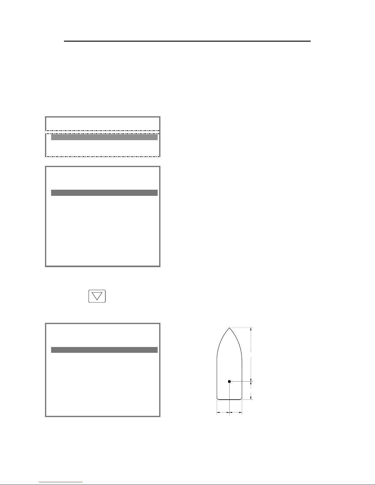
Simrad AI80 User Manual
64 Man_user_AI80_r2
6.2 Entering static data optional MKD
All vessel data that do not change from one voyage to another should
be entered during installation.
If MMSI number is changed, the unit should be restarted, see chapter
4.3.
=== Main Menu ======== P1
4.Static Data
1. Press the MENU button to activate the Main
menu, and select Static Data. The Static Data
menu will be displayed.
=== Static Data ===== P14
Own Ship 1/3
------------------------Name :ANNE BERIT
Call :TA164GH
MMSI :124395856
IMO :1098563
Keel :12
▼
The following information should be entered:
Name: Vessel name
Call: Vessel’s call signal
MMSI: The vessel’s Maritime Mobile Signal
Identifier number
IMO: Vessel’s IMO number
Keel: Vessel height over keel in metres. Total
height from keel to mast.
Use the arrow-down button to move to next page where horizontal
location for the GPS antenna included in the AI80 system should be
entered. Refer to the Simrad AI80 Installation Manual.
=== Static Data ===== P14
AIS Transceiver 2/3
------------------------Length A :30
Length B :10
Length C :7
Length D :7
C
D
B
A
Page 75

Appendix B - Software setup using optional MKD
Man_user_AI80_r2 65
Page 3 in the Static Data menu, entered by pressing the Arrow-down
button, is used for entering horizontal location for the vessel’s main
GPS antenna.
=== Static Data ===== P14
GNSS 3/3
------------------------Length A :20
Length B :20
Length C :9
Length D :5
▲
6.3 Configuration external serial ports
optional MKD
The baud rate for each serial port used for interfacing external
equipment has to be configured from the Serial ports submenu.
=== Main Menu ======== P1
9.Ports
1. Press the MENU button to activate the Main
menu, and select Ports.
=== Ports ============ P19
1.Serial Ports
2.MAC adr.
2. Select Serial Ports in the Ports menu. The
Serial Ports page will be displayed.
=== Serial Ports === P191
External Ports
------------------------PILOT :38400
PI :38400
LongeRange :4800
RTCM :4800
SENSOR-1 :4800
SENSOR-2 :4800
SENSOR-3 :4800
Page 76

Simrad AI80 User Manual
66 Man_user_AI80_r2
3. Highlight the port that is to be configured, and press the ENTER
button. The lower part of the display will now show baud rates
available for the selected port.
Refer Connecting and configuring external equipment in the Simrad
AI80 Installation Manual.
6.4 Port settings and MAC address optional
MKD
The Ports menu is used by the operator to change serial parameters
and view the MAC address.
=== Main Menu ======== P1
9.Ports
1. Press the MENU button to activate the
Main menu, and select Ports.
=== Ports =========== P19
1.Serial Ports
2.MAC adr.
2. Select MAC adr. in the Ports menu. The
MAC adr. page will be displayed.
=== MAC adr. ======= P192
External Ports
------------------------MAC MS :000.005.190
MAC LS :000.000.206
Page 77

Appendix B - Software setup using optional MKD
Man_user_AI80_r2 67
6.5 Answer mode optional MKD
The Answer mode page configures the polling operation for the AI80
system.
=== Main Menu ======== P1
a.Answer Mode
1. Press the MENU button to activate the Main
menu, and select Answer Mode.
=== Answer Mode ===== P1a
Current Settings
------------------------LongeRange :Automatic
VDL Response :On
The following parameters may be defined:
LongRange Configures the long-range polling. The following
selections are available:
Automatic: The AI80 system will automatically
reply to a long-range request. The
request will however be listed in the
Long Range view.
Manual: The operator will have to manually reply to a
request.
The long-range function is optional and requires
additional external equipment. Refer Long-Range
messages (option), page 45.
VDL Response Configures the normal VHF polling. Could be set
to ON (default) or OFF.
Note ! The VDL setting "ON" indicates that answer mode to interrogator is
enabled when message 6 or 8 containing interrogation functional
identification, is received.
Page 78

Simrad AI80 User Manual
68 Man_user_AI80_r2
6.6 Configuring radio channels optional MKD
AIS systems normally operate on two AIS channels: channel 2087 and
channel 2088. Where these channels are not available regionally, other
channels may be configured by using the Chn.Management
submenu. Maximum 8 regions may be configured.
=== Main Menu ======== P1
6.Chn.Management
Press the MENU button to activate the Main
menu, and select Chn.Management.
The Chn.Management submenu has three options for channel
management, described in the next pages.
=== Chn.Management == P16
1.Edit Cur.Reg.
2.View Regions
3.Add Region
Page 79

Appendix B - Software setup using optional MKD
Man_user_AI80_r2 69
Adding a region
=== Add Region ===== P163
REGION-1
------------------------ChnA :143
ChnB :144
RxTxMode:TxA/TxB/RxA/RxB
TxPower :High
LAT NE :000°00´00.00N
LON NE :000°00´00.00E
LAT SW :000°00´00.00N
LON SW :000°00´00.00E
BW A :Default
BW B :Default
Zone :2
The Add regions option is used for defining new
regions.
When regions are defined, the AI80 system will
automatically jump to the defined VHF channels
when the vessel enters this region.
The following parameters have to be defined:
ChnA/ChnB: VHF channels used for transmitting.
RxTxMode: Channels (A/B) used for transmitting/receiving
TxPower: Transmission power. Selectable options: High (12.5
W) and Low (2 W).
LAT NE: North-East latitude coordinates for the defined area.
LON NE: North-East longitudinal coordinates for the defined
area.
LAT SW: South-West latitude coordinates for the defined area.
LON NE: South-West longitudinal coordinates for the defined
area.
NE
SW
BW A/BW B: Bandwidth for the VHF channels used in this area.
Selectable options: Default (maximum bandwidth
allowed in this area) and Narrow (12,5 kHz).
Zone: The size of the transition area in nautical miles inside
the region.
Page 80

Simrad AI80 User Manual
70 Man_user_AI80_r2
Editing current region
=== Edit Cur.Reg == P161
REGION-1
-----------------------ChnA :143
ChnB :144
RxTxMode:TxA/TxB/RxA/RxB
TxPower :High
LAT NE :012°13´23.56N
LON NE :132°36´14.02E
LAT SW :034°56´21.06N
LON SW :125°56´12.21E
BW A :Default
BW B :Default
Zone :2
The Edit Cur.Reg. option enables the
operator to change parameters for the
current AIS channels.
Viewing a region’s settings
=== View Cur.Reg === P162
REGION-1 2/6
------------------------ChnA :143
ChnB :144
RxTxMode:TxA/TxB/RxA/RxB
TxPower :High
LAT NE :012°13´23.56N
LON NE :132°36´14.02E
LAT SW :034°56´21.06N
LON SW :125°56´12.21E
BW A :Default
BW B :Default
Zone :2 ▲▼
The View Regions option displays all
defined regions. This is a read only page and
no configuration changes can be made.
The view regions may consist of up to 8
pages, indicated in the upper left corner as
e.g. 2/6. The ▲ and▼-buttons are used for
displaying available regions.
Page 81

Appendix C - Type approval certificate
Man_user_AI80_r2 71
7 TYPE APPROVAL CERTIFICATE
Page 82

Simrad AI80 User Manual
72 Man_user_AI80_r2
Page 83

Appendix C - Type approval certificate
Man_user_AI80_r2 73
Page 84

Simrad AI80 User Manual
74 Man_user_AI80_r2
THIS PAGE INTENTIALLY LEFT
BLANK
Page 85

Appendix D - Declaration of conformity
Man_user_AI80_r2 75
8 DECLARATION OF CONFORMITY
Page 86

Simrad AI80 User Manual
76 Man_user_AI80_r2
THIS PAGE INTENTIALLY LEFT
BLANK
 Loading...