

Simrad 3G Installation Manual
ENGLISH
Broadband 3G™ Radar
Installation Guide
www.bandg.com
www.simrad-yachting.com
www.lowrance.com

2 |
Broadband 3G™ Radar Installation Guide
BLANK PAGE

|
3
Contents | Broadband 3G™ Radar Installation Guide
Contents
6 Welcome
6 What is Broadband radar?
6 FMCW radar is diff erent:
6 How does FMCW radar work?
7 Additional benefi ts of FMCW radar are:
8 Radar system overview
10 Installation
10 Tools Re quired
10 Choose the scanner location
11 Considerations for direct roof mounting
14 Connect interconnection cable to the scanner
15 Connect the interconnection cable to radar interface box
17 Connect the Broadband radar to your display
17 Lowrance HDS USA
18 Lowrance HDS Outside USA or with MARPA / Chart overlay
18 Simrad NSS (NMEA2000 network)
19 B& G Zeus
19 Simrad NSO, NSE and NSS, (SimNet network)
20 RI10 Connections
21 Connect power
22 Setup and Con guration
22 Entering radar setup on your display
22 Radar Status
23 Adjust bearing alignment...
23 Adjust local interference reject
23 Adjust antenna height
23 Sidelobe suppression
24 To start the radar
24 RI10 heading source selection
24 Dual radar setup:
26 Dimension Drawings
26 Scanner
27 Radar interface box
27 Maintenance
28 Speci cations
29 Navico Broadband radar part numbers
30 RF exposure compliance certi cate

4 |
Contents | Broadband 3G™ Radar Installation Guide
Industry Canada
Operation is subject to the following two conditions:
(1) this device may not cause interference, and
(2) this device must accept any interference, including interference that may cause undesired
operation of the device.
FCC Statement
Note: This equipment has been tested and complies with the limits for a Class B digital
device, pursuant to Part 15 of the FCC Rules. These limits are designed to provide reasonable
protection against harmful interference in a normal installation. This equipment generates,
uses and can radiate radio frequency energy and, if not installed and used in accordance with
the instructions, may cause harmful interference to radio communications. However, there is
no guarantee that interference will not occur in a particular installation. This device must accept any interference received, including interference that may cause undesired operation.
If this equipment does cause harmful interference to radio or television reception, which can
be determined by turning the equipment off and on, the user is encouraged to try to correct
the interference by one or more of the following measures:
Reorient or relocate the receiving antenna.
Increase the separation between the equipment and receiver.
Connect the equipment into an output on a circuit diff erent from that to which the receiver is
connected.
Consult the dealer or an experienced technician for help.
Note: A shielded cable must be used when connecting a peripheral to the serial ports.
Changes or modifi cations not expressly approved by the manufacturer could void the user’s
authority to operate the equipment.
CE Compliance
The equipment named in this declaration, is intended for use in international waters as well as
coastal sea areas administered by countries of the E.U. and E.E.A.
Radar Transmit Emissions
Note: Broadband 3G™ Radar is the second generation marine recreational radar from Navico
that has Human Exposure Level RF Radiation of the Radar Transmitter outside the Radome
well below the general public safety emission level of 1 mW/cm2 . This means the radar can
be mounted safely in locations impossible with other pulse radars.
Note: If a pulse radar and Broadband radar are mounted on the same vessel, do not transmit
simultaneously as excessive interference is possible.
The broadband radar will not trigger X Band radar transponders, beacons, and
SARTs due to the low output power and signal properties.
!

|
5
Welcome | Broadband 3G™ Radar Installation Guide
Disclaimer
As Navico is continuously improving this product, we retain the right to make changes to the
product at any time which may not be refl ected in this version of the manual. Please contact
your nearest distributor if you require any further assistance.
It is the owner’s sole responsibility to install and use the instrument and transducers in a manner that will not cause accidents, personal injury or property damage. The user of this product
is solely responsible for observing safe boating practices.
NAVICO HOLDING AS. AND ITS SUBSIDIARIES, BRANCHES AND AFFILIATES DISCLAIM ALL LIABILITY FOR ANY USE OF THIS PRODUCT IN A WAY THAT MAY CAUSE ACCIDENTS, DAMAGE OR
THAT MAY VIOLATE THE LAW.
Governing Language: This statement, any instruction manuals, user guides and other information relating to the product (Documentation) may be translated to, or has been translated
from, another language (Translation). In the event of any confl ict between any Translation of
the Documentation, the English language version of the Documentation will be the offi cial
version of the Documentation.
This manual represents the product as at the time of printing. Navico Holding AS. and its subsidiaries, branches and affi liates reserve the right to make changes to specifi cations without
notice.
Copyright © 2011 Navico Holding AS.
W arranty
The warranty card is supplied as a separate document.
In case of any queries, refer to the brand web site of your display or system.
www.lowrance.com
www.simrad-yachting.com
www.BandG.com
6 |
Welcome | Broadband 3G™ Radar Installation Guide
Welcome
Congratulations of your purchase of the latest technology available in recreational marine
radar. The special features designed into this radar are:
“Revolutionary improvement in situational awareness” Provides unprecedented ability to
distinguish hazards and other objects
Radar is fi nally easy enough for casual users – identifi es targets clearly with out complicated
tuning adjustments.
Navigation with unparalleled resolution and clarity at close ranges, where traditional radar
completely obscures targets.
“Start faster, go longer” - 100% solid state design – no powerful microwave transmitter required! – provides InstantOn™ power up capability and low power consumption
Eliminate the 2-3 minute warm-up time typical of traditional radars
Conserve power with a standby drain less than one tenth of the best existing radars – especially great for sailboats and smaller power boats
No expensive magnetron replacement is ever required
“Incredibly approachable” - practically imperceptible transmit emissions are extremely safe,
allowing you to mount it anywhere
Less than 1/10th the transmitted emissions of a mobile phone, can be safely mounted in
proximity to passengers
Compatible with a wide range of Navico multi-function displays and heading sensors
What is Broadband radar?
The Navico Broadband radar uses FMCW (Frequency Modulated Continuous Wave) radar
technology.
FMCW radar is di erent:
Firstly it is solid state – i.e. the transmitter is a semiconductor device, not based on magnetron
technology. Secondly, it transmits a 1ms long signal of increasing frequency, rather than a
short duration pulse. Thirdly, it measures the distance to a target not by timing the returned
echoes, but by measuring the diff erence between the current transmitted frequency and
echoed frequency. Hence FMCW – Frequency Modulated Continuous Wave.
The building up of the image over 360 degrees and the processing of the radar data is the
same as for a magnetron radar.
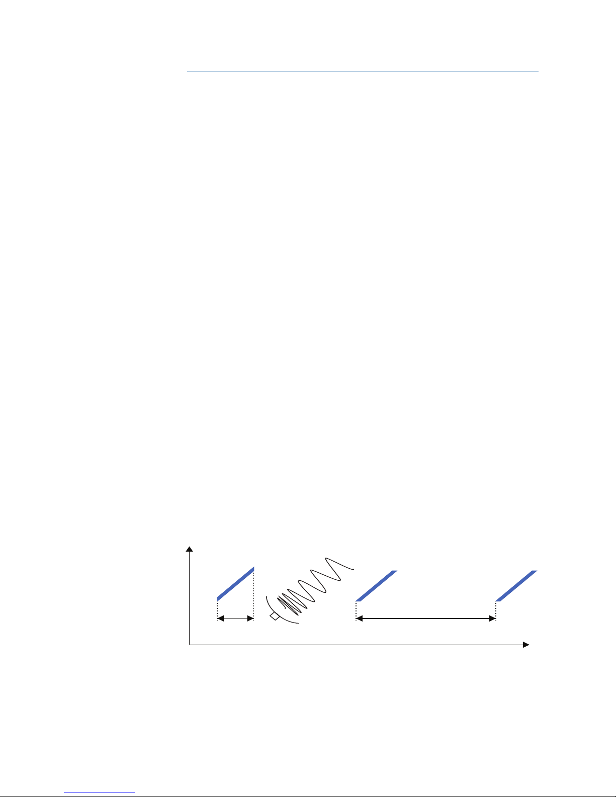
How does FMCW radar work?
1ms 5ms
Time
9.41 GHz
9.4 GHz
Frequency
1
|
7
Radar system overview | Broadband 3G™ Radar Installation Guide
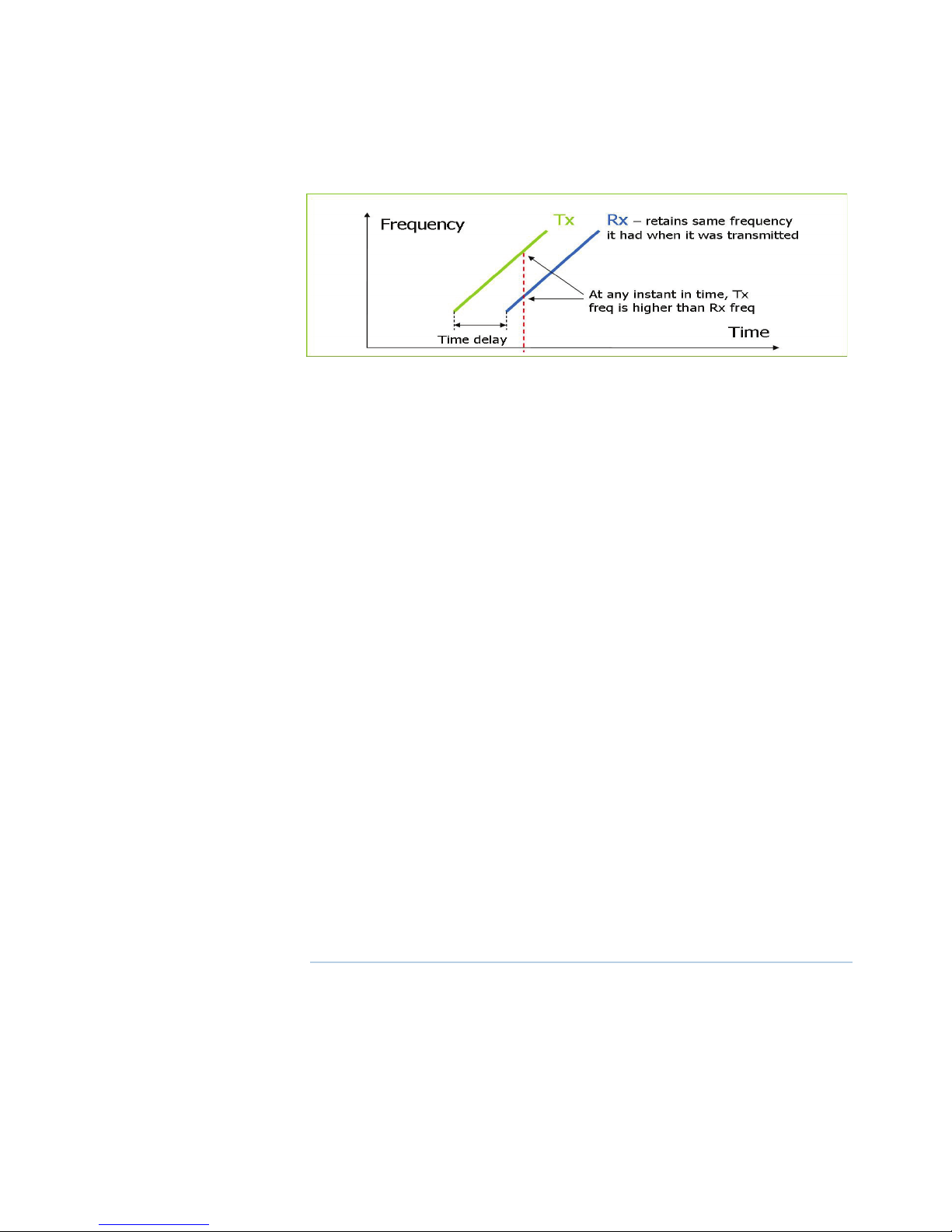
FMCW = Frequency Modulated Continuous Wave
The scanner transmits a ‘rising tone’ (Tx wave) with linearly increasing frequency. The wave
propagates out from the transmitter retaining the frequency it had when it was transmitted. If
it refl ects off an object, it will return to the receiver, still at the frequency it had when originally
transmitted.
Meanwhile, the transmitter continues to output an increasing frequency.
The diff erence between both the currently transmitted and received frequencies, coupled
with the known rate of frequency increase, allows a time of fl ight to be calculated, from which
distance is calculated.
Additional bene ts of FMCW radar are:
Safety-
low energy emissions. 1/10th of a mobile phone
safe operation in anchorages and marinas
instant power up. No warm up required
Short range performance -
broadband radar can see within a few meters of the boat, compared to pulse radars, which
can not see closer than 30 meters
higher resolution clearly separates individual vessels and objects
Up to fi ve times better sea and rain clutter performance
Low power -
suitable for small boats and yachts
easier installation with lighter cabling and smaller connectors
great for yachts on ocean passage
Instant power-up -
conventional radars take 2-3 minutes to warm up the magnetron: Safety – 2 minutes is a long
time if you are concerned about collision.
convenience – switch it on and use it.
Easy to use -
no constant adjusting required to obtain optimum performance
no re-tuning between ranges. Means fast range change at all ranges.
8 |
Radar system overview | Broadband 3G™ Radar Installation Guide
Radar system overview
The Broadband radar is a state of the art navigation aid. It provides outstanding radar performance without the limitations of conventional pulse radars such as: dangerous high power
microwaves, standby warm up time, 30 m blind spot (mainbang), high power consumption
and large open arrays - which is what would be required to obtain the same image quality at
shorter ranges.
The Broadband radar has an eff ective range from 200 ft to 24 nm and has an operating power
consumption of 18 W and stand-by power consumption of 2 W.
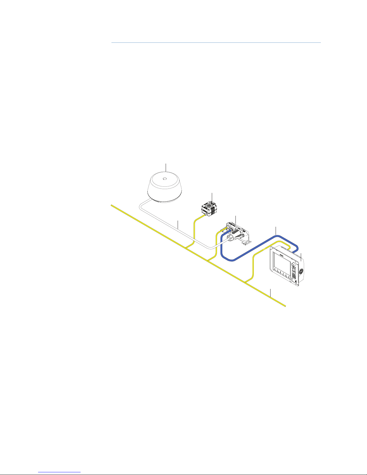
The system consists of: radar scanner (1), an RI10 interface box (3) (not included in USA
model) and an interconnection cable (2). The scanner is housed in a dome of similar size to
most 2 kW radars on the market.
The RI10 interface box is used to connect displays, power and heading information if MARPA
or chart over lay are required (Heading sensor not included). The RI10 has a SimNet (Simrad
NMEA 2000) connector for heading input. The RI10 is included in all kits except Lowrance USA
model (000-10418-001)
1
3
2
4
6
5
7
1. 3G Radar
2. Radar interconnection cable
3. Option heading sensor required for MARPA and chart overlay (not included)
4. RI10 Radar interface box (not included in USA model)
5. Ethernet cable. ships with a 1.8 m (6 ft)
6. Display: Simrad NSO, NSE or NSS / B&G Zeus / Lowrance HDS
7. SimNet or NMEA2000 data network (not included)
2
|
9
Radar system overview | Broadband 3G™ Radar Installation Guide
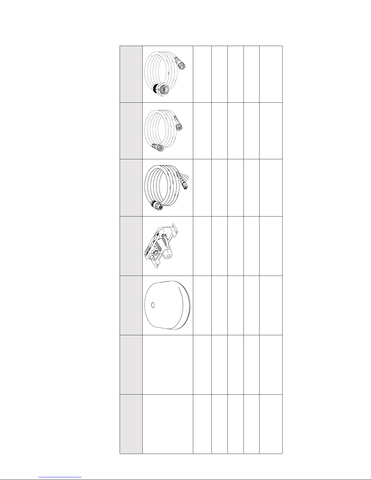
Please take a moment and check the separate packing list to make sure all components have
been supplied
Display Kit Part Number
Broadband 3G™
Radar
RI10
AA010189
Interconnect cable
Ethernet cable 1.8 m
(6ft)
RJ45-5Pin Ethernet
Adapter 2m (6.6 ft)
000-0127-56
Lowrance HDS USA 000-10418-001
10 m (33 Ft)
AA010211
Lowrance HDS ROW 000-10435-001
10 m (33 Ft)
AA010211
Simrad NSO, NSE, NSS 000-10420-001
20 m (65 ft)
AA010212
B&G Zeus 000-10422-001
20 m (65ft)
AA010212
Note: Optional 30 m
(98 ftt) cable available
AA010213
10 |
Installation | Broadband 3G™ Radar Installation Guide
Installation
Note: Follow these instructions carefully. Don’t take any shortcuts!
The broadband radar is factory sealed. It is not necessary to remove the cover. Removing the
cover will void the factory warranty.
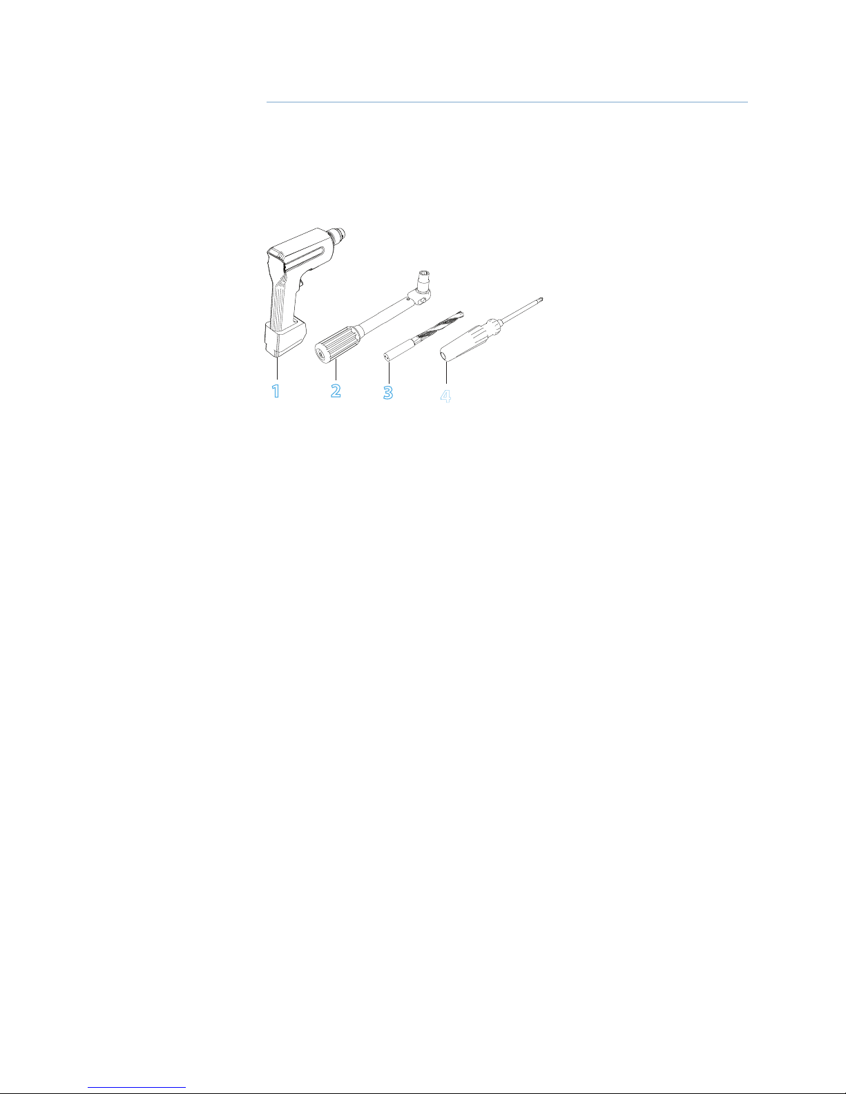
Tools Required
1
2
3
4
Choose the scanner location
The radar’s ability to detect targets greatly depends on the position of its scanner. The ideal
location for the scanner is high above the vessel’s keel line where there are no obstacles.
A higher installation position increases the radar ranging distance, but it also increases the
minimum range around the vessel where targets cannot be detected.
When you’re deciding on the location, consider the following:
The length of the interconnection cable supplied with your radar is usually suffi cient. If you
think you’ll need a longer cable, consult your dealer before installation. Optional cable lengths
are 10 m (33 ft), 20 m (65.5 ft) and 30 m (98 ft).
If you mount the scanner on a pedestal or base, ensure that rain and sea spray can drain away
rapidly, and the breather hole in the base can operate .
The scanner is usually installed parallel to the line of the keel.
DON’T DO THIS!
DON’T install the scanner too high up, which may cause degradation of the radar picture over
short ranges.
DON’T install the scanner close to lamps or exhaust outlets. The heat emissions may damage
the dome. Soot and smoke will degrade the performance of the radar.
DON’T install the scanner close to the antennas of other equipment such as direction fi nders,
VHF antennas, GPS equipment as it may cause interference.
DON’T install the scanner where a large obstruction (such as an exhaust stack) is at the same
level as the beam, because the obstruction is likely to generate false echoes and/or shadow
zones.
DON’T install the scanner where it will be subjected to strong vibrations because these vibrations could degrade the performance of the radar.
DON’T install the scanner such that boat electronics with switch mode power supplies (such
as fi sh-fi nders and chart plotters) are in the beam of the antenna.
DON’T install the scanner directly on to a large fl at roof area. Use a pedestal to elevate the
scanner for radar beams to clear roof line (see “Considerations for direct roof mounting” on
page 11)
1. Drill
2. Torque wrench
3. Drill bit 9.5 mm (3/8”)
4. Screw driver
3
 Loading...