

Page 1
Installation manual
TECHNOLOGY FOR SUSTAINABLE FISHERIES
www.simrad.com
Simrad 38/200 Combi W
Dual frequency echo sounder transducer
Page 2

Page 3

Simrad38/200CombiW
Installationmanual
Thisdocumentprovidesageneraldescriptionofhow
toinstalltheSimrad38/200CombiWDualfrequency
transducer.Theinformationmustberegardedasgeneral
guidelinesandrecommendationsonly.Theinstallation
shipyardmustdesignandmanufactureinstallationhardware
totthe38/200CombiWtransduceroneachindividual
vessel.
Observethemaximumpowerratingsforthis
transducer!
13October2009
164986/D
Page 4

Documenthistory
Kon gs b e rgM a r itim eA S
St ra n d pr om ena d e n5 0
P.O. Box1 11
N- 3 19 1H o rt e n,N o rway
S im ra d
Tele p h on e :+ 473 30 34 00 0
Tele fa x:+ 4 73 30 42 98 7
con t a ct@sim ra d . com
w w w .s im r a d .co m
Documentnumber:164986/ISBN-13:978-82-8066-035-0
Rev.A08.11.04
Rev.B
Rev.C06.06.05
Rev.D
20.05.05
06.10.09
Firstversion.
Addedinformationaboutcableglands.
Correctederrorontheoutlinedimensiondrawingonpage29.
Thecorrectouterdiameteris180mm.
Additionalinformationadded.
Copyright
©2009KongsbergMaritimeAS
TheinformationcontainedinthisdocumentremainsthesolepropertyofKongsbergMaritimeAS.Nopart
ofthisdocumentmaybecopiedorreproducedinanyformorbyanymeans,andtheinformationcontained
withinitisnottobecommunicatedtoathirdparty,withoutthepriorwrittenconsentofKongsberg
MaritimeAS.Thedocument,oranypartofit,maynotbetranslatedtoanyotherlanguagewithoutthe
writtenapprovalfromKongsbergMaritimeAS.
Disclaimer
KongsbergMaritimeASendeavourstoensurethatallinformationinthisdocumentiscorrectandfairly
stated,butdoesnotacceptliabilityforanyerrorsoromissions.
Warning
Theequipmenttowhichthismanualappliesmustonlybeusedforthepurposeforwhichit
wasdesigned.Improperuseormaintenancemaycausedamagetotheequipmentand/orinjury
topersonnel.Theusermustbefamiliarwiththecontentsoftheappropriatemanualsbefore
attemptingtoinstall,operateorworkontheequipment.
KongsbergMaritimeASdisclaimsanyresponsibilityfordamageorinjurycausedbyimproper
installation,useormaintenanceoftheequipment.
Support
Ifyourequiremaintenanceorrepair,contactyourlocaldealer.Y oucanalsocontactususingthefollowing
address:-.Ifyouneedinformationaboutourotherproducts,visitourwebsite.Onthewebsiteyou
willalsondalistofourdealersanddistributors.
Page 5

Installationmanual
Tableofcontents
ABOUTTHISMANUAL.......................................................5
SIMRAD38/200COMBIW................................................6
WHERETOMOUNTTHETRANSDUCER...............................7
HOWTOINSTALLTHETRANSDUCER..............................11
Transducerinstallationinblister............................................................................11
Usemountingandclampingringswheneverprovided...................................11
Smoothsurfaceisimportant........................................................................11
Example:Smallcirculartransducer..............................................................12
Commonguidelines....................................................................................12
Toe-in........................................................................................................13
Physicallocation.........................................................................................13
Transducerinstallationinboxkeel.........................................................................14
Usemountingandclampingringswheneverprovided...................................14
Smoothsurfaceisimportant........................................................................15
Example:Boxkeelinstallation....................................................................15
Transducerushmountedinasteeltank...............................................................15
Usemountingandclampingringswheneverprovided...................................15
Smoothsurfaceisimportant........................................................................16
Waterlled.................................................................................................16
Example:Flushmountinginasteeltank......................................................16
Transducerwithacousticwindow..........................................................................17
Usemountingandclampingringswheneverprovided...................................17
Smoothsurfaceisimportant........................................................................17
Example:Acousticwindow.........................................................................18
Transducermountedinsidethehull.......................................................................18
Usemountingandclampingringswheneverprovided...................................19
Smoothsurfaceisimportant........................................................................19
Example:Mountinginsidethehull..............................................................19
Transducermountedonadropkeel.......................................................................20
Retractabletransducer............................................................................................21
TRANSDUCERCABLEGLANDSANDSPLICING.................22
Aboutcableglands.................................................................................................22
Cableglandforsteelhulls......................................................................................23
CableglandforwoodenandGRPhulls.................................................................24
Cableglandsforsmallhulls...................................................................................25
Transducercablesplicing.......................................................................................26
Ordernumbers........................................................................................................26
STEELCONDUIT..............................................................27
164986/D
3
Page 6

Simrad38/200CombiW
TRANSDUCERHANDLINGANDMAINTENANCE................28
Rulesfortransducerhandling.................................................................................28
Approvedanti-foulingpaints..................................................................................29
Usingself-lockingtaps...........................................................................................29
IntroductiontoEmugeself-lockingthreads...................................................30
Drawingstandard........................................................................................31
Tapsandgauges..........................................................................................31
Self-locktapsprovidedbySimrad...............................................................32
Supplierandmanufacturer...........................................................................32
DRAWINGFILE...............................................................33
Echosounderconnections......................................................................................33
Splicingthetransducercable.......................................................................33
GeneralPurposeTransceiver(GPT)wiring...................................................34
Transducercablepairs.................................................................................34
GeneralPurposeTransceiver(GPT)transducerplugassembly.......................35
Outlinedimensionsandinstallationdrawings........................................................36
Outlinedimensions[208889].......................................................................37
Mountingring[208846]..............................................................................38
Clampingring[204677]..............................................................................40
Recommendedarrangement[204678]..........................................................42
4
164986/D
Page 7

ABOUTTHISMANUAL
Aboutthismanual
Purpose
Thepurposeofthisinstallationmanualistoprovidethegeneric
descriptionsandillustrationsthatallowsyoutounderstandthe
basicprinciplesforechosoundertransducerinstallation.
Caution
Observethemaximumpulsepowerratingforthis
transducer:
•38kHz:400W
•200kHz:250W
Maximumcontinuouspowerratingis:
•38kHz:4W
•200kHz:2,5W
DONOTapplymorepowerthantheratedmaximum!
Exceedingthepowerinputwillpermanentlydamage
thetransducer.
Abouttheinformationprovidedinthisdocument
Theinformationinthisdocumentmustberegardedasgeneral
guidelinesandrecommendationsonly.Theinstallationshipyard
mustdesignandmanufactureinstallationhardwaretoteach
individualtransducerandvessel.
Approvalbymaritimeauthorities
Wheneverrequired,theinstallationshipyardmustalsohavethe
installationapprovedbytheapplicablemaritimeauthorities.
Additionalinformation
Foradditionaldetailedinformationaboutthetransducerto
beinstalled,refertothedocumentationprovidedwiththe
transducer.Drawingsanddescriptionscanalsobeobtainedfrom
t t p : / / w w w . s i m r a d . c o m .
h
164986/D
5
Page 8

Simrad38/200CombiW
SIMRAD38/200COMBIW
Thepurposeofthismanualistheprovidethebasicinformation
requiredtoinstalltheSimrad38/200CombiWDualfrequency
transducer.
Transduceranddocuments
•Simrad38/200CombiW:KSV-208845
•Datasheet:165019
•Drawings:
–Outlinedimensions:834-208889
–Mountingring:499-208846
–Clampingring:820-204677
–Mountingarrangement:820-204678
Note
Althoughdrawingsareprovidedtoexplaintheinstallation
principles,theinstallationshipyardmustprovidethenal
drawingsrequiredtotthetransducertoeachindividual
vessel.Also,whenapplicable,theinstallationshipyardmust
havethedrawingsandinstallationapprovedbytheproper
maritimeauthorities.Thedrawingsspecicforthe38/200
CombiWtransducerarelocatedintheDrawingleon
page33.
Technicalspecications
RefertotheSimrad38/200CombiWdatasheet.Y oucanread
and/ordownloadthedatasheetonh t t p : / / w w w . s i m r a d . c o m .
Additionalpartsprovidedforinstallation
ThefollowingitemscanbesuppliedbySimradtofacilitate
installation.Theitemsmustbeorderedseparately.
•Mountingring:ES1-208847
•Clampingring:ES1–203672
•Transducercable(forextension):642-078215
6
164986/D
Page 9

WHERETOMOUNTTHETRANSDUCER
Wheretomountthetransducer
Asingleanswertothequestionwheretolocatethetransducer
cannotbegiven.Itdependsverymuchonthevessel’s
construction,howthehullisshapedandhowthewaterruns
alongthehull.Therearehoweveranumberofimportantguide
lines,andsomeoftheseareevenconicting.
Mountthetransducerdeep
Mountthetransduceratadeeppositiononthehull.Considerthe
situationswhenthevesselisunloaded,andwhenitispitching
inheavyseas.
Thereareseveralreasonsforthis.
1Theupperwaterlayersoftheseacontainamyriadofsmall
airbubblescreatedbythebreakingwaves.Inheavyseasthe
upper5to10metresmaybelledwithair,andthehighest
concentrationswillbenearthesurface.Airbubblesabsorb
andreectthesoundenergy,andtheymayinworstcases
blockthesoundtransmissionaltogether.
2Anotherreasontogodeepisthecavitationinfrontof
highpowertransducers.Cavitationistheformationof
smallbubblesinthewaterduetotheresultinglocal
pressurebecomingnegativeduringpartsoftheacoustic
pressurecycles.Thecavitationthresholdincreaseswiththe
hydrostaticpressure.
3Thetransducermustneverbeliftedfreeofthewatersurface.
Transmittingintoopenairmaydamagethetransducer
beyondrepair.Mountingthetransduceratadeepposition
onthehullpreventsthis.
4Ifthetransducerisliftedupfromthewaterduringheavy
seas,itmaybedamagedwhenthehullstrikesbackatthe
seasurface.Thisisespeciallyimportantforlowfrequency
transducerswithlargefaces.
Mountthetransducerawayfromprotruding
objectsonthehull
Objectsprotrudingfromthehull,suchaszincanodes,sonar
transducersoreventhevessel’skeel,generateturbulenceand
ownoise.Holesandpipeoutletsarealsoimportantnoise
sources.Theymayactasresonantcavitiesamplifyingtheow
noiseatcertainfrequencies.Donotplaceanechosounder
transducerinthevicinityofsuchobjects,andespeciallynot
closebehindthem.Forthesamereason,itisveryimportant
thatthehullareaaroundthetransducerfaceisassmoothand
levelaspossible.Eventracesofsealingcompound,sharpedges,
protrudingboltsorboltholeswithoutllingcompoundwill
createnoise.
164986/D
7
Page 10
Simrad38/200CombiW
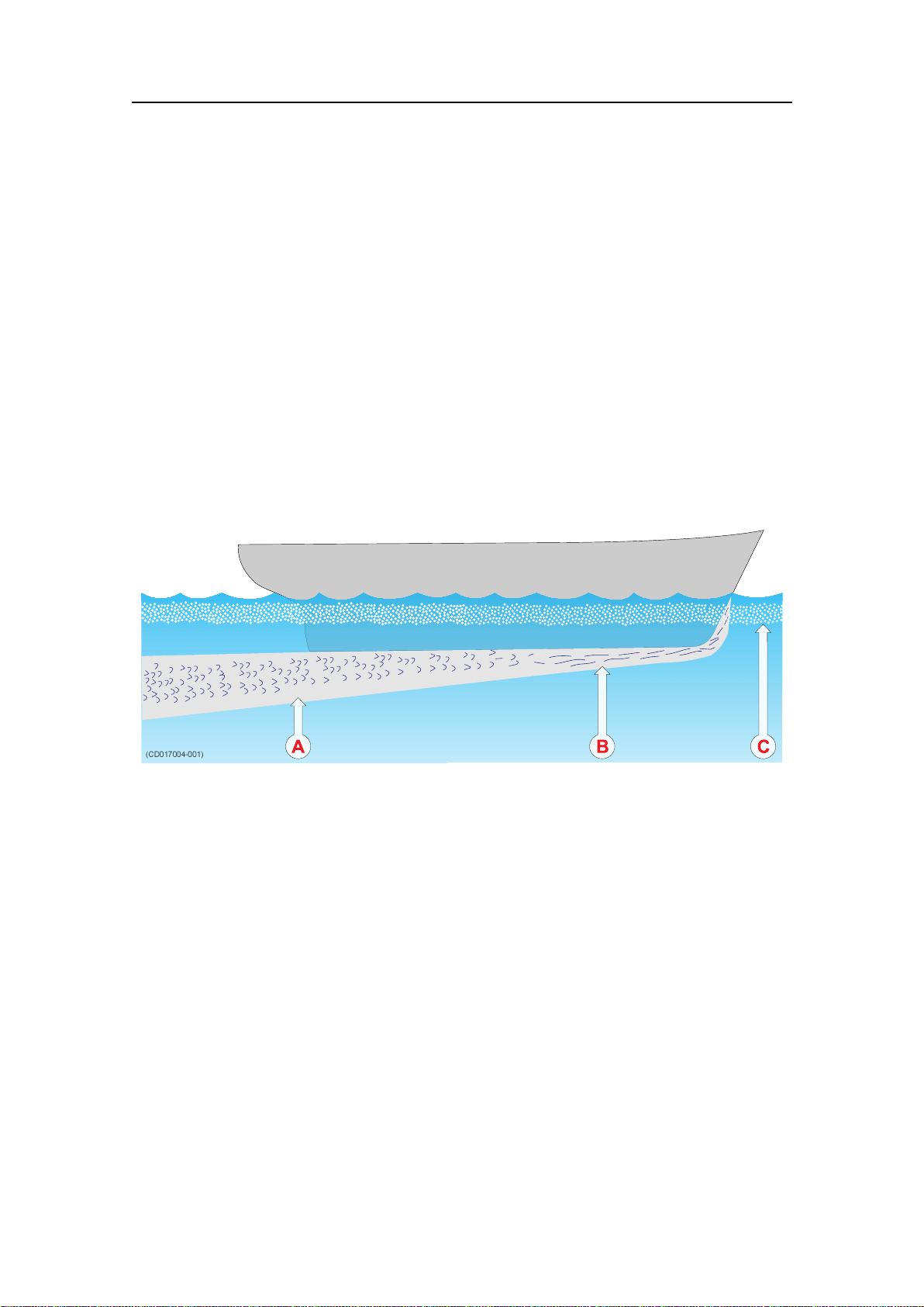
Figure1Boundarywaterlayer
Mountthetransducerattheforwardpartofthe
hulltominimisetheeffectsfromtheboundary
waterlayer
Whenthevesselforcesitswaythroughthesea,thefriction
betweenthehullandthewatercreatesaboundarylayer.The
thicknessoftheboundarylayerdependsuponvesselspeedand
theroughnessofthehull.Objectsprotrudingfromthehull,and
dentsinthehull,disturbtheowandincreasethethicknessof
theboundarylayer.Theowinthisboundarylayermaybe
laminarorturbulent.Alaminarowisanicelyordered,parallel
movementofthewater.Aturbulentowhasadisorderlypattern,
fullofeddies.Theboundarylayerincreasesinthicknesswhenthe
owgoesfromlaminartoturbulent.Thegurebelowillustrates
theboundarylayerofavesselmovingthroughthewater.
ATurbulentow
BLaminarow
CAirbubblesinthewater
Furthermore,airbubblesintheseawaterarepresseddownbelow
thehullandmixedintotheboundarylayer.Theboundarylayer
isthinunderneaththeforwardpartofthevessel,andincreasesin
thicknessasitmovestowardsaft.Ifthesidesofthehullaresteep,
someoftheairbubblesintheboundarylayermayescapetothe
seasurfacealongthevesselsides.Itisourexperiencethatawide
andatbottom,witharisinganglelessthanaround13degrees,
ispronetogivingairproblemsforthetransducer.Inanycasea
transducerlocationintheforwardpartofthehullispreferredin
ordertominimisetheinuenceoftheboundarylayer.
8
164986/D
Page 11

Wheretomountthetransducer
Mountthetransducerfarawayfromthepropellers
Thepropulsionpropelleristhedominantnoisesourceonmost
shingvessels,researchvessels,merchantvesselsandpleasure
crafts.Thenoiseistransmittedthroughtheseawater.For
thisreason,thetransducershouldbeplacedfarawayfromthe
propeller,whichmeansontheforepartofthehull.Positions
outsidethedirectlineofsightfromthepropellerarefavourable.
Onsmallvesselswithshortdistancesitisadvisedtomountthe
transduceronthatsideofthekeelwherethepropellerblades
moveupwards,becausethepropellercavitationisstrongeston
theotherside.Thecavitationstartsmosteasilywhenthewater
owsinthesamedirectionasthepropellerblade,andthatisto
somedegreethecaseatthatsideofthekeelwherethepropeller
bladesmovedownwards.
Mountthetransducerfarawayfromthebow
thrusters
Bowthrusterpropellersareextremelynoisy.Wheninoperation,
thenoiseandcavitationbubblescreatedbythethrustermake
theechosounderuseless,almostnomatterwherethetransducer
isinstalled.Andwhennotinoperation,thetunnelcreates
turbulence,andifthevesselispitching,thetunnelmaybelled
withairoraeratedwaterintheupperpositionandreleasethisin
thelowerposition.Ingeneral,alltransducersmustbetherefore
placedwellawayfromthebowthruster.However,thisisnot
aninvariablerule.Certainthrusterdesignscombinedwithits
physicallocationonthehullmaystilloffersuitabletransducer
locationsnearthethruster.Ifyouareindoubt,consultanaval
architect.
Mountthetransducerwithaslightlyinclined
transducerface
Ideally,thetransducerfaceshouldbemountedinparallelwiththe
seasurfacewhenthevesselisinnormaltrim,asthiswillprovide
themostaccurateechoinformation.However,itisalsovery
importantthatthew
a t e r o w overthetransducerfaceislaminar.
Inordertoensurelaminarow,thetransducerfacemaybetilted
slightlyupwardsinrelationtothewaterow.Thisallowsthe
owingwatertomeetthefacedirectly,andassureslaminarow.
Theinclinationanglemusthoweverbedeterminedcarefully.The
anglemustbesmallontransducerswithnarrowbeamangles.As
aruleofthumb,mounttransducerswithbeamanglessmaller
thansevendegreeswithminimuminclinationangle.Thesmaller
beamangleyourtransducerhas,thesmallertheinclinationangle
canbe.Ensurethatyoudonotmountthetransducerwitha
negativeinclinationangle.Thismaycauseturbulenceunderthe
transducerface,andreducedechosounderperformance.
164986/D
9
Page 12
Simrad38/200CombiW
Summaryandgeneralrecommendations
Someoftheaboveguidelinesareconicting,andeachcasehas
tobetreatedindividuallyinordertondthebestcompromise.
Generallythepropellernoiseisthedominantfactor,anda
recommendedtransducerlocationisintheforepartofthehull,
withmaximumdistancefromthebowequaltoonethirdofthe
totallengthofthehullatthewaterline.
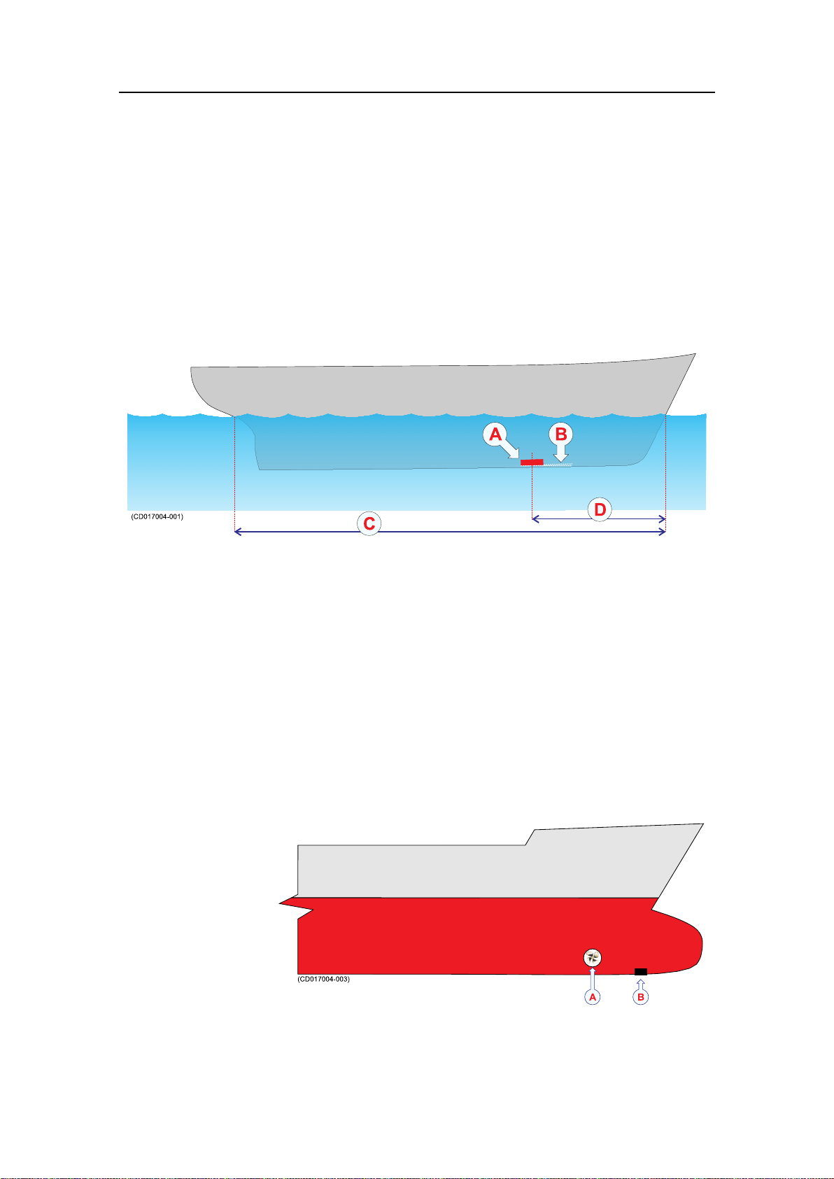
Figure2Generalrecommendationfortransducerlocation
ATransducer
BInclinationangle
CHulllengthatwaterline
DMaximum1/3ofthehulllengthatwaterline(C)
Ifthevesselhullhasabulbousbow,thismaywellbeagood
transducerlocation,butalsoheremustbetakenintoconsideration
theowpatternoftheaeratedwater.Oftentheforemostpart
ofthebulbispreferable.
Figure3Recommendedlocationofthetransduceronabulbous
hull
AThruster
BTransducerlocation
10
164986/D
Page 13

HOWTOINSTALLTHETRANSDUCER
Therearemanydifferentwaystomountthetransducer.These
aretherecommendedmethodstomountacirculartransducer.
Transducerinstallationinblister
Withatransducerwithcircularhousing,onerecommended
installationmethodisbyusingablister.Thetransducerblister
mustbedesignedandmanufacturedbytheinstallationshipyard
totthevessel’ssizeandhullshape.
Usemountingandclampingrings wheneverprovided
Circulartransducersmaybeprovidedwithmountingand
clampingrings,orwithdrawingstoallowforlocalproduction
ofthese.Themountingringisweldedtotheholepreparedfor
thetransducer,whiletheclampingringtsaroundtheedgeof
thetransducerbody.Boltsthroughtheclampingringintothe
mountingringwillsecurethetransducerbetweenthem.Note
thatseveraltransducersusedirectionguidestoallowcorrect
mounting.
Howtoinstallthetransducer
Smoothsurfaceisimportant
Mountingscrewsorboltsmustnotbeextrudingfromthe
transducerortheareaimmediatelyaroundit.Makesurethatthe
surfaceofthetransducerface,theinstallationhardwareusedto
mountit,thehullplatingandtheputtyaroundthetransduceris
asevenandsmoothaspossible.Obstructionsonthesesurfaces
willcreateproblemswithturbulentow.
164986/D
11
Page 14
Simrad38/200CombiW
E
E
A
C
G
D
F
B
(CD017010B)
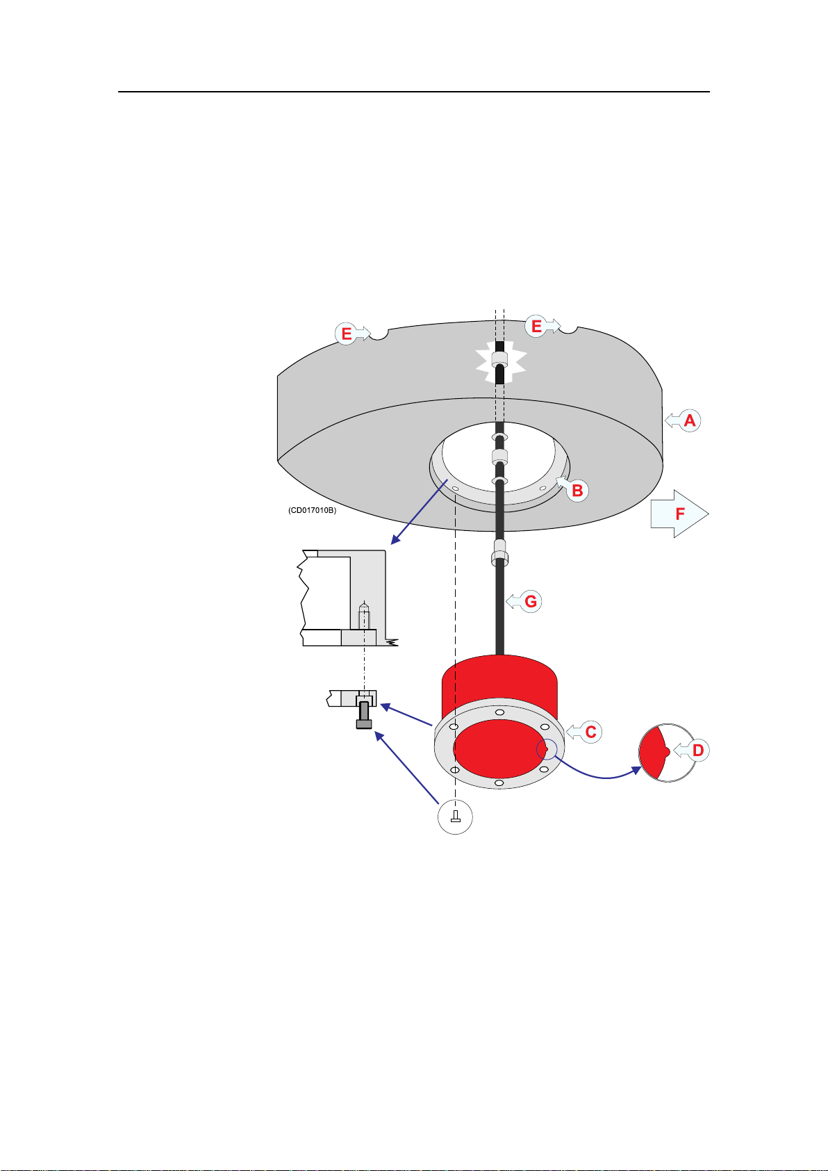
Figure4Smallcirculartransducer
Example:Smallcirculartransducer
Theillustrationbelowshowsatypicaltransducerblisterdesigned
forasmalltransducer.Thesameblisterdesignprinciplesasfora
largetransducerapply.
AStreamlined
blister
BMountingring
CClampingring
DGuide
EAiroutlet
FForward
GTransducer
cable
Notethatthetransducercablemustbeprovidedwithacableloop
insidetheblister.Observetheverticalforwardedgeoftheblister.
Thiswillguidethewatertoeachsideoftheblister.
Commonguidelines
Thebestperformanceisobtainedwithablisterheightof40cm
ormore.Astreamlinedshapeandroundededgesreducetheow
noise.Averticalleadingedgeorfrontwillguidetheaerated
watertothesidesoftheblister.Theorientationoftheblister
shouldfollowthewaterow.
12
164986/D
Page 15
Howtoinstallthetransducer
(CD17010C)
A
B
C
Theinterioroftheblistermustbelledwithseawater.Use
drainageholesinthebottomandanairoutletonthetop.The
waterpressurebehindthetransducerwillthencompensatefor
theoutsidepressureduringvesselmovementsinroughsea.
Werecommendthatlargediametertransducersarettedwitha
horizontalU-shapedsupportbar.Thisbarcanthenbesecured
tothemountingringusingthreadedrods.
Thetransducercablepenetratesthehullinastufngtube.Leave
anadequateloopofthecablebehindthetransducerforeasy
mountingorremovalofthetransducer.
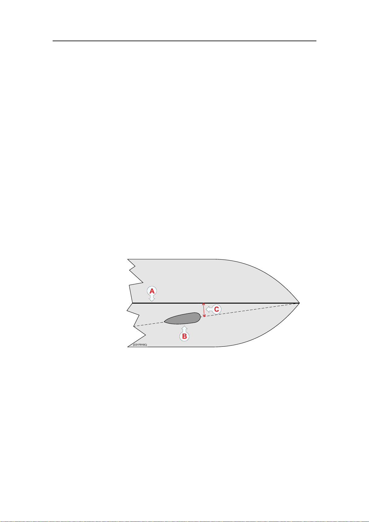
Toe-in
Theprimaryconsiderationmustbetoallowlaminarwaterow.
Inmostcasesthisisachievedbydesigningtheblisterinparallel
withthekeel.However,iftheblisterislocatedclosetothebow ,
thefrontoftheblistermayhaveafewdegreestoe-intowards
thebow.
Figure5Toe-inprinciple
AKeel
BBlister
CT oe-inangle
Theanglemustbechosentoallowformostefcientwaterow.
Itwillvarywiththelocationofthetransducer;thedepthbelow
thehull,thedistancefromthebow,andthedistancetothekeel.
Typicalanglesarefrom0to3°ondeplacementhulls.Onplaning
hulls,theangleisnormallycloseto0°.
Physicallocation
Theblisterisplacedononeofthesidesofthehull,andthe
distancefromthekeelisatradeoffbetweenaclosedistance
givingaturbulentowofwaterinanarrowpassage,andalarge
distancebringingthetransducerhigherupandalsomoreaffected
byvesselroll.Normallyadistanceofapproximately1misa
goodcompromise.
164986/D
13
Page 16

Simrad38/200CombiW
AKeel
BTransducer
blister
CHorizontal
distance
betweenkeel
andblister
DVertical
distance
betweenthe
blistersurface
andthekeel
Observethehorizontalandverticaldistances(CandD)between
thekeelandthetransducerblister.Onamediumsizedvessel,the
horizontaldistance(C)shouldbeapproximately1meter.The
verticaldistance(D)mustingeneralbeassmallaspossible.This
isimportanttopreventthekeelfromshadowingthetransducer
beaminshallowwaters.
Transducerinstallationinboxkeel
Vesselswithaboxkeelmayusethisfortransducerinstallation.
Theboxkeelisalreadythedeepestpartofthevessel.Ifthe
boxkeelistoonarrowtoaccommodatethetransducer,itcanbe
widened,eithersymmetricallyortoonesideonly.Inthelast
casetheinstallationcouldalsobedescribedasablistermerged
intothekeel.
Usemountingandclampingrings wheneverprovided
Circulartransducersmaybeprovidedwithmountingand
clampingrings,orwithdrawingstoallowforlocalproduction
ofthese.Themountingringisweldedtotheholepreparedfor
thetransducer,whiletheclampingringtsaroundtheedgeof
thetransducerbody.Boltsthroughtheclampingringintothe
mountingringwillsecurethetransducerbetweenthem.Note
thatseveraltransducersusedirectionguidestoallowcorrect
mounting.
14
164986/D
Page 17

Figure6Boxkeelinstallation
(CD1701
1A)
A
B
D
C
E
ABoxkeel
BU-shaped
support
bar(only
recommended
onlarge
transducers)
Howtoinstallthetransducer
Smoothsurfaceisimportant
Mountingscrewsorboltsmustnotbeextrudingfromthe
transducerortheareaimmediatelyaroundit.Makesurethatthe
surfaceofthetransducerface,theinstallationhardwareusedto
mountit,thehullplatingandtheputtyaroundthetransduceris
asevenandsmoothaspossible.Obstructionsonthesesurfaces
willcreateproblemswithturbulentow.
Example:Boxkeelinstallation
Thegurebelowillustratesasymmetricalboxkeelinstallation.
CStufngtube
DCableinsteel
conduit
ECableservice
loop
Transducerushmountedinasteeltank
Flushmountingisusedonverylargevesselswithahullsodeep
thatnoairbubblesarefoundbelowthehull,andonvessels
operatinginshallowharboursorwaters,whereaprotruding
blistercannotbeaccepted.
Thestandardprocedureforushmountingonasteelvesselis
toweldasteeltankinsidethehull,andmountthetransducer
intothistank.
Usemountingandclampingrings wheneverprovided
Circulartransducersmaybeprovidedwithmountingand
clampingrings,orwithdrawingstoallowforlocalproduction
ofthese.Themountingringisweldedtotheholepreparedfor
thetransducer,whiletheclampingringtsaroundtheedgeof
thetransducerbody.Boltsthroughtheclampingringintothe
164986/D
15
Page 18

Simrad38/200CombiW
(CD17012A)
B
A
G
C
D
E
F
mountingringwillsecurethetransducerbetweenthem.Note
thatseveraltransducersusedirectionguidestoallowcorrect
mounting.
Smoothsurfaceisimportant
Mountingscrewsorboltsmustnotbeextrudingfromthe
transducerortheareaimmediatelyaroundit.Makesurethatthe
surfaceofthetransducerface,theinstallationhardwareusedto
mountit,thehullplatingandtheputtyaroundthetransduceris
asevenandsmoothaspossible.Obstructionsonthesesurfaces
willcreateproblemswithturbulentow.
Waterlled
Asforablister,theinteriorofthetankmustbelledwithwater.
Thiscanbeaccomplishedbyairreleasethroughasteeltube,
whichisextendedeithertoopenair1.5mabovethewaterline
ortothewateroutsidethehullatapointhigherthanthetank
interior.
Ifthetubeisextendedtoopenair,drainagemustbeprovided
withleakageatthetransducerangeoraseparateholeinthe
tankbottom.
Example:Flushmountinginasteeltank
Transducermountinginasteeltankisshowninthegurebelow .
Figure7Flushmountinginasteeltank
ASteeltank
BWater
CDrainagehole
DCableservice
loop
ESteeltubefor
airoutlet
FStufngtube
GCableinsteel
conduit
16
164986/D
Page 19

Transducerwithacousticwindow
Vesselsoperatinginarcticwatersneedspecialattentionon
transducerinstallation.Floatingblocksoficemaydamageeven
aushmountedtransducerface.ForthissituationSimradoffers
arctictanksindifferentsizes.
Usemountingandclampingrings wheneverprovided
Circulartransducersmaybeprovidedwithmountingand
clampingrings,orwithdrawingstoallowforlocalproduction
ofthese.Themountingringisweldedtotheholepreparedfor
thetransducer,whiletheclampingringtsaroundtheedgeof
thetransducerbody.Boltsthroughtheclampingringintothe
mountingringwillsecurethetransducerbetweenthem.Note
thatseveraltransducersusedirectionguidestoallowcorrect
mounting.
Howtoinstallthetransducer
Smoothsurfaceisimportant
Mountingscrewsorboltsmustnotbeextrudingfromthe
transducerortheareaimmediatelyaroundit.Makesurethatthe
surfaceofthetransducerface,theinstallationhardwareusedto
mountit,thehullplatingandtheputtyaroundthetransduceris
asevenandsmoothaspossible.Obstructionsonthesesurfaces
willcreateproblemswithturbulentow.
164986/D
17
Page 20

Simrad38/200CombiW
(CD017012B)
B
A
C
G
D
E
F
Figure8Acousticwindow
ASteeltank
BOil
CAcoustic
window
Example:Acousticwindow
Thetransducershowninthegurebelowismountedinsidethe
tankbehindastrongacousticwindowwhichcouldbemadeof
polycarbonate.
Thetankislledwithoil.
DCableservice
loop
EStufngtube
FCableinsteel
conduit
GOilinlet
Transducermountedinsidethehull
Thetransducercanalsobemountedinsidethehull.
Aninstallationofthetransducerinsidethehull,andsounding
throughthehull,requiresagoodacousticcontactbetweenthe
transducerfaceandthehull.Buildatankaroundthetransducer
andllitwithaliquid.Oilusedinhydraulicsystemsisawell
suitedliquidforthispurpose.Itcontainsnogasbubblesand
isnon-corrosive.
Typicalvaluesofthetwowaylossare3dBforpolyester,6dB
foraluminiumand10dBforsteel.Hullsmadeofwoodora
sandwichtypewithfoaminthemiddle,attenuatethesoundso
muchthatthroughhullsoundingmustberegardedasimpossible.
Thelossvarieswiththedistancebetweentransducerfaceand
thehull.Thebestresultisobtainedwhenthedistanceishalfa
wavelength.ConsultSimradforadvice.Inadditiontotheloss,
thebeampatternisdegraded,becausealargerareaofthehullis
setintovibrations.
18
164986/D
Page 21

Howtoinstallthetransducer
(CD017012C)
B
A
C
D
E
F
G
H
Usemountingandclampingrings wheneverprovided
Circulartransducersmaybeprovidedwithmountingand
clampingrings,orwithdrawingstoallowforlocalproduction
ofthese.Themountingringisweldedtotheholepreparedfor
thetransducer,whiletheclampingringtsaroundtheedgeof
thetransducerbody.Boltsthroughtheclampingringintothe
mountingringwillsecurethetransducerbetweenthem.Note
thatseveraltransducersusedirectionguidestoallowcorrect
mounting.
Smoothsurfaceisimportant
Mountingscrewsorboltsmustnotbeextrudingfromthe
transducerortheareaimmediatelyaroundit.Makesurethatthe
surfaceofthetransducerface,theinstallationhardwareusedto
mountit,thehullplatingandtheputtyaroundthetransduceris
asevenandsmoothaspossible.Obstructionsonthesesurfaces
willcreateproblemswithturbulentow.
Figure9Mountinginsidethehull
ASteeltank
BOil
CHullplating
DCableservice
loop
EStufngtube
FCableinsteel
conduit
GHoleforoil
lling
HAiroutlet
Example:Mountinginsidethehull
Thetransducershowninthegurebelowismountedinsidethe
hull.Thetankislledwithoil.
164986/D
19
Page 22

Simrad38/200CombiW
(CD017012D)
B
C
A
Transducermountedonadropkeel
Theuseofadropkeelwiththepurposeofstabilisingthevessel
iswellknown.
Adropkeelisalsoasuperiorplatformforechosounder
transducers.Suchinstrumentkeelshavebeenbuilt,mainlyon
researchvessels,oftenprotrudingasfarasthreemetersbelow
thehull.Atthatdepth,thewaterisfreeofairbubblesupto
veryhighseastates.Thevesselisthenabletoperformreliable
acousticmeasurementsinopenseaalargerpartoftheyear.
AInstrumentkeelshaft
BLoweredposition
CBottomview
20
164986/D
Page 23

Retractabletransducer
(CD017012E)
B
E
C
D
A
Howtoinstallthetransducer
Hullunitsallowingthetransducertobeloweredandhoistedare
commonlyusedforhorizontallookingsonars.Whennotinuse,
thetransducerisretractedintoatrunk.
Theretractablehullunitismoreexpensivethanablister,buton
vesselswithahullwhereitisdifcultorimpossibletoinstalla
blister,itmaystillbeworthwhile.Theprinciplesofahullunit
witharetractabletransducerisshownbelow.
Vesselswithoutakeelandwithawide,atbottomisanexample
wherearetractablehullunitcanbetheonlyacceptablemethod
forbringingtheechosoundertransducerbelowtheboundary
layer.
ATransducer
BTrunk
CTransducer
shaft
DTransducer
shaftsleeve
EKeel
164986/D
21
Page 24

Simrad38/200CombiW
TRANSDUCERCABLEGLANDSANDSPLICING
Thetransducercablemustpassthroughthehullusingapproved
cableglandsforthetypeofvesselinquestion.
Aboutcableglands
Asteelcableglandisnormallyusedonprofessionalvessels
withsteelhulls.Abronzecableglandcanbedeliveredasan
optionforvesselswithwoodorbreglasshulls.V esselnottobe
classiedcanasanoptionuseacableglandmadeofplastic.
Note
Simradstronglyrecommendsthatalengthofconduitistted
aroundtransducercableglandsmadeofsteelorbronzeand
extendedoverthewater-lineinsidethevessel.Thisprecaution
reducesthedangerofoodingintheeventofglandfailureand
transducersinstalledinthismannerarealsoeasiertoreplace.
Somevesselsmayexperiencedifcultiesndingsuitableareas
ofthehullformountingtransducercableglandsduetoexisting
watertanks,concreteballastorotherobstacles.Apossible
solutioninsuchcasesistorunthetransducercablesinasteel
conduitaftalongthehulluntilasuitablecableglandlocationis
available.Therespectivecableglandcanthenbeinstalledas
describedinthefollowinginstructions.
Note
Simradtakesnoresponsibilityforthecorrectinstallationof
cableglands,associatedhullmodicationsand/orstructural
supportoftransducercablepenetration.Theseactivitiesare
subjecttoindividualapprovalbytherespectiveclassication
societyforthevesselinquestion.
22
164986/D
Page 25

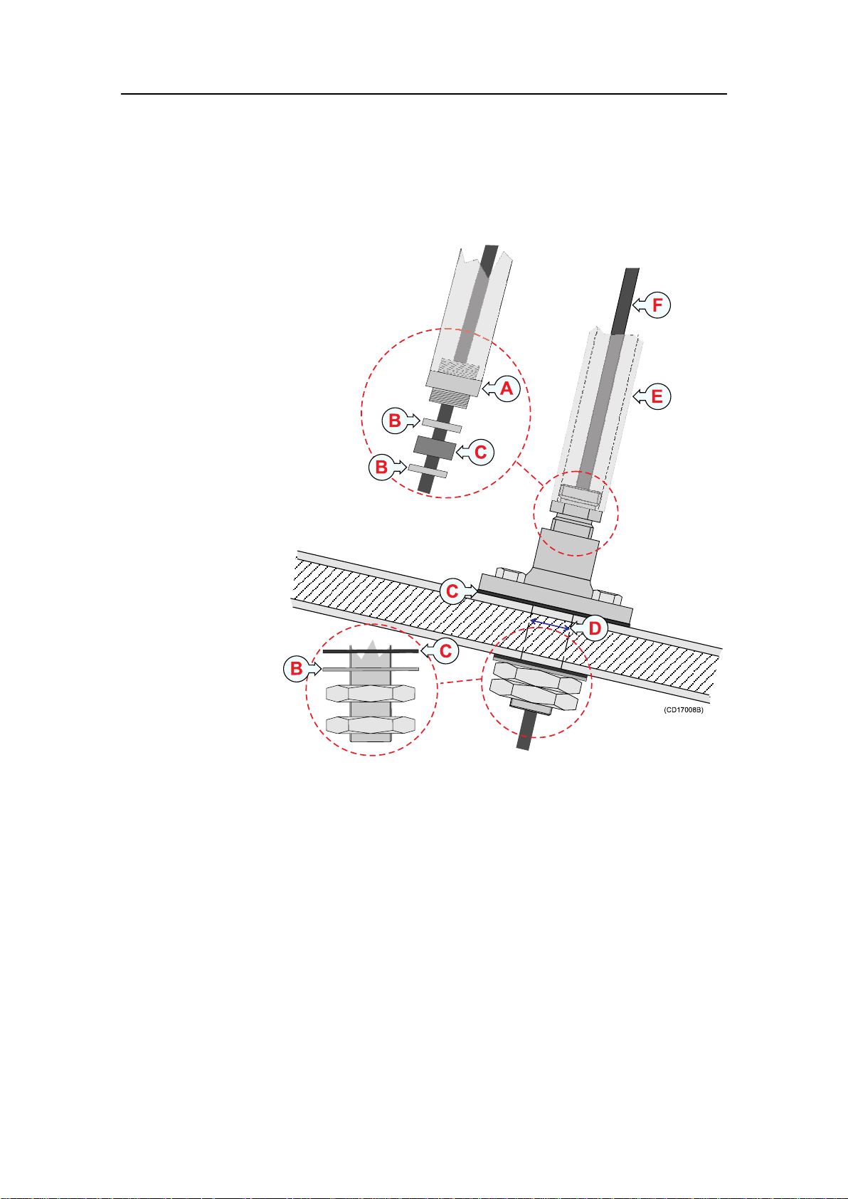
Cableglandforsteelhulls
(CD17008A)
ø35
ø65
A
A
B
C
C
D
E
F
Thiscableglandkitisdesignedforsteelvessels.Itmustbe
weldedtothehullplates.
Transducercableglandsandsplicing
ASteelconduit
BStufngtube,DNVapprovedcarbonsteelst52.3
CW ashers
DRubbergasket
EPackingnipple.Makesurethatyoudonotdamagethe
transducercablebytighteningthepackingnippletoohard!
FCabletotheechosounder(orajunctionbox)
Thecableglandkitincludesallofthenecessarypartsneededto
installtheunitexceptscrews.
Simradrecommendsthataoneinchsteelconduit(thatthe
transducercablewillberunthrough)withaninsidethreaded
diameterofthree-quarterinchesisweldedtothegland’sstufng
tube.Theconduitmustextendtoabovethevessel’swaterline.
164986/D
23
Page 26
Simrad38/200CombiW
A
B
B
B
C
C
C
D
E
F
CableglandforwoodenandGRPhulls
Abronzecableglandkitisavailableforwoodenand
glass-reinforcedplastic(GRP)vessels.
APackingnipple.Makesurethatyoudonotdamagethe
transducercablebytighteningthepackingnippletoohard!
BWashers
CRubbergaskets
DHolediameter28mm
ESteelconduit
FCabletotheechosounder(orajunctionbox)
Thecableglandkitincludesallofthenecessarypartsneededto
installtheunitexceptscrews.
Simradrecommendsthataoneinchsteelconduit(thatthe
transducercablewillberunthrough)withaninsidethreaded
diameterofthree-quarterinchesisattachedtothegland’spacking
nipple.Thisconnectionmustbewatertight,andtheconduitmust
extendtoabovethevessel’swaterline.
24
164986/D
Page 27

Cableglandsforsmallhulls
(CD17008C)
A
A
J
B
C
D
G
E
F
H
I
Thiscableglandsmadeofplasticisdesignedforthosesmaller
vesselsthatdonotneedtobeclassied.
Transducercableglandsandsplicing
APackingnut(bronze).Makesurethatyoudonottodamage
thetransducercablebytighteningthepackingnuttoohard!
BRubbergasket
CPlasticdisk
DRubbergasket
EStufngtube
FBackingnut(bronze)
GBackingwasher(plastic)
HO-ring42.5x3.0N
IO-ring39.5x3.0N
JCabletotheechosounder(orajunctionbox)
Stufngtubeholediameter:36mm±1.5mm.
Applyampleamountofsealantbetweenthebackingwasher(H)
andthehullplate.
Thecableglandkitcontainsallthelistedparts,exceptthesealant.
Note
ThetwoO-ringsmustbeclean,ingoodconditionandfreeofcuts
orotherdefectswhichcouldaffecttheirwatertightintegrity.
164986/D
25
Page 28

Simrad38/200CombiW
Transducercablesplicing
Ifyouneedtocutorlengthenthetransducercable,youmust
spliceitcorrectly .Thecablebetweenthejunctionboxandthe
transceivermustthenbesuppliedbySimrad,andthismustbe
thesametypeasusedonthetransducer(s).Tosplicethecable,
useametaljunctionboxwithEMCcableglandsandaterminal
block.Theterminalblockmustprovidesolidfasteningofthe
cableendsaswellassufcientinsulationbetweenthewires.We
recommendthatthecablescreenisconnectedtothejunction
boxchassisusingtheEMCcableglands,butifyoudothis,the
junctionboxchassism
Note
D o n o t solderthewirestogetherwithonlyelectricaltapefor
insulation.Thiswillresultinelectricalnoiseandreduced
operationalperformance.
u s t n o t beconnectedtovessel’sground.
o n o t connectthecablescreentothevessel’ sground.
D
Ordernumbers
Thecableglandsdescribedinthischapterareavailableaskits
fromSimrad.Observethefollowingordernumbers.
HulltypeItem
SteelCableglandkit,steel,8to15mmcables
SteelCableglandkit,steel,17to18,5mmcables
Wood/GRPCableglandkit,bronze
SmallCableglandkit,plastic
Ordernumber
499–037763
305609
119-038200
599-202182
26
164986/D
Page 29

Steelconduit
STEELCONDUIT
Whyusesteelconduits?
Itisstronglyrecommendedtolayasteelconduitfromthe
transducer’scableglandtotheechosoundertransceiver,andto
pullthetransducercablethroughthisconduit.Thereareseveral
reasonsforthis.
•Itwillmakeiteasieratalaterstagetoreplacethetransducer.
•Noiseandinterferencefromotherelectricalequipmentis
greatlyreduced.
•Theriskofoodingisgreatlyreducedifthepipeisterminate
abovethewaterline.
WithasteelconduittheinstallationwillsatisfytheEU
regulationsforEMCinterference.Withoutasteelconduit,there
isariskofreducedechosounderperformance.
Steelconduitsqualitiesandshielding
Thesteelconduitmustbeunbrokenandwatertightfromthe
transducertoabovethewaterline.Fromthere,thecablecan
bepulledfurther,orajunctionboxcanbeinstalledtofacilitate
furtherconnections.Notethatthesteelconduitmustactasa
continuouselectricalscreenalltheway.
Steelconduitdimensions:
•minimum35mminnerdiameter
•minimum6mmwallthickness(4.5mmifgalvanised)
Morethatonetransducercable?
Iftwoormoretransducersareinstalledclosetoeachotheritis
possibletopulltheircablesinthesamesteelconduit,provided
theconduitdiameterisincreasedaccordingly.However,foreasy
replacementitisrecommendedthateachtransducerhasitsown
steelconduit.
164986/D
27
Page 30

Simrad38/200CombiW
TRANSDUCERHANDLINGAND MAINTENANCE
YouMUSTobservethefollowingrulesforhandling,
maintenanceandpainting.
Rulesfortransducerhandling
Note
Donotliftthetransducerbythecable.
Donotexposethetransducertodirectsunlight.
Donotexposethetransducertoexcessiveheat.
Transportprotection
Sometransducersaredeliveredwithacoverplateontheface
forprotectionduringtransport.Letthisplatestayonaslongas
possible,butdonotforgettoremoveitbeforethevesselgoes
intothesea.
Paintingthetransducerface
Ananti-foulingpaintmaybeappliedtothetransducerface.
Becausesomepainttypesmaybeaggressivetothepolyurethane
inthetransducerface,pleaseconsultSimrad’slistofapproved
paints.SeeApprovedanti-foulingpaintsonpage29.
Cleaningthetransducerface
Wheneveropportunityarise,forexamplewhenthevesselisdry
docked,thetransducerfacemaybecleanedforshellsandother
marinefouling.B
f a c e . Useapieceofsoftwoodoraverynegradeemerypaper.
Specialrulesforacousticwindows
Arctictankshaveacousticwindowsmadeofpolycarbonate.
T
h e s e m u s t n e i t h e r b e p a i n t e d n o r c l e a n e d w i t h c h e m i c a l s .
Acousticwindowsmustnotbeexposedtodirectsunlight.
e c a r e f u l n o t t o m a k e c u t s i n t h e t r a n s d u c e r
28
164986/D
Page 31

Approvedanti-foulingpaints
ThisisSimrad’slistofapprovedantifoulingpaintson
polyurethanetransducerhousing.
Jotun
Headofceaddress:P .O.Box2021,N-3248Sandefjord,Norway
Transducerhandlingandmaintenance
Website:w
w w . j o t u n . c o m .
1Racing
2Non-stop
3SafeguardUniversalprimer(125micron)withAntifouling
SeaQuantumUltra(125micron)
4AntifoulingSeaguardian
InternationalMarineCoatings
Address:W orld-wideofces
Website:w
w w . i n t e r n a t i o n a l - m a r i n e . c o m .
1Intersleektiecoat+425FCS
•BXA386/BXA390/BXA391Grey
•HKA563/HKA570/HKA571Yellow
•MixBXA386,BXA390andBXA391rst,thenapply.
Whendry,mixHKA563,HKA570andHKA571,apply.
2Intersmooth360EcoloexSPC
3MicronExtra
HempelIFACoatings
Usingself-lockingtaps
164986/D
Headofceaddress:HempelA/S,Lundtoftevej150,Kgs.
Lyngby ,DK-2800Copenhagen,Denmark
Website:w
w w . h e m p e l . c o m .
1HempelA/FClassic76550
Note
Refertothemanufacturer’ sdocumentationanddatasheetsfor
acompleteprocedure.
Screwconnectionsaregenerallymadesothattheycanbe
loosenedagain.However,accidentalloosening,especiallyunder
dynamicstress,mustbeavoided.Forthisreasonitisoften
necessarytouseadditionallockingdevices.Theseareoften
expensive,theycanbeusedonceonly,orreactcriticallyto
temperaturechanges.
29
Page 32

Simrad38/200CombiW
A B C
2
1
(CD017020B)
IntroductiontoEmugeself-lockingthreads
Emugeself-lockisatapdesignwithanintegratedlockingfeature.
Standardmetricboltsareused.Theinternalthreadprovidesa
self-lockingconnection,whichcanbeusedrepeatedly.Itisnot
necessarytoinvolveasecondarylockingdevice(e.g.chemical,
nylonormechanical).TheEmugeself-lockboltswithstand
vibrationsbetterthanstandard(metric)threads,becausethe
threadcontactstopsthesidewaysmovement.Thespecial
designoftheinternalthreadprolealsoprovidesamoreeven
distributionofthetighteningstressoverthewholethreadlength.
Theassemblyisjustaseasyaswithanormal(metric)thread.
Thereisnogeneralapplicablestandard(e.g.DINstandard)for
theEmugeself-lockthread.
Figure10Example,internalandexternalthreads
AEmuge’ ssaw-toothproleuptopitchP≤0.7mm
BEmuge’ ssaw-toothproleuptopitchP≥0.7mm
CStandardthread
1Externalthread
2Internalthread
Advantages
•Thethreadlockingfeatureisintegratedintheinternalthread
•Modiedprolewithrampsurfaceinthedirectionofstress
•30degreerampsurfaceprovidesself-lockingeffect
•Easyassembly
•Noassemblyerrors(forgettingthelockingdevice)possible
•Useofstandardexternalthreads(screws)withtoleranceclass
“medium”
•Evendistributionofstressoverthewholethreadlength
•Nostrippingofthreads
30
164986/D
Page 33
Transducerhandlingandmaintenance
M8SL*
M10SL*
(CD017020A)
•Economicallyefcientlockingsystem,noadditional
componentsarenecessary
•Undiminishedholdingpowerevenunderdynamicstress
•Repeatedlooseningandre-tighteningwithoutlossoffunction
•InternalthreadscanbeproducedwithEmugetaps,cold
formingtapsorthreadmills
•Largerthreadholediameters,i.e.increasedtoollifefor
threadingtools
•Largertolerancesforthreadholediameters
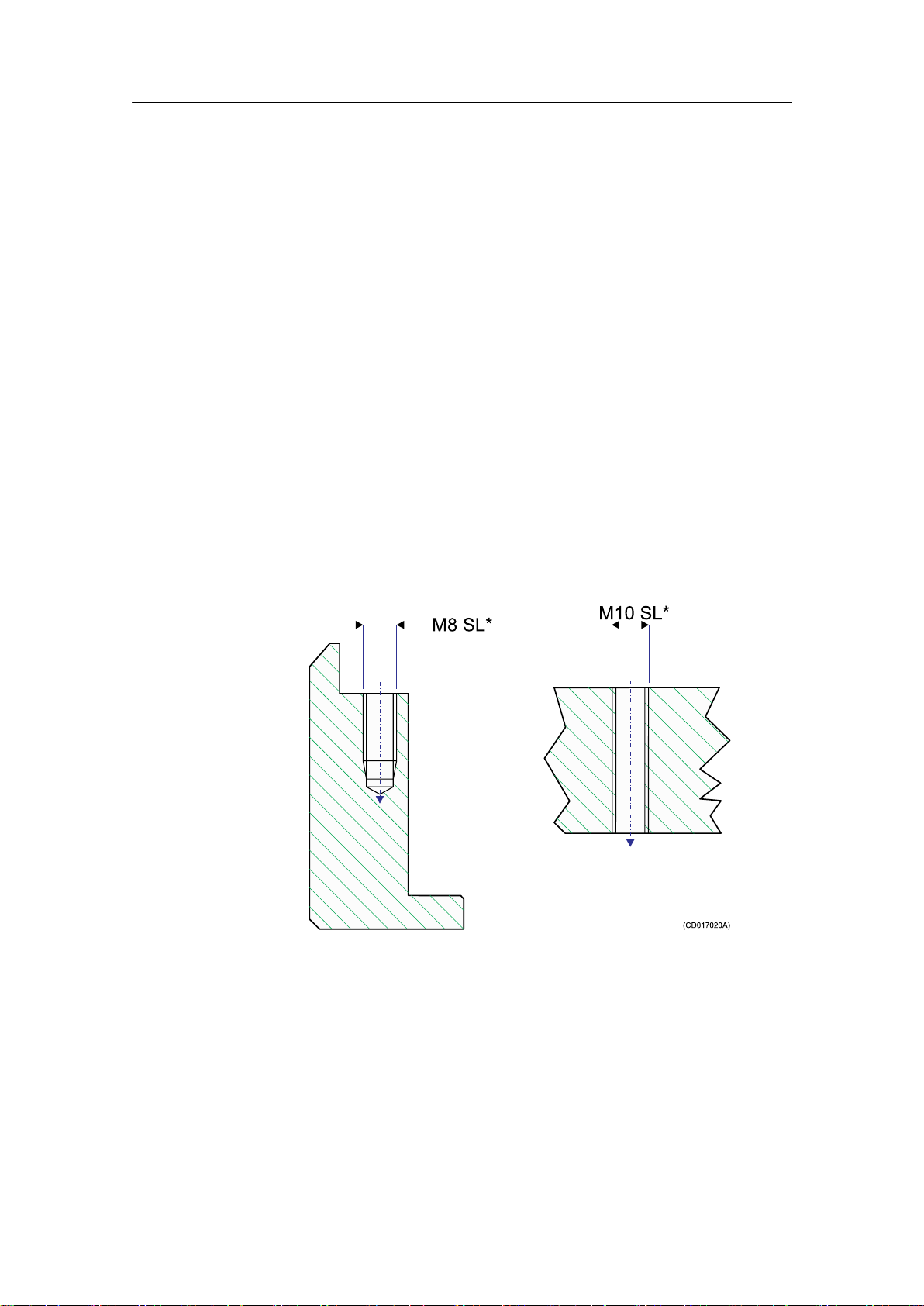
Drawingstandard
Wheneverself-lockingthreadsarerequired,thisisshownon
thetechnicaldrawing.Inthecaseoftappingthroughholes,
thearrowattheendofthecenterlineillustratesthescrew-in
directionofthebolt.
Figure1 1Drawingexamples,self-lockingthread
Thedrawingisnormallyprovidedwiththefollowingtext(or
similar):
Note:Theself-lockthreadsmarkedwithSL*mustbemadein
accordancewithprocedure842–202125.Drilldiametersfor
threadsdifferfromstandard.Self-locktapscanbesuppliedby
Simrad.
Tapsandgauges
Thepretensionlockingthreadself–lock(taps)frommanufacturer
Emugemustbeused.
164986/D
31
Page 34

Simrad38/200CombiW
(CD017020C)
Figure12Exampleofuse
Note
Inthecaseoftappingthroughholesitisimportantthatthe
proleoftheEmugeself-lockthreadsisinthecorrectdirection
comparedwiththeenteringdirectionofthebolt.
UseEmugeself-lockgauges.Notethatthegaugemustbeused
inthecorrectdirection.
Self-locktapsprovidedbySimrad
Thefollowingself-locktapsareonstockatSimrad,andcanbe
orderedfromus.
Threads
M6ø5.2700-078838
M8ø7.0700-078531
M10ø8.8700-078408
M12ø10.7700-078409
M16ø14.5700-078410
Drilldiameterfor
threads
Part.no
Supplierandmanufacturer
Norwegiansupplieris:
TingstadAS,P.O.Box83,Kalbakken,0902Oslo,Norway
h
t t p : / / w w w . t i n g s t a d . n o
Manufactureris:
EMUGE-WerkRichardGlimpel,NurnbergerStrasse96-100,
D-90607Lauf,Germany
h
t t p : / / w w w . e m u g e . d e
32
164986/D
Page 35

DRAWINGFILE
Drawingle
Thischaptercontainsrelevantdrawingsrelatedtotheelectrical
andphysicalinstallationoftheSimrad38/200CombiWDual
frequencytransducer.
Note
Themechanicaldrawingsareforinformationandguidanceonly.
Theyarenotinscale,andmaydifferslightlyfromtheoriginal
drawings.Alldimensionsareinmmunlessotherwiseisnoted.
TheoriginalinstallationdrawingsareavailableonPDFand/or
DWG(AutoCad)format.Visitw
Topics
•Echosounderconnectionsonpage33
w w . s i m r a d . c o m todownload.
Echosounderconnections
•Outlinedimensionsandinstallationdrawingsonpage36
Observethefollowinginformationrelatedtoelectrical
connectionofthe38/200CombiWDualfrequencytransducer.
Splicingthetransducercable
Ifyouneedtosplicethetransducercable,itisveryimportant
tousethecorrectcable,andtoavoidgroundloops.Westrongly
recommendtheuseofajunctionbox.W ealsorecommendthat
youinstallthetransducercableinasteelconduit.
Formoreinformation,see:
•Transducercablesplicingonpage26
•Steelconduitonpage27
•GeneralPurposeTransceiver(GPT)transducerplug
assemblyonpage35
164986/D
33
Page 36

Simrad38/200CombiW
M
E
F
J
H
D
C
K
L
A
B
N
Transducer
cable
JunctionBox(1:1)
(Optional)
GPT Transducer
socket
W802-6
Rev.E
Dualfrequency ,singlebeamtermination
J
D
H
C
Screen
Black
Black
Black
Black
White
White
White
White
Connecttoplughousing
4
17
"Auxiliary"25-pin
D-connectoronGPT
Thermistor
Thermistor
Notused
Lowfrequency
Lowfrequency
Highfrequency
Highfrequency
Pair1
Pair2
Pair3
Pair4
Black
Black
Black
Black
White
White
White
White
P 1air :38kHz
P 2air :200kHz
P 3air : Thermistor
P 4air :Spare(notused)
Thepairnumberisprintedontheblackconductor .
Transducer
cable
(CD017000-008)
GeneralPurposeTransceiver(GPT)wiring
ObservethedrawingbelowtoconnecttheSimrad38/200Combi
WDualfrequencytransducertotheGeneralPurposeTransceiver
(GPT).Formoreinformationabouttheseconnections,referto
theapplicableechosounderinstallationmanual.
Transducercablepairs
Thisillustrationshowsthewiringinsidethetransducercable,and
howtoidentifytheindividualcablepairs.
Figure13Cabletermination,38/200CombiWDualfrequency
transducer
34
164986/D
Page 37

GeneralPurposeTransceiver(GPT)
Rubbersleeve
Rubbersleeve
Retainingring
Contactbody
Plug
fasteningring
Upperplugcase
Bottomcap
andcableclamp
Washers
Heat-shrinkabletubing
Lowerplugcase
Outerscreentogetherwithinnerscreen.
Drainwire,foldbackoverjacket
andtemporaryfastenedwithtape.
Outerscreenandinnerscreenbraidwire
untapedandspreadoutunderwasher
CD010219APage1of1
824-201575Rev .C
Note:
Allmeasurementsareinmm.
Thedrawingisnotinscale.
transducerplugassembly
Drawingle
164986/D
35
Page 38

Simrad38/200CombiW
Outlinedimensionsandinstallationdrawings
Note
Observethe32Nmtorquewhenthetransducerismountedusing
themountingandclampingrings.
Observethe17Nmmaximumtorquewhenthetransduceris
mountedusingthethreadedinsertsonthetransducerbody.
Topics
•Outlinedimensions[208889]onpage37
•Mountingring[208846]onpage38
•Clampingring[204677]onpage40
•Recommendedarrangement[204678]onpage42
36
164986/D
Page 39

Allmeasurementsinmm.
Thedrawingisnotinscale
834-208889Rev .B
CD017000-004Page1of1
ø130
ø180
ø152
80
100.2
85.2
Use12mm
M8bolts
Weightwithoutcable:2,4kg
Threadedinserts
forportableuse
Drawingle
Outlinedimensions[208889]
164986/D
37
Page 40

Simrad38/200CombiW
198
60degrees
M10
(Sixholes)
ø0.2
30degrees
Allmeasurementsinmm.
Thedrawingisnotinscale
499-208846Rev .A
CD017000-009Page1of2
Mountingring[208846]
38
164986/D
Page 41

Drawingle
15
+0.3/-0
R0.5
R0.75(max)
20
+2/-2
30
+1/-1
6.3
ø181
+0.5/-0
ø222
+0.5/-0
ø226
+1/-1
109.3
+1/-1
ø240
+1/-1
ø122
+1/-1
84.3
+0.1/-0
0.075
Chamfer
3x45degrees
45degrees
Allmeasurementsinmm.
Thedrawingisnotinscale
499-208846Rev .B
CD017000-010Page2of2
164986/D
39
Page 42

Simrad38/200CombiW
Clampingring[204677]
40
164986/D
Page 43

Drawingle
164986/D
41
Page 44

Simrad38/200CombiW
Recommendedarrangement[204678]
42
164986/D
Page 45

Drawingle
164986/D
43
Page 46

Simrad38/200CombiW
Index
A
About,5
informationinthis
manual,5
Acousticwindow,28
example,18
installation,17
Additionalinformation,5
Anti-fouling
paint,29
Approval
maritimeauthorities,5
Arrangement
drawing,42
B
Blister
Commonguidelines,12
installation,11
physicallocation,13
Boundarywaterlayer,8
Bowthrusters
noise,9
Boxkeel
example,15
installation,14
C
Cable
transducer,splicing,26
Cablegland
about,22
GRPhull,24
smallhull,25
steelhull,23
woodenhull,24
Cableglands
ordernumbers,26
Clampingring
blister,11
drawing,40
Clampingrings,11,14–15,
17,19
Cleaning
transducerface,28
Commonguidelines
blister,12
Conduit
steel,27
D
Diameter
steelconduit,27
Dimensions
drawing,37
Drawing
arrangement,42
Clampingring,40
GPTTransducerplug,35
mountingarrangement,42
Mountingring,38
outlinedimensions,37
Drawingle,33
Dropkeel
installation,20
E
EMCinterference,27
Emuge,30
Example
Acousticwindow,18
boxkeel,15
ushmounting,16
Insidethehull,19
F
Flushmounting
example,16
steeltanl,15
G
GeneralPurpose
Transceiver
transducerplug,35
wiring,34
Glass-reinforcedplastic
hull
cablegland,24
GPT
wiring,34
GPTTransducerplug
drawing,35
Groundloops
avoiding,33
GRPhull
cablegland,24
H
Handling,28
Handlingrules,28
Heat,excessive
doNOTexpose,28
HempelIF ACoatings,29
Hullunit
installation,21
I
Inclination
angle,9
Insidethehull
example,19
installation,18
Installation
drawings,6,33
hardware,6
responsibility,6
Installationmethod
Acousticwindow,17
Blister,11
Boxkeel,14
Dropkeel,20
Flushmounting,15
Hullunit,21
Insidethehull,18
Retractable,21
Steeltank,15
InternationalMarine
Coatings,29
Introduction,6
J
Jotun,29
Junctionbox
cablesplicing,33
L
Lifting,28
Location
recommendation,10
M
Maintenance,28
Maritimeauthorities
approval,5
Mountingarrangement
drawing,42
Mountingring
blister,11
drawing,38
Mountingrings,11,14–15,
17,19
N
Noise
boundarywaterlayers,8
bowthrusters,9
propeller,9
44
164986/D
Page 47

Index
protrudingobjects,7
O
Ordernumber
transducer,6
Ordernumbers
cableglands,26
Outlinedimensions
drawing,37
P
Paint
anti-fouling,29
Painting
transducerface,28
Physicaldimensions
drawing,37
Physicallocation
blister,13
Propeller
noise,9
Protrudingobjects,7
Purpose
thismanual,5
R
Retractable
installation,21
Termination
cable,34
GPT,34
Toe-in,13
Transducer
lifting,28
ordernumber,6
recommendedlocation,10
Transducercable
pairs,34
splicing,26,33
termination,34
Transducerface
cleaning,28
painting,28
Transducerplug
drawing,35
Transportprotection,28
W
Waterlled
steeltank,16
Wiring
GeneralPurpose
Transceiver,34
Woodenhull
cablegland,24
S
Self-lockingtaps,30
Shielding
steelconduit,27
Simradwebsite,5
Smoothsurface,11,15–17,19
Splicing
transducercable,26,33
Steelconduit
diameter,27
qualities,27
shielding,27
why,27
Steelhull
cablegland,23
Steeltank
ushmounting,15
waterlled,16
Sunlight
doNOTexpose,28
Surface
smooth,11,15–17,19
T
Taps,self-locking,30
164986/D
45
Page 48

ISBN-13:978-82-8066-035-0
Kon gs b e rgM a r itim eA S
St ra n d pr om ena d e n5 0
P.O. Box1 11
N- 3 19 1H o rt e n,N o rway
S im ra d
Tele p h on e :+ 473 30 34 00 0
Tele fa x:+ 4 73 30 42 98 7
con t a ct@sim ra d . com
w w w .s im r a d .co m
©
2009KongsbergMaritimeAS
 Loading...