

Page 1
AC & DC
Digital Multimeter
589681
3
Multimètre numérique
Digital Multimeter
DC Voltage / Tension c.c. / Gleichspannung /
Tensión c.c. / Tensione CC / Gelijkspanning
Overload protection: 220V rms AC for 200mV
range and 500V DC or 500V rms for all ranges
Range Resolution Accuracy
200mV
2000mV 1mV
20V 10mV
200V 100mV
500V 1V ± (1.2% of read-
DC Current / Intensité c.c. / Gleichstrom /
Corriente c.c. / Corrente CC / Gelijkstroom
Overload protection: 0.5A/500V and 5A/500V fuse
Range Resolution Accuracy
200µA 100nA
2000µA 1µA
20mA 10µA
200mA 100µA
5A 10mA
AC Voltage / Tension c.a. / Wechselspannung /
Tensión c.a. / Tensione CA / Wisselspanning
Overload protection: 500V DC or 500V rms for all ranges
Range Resolution Accuracy
200V 100mV
500V 1V
Resistance / Résistance / Widerstand /
Resistencia / Resistenza / Weerstand
Overload protection: 15 seconds maximum 220V rms
Range Resolution Accuracy
200 Ω 0.1m Ω
2000 Ω 1 Ω
20 Ω 10 Ω
200K Ω 100 Ω
2000K Ω 1K Ω
100µV
Digitalmultimeter
± (0.5% of reading + 3 digits)
± (1.0% of reading + 5 digits)
ing + 5 digits)
± (1.8% of reading
+ 2 digits)
± (2.0% of reading
+ 2 digits)
± (2.0% of reading
+ 10 digits)
± (1.2% of reading +
10 digits)
± (1.0% of reading
+ 10 digits)
± (1.0% of reading
+ 2 digits)
Multímetro digital
Multimetro digitale
Digitale multimeter
Audible Continuity/ Continuité audible/ Akustische
Durchgangsprüfung/ Continuidad audible/ Continuità udibile/
Hoorbare continuïteit
Overload protection: 15 seconds maximum 220V rms
Range Description
Built-in buzzer sounds if resistance is less than 30 ± 20 Ω
Transistor hFE test (0-1000)/ Test de valeur hFE de transistor (0-1000)/
Transistor-(hFE)-Test (0–1000)/ Prueba de transistores hFE (0-1000)/
Transistor hFE test (0000-1000)/ Transistor HFE test (0-1000)
Range Test Range Test Current Test Voltage
NPN & PNP 0-1000 1b - 10µA Vce = 3V
Range Resolution Accuracy Overload
Plage Résolution Précision protection
Bereich Auflösung Genauigkeit Überlast-
Escala Resolución Precisión Protección
Inter-
Risoluzi-
vallo
one
Bereik Resolutie Nauw
Precisione protezione
keurigheid
Protection
surcharge
schutz
contra
sobrecargas
sovraccarico
Overbelasting
beveiliging
+/- 0.5%
of reading
+/- 5
digits
+/-0,5 %
de la valeur
+/- 5
chiffres
+/- 0,5%
v. M. +/- 5
Digits
+/-0,5%
de lectura
+/- 5 dígitos
+/- 0,5%
lettura
+/-5 cifre
+/- 0,5%
van lezing
+/- 5
cijfers
Test
Range
Plage
d’essai
Prüfbereich
Escala de
prueba
Prova
gamma
Test
bereik
2
1
8
Test Current Test Voltage Built-in buzzer
Intensité
d’essai
Prüfstrom Prüfspan-
Intensidad
de prueba
Prova
Corrente
Test gelijkstroom
Tension
d’essai
nung
Tensión de
prueba
Prova
Tensione
Test
spanning
sounds if
resistance is
less than 30 ±
20 Ω
Le signal
sonore retentira
si la résistance
est inférieure à
30 ± 20 Ω
Eingebauter
Signalton
ertönt, wenn
der Widerstand
unter 30 ± 20
Ω liegt
Se oye la señal
sonora cuando
la resistancia
es inferior a 30
± 20 Ω
Segnale acustico incorporato
se la resistenza
è minore di 30
± 20 Ω
Ingebouwd
alarm luid
wanneer de
weerstand
onder de 30/20
Ω reikt
7
Overload protection:
0.5A/500V and
5A/500V fuse
Protection
surcharge : fusible
0,5 A / 500 V et 5
A / 500 V
Überlastschutz:
0,5 A/500 V und
5 A/500-VSicherung
Protección contra
sobrecargas :
fusible 0,5 A / 500
V y 5 A / 500 V
Protezione
da sovraccarico: 0.5A/500V e
5A/500V fusibile
Overbelastingsbeveiliging: 0,5
A/500 V en 5
A/500 V zekering
4
5
6
220V rms AC for 200mV
range and 500V DC or
500V rms for all ranges
220 V c.a. pour plage
de 200 mV et 500
Vc.c. ou 500 V rms
pour autres plages
220V Effektivwert
(RMS) Wechselspannung (AC) für
200-mV-Bereich und
500 V Gleichspannung (DC) oder 500 V
Effektivwert (RMS) für
alle Messbereiche
220 V c.a. para escala
de 200 mV y 500 V
c.c. ó 500 V rms para
otras escalas
220 V ca per la
gamma di 200 mV e
500 V cc o 500 V rms
per tutte le gamme
200Vms AC voor
200mV bereik en 500
V DC of 500V RMS
voor andere bereiken
www.silverlinetools.com
Page 2
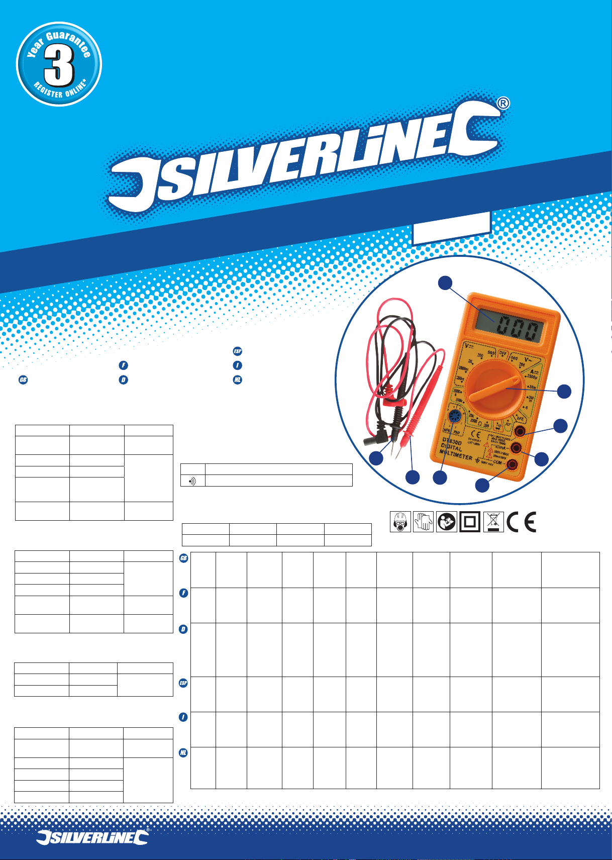
1) Positive Lead
2) Negative Lead
3) LCD Display
4) Function Selector
5) 5A DC Jack
6) VΩmA Jack
7) Common Jack
8) hFE Socket
As part of our ongoing product development, specifications of Silverline
products may alter without notice
ACCURACY
Accuracy is specified for a period of one year after calibration and within
temperature range 18° - 28°C with 80% max relative humidity
Before Use
Unpacking
Ensure that all parts of your multimeter are present and in good condition.
If any part is missing, or damaged, have such parts replaced before
attempting to use this tool
Assembly
1. Remove the two screws from the back of the multimeter.
2. Take the back off and insert a 9V battery.
3. Connect the battery - align the battery with the connector so that the
terminals on the battery and the connector snap-fit together securely.
4. Insert the battery into the compartment, replace the panel carefully
and re-tighten the screws.
SPECIFICATION
Battery type: 9V
DC voltage: 200mV - 1000V
AC voltage: 200 - 750V
DC current: 200μA - 5A
Resistance: 200 ohm - 2000k ohm
Operating
NOTE:
• Every time this multimeter is used, inspect the test leads, connectors
and probes for damage. If the leads are damaged have them replaced
by an authorised service centre
• If in doubt as to range required, select the highest range and then
reduce it as necessary until satisfactory resolution is obtained
• If the figures ‘1’ or ‘-1’ are displayed, this indicates the reading is out of
the set range
Voltage measurement
•Connect the red Positive Lead (1) to the VΩmA Jack (6)
•Connect the black Negative Lead (2) to the COM (Common) Jack (7)
• Rotate the Function Selector (4) to select the required voltage range in
the correct DC or AC range
•Connect the test leads to the circuit being measured
• Turn on the power to the circuit being measured. The value of the
voltage passing through the circuit should be displayed on the LCD
Display (3), along with the polarity (if reversed only)
DC Current measurement
•For measurements up to 200mA: Connect the red Positive Lead (1) to
the VΩmA Jack (6)
• For measurements above 200mA, up to max 5A: Connect the red
Positive Lead (1) to the 5A Jack (5). Please note the 5A circuit is unfused
•Connect the black Negative Lead (2) to the COM (Common) Jack (7)
•Rotate the Function Selector (4) to select the required amperage range
• Make the circuit being measured open, connect the test leads across the
opening to create a bridge over the gap
• Turn on the power to the circuit being measured, the value of the current
passing through the circuit should be displayed on the LCD Display (3)
Resistance measurement
NOTE: If the resistance to be measured is part of a circuit, turn off and
disconnect the power and discharge all capacitors before measurement.
•Connect the red Positive Lead (1) to the VΩmA Jack (6)
•Connect the black Negative Lead (2) to the COM (Common) Jack (7)
•Rotate the Function Selector (4) to select the required ohm range
•Connect the test leads to the circuit being measured
•The resistance value should now be displayed on the LCD Display (3)
NOTE: While measuring resistance about 1MΩ and above, the meter may
take a few seconds to stabilise. This is normal for high resistance readings.
Diode testing
•Connect the red Positive Lead (1) to the VΩmA Jack (6)
•Connect the black Negative Lead (2) to the COM (Common) Jack (7)
•Rotate the Function Selector (4) to the setting
•Connect the red test lead to the anode of the diode to be tested and the
black test lead to the cathode of the diode
•The approx. forward voltage drop of the diode should be displayed on
the LCD Display (3)
NOTE: If the connection is reversed, only figure ‘1’ will be displayed
Continuity testing
•Connect the red Positive Lead (1) to the VΩmA Jack (6)
•Connect the black Negative Lead (2) to the COM (Common) Jack (7)
•Rotate the Function Selector (4) to the setting
•Connect the test leads to the circuit being measured
• If continuity exists (i.e. resistance is less than approx. 50Ω), the built-in
buzzer will sound
Transistor testing
•Rotate the Function Selector (4) to the ‘hFE’ position
•Determine whether transistor is NPN or PNP
•Locate the emitter, base and collector leads
•Insert the leads into the appropriate holes in the ‘hFE’ Socket (8): The left
side of the socket is configured for PNP, the right side for NPN
•The approximate hFE value will be displayed on the LCD display at the
testing condition of base current 10μA and Vce 3V
Test signal use
•Rotate the Function Selector (4) to the setting
•A test signal (50Hz) appears between VΩmA and COM jack, the output
voltage is approx to 5V p-p with 50KΩ impedence
Storage and Maintenance
WARNING: Ensure that the test leads are disconnected prior to storing or
carrying out any maintenance on this tool
• Store the unit in a clean, dry environment within the temperature range
-10°C to +50°C
• If the test leads are damaged in any way, replace them with new leads
of the same type and specification
•If the unit malfunctions, have it serviced by a suitably qualified
technician
•If you need to replace the battery, use method described in ‘Assembly’
EC Declaration of Conformity
The undersigned: Mr Darrell Morris
as authorised by: Silverline Tools
Declares that the
Name/ model: Digital Multimeter
Type/ serial no: 589681
Conforms to the following Directives:
• Low Voltage Directive 2006/95/EC
• EMC Directive 2004/108/EC
• EN61010-1:2001
• EN61010-031:2002+A1:2008
• EN61326-1:2006
• EN61326-2-2:2006
The technical documentation is kept by: Silverline Tools
Notified body: Shenzhen Easy Test Electronic Products Co Ltd
Place of declaration: Futian, Shenzhen, China
Date: 01/11/11
Signed by:
Director
Name and address of Manufacturer or Authorised representative:
Silverline Tools, Boundary Way, Lufton Trading Estate, Yeovil, Somerset,
BA22 8HZ United Kingdom
1) Fil positif
2) Fil négatif
3) Écran à cristaux liquides
4) Sélecteur de fonction
5) Borne 5 A CC
6) Borne VΩmA
7) Borne COM
8) Prise hFE
Dans le cadre du développement de nos produits, les caractéristiques
techniques des produits Silverline peuvent être modifiées sans préavis.
Précision
La précision est indiquée pour une période d’un an à la suite de la calibration
et dans une plage de températures allant de 18 °C à 28 °C, sous 80 %
d’humidité relative.
CARACTERISTIQUES
TECHNIQUES
Pile: 9 V
Tension c.c: 200mV - 1000 V
Tension c.a: 200 - 750 V
Intensité c.c:200μA - 5 A
Résistance: 200 ohm 2000k ohm
Avant utilisation
Déballage
Veillez à retirer tout le matériau d’emballage et familiarisez-vous avec toutes
les caractéristiques du produit. Si une pièce est endommagée ou manquante,
faites-la réparer ou remplacer avant d’utiliser l’appareil.
Insertion de la pile
1. Dévissez les deux vis de l’arrière de l’appareil
2. Enlevez le couvercle avec soin
3. Raccordez la pile neuve sur les cosses prévues à cet effet
4. Insérez la pile dans son compartiment, remettez le couvercle en place
et revissez les vis
Mode d’emploi
NOTA:
• A chaque mise en service, vérifiez l’existence d’éventuels dommages sur les
fils de contrôle, connecteurs et sondes. Si les fils sont endommagés, faitesles remplacer immédiatement par un centre de réparation agréé
• En cas de doute quant à la plage requise, sélectionnez la plage la plus élevée
puis réduisez-la jusqu’à obtenir une résolution satisfaisante
• Si les chiffres ‘1’ ou ‘’-1’ s’affichent, la mesure est en-dehors de la plage
Mesure de tension
•Branchez le fil positif rouge (1) à la borne VΩmA (6)
•Branchez le fil négatif noir (2) à la borne COM (Commune) (7)
•Sélectionnez la plage de tension appropriée dans la plage c.c. ou c.a. à
l’aide du sélecteur de fonction (4)
•Branchez les fils de contrôle sur le circuit à mesurer
•Mettez le circuit sous tension. La valeur de la tension du circuit, ainsi
que la polarité (si en polarité inversée), s’affichent sur l’écran à cristaux
liquides (3)
Mesure d’intensité c.c.
• Pour des mesures inférieures à 200 mA : branchez le fil positif rouge (1)
dans la borne VΩmA (6)
• Pour des mesures supérieures à 200 mA et jusqu’à 5 A maximum :
branchez le fil rouge dans la borne 5 A (5). Veuillez noter que le circuit 5 A ne
contient pas de fusible
• Branchez le fil négatif noir (2) à la borne COM (Commune) (7)
• Sélectionnez la plage d’intensité à l’aide du sélecteur de fonction (4).
• Ouvrez le circuit pour pouvoir brancher les fils de contrôle et placez le
multimètre à l’endroit de l’ouverture
• Mettez le circuit sous tension. La valeur de l’intensité du circuit, ainsi que la
polarité (si en polarité inversée), s’affichent sur l’écran à cristaux liquides (3)
Mesure d’une résistance
NOTA : Pour mesurer une résistance faisant partie d’un circuit, débranchez et
coupez l’alimentation et déchargez tous les condensateurs avant de procéder
à la mesure.
•Branchez le fil positif rouge (1) à la borne VΩmA (6)
•Branchez le fil négatif noir (2) à la borne COM (Commune) (7)
•Sélectionnez la plage de résistances (Ω) requise à l’aide du sélecteur
de fonction (4)
•Branchez les fils de contrôle sur le circuit à mesurer
•La valeur de résistance s’affiche sur l’écran à cristaux liquides (3)
NOTA : A la mesure de résistances d’environ 1 MΩ et plus, il est possible
que l’appareil mette quelques secondes à se stabiliser. Cela est normal
pour les mesures de résistances élevées
Test d’une diode
• Branchez le fil positif rouge (1) à la borne VΩmA (6)
• Branchez le fil négatif noir (2) à la borne COM (Commune) (7)
• Sélectionnez la fonction à l’aide du sélecteur de fonction (4)
• Raccordez le fil de contrôle rouge à l’anode de la diode à tester et le fil de
contrôle noir à la cathode de la diode
• La chute de tension directe approximative de la diode s’affichera sur l’écran
à cristaux liquides (3)
NOTA : Si le branchement est inversé, l’écran affichera uniquement un “1”.
Test de continuité
•Branchez le fil positif rouge (1) à la borne VΩmA (6)
•Branchez le fil négatif noir (2) à la borne COM (Commune) (7)
•Tournez le sélecteur de fonction (4) sur
•Branchez les fils de contrôle sur le circuit à mesurer
•La présence de continuité (signifiant une résistance inférieure à env. 50
Ω) est signalée par un signal sonore
Test de transistor
•Tournez le sélecteur de fonction (4) sur la position « hFE »
•Déterminez si le transistor est du type NPN ou PNP
•Identifiez les fils de l’émetteur, de la base et du collecteur
•Insérez les fils dans les trous appropriés de la prise hFE (8) : le côté
gauche de la prise est configuré pour un transistor PNP et le côté droit
pour NPN
•La valeur hFE approximative s’affichera sur l’écran à cristaux liquides à
la condition d’essai d’une intensité de base de 10 µA et Vce de 3 V
Utilisation du signal d’essai
• Tournez le sélecteur de fonction (4) sur la position
• Un signal d’essai (50 Hz) est généré entre les bornes VΩmA et COM, dont
la tension de sortie est d’environ 5 V crête à crête, pour une impédance de
50 kΩ
Rangement et entretien
AVERTISSEMENT: Assurez-vous que les fils de contrôle soient débranchés
avant de ranger l’appareil ou d’effectuer une opération d’entretien.
•Rangez l’appareil dans un endroit sec et propre dans une plage de
température de -10 à +50 ºC
•Si les fils de contrôle présentent une quelconque anomalie, remplacezles avec des fils du même type et de caractéristiques techniques
identiques
•En cas de dysfonctionnement, faites réparer l’appareil par un technicien
qualifié
•Pour remplacer la pile, suivez les consignes indiquées dans la section «
Insertion de la pile »
Déclaration de conformité CE
Le soussigné : Mr Darrell Morris
Autorisé par : Silverline Tools
Déclare que le produit :
Nom/modèle : Multimètre numérique
Nº de série/Type : 589681
Est conforme aux directives suivantes :
•Directive sur les basses tensions 2006/95/CE
• EMC Directive 2004/108/CE
• EN61010-1:2001
• EN61010-031:2002+A1:2008
• EN61326-1:2006
• EN61326-2-2:2006
La documentation technique est conservée par : Silverline Tools
Organisme notifié : Shenzhen Easy Test Electronic Products Co Ltd
Lieu de la déclaration : Futian, Shenzhen, Chine
Date : 01/11/11
Signature :
Directeur
Nom et adresse du fabricant ou de son représentant agréé :
Silverline Tools, Boundary Way, Lufton Trading Estate, Yeovil, Somerset,
BA22 8HZ Royaume-Uni
www.silverlinetools.com
Page 3

1) Pluskabel
2) Minuskabel
3) LC-Anzeige
4) Funktionswahlschalter
5) 5-A-DC-Buchse
6) VΩmA-Buchse
7) COM-Buchse
Aufgrund der fortlaufenden Weiterentwicklung unserer Produkte können sich die technischen Daten von Silverline-Produkten ohne vorherige Ankündigung ändern.
GENAUIGKEIT
Die Genauigkeitsangabe bezieht sich auf einen Zeitraum von einem Jahr nach
Kalibrierung und einen Temperaturbereich von 18° C bis 28° C bei max. 80 % relativer
Luftfeuchtigkeit.
8) hFE-Sockel
TECHNISCHE DATEN
Batterietyp: 9 V
Gleichspannung: 200 m V–1000 V
Wechselspannung: 200 - 750 V
Gleichstrom: 200μA - 5A
Widerstand: 200 Ω–2000 kΩ
Vor Inbetriebnahme
Auspacken
Vergewissern Sie sich, dass sämtliche Teile des Multimeters vorhanden und in
ordnungsgemäßem Zustand sind. Sollten Teile fehlen oder beschädigt sein, lassen Sie
diese ersetzen, bevor Sie das Gerät verwenden.
Montage
1. Lösen Sie die beiden Schrauben auf der Rückseite des Multimeters
2. Nehmen Sie den Deckel ab und setzen Sie eine 9-V-Batterie ein
3. Schließen Sie die neue Batterie an, wobei die Batterieklemmen und der Kontakt
fest miteinander verbunden werden müssen
4. Legen Sie die Batterie in das Batteriefach ein, setzen Sie die Abdeckung
vorsichtig wieder auf und ziehen Sie die Schrauben wieder an
Bedienung
HINWEIS:
• Prüfen Sie vor jedem Gebrauch des Multimeters die Prüfkabel, Anschlüsse und
Prüfspitzen auf Schäden. Beschädigte Kabel müssen unverzüglich durch einen
autorisierten Vertragskundendienst ausgewechselt werden
• Wählen Sie bei Unsicherheit bezüglich des benötigten Bereichs den höchstmöglichen
Bereich. Verringern Sie diesen dann, bis die gewünschte Auflösung erreicht ist
• Wenn die Ziffern „1“ oder „-1“ erscheinen, so deutet das auf einen Überlauf hin, d.h.
der Messbereich wurde überschritten
Spannungsmessung
• Schließen Sie das rote Pluskabel (1) an die VΩmA-Buchse (6) an
• Schließen Sie das schwarze Minuskabel an die COM-Buchse (7) an
• Drehen Sie den Funktionswahlschalter (4), um den gewünschten
Spannungsbereich im korrekten Gleich- oder Wechselstrombereich zu wählen
• Verbinden Sie die Prüfkabel mit dem zu messenden Schaltkreis
• Verbinden Sie den zu prüfenden Stromkreis mit dem Stromnetz. Der Wert der
durch den Stromkreis fließenden Spannung erscheint auf der LC-Anzeige (3). Bei
negativer Polarität wird diese ebenfalls angezeigt
1) Cable positivo
2) Cable negativo
3) Pantalla de cristal líquido
4) Selector de función
5) Conector 5 A c.c.
6) Conector VΩmA
7) Conector COM
8) Toma hFE A
Como parte de nuestro desarrollo continuo de productos, las características técnicas
de los productos Silverline pueden cambiar sin notificación previa.
PRECISIÓN
La precisión es especificada para un periodo de un año después de la calibración y
dentro de un intervalo de temperaturas de 18 °C a 28 °C con una humedad relativa
máxima de 80 %
CARACTERISTICAS TECNICAS
Pila: 9 V
Tensión c.c: 200 m V–1000 V
Tensión c.a: 200 - 750 V
Intensidad c.c: 200μA - 5A
Resistancia: 200 Ω–2000 kΩ
Antes del uso
Desembalaje
Compruebe que todas las piezas de su multímetro están presentes y en buen estado.
Si alguna pieza falta o está dañada, haga que estas piezas se cambien antes de
intentar utilizar esta herramienta.
Inserción de la pila
1. Desenrosque los dos tornillos en la parte trasera del aparato.
2. Retire la tapa cuidadosamente
3. Conecte la pila por presión con los conectores previstos para ella
4. Inserte la pila en su compartimiento y vuelva a colocar la tapa y a atornillar
los tornillos
Funcionamiento
NOTA:
• Cada vez que se utilice este multímetro, deben inspeccionarse los cables,
conectores y sondas de prueba para comprobar que no están dañados. Si los
cables están dañados, cámbielos inmediatamente
• Si tiene alguna duda sobre la escala requerida, seleccione la escala más alta y
después redúzcala según requiera hasta obtener la resolución satisfactoria
• Si aparecen las cifras ‘1’ ó ‘-1’, esto indica que la lectura está fuera de la
escala establecida
Medición de la tensión
• Conecte el cable positivo rojo (1) al conector VΩmA (6)
• Conecte el cable negativo negro (2) al conector COM (común) (7)
• Gire el selector de función (4) para seleccionar la escala de tensión deseada en
la escala de CC o CA apropiada
• Conecte los cables al circuito que se está midiendo
• Conecte la corriente al circuito que se está midiendo. El valor de la tensión que
pasa a través del circuito debe aparecer en la pantalla de cristal líquido (3),
junto con la polaridad (si está invertida solamente)
Gleichstrommessung
• Für Messungen bis 200 mA: Stecken Sie das rote Pluskabel (1) in die VΩmABuchse (6)
• Für Messungen über 200 mA und bis höchstens 5 A: Stecken Sie das rote
Pluskabel (1) in die 5-A-Buchse (5). Beachten Sie dabei, dass der 5-A-Stromkreis
nicht abgesichert ist
• Stecken Sie das schwarze Minuskabel (2) in die COM-Buchse (7)
• Drehen Sie den Funktionswahlschalter (4), um den gewünschten
Stromstärkenbereich zu wählen
• Öffnen Sie den zu prüfenden Stromkreis und schließen Sie ihn mithilfe der
Prüfkabel
• Verbinden Sie den zu prüfenden Stromkreis mit dem Stromnetz. Der Wert des
durch den Stromkreis fließenden Stroms erscheint nun auf der LC-Anzeige (3)
Widerstandsmessung
HINWEIS: Falls der zu messende Widerstand Teil eines Stromkreises ist,
unterbrechen Sie vor dem Messvorgang die Stromzufuhr und entladen Sie alle
Kondensatoren vollständig.
• Stecken Sie das rote Pluskabel (1) in die VΩmA-Buchse (6)
• Stecken Sie das schwarze Minuskabel (2) in die COM-Buchse (7)
• Drehen Sie den Funktionswahlschalter (4), um den gewünschten Ohm-Bereich
zu wählen
• Verbinden Sie die Prüfkabel mit dem zu prüfenden Stromkreis
• Der Widerstandswert erscheint nun auf der LC-Anzeige (3)
HINWEIS: Während der Widerstandsmessung von 1 MΩ und darüber braucht
das Multimeter möglicherweise einige Sekunden zur Stabilisierung. Dies ist bei
hochohmigen Messungen völlig normal.
Diodentest
• Stecken Sie das rote Pluskabel (1) in die VΩmA-Buchse (6)
• Stecken Sie das schwarze Minuskabel (2) in die COM-Buchse (7)
• Stellen Sie den Funktionswahlschalter (4) auf „ “
• Verbinden Sie das rote Prüfkabel mit der Anode der zu prüfenden Diode und das
schwarze Prüfkabel mit der Kathode der Diode
• Die ungefähre Vorwärtsspannung der Diode erscheint nun auf der LC-Anzeige (3)
HINWEIS: Bei negativer Polarität der Verbindung wird nur die Ziffer 1 angezeigt.
Durchgangsprüfung
• Stecken Sie das rote Pluskabel (1) in die VΩmA-Buchse (6)
• Stecken Sie das schwarze Minuskabel (2) in die COM-Buchse (7)
• Stellen Sie den Funktionswahlschalter (4) auf „ ”
• Verbinden Sie die Prüfkabel mit dem zu prüfenden Stromkreis
• Wenn Durchgang besteht (d.h. der Widerstand geringer als ca. 50 Ω ist), ertönt
der eingebaute Signalton
Transistortest
• Stellen Sie den Funktionswahlschalter (4) auf „hFE”
• Sehen Sie nach, ob es sich um einen NPN- oder einen PNP-Transistor handelt
• Ermitteln Sie, wo sich die Emitter-, Basis- und Kollektoranschlüsse befinden
• Stecken Sie die Anschlüsse in die dafür vorgesehenen Löcher des hFE-Sockels (8):
Die linke Seite des Sockels ist für PNP-Transistoren und die rechte Seite für NPNTransistoren konfiguriert
Medición de CC
• Para mediciones de hasta 200 mA: conecte el cable positivo rojo (1) al conector
VΩmA (6)
• Para mediciones superiores a 200 mA, hasta un máximo de 5 A: conecte el
cable positivo rojo (1) al conector 5A (5). Observe que el circuito de 5 A no
lleva fusible
• Conecte el cable negativo negro (2) al conector COM (común) (7).
• Gire el selector de función (4) para seleccionar la escala de intensidad deseada
• Abra el circuito que se está midiendo, conecte los cables de prueba a través de
la apertura para crear un puente a través de la misma
• Conecte la corriente al circuito que se está midiendo. El valor de la corriente
que pasa a través del circuito debe aparecer en la pantalla de cristal líquido (3)
Medición de resistencia
NOTA: Si la resistencia a medir forma parte de un circuito, desactive el
dispositivo, desconecte la corriente y descargue todos los condensadores antes
de la medición.
• Conecte el cable positivo rojo (1) al conector VΩmA (6)
• Conecte el cable negativo negro (2) al conector COM (común) (7)
• Gire el selector de función (4) para seleccionar la escala de ohmios deseada
• Conecte los cables de prueba al circuito que se está midiendo
• Ahora el valor de resistencia debe aparecer en la pantalla de cristal líquido (3)
NOTE: Al medir resistencias de 1 MΩ y superiores, el aparato puede necesitar
unos minutes para estabilizarse. Esto es normal para mediciones de resistencias
elevadas.
Prueba de diodos
• Conecte el cable positivo rojo (1) al conector VΩmA (6)
• Conecte el cable negativo negro (2) al conector COM (común) (7)
• Gire el selector de función (4) al ajuste
• Conecte el cable rojo al ánodo del diodo y el cable negro al cátodo del diodo
• La caída de tensión directa aproximativa debe aparecer en la pantalla de cristal
líquido (3)
NOTA: Si se ha invertido la conexión, solo aparecerá la cifra ‘1’ en la pantalla.
Prueba de continuidad
• Conecte el cable positivo rojo (1) al conector VΩmA (6)
• Conecte el cable negativo negro (2) al conector COM (común) (7)
• Gire el selector de función (4) al ajuste
• Conecte los cables de prueba al circuito que se está midiendo
• Si existe continuidad (la resistencia es inferior a aprox. 50 Ω), suena el timbre
integrado
Prueba de transistores
• Gire el selector de función (4) a la posición “hFE”
• Determine si el transistor es del tipo NPN o PNP
• Identifique los cables del emisor, de la base y del colector
• Conecte los cables en los agujeros apropiados de la toma hFE (8): el lado izquierdo
de la toma está configurado para PNP, el lado derecho para NPN
• El valor hFE aproximativo aparecerá en la pantalla a la condición de prueba de una
intensidad de base de 10 °A y Vce de 3 V
• Der annähernde hFE-Wert erscheint auf der LC-Anzeige (3).Testbedingungen: Basisstrom
von 10 μA und Kollektor-Emitter-Spannung UCE (VCE) = 3 V
Testsignalanwendung
• Stellen Sie den Funktionswahlschalter (4) auf „ “
• Ein Testsignal (50 Hz) entsteht zwischen der VΩmA- und der COM-Buchse. Die
Ausgangsspannung ist annähernd 5 Vpp (Spitze-Spitze-Spannung) bei 50 KΩ
Impedanz
Aufbewahrung und Instandhaltung
WARNHINWEIS: Sorgen Sie dafür, dass die Prüfkabel vor der Lagerung oder
Wartungsarbeiten an diesem Gerät von demselben getrennt werden.
• Bewahren Sie das Gerät an einem sauberen, trockenen Ort bei -10° C bis +50° C auf
• Sollten die Prüfkabel in irgendeiner Weise beschädigt sein, ersetzen Sie sie mit neuen
Kabeln desselben Typs und mit der gleichen Spezifikation
• Falls das Gerät Funktionsstörungen aufweist, lassen Sie es von entsprechend geschultem
Fachpersonal warten
• Wenn die Batterie ausgewechselt werden muss, folgen Sie den Anweisungen unter
„Montage“
Konformitätserklärung
Name des Unterzeichners: Mr Darrell Morris
Bevollmächtigter: Silverline Tools
Erklärt, dass das Produkt:
Name/Gerätetyp: Digitales Multimeter
Bauart/Seriennummer: 589681
Mit den folgenden Richtlinien übereinstimmt:
• Niederspannungsrichtlinie 2006/95/EG
• Elektromagnetische Verträglichkeit 2004/108/EG
• EN61010-1:2001
• EN61010-031:2002+A1:2008
• EN61326-1:2006
• EN61326-2-2:2006
Techn. Unterlagen bei: Silverline Tools
Benannte Stelle: Shenzhen Easy Test Electronic Products Co Ltd
Ort: Futian, Shenzhen, China
Datum: 01/11/11
Unterschrift:
Direktor
Name und Anschrift des Herstellers oder
seines niedergelassenen Bevollmächtigten:
Silverline Tools, Boundary Way, Lufton Trading Estate, Yeovil, Somerset,
BA22 8HZ Großbritannien
Uso de la señal de prueba
• Gire el selector de función (4) a la posición Una señal de prueba (50 Hz)
se generará entre los conectores VΩmA y COM, con una tensión de salida de
aproximativamente 5 V pico a pico, para una impedancia de 50 kΩ
Almacenamiento y mantenimiento
ADVERTENCIA: Asegúrese de que los cables de prueba están desconectados
antes de almacenar o realizar cualquier tarea de mantenimiento en esta
herramienta.
5. Guarde el aparato en un entorno limpio y seco dentro de un rango de
temperaturas de -10 °C a +50 °C.
6. Si los cables de prueba están dañados de alguna forma, cámbielos por
cables nuevos del mismo tipo y con las mismas características técnicas.
7. Si el aparato funciona mal, haga que sea revisado por un técnico cualificado.
8. Si necesita cambiar la pila, proceda siguiendo las instrucciones dadas en la
sección ‘Inserción de la pila’
Declaración de conformidad CE
El abajo firmante: Mr Darrell Morris
Autorizado por: Silverline Tools
Declara que el producto:
Modelo/Nombre: Multímetro Digital
Tipo y N° de serie: 589681
Está en conformidad con las directivas:
• Directiva de baja tensión 2006/95/CE
• Directiva EMC 2004/108/CE
• EN61010-1:2001
• EN61010-031:2002+A1:2008
• EN61326-1:2006
• EN61326-2-2:2006
La documentación técnica se conserva en: Silverline Tools
Organismo notificado: Shenzhen Easy Test Electronic Products Co Ltd
Lugar de declaración: Futian, Shenzhen, China
Fecha: 01/11/11
Firma:
Director
Nombre y dirección del fabricante o representante autorizado:
Silverline Tools, Boundary Way, Lufton Trading Estate, Yeovil, Somerset, BA22 8HZ
Reino Unido
www.silverlinetools.com
Page 4

1) Cavo positivo
2) Cavo negativo
3) Display LCD
4) Manopola di
selezione funzioni
5) Presa ingresso 5A
6) Presa ingresso VΩmA
7) Presa ingresso COM
8) Presa hFE
Come parte del nostro continuo sviluppo del prodotto, le specifiche dei prodotti Silverline
possono essere modificati senza avviso.
ACCURATEZZA
La precisione è specificata per un periodo di un anno dopo la calibrazione e nel
campo di temperatura 18 ° - 28 ° C con un Massimo di 80% di umidità relativa.
SPECIFICAZIONE
Tipo di batteria: 9V
Tensione DC: 200mV - 1000V
Tensione AC: 200 - 750V
Corrente continua: 200μA - 5A
Resistenza: 200 ohm - 2000k ohm
Prima dell’uso
Apertura della confezione
• Assicurarsi che tutte le parti del multimetro sono presenti e in buone condizione.
Se qualche parte risulta mancante o danneggiato, sostituite I pezzi prima di
tentare di utilizzare questo strumento
Montaggio
1. Rimuovere le due viti dal retro del multimetro
2. Rimuovere il panello posteriore e inserire una batteria da 9V
3. Collegare la batteria - allineare la batteria con il connettore in modo che i
terminali della batteria e il connettore si collegano a scatto in posizione in
modo sicuro
4. Inserire la batteria nel vano, sostituire il pannello con attenzione e serrare le viti
Funzionamento
NOTA:
• Ogni volta che questo multimetro è usato, inspezionare i puntali, connettori e
sonde per danni. Se i cavi sono danneggiati sostituirli immediatamente da un
centro di assistenza autorizzato
• In caso di dubbio sulla gamma richiesta, selezionare l’intervallo massimo e poi
ridurlo, come necessario, fino a quando la risoluzione soddisfacente è ottenuta
• Se le cifre ‘1 ‘o’-1 ‘vengono visualizzati, questo indica che la lettura è fuori dalla
gamma impostata
Misura di tensione
• Collegare il cavo positive rosso (1) alla presa VΩmA (6)
• Collegare il cavo nero negativo (2) alla presa COM (7)
• Ruotare il Selettore (4) per selezionare la gamma di tensione che si desidera tra
la gamma DC o AC
• Collegare I puntali al circuito in misura
• Attivare l’alimentazione al circuito da misura. Il valore della tensione che passa
attraverso il circuito dovrebbe essere visualizzato sul display LCD insieme con la
polarità (solo se invertita)
Misura di corrente DC
• Per misure fino a 200mA: Collegare il cavo rosso positivo (1) alla presa VΩmA (6)
• Per misure al di sopra 200mA, fino un massimo di 5A: Collegare il cavo rosso
positivo (1) alla presa 5A (5). Si prega notare che il circuito 5A non è fuso
• Collegare il cavo nero negativo (2) alla presa COM (7)
• Ruotare il selettore (4) per selezionare la gamma d’amperaggio che si desidera
• Rendere il circuito da misurare aperto, collegare i puntali attraverso l’apertura per
creare un intermezzo sul divario.
• Attivare l’alimentazione del circuito da misurare, la valuta della corrente che passa
attraverso il circuito dovrebbe apparire sul display LCD
Misura di resistenza
NOTA : se la resistenza da misurare è parte del circuito, spegnere e
scollegare l’alimentazione e dimettere tutti i condensatori prima della
misurazione.
• Collegare Il cavo rosso positivo (1) alla presa VΩmA (6)
• Collegare il cavo nero negativo (2) alla presa COM (7)
• Ruotare il selettore (4) per selezionare la gamma ohm che si desidera.
• Collegare i puntali al circuito in misura
• Il valore di resistenza dovrebbe ora essere visualizzato sul display LCD (7)
NOTA: Durante la misurazione sulla resistenza in torno 1MΩ e oltre, il metro
potrebbe richiedere alcuni secondi per stabilizzarsi. Questo è normale per letture ad
alta resistenza.
Test diodo
• Collegare il cavo rosso positivo (1) alla presa VΩmA (6)
• Collegare il cavo nero negativo (2) alla presa Com (7)
• Ruotare il selettore(4) all’impostazione
• Collegare il puntale rosso all’anodo del diodo da testare e il puntale nero al catodo
del diodo
• La caduta di tensione approssimativa del diodo deve essere visualizzato sul
display LCD (3)
NOTA: Se la connessione è invertita, solo cifra ‘1 ‘verranno visualizzate
Test di continuità
• Collegare il cavo rosso positivo (1) alla presa VΩmA (6)
• Collegare il cavo nero negativo (2) alla presa COM (7)
• Ruotare il selettore (4) all’impostazione
• Collegare i puntali al circuito in misura
• Se continuità esiste (e.s. se la resistenza è inferiore di 50Ω, il buzzer incorporato
emetterà un suono
Transistore test
• Ruotare il selettore di funzioni (4) al ‘hFE’ posizione
• Determinare se transistor è NPN o PNP
• Individuare i cavi emettitore, base e collettori
• Inserire i cavi nei fori appropriati nelle prese ‘hFE’ (8): Il lato sinistro della presa è
configurata per PNP, il lato destro per NPN
• Il valore approssimativo hFE verrà visualizzato sul display LCD a condizione
sperimentazione di corrente di base 10μA e Vce3V
Uso del segnale di test
• Ruotare il selettore di funzioni (4) all’impostazione
• Un segnale di prova (50 Hz) appare tra le prese VΩmA e COM, l’uscita di tensione è circa
5V p-p con 50KΩ impedenza
Deposito e manutenzione
NOTA: Assicurarsi che i cavi di collegamento siano scollegati prima di
conservare o effettuare la manutenzione del apparecchio.
• Conser vare l’unità in un ambiente pulito e asciutto all’interno il campo di
temperatura da -10°C a +50°C
• Se i cavetti sono danneggiati in alcun modo, sostituire con nuovi cavi dello stesso
tipo e specificazione
• In caso di malfunzionamento, richiedere l’assistenza di un tecnico qualificato
• Se è necessario sostituire la batteria, utilizzare il metodo descritto in “Montaggio”
Dichiarazione di Conformità CE
Il sottoscritto: Mr Darrell Morris
come autorizzato di: Silverline Tools
Dichiara che il prodotto:
Nome/Modello: Multimetro Digitale
Tipo/Numero di serie: 589681
Si conforma ai seguenti direttivi:
• Direttiva sulla bassa tensione 2006/95/CE
• Direttiva EMC 2004/108/CE
• EN61010-1:2001
• EN61010-031:2002+A1:2008
• EN61326-1:2006
• EN61326-2-2:2006
La documentazione tecnica è mantenuta da: Silverline Tools
Organismo informato: Shenzhen Easy Test Electronic Products Co Ltd
Posto di dichiarazione: Futian, Shenzhen, Cina
Data: 01/11/11
Firma:
Direttore
Nome e indirizzo del fabbricante oppure persona autorizzata:
Silverline Tools, Boundary Way, Lufton Trading Estate, Yeovil, Somerset, BA22 8HZ,
Regno Unito
1) Positieve testkabel
2) Negatieve testkabel
3) LCD-display
4) Draaischakelaar
5) 10 A DC-stekker
6) °CVΩmA ingangsbus
7) Com ingangsbus
8) HFE contact
Met het oog op onze aanhoudende productontwikkeling kunnen de
specificaties van Silverline-producten zonder voorafgaande kennisgeving
worden gewijzigd.
NAUWKEURIGHEID
De multimeter is het eerste jaar het meest accuraat in de metingen met
een temperatuur bereik tussen de 18°C en de 28°C en een maximale
vochtigheidsgraad van 80%.
SPECIFICATIES
Batterij type: 9 V
Gelijkspanning: 200 m V–1000 V
Wisselspanning: 200 - 750 V
Gelijkstroom: 200μA - 5A
Weerstand: 200 Ohm – 2000 k Ohm
Voor gebruik
Uitpakken
Controleer of alle onderdelen van uw multimeter aanwezig zijn en in
goede staat verkeren. Alle ontbrekende of beschadigde onderdelen horen
vervangen te worden voordat u het gereedschap gebruikt.
Montage
1. Verwijder de twee schroeven aan de achterkant van de multimeter
2. Verwijder het achterpaneel en plaats een 9 V batterij
3. Verbindt de batterij – Lijn de batterij uit met de connector zodat
deze samen klikken
4. Plaats de batterij in het compartiment en draai de schroeven van
het achterpaneel vast
GEBRUIK
OPMERKING:
•Inspecteer de meetkabels, stekkers en meetsondes op beschadiging
voordat u de multimeter gebruikt. Vervang de beschadigde kabels
•Wanneer u twijfelt over het benodigde bereik selecteert u het hoogste
bereik en vermindert u deze tot de gewenste hoogte is bereikt
•Wanneer de cijfers ‘1’ of ‘-1’ op het bescherm verschijnen is de lezing
buiten bereik
Spanning meten
•Sluit de rode testkabel aan op de °CVΩmA ingangsbus (6)
•Sluit de zwarte testkabel aan op de Com ingangsbus (7)
•Draai de draaischakelaar om het gewenste spanningsbereik te
selecteren
•Sluit de meetkabels op het te meten circuit aan
•Schakel de stroom naar het circuit dat gemeten wordt in, de
waarde van de spanning die door het circuit wordt gevoerd moet
weergegeven zijn op het LCD-display (3), samen met de polariteit
(uitsluitend bij omgekeerde polariteit)
Gelijkstroom meten
•Voor metingen tot 200mA: Sluit de positieve rode testkabel (1) op de
°CVΩmA ingangsbus (6) aan
•Voor metingen hoger dan 200 mA, tot een maximum van 10 A: Sluit
de positieve rode testkabel (1) op de 10 A ingangsbus (5) aan. Houd er
rekening mee dat het 10 A circuit geen zekering bevat
•Sluit de negatieve zwarte testkabel (2) op de COM ingangsbus (7) aan
•Draai de functieschakelaar (4) naar het gewenste ampèrebereik
•Maak een onderbreking in het te meten circuit en overbrug de
tussenruimte met de testkabels
•Zet het te meten circuit onder spanning. De waarde van de stroom die
door het circuit loopt wordt op de LCD display (3) weergegeven
Meten van weerstand
OPMERKING: Als de te meten weerstand deel uitmaakt van een circuit,
schakel dan de stroom uit en ontlaad alle condensatoren voor het
meten.
•Sluit de rode kabel aan op de °CVΩmA ingangsbus (6)
•Sluit de zwarte kabel aan op de Com ingangsbus (7)
•Draai de draaischakelaar om het gewenste Ohm bereik te selecteren
•Sluit de meetkabels aan op het te meten circuit
•De weerstandswaarde moet nu op het LCD-display zijn weergegeven
(3)
LET OP: Bij het meten van weerstanden van 1 MΩ of hoger heeft de
meter mogelijk enkele seconden nodig om te stabiliseren. Dit is normaal
voor hoge weerstandmetingen.
Diode test
• Sluit de positieve rode kabel (1) op de °CVΩmA ingangsbus (6) aan
• Sluit de negatieve zwarte testkabel (2) op de COM ingangsbus (7) aan
• Draai de functieschakelaar (4) naar
• Verbindt de rode testdraad met de anode van de te testen diode, en
verbindt de zwarte testdraad met de kathode van de diode
•De spanningsval is nu af te lezen op het display (3)
LET OP: Bij een negatieve spanning is alleen het eerste cijfer zichtbaar.
Continuïteitstest
•Sluit de positieve rode testkabel (1) op de °CVΩmA ingangsbus (6) aan
•Sluit de negatieve zwarte testkabel (2) op de COM ingangsbus (7) aan
•Draai de functieschakelaar (4) naar
•Sluit de testkabels aan op het te meten circuit
•Bij continuïteit (d.w.z. bij een weerstand lager dan ongeveer 50 Ω), zal
de ingebouwde zoemer een signaal geven
Transistor testen
•Plaats de draaischakelaar (4) op de ‘HFE’ stand
•Stel vast of de transistor NPN of PNP is
•Vindt de emitter, het grondvlak en de collectordraden
•Plaats de draden in de juiste gaten van het HFE contact (8); links is
PNP en rechts is NPN
•Een ruwe HFE meting wordt op het scherm weergegeven bij het
testen van de gelijkstroom van de voetplaat 10 μA en VCE 3 V
Test het signaal gebruik
•Plaats de draaischakelaar (4) op de stand
•Een test signaal (50 Hz) verschijnt tussen VΩmA en COM jack met een
uitgangsvoltage van ongeveer 5 V p-p met 50 KΩ impedantie
Onderhoud en opbergen
WAARSCHUWING: Haal de testkabels altijd uit de ingangsbussen voor u
dit apparaat opbergt of onderhoud uitvoert.
•Berg het apparaat op in een schone, droge omgeving met
temperaturen tussen -10°C en +50°C
•Als de testkabels beschadigd zijn, vervang ze dan door nieuwe kabels
van hetzelfde type en met dezelfde specificaties
•Als het apparaat storingen vertoont, laat het dan door een bekwame
technicus nazien
•Dit product wordt geleverd met een 9 V batterij. Het vervangen van de
batterij: zie “Montage”
EG-Verklaring Van Overeenstemming
De ondergetekende: Mr Darrell Morris
Gemachtigd door: Silverline Tools
Verklaart dat
Naam/model: Digitale multimeter
Type/ serie nr: 589681
Voldoet aan de volgende richtlijnen:
•Richtlijn laagspanning 2006/95/EG
• EMC Richtlijn 2004/108/EG
• EN61010-1:2001
• EN61010-031:2002+A1:2008
• EN61326-1:2006
• EN61326-2-2:2006
De technische documentatie wordt bijgehouden door: Silverline
Tools
Keuringsinstantie: Shenzhen Easy Test Electronic Products Co Ltd
Plaats van afgifte: Futian, Shenzhen, China
Datum: 01/11/11
Handtekening:
Directeur
Naam en adres van fabrikant of gemachtigde:
Silverline Tools, Boundary Way, Lufton Trading Estate, Yeovil, Somerset,
BA22 8HZ Verenigd Koninkrijk
www.silverlinetools.com
 Loading...