


Guaranteed Forever
*Register online within 30
days. Terms & Conditions apply
Garantie à vie
*Enregistrez votre produit en ligne
dans les 30 jours. Sous réserve des
termes et conditions appliquées
Lebenslange Garantie
*Registrieren Sie sich innerhalb von 30
Tagen online. Es gelten die allgemeinen
Geschäftsbedingungen
www.silverlinetools.com
Garantía de por vida
*Regístrese online dentro de 30 días.
Se aplican los términos y condiciones
Garanzia a vita
*Registrarsi on-line entro 30 giorni.
Termini e Condizioni si applicano
Levenslange garantie
*Registreer online binnen 30 dagen.
Algemene voorwaarden van toepassingg
633936
Dovetail Jig 300mm
Dovetail Jig 300mm
Gabarit pour queues d'aronde 300 mm
Zinkenfräsgerät, 300 mm
300mm Width Capacity
Plantilla para juntas cola de milano 300 mm
Mortasatrice a coda di rondine 300 mm
Zwaluwstaart freesmal
www.silverlinetools.com
3
2
4
1
3
4
2
5
6
8
6
9
7
8
10
9
Fig A
Fig B
Fig C
2

®
Dovetail Jig 300mm
300mm Width Capacity
English .................. 4
Français ................ 8
Deutsch ................. 12
Español ................. 16
Italiano .................. 20
Nederlands ............ 24
www.silverlinetools.com
3

GB
Specification
Template: ................................................... 12.7mm (½")
Guide bush (not included): .......................... 11.1mm (7⁄16")
Router cutter (not included): ....................... 6.35mm (¼")
shank -12.7mm (½") x 14˚ dovetail
Maximum material thickness: .................... 32mm
Horizontal width range: .............................. 140 – 300mm
Vertical width range:...................................150 – 275mm
Weight: ....................................................... 9.5kg
Safety Warnings
WARNING Read all safety warnings and all instructions. Failure to
follow the warnings and instructions may result in electric shock, fire and/
or serious injury.
Save all warnings and instructions for future reference.
Work Area Safety
a) Keep work area clean and well lit. Cluttered or dark areas invite
accidents.
b) Do not operate tools in explosive atmospheres, such as in the
presence of flammable liquids, gases or dust.
c) Keep children and bystanders away while operating a powered
tool. Distractions can cause you to lose control.
Personal Safety
a) Stay alert, watch what you are doing and use common sense
when operating a powered tool. Do not use a powered tool
while you are tired or under the influence of drugs, alcohol or
medication. A moment of inattention while operating a powered tool
may result in serious personal injury.
b) Use personal protective equipment. Always wear eye protection.
Protective equipment such as dust mask, non-skid safety shoes, hard
hat, or hearing protection used for appropriate conditions will reduce
personal injuries.
c) Prevent unintentional starting. Ensure the switch is in the off-
position when not operating the tool and make use of other safety
features which prevent unintentional starting.
d) Remove any adjusting key or wrench before turning the powered
tool on. A wrench or a key left attached to a rotating part of the tool
may result in personal injury.
e) Do not overreach. Keep proper footing and balance at all times.
This enables better control of the tool in unexpected situations.
f) Dress properly. Do not wear loose clothing or jewelry. Keep your
hair, clothing and gloves away from moving parts. Loose clothes,
jewelry or long hair can be caught in moving parts.
g) If devices are provided for the connection of dust extraction and
collection facilities, ensure these are connected and properly
used. Use of dust collection can reduce dust-related hazards.
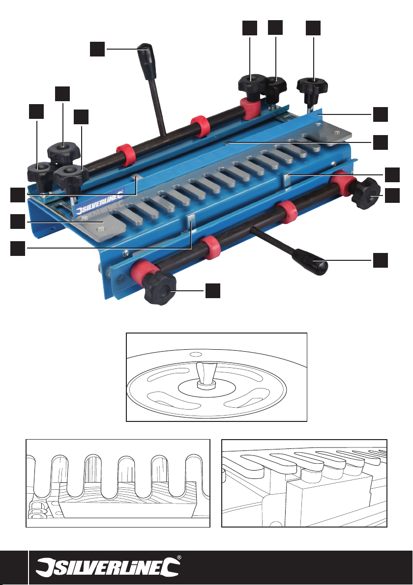
Product Familiarisation
1 Horizontal Clamping Lever
2 Horizontal Clamping Knobs
3 Template Position Knobs
4 Fence Position Knobs
5 Fence
6 Horizontal Stop Bar
7 Template
8 Vertical Stop Bar
9 Vertical Clamping Knobs
10 Vertical Clamping Lever
Unpacking and assembly
• Carefully unpack the dovetail jig, and remove all packaging materials.
Beware of sharp edges
• The Horizontal Clamping Lever (1) and the Vertical Clamping Lever (10)
are supplied loose. The levers should be securely screwed into the
threaded holes provided so that, when clamped, the horizontal lever is
behind the jig and the vertical lever is down away from the Template (7)
4

633936 Dovetail Jig 300mm
Mounting
• This dovetail jig should always be securely mounted to the front edge of
a sturdy workbench before use
• The jig should be fixed to the bench using wood screws through the four
small holes in the jig frame
• If a permanent installation is not required the jig may be mounted to a
board that can be easily clamped to a workbench. It is important the
board is long enough so the clamps do not obstruct use of the jig
Operating Instructions
WARNING: The cutter must not contact any part of the jig. Always use the
correct-sized guide bush and cutter. Incorrect sizes will make an un-usable
joint and may damage the jig.
Configuring your router
Note: These instructions are specific to the recommended router
accessories to use with this dovetail jig. Use of other accessories to create
other joints is possible but beyond the scope of this manual.
The jig is compatible with both ¼" and ½" routers including equivalent
metric sizes. The router may need an additional collet or reducer so it can
accept ¼" router bits.
1. Fit a base to your router that will allow fitment of guide bushes
2. Install a guide bush of 11.1-12mm or 7⁄16" outer diameter so that the
router can move smoothly between the slots of the ½" Template (7).
The guide bush depth must not exceed the thickness of the template
3. Fit a 12.7mm (1⁄2") dovetail 14° cutter with a ¼" shank. The dovetail
cutter height needs to be set so that the cutting blades will not contact
the template in use but the cutting blade starts cutting at the surface
of the wood. The dovetail cutter should be approximately 17mm
height from the base plate of the router. See Fig A
Preparation
This jig is suitable for the creation of dovetail joints needed for drawers,
boxes and chests. The information presented below is general guidance
only. Familiarisation with this jig over time is necessary to achieve the
desired results. Fine adjustment of some measurements is required to get
an exact fit.
The jig is used to create both the tails and pins of the dovetail joint in one
process. This is achieved by using an offset position between two clamped
pieces of wood. See fig B which shows the wood position for four tails of
the dovetail joint on the vertical wood before cutting and fig C which shows
three tails of the dovetail joints after cutting. The sides of the slots where
the tail fits into are the pins.
• Wood must be cut to the correct size, with square cut ends. Allow for the
depth of the joint when calculating wood sizes
• Use a pencil to label the wood indicating front, back, left, right, inside,
outside and any other information that might assist in cutting the wood
correctly. For example, write matching numbers on the ends of the
wood to be joined together, and note which end is for tails and which
part is pins
Important: The use of a square is recommended to ensure that correct
angles are achieved in all stages of setting up the dovetail jig. Accurate
alignment of the wood is crucial to achieving a good quality joint. Practising
with scrap material is highly recommended to develop accuracy when
using the jig.
Setting the vertical and horizontal stop bars
Note: A spanner (not supplied) is required to adjust the Horizontal Stop Bars
(6) and the Vertical Stop Bars (8).
1. Loosen the Horizontal Clamping Knobs (2) and Vertical Clamping
Knobs (9), and raise the Horizontal Clamping Lever (1) and the Vertical
Clamping Lever (10) to allow access to the stop bars adjustment nuts
easily
2. Set the left-hand Horizontal Stop Bar (6) to a position where the
Template (7) indicates a suitable place for the first dovetail joint female
slot for the size of the wood so that the dovetail joints are evenly
spaced across the wood. The left-hand Vertical Stop Bar (8) should be
set so that it is positioned 12.7mm (½") to the right of the Horizontal
Stop Bar (6). This is the offset which is approximately the width of a
finger of the template
• The initial horizontal stop bar position in relation to the template fingers
may vary slightly depending on how much border is required. The border
is the distance from the edge of the vertical wood to the first dovetail tail.
The offset between the two pieces of wood is always the thickness of a
template finger 12.7mm (1⁄2") in order to line up two equal width pieces
of wood after jointing. Once cut, the wood in Fig B will have a smaller
border than that in Fig C
• Use the right-hand side horizontal and vertical stop bars to secure and
align larger pieces of wood more centrally in the jig. The right-hand side
stop bars can also be used in preference to the left-hand side or used for
another two pieces of wood secured at the same time as the left side so
two dovetail joints can be made in one operation
• When securing two sets of wood, the left-hand or right-hand side
Horizontal Clamping Knobs (2) and Vertical Clamping Knobs (9) can
be used instead of the Horizontal Clamping Lever (1) and the Vertical
Clamping Lever (10) to allow releasing or fitting of wood to the left or
right side only without affecting the position of the wood already fitted
on the other side
• Once the stop bars are in the correct offset position lining up the two
pieces of wood exactly level when jointed, avoid adjusting the stop
bar position again. This is only possible if the same size wood is being
worked on. Alternatively, once the correct offset position has been found
between the horizontal and vertical stop bars, an offset spacer can be
made from a small piece of wood to that exact measurement. This will
enable the offset position to be set quickly and accurately even when
using different size pieces of wood
Clamping and positioning the wood
1. Pull the Horizontal Clamping Lever (1) towards the back of the jig,
loosen the two Horizontal Clamping Knobs (2) and slide the horizontal
piece of wood into the jig from the rear
2. The wood should pass underneath the fence (5) and the Template
(7). The left-hand side of the wood should be lying against the left
Horizontal Stop Bar (6) and the front of the wood should be level with
the front of the main body of the jig to allow for the vertically placed
wood to be positioned in front of it (Fig B)
3. Tighten the Horizontal Clamping Knobs (2) so the clamp is very close
to the surface of the wood. Recheck the position of the wood and pull
the horizontal clamping lever towards the front of the jig to secure the
wood
• The clamp needs to be set so that operating the clamping lever allows
the wood to be inserted and secured without additional use of the
clamping knobs
• Do not force the clamping lever if there is too much resistance when
operating. Loosen the clamping knobs to adjust it to the optimum setting
that holds the wood securely but does not put unnecessary strain on the
clamping mechanism to prevent it being damaged
4. Pull the Vertical Clamping Lever (10) up so it is in the unclamped
position and loosen the Vertical Clamping Knobs (9)
5. If the vertical piece of wood has already been cut for the joint at the
other end, make sure the wood is inserted in the correct way. Once
the dovetail joint is cut the vertical wood in the jig fits to the horizontal
wood at 180° to its cut position, as if hinged at the cut position and
rotated 180° upwards
www.silverlinetools.com
5

GB
6. Insert the vertical piece of wood from below into the front of the jig.
The wood should pass behind the front clamp assembly, and be in
contact with the vertical edge of the frame
7. Position the left side of the wood against the left-hand side Vertical
Stop Bar (8)
8. As per the horizontal clamp adjust the clamp so that the wood can be
inserted and secured simply by operating the clamping lever
9. Align the vertical wood so the height is parallel with the horizontal
wood as shown in Fig B
10.Move the vertical clamping lever to the down position to lock the
wood in place
Adjusting of the template position
To adjust the position of the Template (7) to allow for correct positioning
loosen the Template Position Knobs (3) and adjust the template position to
suit the thickness of the wood making sure the template is even on both
sides. The tips of the template should be approximately 2.5mm back from
the front edge of the vertical piece of wood. Ensure the template is kept
parallel with the jig body.
Adjusting the fence
The fence controls how deep the female dovetail slots are by limiting the
movement of the base of the router. There are no set values of distance as
this value depends on the size of the router base and the thickness of the
wood. The formula for this is:
Distance = (2 x thickness of vertical wood) + (½ width of router base)
– (cutter radius)
This is measured from the fence to the end of the fingers on the Template
(7). If you have used the recommended ½" dovetail cutter, the cutter radius
value will be 6.35mm (1⁄4")
Note: If using a router without a completely round base (possibly a router
that has 2 flat sides to its base) measure the distance from the centre of
the base to the edge closest to the centre of the base. When operating the
router remember to work to the base side you have measured to. If you set
to the widest distance of the base there is a risk of the cutter coming into
contact with the jig if you then use the side of the base closest to the cutter.
Cutting a dovetail joint
1. Ensure both the router and jig are set up using the instructions above,
including using scrap wood in the jig if this is your first dovetail joint
2. Wear any necessary personal protective equipment including a face
mask especially if there is any risk of toxic particles (for example, from
man-made composite woods)
3. Set the router to a speed that does not exceed that of the maximum
speed of the dovetail cutter
4. Place the router onto the Template (7) with the router cutter not
touching the wood but close to it in an ideal position to start cutting
5. Hold the router securely and turn on, allow the motor to reach full
speed
6. Carefully begin cutting, allowing the router guide bush to follow the
slots of the template, entering the slot on the left side and following
the curve of the slot so that the guide bush is against the right side
of the slot when leaving the slot. Do not cut into slots individually but
instead cut in one process carefully going around the shape of the
template. The end result will look like Fig C
7. While operating the router make sure the cutter does not contact any
part of the jig and do not lift the router while cutting. Once the cut
is complete, switch off the router and allow the cutter time to stop
rotating before removing carefully from the template
• Once the cut has been made, remove the wood from the jig and check
the joint. A correctly cut joint should be neither too loose nor too tight to
connect. Using a light mallet can be used to tap the joint into place if it
is a tight joint.
• If the joint is not correct or if more practising is required, saw off the ends
of the test pieces so they can be used again
Optional Accessories
Contact your Silverline stockist for a range of accessories suitable for use
with this product including;
245122 – 10 Piece Guide Bush Set in Case (including a 11.1mm (7⁄16")
guide bush)
792084 – 12 Piece ¼" Router Bit Set (including a ½" 14° dovetail cutter)
656577 – 24 Piece ¼" Router Bit Set (including a ½" 14° dovetail cutter)
Maintenance
Keep your dovetail jig clean. Do not allow dust to build up around the jig.
Clean regularly with a soft brush or vacuum, clean resin off with a suitable
solvent
6

Troubleshooting
Dovetail joint is not at a 90° angle Recheck that wood is correctly fitted and clamped
Dovetail Jig 300mm633936
Problem Solution
Dovetail joint is at an angle with the two pieces of wood not level but slightly
Where jointed the two pieces of wood are slightly stepped and not level
Splintering of the wood as the cutter leaves the workpiece
angled apart
The dovetail pins are too long or short
Dovetail joint too tight
Dovetail joint too loose
Recheck that the angle of wood to the Horizontal Stop Bars and Vertical Stop
Bars is correct using a square and the angle between the stop bars is correct
Offset of the stop bar needs adjustment
Fence position needs adjustment towards or away from the Template (7)
decrease the dovetail cutter height from the router base
increase the dovetail cutter height from the router base
Clamp another piece of wood over the vertical wood if possible to prevent
Scribe a line across the wood at the cut height to prevent splintering
splintering
More careful router operation
Cut with the grain
www.silverlinetools.com
7

F
Caractéristiques techniques
Ecart entre dents du peigne : ..................... 12,7mm (½")
Bague de copiage (non fourni) : .................. 11,1 mm (7⁄16")
Fraise queue d’aronde (non fournie) : ......... Queue de
6,35mm (¼") ; 12,7 mm (½") x 14˚
Epaisseur maximale du matériau : ............. 32 mm
Plage de largeur horizontale : ..................... de 140 à 300 mm
Plage de largeur verticale : ......................... de 150 à 275 mm
Poids : ........................................................ 9,5 kg
Consignes générales de sécurité
AVERTISSEMENT Veuillez lire l’intégralité des consignes de sécurité
et des instructions. Le non-respect de ces consignes et instructions peut
entraîner un risque de choc électrique, d’incendie et/ou se traduire par des
blessures graves.
Veuillez conserver ces instructions et consignes de sécurité pour
référence ultérieure.
Sécurité sur la zone de travail
a) Maintenir une zone de travail propre et bien éclairée. Des zones
encombrées et mal éclairées sont sources d’accidents.
b) Ne pas utiliser d’outils dans des environnements explosifs,
tels qu’à proximité de liquides, de gaz ou de poussières
inflammables.
c) Eloigner les enfants et les passants pendant l’utilisation d’un
appareil électrique. Ceux-ci peuvent provoquer une perte d’attention
et faire perdre la maîtrise de l’appareil.
Sécurité des personnes
a) Rester vigilent et faire preuve de bon sens lors de la manipulation
de l’appareil. Ne pas utiliser un appareil électrique lorsque l’on
se trouve dans un état de fatigue, ou sous l’influence de drogues,
d’alcool ou de médicaments. Un moment d’inattention pendant
l’utilisation d’un outil électrique peut se traduire par des blessures
graves.
b) Porter un équipement de protection approprié. Toujours porter
une protection oculaire. Le port de masque à poussières, chaussures
de sécurité antidérapantes, casque de sécurité et protections antibruit
adaptés aux différentes conditions de travail réduit le risque de
blessures corporelles.
c) Eviter tout démarrage accidentel ou intempestif. S’assurer que
l’interrupteur marche-arrêt soit en position d’arrêt lorsque
l’appareil n’est utilisé.
d) Enlever toute clé et tout instrument de réglage avant de mettre
l’appareil en marche. Une clé ou un instrument de réglage laissé fixé
à un élément en rotation de l’appareil électrique peut entraîner des
blessures physiques
e) Ne pas essayer d’atteindre une zone hors de portée. Se tenir
toujours en position stable permettant de conserver l’équilibre.
Cela permet de mieux contrôler l’appareil électrique dans des
situations inattendues.
f) Porter des vêtements appropriés. Ne pas porter de vêtements
amples ou des bijoux pendants. Eloigner cheveux, vêtements et
gants des pièces en mouvement. Les vêtements amples, les bijoux
pendants et cheveux longs peuvent être happés par les pièces en
rotation
g) Si l’appareil est pourvu de dispositifs destinés au raccord
d’équipements d’extraction et de récupération de la poussière/
sciure, s’assurer qu’ils soient bien fixés et utilisés correctement.
L’utilisation de ces dispositifs peut réduire les risques dus à la
poussière.
Se familiariser avec le produit
1 Levier de serrage horizontal
2 Molettes de serrage horizontal
3 Molette de positionnement du peigne
4 Molette de positionnement du guide
5 Guide
6 Butée d’arrêt horizontal
7 Peigne
8 Butée d’arrêt vertical
9 Molettes de serrage vertical
10 Levier de serrage vertical
Déballage et assemblage
• Déballez le gabarit à queue d'aronde avec précaution, en prenant soin
de retirer tout le matériau d'emballage. Faites attention aux arêtes
coupantes.
• Les leviers de serrage (1) et (10) sont livrés démontées. Ces leviers
doivent se visser solidement dans les trous filetés présents sur les barres
de serrage : de cette façon, le levier horizontal se trouve sur l’arrière de
l’appareil et le levier vertical placé en bas du peigne (7).
8

633936 Gabarit pour queues d'aronde 300 mm
Assemblage
• Avant utilisation, le gabarit doit être solidement fixé sur le bord antérieur
d'un établi robuste.
• Quatre trous de montage sont prévus sur le châssis du gabarit pour
permettre sa fixation sur l’établi à l'aide de vis à bois.
• Si vous ne voulez pas fixer définitivement le gabarit sur un établi, vous
pouvez le fixer sur une planche pour le fixer avec des serre-joints sur
l’établi. Il est important que la planche soit assez longue pour que les
serre-joints ne gênent l’utilisation du gabarit.
Instructions d’opération
ATTENTION : La fraise ne doit pas venir en contact avec aucun élément
du gabarit.
Utilisez toujours une bague de copiage et une fraise de dimensions
appropriées. Une fraise inadaptée risque de produire un assemblage nonutilisable et d'occasionner des dommages sur le gabarit.
Régler votre défonceuse
Remarque : Ces instructions sont spécifiques aux accessoires
recommandés pour l’utilisation de ce gabarit. L’utilisation d’autres
accessoires pour créer d’autres assemblages n’est pas du ressort de ce
manuel.
Le gabarit est compatible avec les défonceuses 1⁄4" et 1⁄2" y compris avec
les tailles métriques équivalentes. La défonceuse peut nécessiter une
pince de serrage supplémentaire ou une bague de réduction pour utiliser
des fraises 1⁄4".
1. Placez une embase sur votre défonceuse pour installer les bagues
de copiage.
2. Installez la bague de copiage de diamètre extérieure de 11,1 mm
(7⁄16") pour que la défonceuse puisse se déplacer facilement entre les
espaces du peigne 1⁄2" (7). La profondeur de la bague de copiage ne
doit pas être supérieure à l’épaisseur du peigne.
3. Installez la fraise à queue d’aronde de 12,7 mm (½") x 14˚ à
emmanchement 1⁄4". Le réglage de la hauteur de cette fraise doit se
faire de sorte que les tranchants ne rentrent pas en contact avec le
peigne, mais qu’ils puissent commencer à couper la surface du bois.
La fraise à queue d’aronde doit être approximativement à 17 mm de
l’embase de la défonceuse. Voir Fig.A.
Préparation
Ce gabarit est conçu pour la réalisation d’assemblage en queue d’aronde
pour des tiroirs, caisses et coffres. Les informations données ci-dessous
ne sont que des instructions générales. Se familiariser et acquérir de
l’expérience avec ce produit est nécessaire pour obtenir le résultat voulu.
Le réglage fin de certaines mesures est primordial pour un assemblage
parfait.
Ce gabarit permet de réaliser le tenon et la rainure en une seule opération.
Ceci s’effectue en utilisant une position décalée entre deux pièces de bois
jointes. La Fig. B montre la position du bois pour la réalisation des tenons
avant la coupe, et la Fig. C montre les trois tenons après la coupe, ainsi
qu’une des rainures se trouvant sur la pièce de bois horizontale.
• Les pièces de bois à usiner doivent avoir été préalablement coupées à la
taille finale souhaitée, avec des chants à l’équerre. Tenez compte de la
profondeur de l’assemblage lors du calcul des dimensions des pièces.
• Utilisez un crayon pour indiquer l’avant, l’arrière, côté gauche et droit,
intérieur et extérieur de la pièce pour effectuer une coupe du bois
précise. Utilisez par exemple des numéros sur les extrémités du bois
à assembler ensemble, pour savoir quel tenon s’assemble sur quelle
rainure.
Important : L’utilisation d’une équerre peut être utile pour obtenir les
angles corrects, mais aussi pour toutes les étapes de configuration de
l’appareil. Les alignements corrects des pièces de bois sont primordiaux
pour un assemblage parfait. Il est recommandé de s’entrainer sur des
morceaux de chute afin d’utiliser cet outil avec précision.
Régler les butées d’arrêt vertical et horizontal
Remarque : Une clé (non fournie) est requise pour régler les butées d’arrêt
horizontal (6) et les butées d’arrêt vertical (8)
1. Desserrez les molettes de serrage horizontal (2) et vertical (9), et
levez le levier de serrage horizontal et vertical (1 et 10) pour accéder
facilement aux écrous de réglages des butées d’arrêt.
2. Placez la butée d’arrêt horizontal gauche de sorte que le peigne (7)
puisse permettre de réaliser une première rainure convenablement
placé sur la pièce et ainsi obtenir un assemblage bien centré et
espacé sur la longueur de la pièce. La butée d’arrêt verticale gauche
(8) devrait être placée à 12,7 mm (1⁄2") de la butée d’arrêt horizontal(6).
Ceci est le décalage, qui est approximativement la largeur des dents
du peigne.
• Le positionnement initial de la butée d’arrêt horizontale par rapport aux
dents du peigne peut légèrement varier selon la longueur de bordure. La
bordure est la distance du bord vertical du bois à la première rainure. Le
décalage entre les deux pièces de bois est toujours la largeur d’une dent
du peigne (12,7 mm) de façon à aligner les deux largeurs des pièces de
bois entre-elles après l’assemblage. Une fois la coupe réalisée, la pièce
de bois de la Fig.B a une bordure plus petite que celle de la Fig.C.
• Utilisez les butées d’arrêt droite, vertical et horizontal, pour aligner
et centrer les plus grandes pièces de bois avec le gabarit. Les butées
droites peuvent être également, selon votre commodité, utilisée à la
place des gauches. Ou être utilisées en même temps si vous souhaitez
faire deux assemblages en une seule fois.
• Si vous effectuez deux assemblages en même temps, les molettes de
serrage vertical et horizontal (2 et 9) peuvent être utilisées à la place des
leviers de serrage (1 et 10 ) pour relâcher ou fixer une pièce de bois sans
avoir à modifier la position des pièces de bois du second assemblage.
• Une fois les butées d’arrêt en place avec le correct décalage, avec les
pièces de bois de l’assemblage de niveau, évitez de les re-régler. Ceci
est seulement possible si les pièces de bois sont de même dimension.
Autrement, une fois le décalage paramétré, vous pouvez fabriquer
une entretoise en bois à la dimension exacte du décalage. Ceci vous
permettra de régler le gabarit rapidement et précisément lors des
prochaines utilisations même avec des pièces de bois de taille différente.
Fixer et positionner une pièce de bois.
1. Tirez le levier de serrage horizontal (1) vers l’arrière du gabarit,
desserrez les deux molettes de serrage (2), et faites glisser la pièce de
bois horizontale depuis l’arrière du gabarit.
2. La pièce de bois doit passer sous le guide (5) et sous le peigne (7). Le
côté gauche de la pièce de bois doit être en contact contre la butée
d’arrêt horizontal gauche (6), et l’avant de la pièce de bois doit être
de niveau avec le côté avant du gabarit, pour être par la suite, être de
niveau avec la pièce de bois verticale.
3. Resserrez les molettes de serrage horizontal (2) de sorte que la presse
soit proche de la surface du bois. Revérifiez la position du bois et tirez
le levier de serrage horizontal vers l’avant du gabarit pour maintenir le
bois en place.
• Le serrage doit être réglé de sorte que lorsque vous actionnez le levier de
serrage, vous puissiez insérer et fixer la pièce de bois sans avoir à utiliser
les molettes de serrages.
• Ne forcez pas sur le levier de serrage s’il y a trop de résistance lors de
son utilisation. Desserrez les molettes de serrage de façon à trouver
le réglage parfait permettant d’activer le levier de serrage sans avoir à
forcer dessus (et risquer d’endommager le système), tout en maintenant
la pièce de bois bien fixée.
4. Soulevez le levier de serrage vertical (10) pour le mettre en position
relâchée, et desserrez les molettes de serrage vertical (9).
5. Si la pièce de bois verticale a déjà été coupée pour l’assemblage
sur l’autre extrémité, soyez bien sûr d’insérer la pièce de bois dans
le bon sens. Une fois la coupe effectuée, la pièce verticale s’aligne
parfaitement avec la pièce horizontale si mises bout à bout.
6. Insérez la pièce de bois par le bas sur l’avant du gabarit. La pièce de
bois doit donc se trouver entre le tampon du levier de serrage et le
bord vertical du gabarit.
www.silverlinetools.com
9

F
7. Positionnez le bord gauche de la pièce de bois contre la butée d’arrêt
vertical (8).
8. Tout comme le serrage horizontal, faites un réglage du serrage de
sorte que la pièce de bois puisse s’insérer et être fixée en utilisant
simplement le levier de serrage.
9. Alignez le bord de la pièce verticale avec celui de la pièce horizontale,
comme indiqué sur la Fig.B
10.Abaissez le levier de serrage vertical pour maintenir la pièce de bois.
Régler la position du peigne
Pour régler la position du peigne (7), desserrez les molettes de
positionnement du peigne. Positionnez le peigne en fonction de l’épaisseur
du bois et assurez-vous qu’il soit bien centré par rapport aux extrémités
de la pièce de bois. Les dents du peigne doivent être approximativement à
2,5 mm du bord de la pièce verticale. Assurez-vous que le peigne soit bien
parallèle par rapport au châssis du gabarit.
Régler le guide
Le guide contrôle la profondeur des rainures en stoppant le mouvement
de l ‘embase de la défonceuse. Pour connaitre la distance à laquelle le
guide doit être placé, il faut prendre en compte la taille de la défonceuse et
l’épaisseur du bois. Cette distance se calcule de la façon suivante :
Distance = (épaisseur du bois vertical x 2) + (largeur de l’embase de
la défonceuse x 0,5 )- (rayon de la fraise)
Cette distance est celle se trouvant entre le guide et l’extrémité des dents
du peigne (7). Si vous utilisez la fraise ½" recommandée pour queue
d’aronde, le rayon de la fraise est de 6,35 mm
Remarque : Si vous utilisez une défonceuse avec une embase qui n’est
pas totalement ronde (possédant deux faces droites), mesurez la distance
avec le côté le plus proche du centre de la défonceuse. En utilisant la
défonceuse, rappelez-vous de travailler avec le côté de l’embase avec
lequel vous avez effectué la mesure. Si vous mesurez la distance avec le
côté le plus éloigné de l’embase, il y a un risque que la fraise vienne en
contact avec le gabarit si par après, vous utilisez le côté le plus proche
du centre.
Effectuer la coupe pour un assemblage à queue d’aronde
1. Assurez-vous de régler la défonceuse et le gabarit comme indiqué
dans ci-dessus. Pour une première utilisation il est recommandé
d’effectuer un test sur un morceau de chute.
2. Portez les équipements personnels de sécurité, ainsi qu’un masque
respiratoire en cas de présence de particules toxiques (par exemple
dans les bois composites)
3. Régler la vitesse de la défonceuse pour qu’elle ne dépasse pas la
vitesse maximale de la fraise
4. Placez la défonceuse sur le peigne (7) avec la fraise ne touchant pas le
bois, mais assez proche pour bien commencer la coupe.
5. Maintenez bien la défonceuse, mettez en marche, et attendez que le
moteur atteigne sa pleine vitesse
6. Commencez à couper avec précaution, en faisant suivre la bague
de copiage entre les dents du peigne en allant de la gauche vers la
droite. Réalisez la coupe en une seule passe et sans pause. Le résultat
obtenu ressemble à celui de la Fig. C
7. En utilisant la défonceuse, vérifiez bien que la fraise ne rentre pas en
contact avec le gabarit, et ne soulevez pas la défonceuse pendant la
coupe. Une fois la coupe terminée, éteignez la défonceuse et attendez
l’arrêt total de la fraise avant de la retirer.
• Une fois la coupe terminée, retirez la pièce de bois du gabarit et vérifiez
l’assemblage. Un assemblage correct ne sera ni trop lâche, ni trop serré.
Utilisez un maillet si l’assemblage est trop serré.
• Si l’assemblage n’est pas correct ou si vous vous entrainez, sciez les
extrémités des pièces pour qu’elles puissent être réutilisées de nouveau.
Accessoires optionnels
Contactez votre revendeur Silverline pour une grande variété d’accessoires
compatible avec ce produit, tels que :
245122 - Coffret de 10 bagues de copiage pour défonceuse (comprenant la
bague de copiage 11,1 mm)
792084 - Coffret de 12 fraises à défoncer carbure de tungstène 1⁄4"
(comprenant la fraise 1⁄4" pour queue d’aronde)
656577 – Coffret de 24 fraises à défoncer TCT 1⁄4"
Entretien
Gardez votre gabarit toujours propre. Ne laissez pas la poussière
s’accumuler sur le gabarit. Nettoyez régulièrement avec une brosse souple
ou avec un aspirateur, et enlevez la résine avec un solvant adéquat.
10

633936 Gabarit pour queues d'aronde 300 mm
En cas de problème
Problème Solution
L’assemblage n’est pas à 90° Vérifiez comment le bois est positionné et serré
Le joint est légèrement incliné Vérifiez l’angle d’inclinaison de la pièce de bois et que les leviers horizontal et
Les deux pièces de bois ne sont pas alignées
Les tenons sont trop courts ou trop longs
L’assemblage est trop serré
L’assemblage est trop lâche
Si possible, fixez une autre pièce de bois sur le bois vertical
Le bois éclate lorsque la fraise ressort
Faites une entaille le long de la pièce à la hauteur de la fraise
vertical soient bien réglés
Réglez la butée d’arrêt horizontal
Replacez le peigne correctement
Réduisez la hauteur de la fraise
Augmentez la hauteur de la fraise
Maniez la défonceuse avec plus de précaution
Coupez dans le sens du bois
www.silverlinetools.com
11

D
Spezifikation
Schablone: ................................................. ½ Zoll (12,7 mm)
Führungshülse
(nicht im Lieferumfang enthalten): ..............7⁄16 Zoll (11,1 mm)
Fräser (nicht im Lieferumfang enthalten): ... ¼ Zoll Schaft
(6,35 mm): ½ Zoll (12,7 mm) x 14˚ Schwalbenschwanz
Maximale Materialstärke: ........................... 32 mm
Horizontale Breite: ...................................... 140 – 300 mm
Vertikale Breite: .......................................... 150 – 275 mm
Gewicht: ..................................................... 9,5 kg
Sicherheitshinweise
WARNUNG! Lesen Sie alle Sicherheitshinweise und Anweisungen.
Versäumnisse bei der Einhaltung der Sicherheitshinweise und Anweisungen
können elektrischen Schlag, Brand und/oder schwere Verletzungen
verursachen.
Bewahren Sie alle Sicherheitshinweise und Anweisungen für die
Zukunft auf.
Arbeitsplatzsicherheit
a) Halten Sie Ihren Arbeitsbereich sauber und gut beleuchtet.
Unordnung oder unbeleuchtete Arbeitsbereiche können zu Unfällen
führen.
b) Arbeiten Sie mit dem Werkzeug nicht in explosionsgefährdeter
Umgebung, in der sich brennbare Flüssigkeiten, Gase oder Stäube
befinden.
c) Halten Sie Kinder und andere Personen während der Benutzung
des Werkzeugs fern. Bei Ablenkung können Sie die Kontrolle über
das Gerät verlieren.
Sicherheit von Personen
a) Seien Sie aufmerksam, achten Sie darauf, was Sie tun, und gehen
Sie mit Vernunft an die Arbeit mit einem Werkzeug. Benutzen
Sie kein Werkzeug, wenn Sie müde sind oder unter dem Einfluss
von Drogen, Alkohol oder Medikamenten stehen. Ein Moment der
Unachtsamkeit beim Gebrauch des Werkzeuges kann zu ernsthaften
Verletzungen führen.
b) Tragen Sie persönliche Schutzausrüstung und immer eine
Schutzbrille. Das Tragen persönlicher Schutzausrüstung, wie
Staubmaske, rutschfeste Sicherheitsschuhe, Schutzhelm oder
Gehörschutz, je nach Art und Einsatz des Werkzeuges, verringert das
Risiko von Verletzungen.
c) Vermeiden Sie eine unbeabsichtigte Inbetriebnahme.
Vergewissern Sie sich, dass das Werkzeug ausgeschaltet ist,
wenn es nicht verwendet wird, und dass andere evtl. vorhandene
Einschaltsperren aktiviert sind.
d) Entfernen Sie Einstellwerkzeuge oder Schraubenschlüssel, bevor
Sie das Werkzeug einschalte. Ein Werkzeug oder Schlüssel, der sich
in einem drehenden Geräteteil befindet, kann zu Verletzungen führen.
e) Vermeiden Sie eine unnatürliche Körperhaltung. Sorgen Sie für
einen sicheren Stand und halten Sie jederzeit das Gleichgewicht.
Auf diese Weise lässt sich das Elektrowerkzeug in unerwarteten
Situationen besser kontrollieren.
f) Tragen Sie geeignete Kleidung. Tragen Sie keine weite Kleidung
oder Schmuck. Halten Sie Haare, Kleidung und Handschuhe fern
von sich bewegenden Teilen. Lockere Kleidung, Schmuck oder
lange Haare können von sich bewegenden Teilen erfasst werden.
g) Wenn Staubabsaug- und -auffangeinrichtungen montiert werden
können, vergewissern Sie sich, dass diese angeschlossen sind
und richtig verwendet werden. Verwendung einer Staubabsaugung
kann Gefährdungen durch Staub verringern.
Geräteübersicht
1 Horizontaler Spannhebel
2 Horizontale Feststellschrauben
3 Schablonenpositionsschrauben
4 Anschlagpositionsschrauben
5 Anschlag
6 Horizontale Anschlagsleiste
7 Schablone
8 Vertikale Anschlagsleiste
9 Vertikale Feststellschrauben
10 Vertikaler Spannhebel
Auspacken und Zusammenbau
• Das Schwalbenschwanzfräsgerät vorsichtig auspacken und alle
Verpackungsmaterialien entfernen. Vorsicht bei scharfen Kanten!
• Der horizontale Spannhebel (1) und der vertikale Spannhebel (10)
werden lose geliefert. Die Hebel müssen sicher in die Gewindelöcher
eingeschraubt werden, damit sich beim Spannen der horizontale Hebel
hinter dem Fräsgerät und der vertikale Hebel nach unten weg von der
Schablone (7) befindet.
12

633936 Zinkenfräsgerät, 300 mm
Montage
• Dieses Schwalbenschwanz Fräsgerät sollte vor Gebrauch immer sicher
an der Vorderkante einer festen Werkbank befestigt sein.
• Das Fräsgerät sollte mittels Holzschrauben in den vier kleinen Löchern
des Geräterahmens an der Werkbank befestigt sein.
• Falls eine permanente Installation nicht erforderlich ist, kann das
Fräsgerät an einem Brett montiert werden, damit dieses leicht in eine
Werkbank geklemmt werden kann. Achten Sie darauf, dass das Brett
lang genug ist, damit die Klemmen nicht die Benutzung des Fräsgeräts
behindern.
Bedienungsanleitung
ACHTUNG! Die Schneide darf nicht mit irgendeinem Teil des Geräts in
Berührung kommen. Stets die passende Führungshülse und Schneide
benutzen. Falsche Größen produzieren unbrauchbare Fräsverbindungen und
können das Gerät beschädigen.
Einstellung der Oberfräse
Hinweis: Diese Anweisungen sind speziell für das Zubehör der
empfohlenen Oberfräse, das mit dieser Schwalbenschwanzfräse benutzt
werden sollte. Die Anwendung anderen Zubehörs zur Herstellung anderer
Fräsverbindungen ist möglich, geht aber über den Rahmen dieses
Handbuches hinaus.
Das Fräsgerät ist kompatibel mit ¼-Zoll- und ½-Zoll-Oberfräsen inklusive
der entsprechenden metrischen Größe. Die Oberfräse könnte eine weitere
Spannzange benötigen, um ¼-Zoll-Fräser zu akzeptieren.
1. Befestigen Sie eine Grundplatte an Ihre Oberfräse, die einen Einbau
der Führungshülsen ermöglicht.
2. Montieren Sie eine Führungshülse mit einem Außendurchmesser von
11,1 - 12 mm, bzw. 7⁄16 Zoll, damit die Oberfräse glatt zwischen den
Schlitzen der 0,5 mm (½ Zoll) Schablone (7) laufen kann. Die Tiefe der
Führungshülse darf nicht die Dichte der Schablone überschreiten.
3. Einen 12,7 mm (1⁄2 Zoll) 14°-Schwalbenschwanz-Fräser in einer
¼-Zoll-Spannzange montieren. Die Höhe der Schwalbenschwanz
Schneide muss so eingestellt werden, dass die Schneidmesser nicht
in Berührung mit der benutzten Schablone geraten, sondern so, dass
das Schneidmesser auf der Oberfläche des Holzstücks schneiden.
Die Schwalbenschwanz Schneide sollte ca. 17 mm hoch von der
Grundplatte der Oberfräse eingestellt sein. Siehe Abb. A.
Vorbereitung
Dieses Fräsgerät eignet sich zur Herstellung von
Schwalbenschwanzverbindungen, die für Schubladen, Kästen und Truhen
erforderlich sind. Die u. g. Informationen dienen nur als allgemeiner
Ratschlag. Es ist notwendig sich mit diesem Fräsgerät über einen Zeitraum
hinweg vertraut zu machen, um die gewünschten Ergebnisse zu erzielen.
Feineinstellungen mancher Maße sind erforderlich, um eine exakte
Einpassung zu erzielen.
Das Fräsgerät wird benutzt, um die Enden und Stifte der
Schwalbenschwanzverbindung in einem Vorgang herzustellen. Das
wird durch Nutzung einer Ausgleichsposition zwischen den beiden
eingespannten Holzstücken erreicht. Siehe Abb. B, welche die Holzposition
für vier Enden der Schwalbenschwanzverbindung auf dem vertikalen
Holzstück vor dem Schneiden zeigt, und Abb. C, welche die drei Enden der
Schwalbenschwanzverbindung nach dem Schneiden zeigt. Die Seiten der
Schlitze, wo die Enden eingepasst sind, sind die Stifte.
• Das Holz muss auf die richtige Größe zugeschnitten werden mit
quadratisch zugeschnittenen Enden. Berücksichtigen Sie die Tiefe der
Verbindung bei der Berechnung der Holzgrößen.
• Nehmen Sie einen Bleistift, um das Holzstück auf der Vorder- und
Rückseite, links, rechts, auf der Innen- und Außenseite, und um alle
weiteren Informationen zu markieren, die dabei helfen könnten, das
Holzstück korrekt zuzuschneiden. Schreiben Sie z. B. die passenden
Zahlen auf die Enden des Holzstückes, die miteinander verbunden
werden sollen, und beachten Sie, welches Ende für die Enden und
welches für die Stifte ist.
Wichtiger Hinweis: Es wird empfohlen ein Quadrat zu benutzen, damit
gewährleistet wird, dass die korrekten Winkel in allen Stadien der
Einstellung der Schwalbenschwanzfräse eingehalten werden. Eine präzise
Ausrichtung des Holzstückes ist notwendig, um eine qualitativ gute
Verbindung zu erzielen. Das vorherige Üben mit einem Probeholzstück wird
äußerst empfohlen, um eine Genauigkeit bei der Benutzung dieser Fräse
entwickeln zu können.
Einstellung der vertikalen und horizontalen Anschlagleisten
Hinweis: Ein Schraubenschlüssel (nicht mitgeliefert) ist erforderlich, um
die horizontalen Anschlagleisten (6) und die vertikalen Anschlagleisten (8)
einzustellen.
1. Die horizontalen Feststellschrauben (2) und vertikalen
Feststellschrauben (9) lockern, und den horizontalen Spannhebel (1)
und den vertikalen Spannhebel (10) anheben, für einen leichteren
Zugang zu den Einstellmuttern der Anschlagleisten.
2. Die linke, horizontale Anschlagleiste (6) in der Position einstellen,
in der die Schablone (7) einen geeigneten Platz für die erste
Schwalbenschwanzverbindungsbuchse für diese Holzgröße anzeigt,
damit die Schwalbenschwanzverbindungen gleichmäßig über das
Holzstück verteilt werden. Die linke, vertikale Anschlagleiste (8) sollte
so eingestellt werden, damit sie 12,7 mm (½ Zoll) rechts von der
horizontalen Anschlagleiste (6) positioniert ist. Dies ist der Ausgleich,
der ungefähr eine Fingerbreite der Schablone beträgt.
• Die erste horizontale Anschlagsleistenposition in Bezug auf die
Schablonenfinger kann leicht variieren, je nachdem wie viel Rand
erforderlich ist. Der Rand ist die Strecke zwischen der Kante des
vertikalen Holzstückes bis zum ersten Schwalbenschwanz. Der
Ausgleich zwischen den beiden Holzstücken ist immer die Dichte eines
Schablonenfingers 12,7 mm (1⁄2 Zoll), um zwei gleich breite Holzteile nach
dem Ausfugen miteinander auszurichten. Nachdem es gefräst wurde,
wird das Holzstück in Abb. B einen schmaleren Rand als in Abb. C haben.
• Die rechten, horizontalen und vertikalen Anschlagleisten benutzen, um
größere Holzstücke zentraler im Fräsgerät zu sichern und auszurichten.
Die rechten Anschlagleisten können auch statt der Linken benutzt
werden oder sie können für zwei weitere Holzstücke benutzt werden,
um sie zur gleichen Zeit wie die Linken zu sichern, damit zwei
Schwalbenschwanzverbindungen in einem Vorgang erstellt werden
können.
• Beim Sichern von zwei Paar Holzstücken können die linken oder
die rechten horizontalen Feststellschrauben (2) und die vertikalen
Feststellschrauben (9) benutzt werden, statt des horizontalen
Spannhebels (1) und des vertikalen Spannhebels (10), um die Freigabe,
bzw. Einpassung des Holzstückes nur an die linke oder rechte Seite zu
ermöglichen ohne die Position des Holzstückes zu beeinträchtigen, das
bereits auf der anderen Seite eingepasst ist.
• Nachdem die Anschlagleisten in der korrekten Ausgleichposition sind und
die beiden Holzstücke exakt gerade beim Ausfugen ausgerichtet sind,
eine erneute Einstellung der Anschlagleistenposition vermeiden. Das ist
nur möglich, wenn die gleiche Holzgröße benutzt wird. Alternativ kann,
nachdem die korrekte Ausgleichsposition zwischen der horizontalen und
der vertikalen Anschlagleiste gefunden wurde, ein Ausgleichsstandhalter
aus einem kleineren Stück Holz für dieses exakte Maß hergestellt
werden. Das ermöglicht die schnelle und präzise Einstellung der
Ausgleichsposition, wenn verschieden große Holzstücke benutzt werden.
www.silverlinetools.com
13

D
Festklemmen und Positionierung des Holzstückes
1. Den horizontalen Spannhebel (1) zur Rückseite des Fräsgeräts ziehen,
die horizontalen Feststellschrauben (2) lockern und das horizontale
Holzstück von hinten in das Fräsgerät einschieben.
2. Das Holzstück sollte unter dem Anschlag (5) und der Schablone (7)
durchlaufen. Die linke Seite des Holzstückes sollte bündig gegen die
linke Anschlagleiste (6) liegen und die Vorderseite des Holzstückes
sollte gerade mit der Vorderseite des Fräsgeräts liegen, damit das
vertikal platzierte Holzstück davor positioniert werden kann (Abb. B).
3. Die horizontalen Feststellschrauben (2) festziehen, damit die Klemme
sehr dicht an der Oberfläche des Holzstückes liegt. Erneut die Position
des Holzstückes überprüfen und den horizontalen Spannhebel zur
Vorderseite des Fräsgeräts ziehen, um das Holzstück zu sichern.
• Die Klemme muss eingestellt werden, damit die Bedienung des
Spannhebels es ermöglicht, dass das Holzstück eingeschoben und
gesichert werden kann ohne weiter die Feststellschrauben zu benutzen.
• Den Spannhebel nicht forcieren, wenn zu viel Widerstand bei der
Bedienung besteht. Die Feststellschrauben lockern, um sie zur
optimalen Einstellung einzustellen, die das Holzstück sicher fixiert, aber
nicht unnötigerweise Kraft auf den Klemm-Mechanismus ausübt, um
eventuelle Schäden hieran zu vermeiden.
4. Den vertikalen Spannhebel (10) nach oben ziehen, damit er in der
ungespannten Position ist und die vertikalen Feststellschrauben (9)
lockern.
5. Falls das vertikale Holzstück bereits für die Verbindung am
anderen Ende geschnitten wurde, bitte dabei beachten, dass das
Holzstück dann auf die korrekte Art eingeführt wird. Nachdem die
Schwalbenschwanzverbindung gefräst wurde, passt das vertikale
Holzstück bei 180° in seine Schnittposition, als ob es an der
Schnittposition aufgehängt und 180° nach oben gedreht ist.
6. Das vertikale Holzstück von unten in die Vorderseite des Fräsgeräts
einschieben. Das Holzstück sollte hinter dem vorderen Spannaufbau
vorbeilaufen und in Kontakt mit der vertikalen Kante des Rahmens
liegen.
7. Die linke Seite des Holzstückes gegen die linke Seite der vertikalen
Anschlagleiste (8) positionieren.
8. Wie bei der horizontalen Spanne die Klemme so einstellen, dass das
Holzstück einfach durch Bedienung des Spannhebels eingeführt und
gesichert werden kann.
9. Das vertikale Holzstück so ausrichten, dass die Höhe parallel mit dem
horizontalen Holzstück verläuft wie in Abb. B gezeigt.
10.Den vertikalen Spannhebel in die untere Position bewegen, um das
Holzstück festzuklemmen.
Einstellung der Schablonenposition
Zur Einstellung der Position der Schablone (7), um eine korrekte
Positionierung zu ermöglichen, die Schablonenpositionsschrauben
(3) lockern und die Schablonenposition auf die geeignete Dichte des
Holzstückes einstellen, dabei darauf achten, dass die Schablone auf beiden
Seiten gleich ist. Die Spitzen der Schablone sollten ca. 2,5 mm hinter der
Vorderkante des vertikalen Holzstückes liegen. Darauf achten, dass die
Schablone parallel mit dem Fräsgerät liegt.
Einstellung des Anschlags
Der Anschlag kontrolliert wie tief die Schwalbenschwanzbuchsen sind,
indem die Bewegung der Grundplatte der Oberfräse einschränkt wird.
Es gibt keine Sollwerte für die Distanz, da dieser Wert von der Größe der
Grundplatte der Oberfräse und der Dichte des Holzes abhängig ist. Die
Formel hierfür ist:
Distanz = (2 x Dichte des vertikalen Holzstücks) + (½ Breite der
Grundplatte der Oberfräse) – (Schneide Radius)
Dies wird gemessen vom Anschlag bis zum Ende der Finger auf der
Schablone (7). Falls Sie die empfohlene ½-Zoll-Schwalbenschwanzschneide
benutzt haben, wird der Schneideradiuswert 6,35 mm (1⁄4 Zoll) betragen.
Hinweis: Wenn eine Oberfräse ohne eine komplett runde Grundplatte (evtl.
eine Oberfräse, die 2 flache Seiten an ihrer Grundplatte hat) benutzt wird,
die Distanz von der Mitte der Grundplatte bis zur Kante am dichtesten zur
Mitte der Grundplatte messen. Bei Bedienung der Oberfräse beachten zur
Grundseite, die bemessen wurde, zu arbeiten. Falls sie auf die breiteste
Distanz der Grundplatte eingestellt wurde, besteht das Risiko, dass die
Schneide mit dem Fräsgerät in Berührung kommt, wenn man dann die
Seite der Grundplatte am dichtesten zur Schneide benutzt.
Fräsen einer Schwalbenschwanzverbindung
1. Gewährleisten, dass die Oberfräse und das Fräsgerät gemäß der
o.g. Anweisungen eingestellt wurden, inklusive zur Benutzung
von Probeholzstücken im Fräsgerät, falls Sie zum ersten Mal eine
Schwalbenschwanzverbindung herstellen.
2. Alle erforderlichen Schutzausrüstungen tragen, inklusive einer
Gesichtsmaske, insbesondere, wenn ein Risiko an giftigen Partikeln
besteht (z. B. von künstlichen Verbundhölzern).
3. Die Oberfräse auf eine Geschwindigkeit einstellen, welche nicht
die der maximalen Geschwindigkeit der Schwalbenschwanzfräse
überschreitet.
4. Die Oberfräse auf die Schablone (7) führen, wobei die Schneide der
Oberfräse nicht das Holz berühren darf, aber dicht am Holzstück dran
liegt in einer idealen Position, um mit dem Fräsen zu beginnen.
5. Die Oberfräse sicher halten und einschalten, warten bis der Motor die
volle Geschwindigkeit erreicht hat.
6. Vorsichtig mit dem Fräsen beginnen, der Führungshülse der Oberfräse
ermöglichen, den Schlitzen entlang der Schablone zu folgen, auf der
linken Seite in die Schlitze einfräsen und der Kurve des Schlitzes
folgen, damit die Führungshülse gegen die rechte Seite des Schlitzes
liegt, wenn dieser Schlitz verlassen wird. Nicht einzeln in die Schlitze
fräsen, sondern stattdessen in einem Vorgang vorsichtig um die Form
der Schablone herum fräsen. Das Endergebnis wird wie in Abb. C
aussehen.
7. Bei Bedienung der Oberfräse darauf achten, dass die Schneide nicht
mit irgendeinem Teil des Fräsgeräts in Berührung kommt und die
Oberfräse nicht beim Fräsen anheben. Nachdem der Schnitt beendet
ist, die Oberfräse ausschalten und warten bis die Schneide sich nicht
mehr dreht, ehe das Holzstück vorsichtig von der Schablone entfernt
wird.
• Nachdem der Schnitt gemacht wurde, das Holzstück von der Fräse
entfernen und die Verbindung prüfen. Eine korrekt gefräste Verbindung
sollte weder zu lose noch zu fest zu verbinden sein. Ein leichter
Gummihammer kann benutzt werden um die Verbindung zurecht zu
hämmern bis sie eine dichte Verbindung ergibt.
• Falls die Verbindung nicht richtig ist oder wenn mehr Übung erforderlich
ist, die Enden der Teststücke absägen, damit die Holzstücke erneut
benutzt werden können.
Optionales Zubehör
Wenden Sie sich an Ihren Silverline Händler für eine Auswahl an Zubehör,
das für dieses Produkt geeignet ist, inklusive:
245122 – 10-tlg. Führungshülsenset im Aufbewahrungskasten (inklusive
einer 11,1-mm- (7⁄16-Zoll-) Führungshülse)
792084 – 12-teiliges ¼-Zoll-Fräserset (inklusive eines ½-Zoll-14°Schwalbenschwanz-Fräsers)
656577 -24-teiliges ¼-Zoll-Fräserset (inklusive eines ½-Zoll-14°Schwalbenschwanz-Fräsers)
Wartung
Das Schwalbenschwanzfräsgerät sauber halten. Darauf achten, dass
sich kein Staub rund um das Fräsgerät anhäuft. Regelmäßig mit einer
weichen Bürste oder dem Staubsauger reinigen, Harz mit einem geeigneten
Lösemittel entfernen.
14

633936 Zinkenfräsgerät, 300 mm
Fehlersuche
Problem Lösung
Die Schwalbenschwanzverbindung ist nicht in einem 90° Winkel.
Erneut überprüfen, dass das Holzstück korrekt eingepasst und festgeklemmt
wurde.
Die Schwalbenschwanzverbindung ist in einem Winkel zu den beiden
Holzstücken, nicht gerade aber leicht angewinkelt voneinander.
Wo sie miteinander verbunden sind, sind die beiden Holzstücke leicht abgestuft
Die Schwalbenschwanzstifte sind zu lang oder zu kurz.
Die Schwalbenschwanzverbindung ist zu fest.
Die Schwalbenschwanzverbindung ist zu lose.
Das Holz splittert, wenn die Schneide es verlässt.
und nicht gerade.
Erneut überprüfen, dass der Winkel des Holzstücks zu den horizontalen
Anschlagleisten und den vertikalen Anschlagleisten korrekt ist durch
Anwendung eines Quadrats und überprüfen, dass der Winkel zwischen den
Die Ausrichtung der Anschlagleiste muss eingestellt werden.
Die Anschlagposition muss zur Schablone (7) in oder von ihr weg eingestellt
Die Höhe der Schwalbenschwanz Schneide von der Grundplatte der Oberfräse
Die Höhe der Schwalbenschwanz Schneide von der Grundplatte der Oberfräse
Ein weiteres Holzstück über das vertikale Holzstück klemmen, falls möglich, um
Eine Linie quer über das Holz in der Schnitthöhe zeichnen, um eine Splitterung
Anschlagleisten korrekt ist.
werden.
senken.
erhöhen.
die Splitterung zu vermeiden.
Die Oberfräse vorsichtiger bedienen.
zu vermeiden.
Den Holzfaserverlauf entlang fräsen.
www.silverlinetools.com
15

ESP
Características técnicas
Paso del peine: ........................................... 12,7 mm (½")
Casquillo copiador (no incluido): ................. 11,1 mm (7⁄16")
Fresa (no incluida): ..................................... Vástago 6,35 mm
(¼") - 12,7 mm (½") x 14˚ cola de milano
Grosor máximo del material: ...................... 32 mm
Intervalo de anchura horizontal: ................. 140 – 300 mm
Intervalo de anchura vertical: ..................... 150 – 275 mm
Peso: .......................................................... 9,5 kg
Instrucciones generales de
seguridad
ADVERTENCIA: Lea todas las advertencias de seguridad e
instrucciones. No respetar estas advertencias e instrucciones puede
causar descargas eléctricas, incendios y/o lesiones graves.
Conserve estas instrucciones de seguridad para futuras referencias.
Seguridad en el área de trabajo
a) Mantenga el área de trabajo limpia y bien iluminada. Las áreas
desordenadas y oscuras invitan a que se produzcan accidentes.
b) No utilice herramientas eléctricas en atmósferas explosivas,
como por ejemplo en presencia de líquidos, gases o polvos
inflamables.
c) Mantenga alejados a los niños y a las personas que se
encuentren a su alrededor mientras esté trabajando con una
herramienta eléctrica. Las distracciones pueden hacerle perder el
control de la herramienta.
Seguridad personal
a) Manténgase alerta, fíjese en lo que está haciendo y use el sentido
común cuando esté utilizando una herramienta eléctrica. No
use una herramienta eléctrica si se encuentra cansado o bajo la
influencia de drogas, alcohol o medicamentos. Un momento de
distracción mientras esté utilizando una herramienta eléctrica puede
provocar lesiones corporales graves.
b) Use equipo de protección personal. Use siempre protección
ocular. El uso de equipamientos de seguridad tales como máscara
antipolvo, calzado de seguridad antideslizante, casco duro y
protecciones auditivas adecuadas reducirá el riesgo de lesiones
corporales.
c) Evite el arranque accidental. Asegúrese de que el interruptor está
en la posición de apagado antes de enchufar la herramienta.
d) Retire las llaves de ajuste antes de encender la herramienta
eléctrica. Una llave de ajuste que se ha dejado colocada en una parte
móvil de la herramienta eléctrica puede causar lesiones corporales.
e) No adopte posturas forzadas. Manténgase en posición firme y en
equilibrio en todo momento. De este modo, podrá controlar mejor la
herramienta eléctrica en situaciones inesperadas.
f) Vístase adecuadamente. No lleve ropa holgada ni joyas. Mantenga
el pelo, la ropa y los guantes alejados de las piezas móviles. La
ropa holgada, las joyas o el pelo largo pueden quedar atrapados en
las piezas móviles.
g) Si dispone de conexión a sistemas de extracción y recolección
de polvo, asegúrese de que estén conectados y se usen
correctamente.
Características del producto
1 Palanca horizontal
2 Perillas de la barra horizontal
3 Perilla de ajuste del peine
4 Perillas de ajuste de la guía
5 Guía
6 Tope horizontal
7 Plantilla
8 Tope vertical
9 Perillas de ajuste vertical
10 Palanca vertical
Desembalaje
• Desembale e inspeccione la herramienta con cuidado. Tenga cuidado con
los cantos afilados.
• Esta herramienta se suministra con la palanca horizontal (1) y vertical
(10) aflojadas. Antes de utilizar la plantilla deberá atornillar las palancas
en sus agujeros correspondientes. La palanca vertical debe colocarse en
la parte posterior de la plantilla, la palanca vertical debe colocarse en la
parte frontal de la plantilla (7).
16

633936 Plantilla para juntas cola de milano 300 mm
Montaje
• Esta plantilla debe montarse firmemente sobre un banco de trabajo
resistente.
• La plantilla debe fijarse al banco de trabajo introduciendo los cuatro
tornillos de madera a través de los orificios situados en la carcasa de
la plantilla.
• Si desea instalar la plantilla temporalmente, utilice un trozo de madera y
abrazaderas para sujetarla sobre su banco de trabajo.
Instrucciones de funcionamiento
ADVERTENCIA: La fresa nunca debe entrar en contacto con la plantilla.
Utilice siempre un casquillo copiador y una fresa del tamaño adecuado; si
utiliza una fresa incorrecta, las juntas quedarán mal realizadas y dañará
la plantilla.
Configuración de la fresadora
Nota: Estas instrucciones están basadas en la utilización de accesorios
recomendados para esta plantilla. El uso de otros accesorios puede variar
los métodos y pasos descritos a continuación.
Esta plantilla es totalmente compatible con fresadoras de 12,7 mm (1⁄2") y 6
mm (1⁄4"). Es probable que necesite utilizar una pinza de apriete adicional o
un reductor cuando desee utilizar fresas de 1⁄4" (6 mm).
1. Coloque una placa en su fresadora para instalar los casquillos
copiadores.
2. Instale un casquillo copiador con diámetro exterior de 11,1 – 12
mm (7⁄16") para que la fresa de 12,7 mm (1⁄2") pueda moverse
adecuadamente a través de la ranuras de la plantilla (7). El grosor del
casquillo nunca debe superar el grosor del peine de la plantilla.
3. Coloque una fresa para juntas cola de milano de 12,7 mm (1⁄2") 14°
y vástago de 6 mm (1⁄4"). La altura de la fresa debe ajustarse para
que no entre en contacto con la plantilla. La fresa debe colocarse
aproximadamente a 17 mm de la base de la fresadora. Ver Fig. A.
Preparación
Esta plantilla está diseñada para realizar juntas cola de milano en cajones,
cajas y objetos similares. La información indicada a continuación es
solamente orientativa. Para obtener resultados profesionales deberá
familiarizarse antes con las funciones de esta herramienta y tomar las
medidas exactas.
Esta plantilla se utiliza para realizar juntas cola de milano mediante un
sólo corte. Esto tipo de corte se realiza colocando 2 trozos de maderas
diferentes y desplazándolas ligeramente. La Fig. B. muestra la posición
adecuada de las piezas de madera antes de realizar el corte definitivo
mostrado en la Fig. C.
• La madera debe cortarse al tamaño correcto. Tenga en cuenta la
profundidad de la junta y el tamaño de la madera antes de realizar un
corte.
• Utilice un lápiz para nombrar todos los lados de la pieza de madera (parte
posterior, frontal, izquierda, derecha, interior, exterior). También puede
marcar con números las juntas a cortar.
IMPORTANTE: Se recomienda el uso de una escuadra para comprobar el
ángulo antes de ajustar definitivamente la plantilla. Para conseguir un corte
de calidad es imprescindible que las piezas de madera estén correctamente
alineadas. Practique antes con un trozo de madera desechable hasta
conseguir el resultado deseado.
Ajuste de los topes verticales y horizontales
Nota: Para ajustar los topes horizontales (6) y verticales (8) necesitará
utilizar una llave (no incluida).
1. Afloje las perillas de la barra horizontal (2) y vertical (9) y eleve la
palanca horizontal (1) y vertical (10) para acceder a las tuercas de los
topes fácilmente.
2. Ajuste el tope horizontal izquierdo (6) hasta que la plantilla (7) este
colocada para realizar la primera junta hembra. El tope vertical
izquierdo (8) debe estar colocado a 12,7 mm (1⁄2") del tope horizontal
derecho (6). Esta es la anchura aproximada que tiene una de las
espigas del peine de la plantilla.
• La posición del tope horizontal en relación con la espiga del peine puede
variar dependiendo del tipo de borde requerido. El borde es la distancia
que existe entre el canto de la pieza de madera y la primera junta de
espiga. El espacio entre las dos piezas de madera es igual que el grosor
del primer corte 12,7 mm (1⁄2") para alinear dos piezas con la misma
anchura. Una vez realizado el corte, la madera mostrada en la Fig. B
tendrá un borde más pequeño que la de la Fig. C.
• Utilice el tope horizontal y vertical derecho para fijar y alinear piezas de
madera largas en el centro de la plantilla. Los topes derechos también
pueden utilizarse junto con otras dos piezas de madera adicionales para
realizar dos cortes simultáneamente.
• Cuando sujete dos piezas de madera, puede utilizar las perillas de la
barra horizontal (2) y vertical (9) en lugar de la palanca horizontal (1) y
vertical (10) para ajustar la pieza de madera hacia la izquierda o derecha
sin tener que variar la posición de las piezas de madera del lado opuesto.
• Se recomienda no volver a ajustar los topes después de haberlos
colocado y alineado con las piezas de madera. Alternativamente, una
vez haya obtenido el espacio requerido entre el los topes verticales y
horizontales, puede utilizar un trozo de madera como espaciador para
utilizarlo como plantilla en piezas de madera de diferente grosor.
Sujeción y colocación de la pieza de madera
1. Deslice la palanca horizontal (1) hacia la parte posterior de la plantilla,
afloje las 2 perillas de la barra horizontal (2) y deslice la pieza de
madera a través de la parte posterior de la plantilla.
2. La pieza de madera debe pasar por debajo de la guía y la plantilla (7).
El lado izquierdo de la pieza de madera debe apoyarse sobre la parte
derecha del tope horizontal (6), la parte frontal debe de estar alineada
con la plantilla para que la madera vertical pueda colocarse en la parte
frontal de la plantilla (Fig. B).
3. Apriete las perillas de la barra horizontal (2). Compruebe que la pieza
de madera esté en la posición adecuada, a continuación, tire de la
palanca horizontal para fijar la pieza de madera.
• Las abrazaderas deben de ajustarse para que la pieza de madera pueda
introducirse sin necesidad de utilizar las perillas ajuste.
• No intente nunca forzar la palanca. Afloje las perillas de ajuste hasta que
la pieza de madera quede sujeta sin forzar el mecanismo de sujeción
para evitar dañar la herramienta.
4. Tire de la palanca vertical (10) hacia arriba para desbloquearla y afloje
las perillas de ajuste vertical (9).
5. Asegúrese de introducir la pieza de madera vertical correctamente
cuando esta haya sido cortada previamente en uno de los lados. Una
vez haya realizado el corte cola de milano, la pieza de madera vertical
deberá encajar perfectamente en ángulo de 180° sobre la ranura de la
pieza de madera horizontal.
6. Coloque la pieza de madera vertical en la parte frontal de la plantilla.
La pieza de madera debe pasar por detrás de las abrazaderas
frontales y debe estar en contacto con el borde vertical de la plantilla.
7. Coloque la pieza de madera contra el tope vertical (8).
8. Ajuste las perillas de ajuste para que la pieza de madera pueda
introducirse adecuadamente pero sin obstruir el mecanismo de
palanca.
9. Alinee la pieza de madera vertical con la pieza horizontal tal como se
muestra en la Fig. B.
10.Baje la palanca para sujetar la pieza de madrera en la posición
requerida.
www.silverlinetools.com
17

ESP
Ajuste de la plantilla
Para ajustar la posición de la plantilla (7), afloje las perillas de ajuste del
peine (3) y ajuste la plantilla dependiendo del grosor de la pieza de madera.
Las puntas del peine de la plantilla deben de estar a 2,5 mm del borde de
la pieza de madera vertical. Asegúrese de que el peine esté paralelo a la
plantilla en todo momento.
Ajuste de la guía
La guía sirve para limitar el movimiento de la base de la fresadora y la
profundidad del corte hembra. No existen distancias predefinidas, el ajuste
correcto dependerá del tamaño de la base redonda de su fresadora y del
grosor de la pieza de madera. Puede calcular la distancia utilizando esta
fórmula:
Distancia= (grosor de la pieza de madera vertical x 2) + (1⁄2 anchura de
la base de la fresadora) - (el radio de la fresa)
Las medidas se deben tomar desde la guía hasta el final del peine de la
plantilla (7). Cuando utilice una fresa para cola de milano de 12,7 mm (1⁄2"),
el radio de la fresa será de 6,35 mm (1⁄4").
Nota: Cuando utilice una fresadora sin base redonda (con 2 bases planas),
deberá medir la distancia desde el centro de la base hasta el borde más
cercano al centro de la base. Recuerde que deberá utilizar la fresadora
que ha medido previamente. Si utiliza la fresadora por la parte más ancha
de la base podría correr el riesgo de que la fresa entre en contacto con la
plantilla.
Realizar una junta cola de milano
1. Compruebe que la fresadora y la plantilla estén ajustadas
correctamente. Si es necesario, se recomienda practicar primero con
un trozo de madera desechable.
2. Lleve puesto equipo de protección personal adecuado, incluido
mascara respiratoria. Algunas partículas pueden ser tóxicas,
especialmente en maderas sintéticas.
3. Ajuste la velocidad de la fresadora y asegúrese de que no exceda la
velocidad máxima de la fresa.
4. Coloque la fresadora sobre la plantilla (7) sin que la fresa entre en
contacto con la pieza de madera.
5. Sujete la fresadora firmemente y deje que el motor alcance su
velocidad máxima.
6. Comience el corte, deje que el casquillo copiador se desplace a través
las ranuras del peine de la plantilla. Comience el corte de izquierda a
derecha. Realice el corte entero en una sola pasada y sin pausas. El
resultado final será similar a la imagen de la Fig. C.
7. Asegúrese de que la fresa nunca entre en contacto con ninguna parte
de la platilla. Nunca levante la fresadora mientras esté cortando. Una
vez realizado el corte, deje que la fresa se detenga completamente
antes de sacar la fresadora de la plantilla.
• Después de cada corte, retire la pieza de madera y compruebe la junta.
Los encajes de la junta no deben de estar ni muy sueltos ni tampoco
muy apretados. Utilice un martillo para golpear ligeramente y encajar
ambas juntas.
• Si la junta no es correcta, corte el trozo de la junta y practique en la
misma pieza hasta conseguir el ajuste correcto.
Accesorios opcionales
Existen gran variedad de accesorios para esta herramienta disponibles a
través de su distribuidor Silverline más cercano.
245122 - Juego de 10 casquillos copiadores, incluido casquillo de 11,1
mm (7⁄16").
792084- Juego de 12 fresas TCT de 1⁄4" (incluye fresa para cola de milano
½" 14°).
656577 – Juego de 24 fresas TCT de 1⁄4" (incluye fresa para cola de milano
½" 14°).
Mantenimiento
Mantenga la plantilla siempre limpia. No deje que el polvo se acumule en
la herramienta. Limpie la herramienta regularmente con un cepillo suave o
una aspiradora. Limpie los restos de resina con un disolvente adecuado.
18

633936 Plantilla para juntas cola de milano 300 mm
Solución de problemas
Problema Solución
La junta cola de milano no está en un ángulo de 90°. Compruebe que la pieza de madera esté colocada y sujeta adecuadamente.
La junta cola de milano está ligeramente inclinada.
Al unir las juntas las 2 piezas de maderas no están alineadas.
Las espigas de la junta son muy largas o demasiado cortas.
La junta queda muy estrecha.
La junta queda demasiado suelta.
Astillas en la pieza de madera al retirar la fresa.
Compruebe el ángulo de inclinación de la pieza de madera y que los topes
horizontales y verticales estén colocados adecuadamente.
Ajuste el espacio del tope horizontal.
Ajuste la guía más lejos o cerca de la plantilla (7).
Disminuya la altura de la fresa desde la base de su fresadora.
Incremente la altura de la fresa desde la base de su fresadora.
Coloque una pieza de madera adicional sobre la pieza de madera vertical.
Frese con más precaución.
Marque previamente una línea de corte en la pieza de madera.
Asegúrese de realizar el corte con las cuchillas de la fresa.
www.silverlinetools.com
19

I
Specifiche tecniche
Sagoma: ..................................................... 12.7mm
Boccola di guida (non inclusa): ................... 11.1mm
Fresa per scanalatura (non inclusa): ........... 6.35mm -
codolo -12.7mm x 14˚ coda di rondine
Spessore massimo pezzo: .......................... 32mm
Raggio larghezza orizzontale: ..................... 140 – 300mm
Raggio larghezza verticale: ......................... 150 – 275mm
Peso: .......................................................... 9.5kg
Norme generali di sicurezza
AVVERTENZA: Leggere ed assimilare tutte le istruzioni. La non
osservanza delle seguenti istruzioni può causare scosse elettriche, incendi
e/o lesioni gravi.
Conservare tutte le avvertenze di pericolo e le istruzioni operative per
ogni esigenza futura.
Area di lavoro
a) Mantenere l’area di lavoro pulita e adeguatamente illuminata. Il
disordine e le zone di lavoro non illuminate possono essere fonte di
incidenti.
b) Non usare gli elettroutensili in presenza di atmosfere esplosive,
come liquidi, gas e polveri infiammabili.
c) Tenere altre persone e i bambini a distanza di sicurezza durante
l’impiego dell’utensile elettrico. Eventuali distrazioni potrebbero far
perdere il controllo dell’utensile all’operatore.
Sicurezza elettrica
a) È importante concentrarsi su ciò che si sta facendo e usare il
buon senso quando si utilizza uno strumento alimentato. Non
utilizzare uno strumento di potenza quando si è stanchi o sotto l'effetto
di droghe, alcol o medicinali. Un attimo di distrazione durante la guida
di uno strumento alimentato può provocare gravi lesioni personali.
b) Utilizzare i dispositivi di protezione. Indossare sempre protezioni
per gli occhi. Dispositivi di protezione come la maschera antipolvere,
scarpe di sicurezza anti-scivolo, casco, oppure protezione acustica
nelle condizioni appropriate potrà ridurre il rischio di ferite.
c) Evitare l'accensione involontaria. Assicurarsi che l'interruttore è in
posizione OFF quando non si utilizza lo strumento e fare uso di altre
caratteristiche di sicurezza che impediscono l'avviamento involontario
d) Rimuovere qualsiasi chiave di regolazione prima di accendere
lo strumento. Una chiave lasciata collegata alla parte sinistra di una
parte rotante della macchina può provocare lesioni personali.
e) Non sbilanciarsi. Tenere i piedi, in equilibrio in ogni momento.
Questo consente un migliore controllo dello strumento in situazioni
impreviste.
f) Indossare un abbigliamento adatto. Non indossare abiti larghi
o gioielli. Tenere i capelli, i vestiti ed i guanti lontani da pezzi in
movimento. Vestiti larghi, gioielli o capelli lunghi potranno impigliarsi
nelle parti in movimento.
g) Se i dispositivi sono previsti per il collegamento di aspirazione
della polvere e di raccolta, assicurarsi che gli stessi siano
collegati e utilizzati correttamente. L'utilizzo di un’aspirapolvere può
ridurre i rischi relativi alla polvere.
l'uso dell’utensile e cura
a) Mantenere gli strumenti. Controllare il funzionamento vincolante
delle parti in movimento, la rottura di parti e di ogni altra
condizione che possa influenzare il funzionamento dello
strumento. In caso di danni, riparate lo strumento prima dell'uso.
Molti incidenti vengono causati da una scarsa manutenzione.
b) Mantenere gli utensili da taglio affilati e puliti. Utensili da taglio
correttamente mantenuti con bordi affilati, sono meno soggetti al
bloccaggio e sono più facili da controllare.
c) Utilizzare gli accessori dello strumento, attrezzi, ecc in conformità
con le istruzioni, tenendo conto delle condizioni di lavoro e il
lavoro da svolgere. L'impiego di utensili per usi diversi da quelli
consentiti potrà dar luogo a situazioni pericolosi
d) Rimuovere tutte le chiavi di regolazione e le chiavi inglesi prima
di accendere l’elettroutensile. Una chiave inglese o una chiave di
regolazione collegata a una parte in movimento dell’elettroutensile
potrebbe causare lesioni alle persone.
e) Non andare oltre l’altezza consentita. In qualsiasi momento
mantenere i piedi poggiati su superfici solide e un punto di
appoggio sicuro. Un buon equilibrio consente di avere il massimo
controllo sull’elettroutensile nelle situazioni inaspettate.
f) Vestirsi con abbigliamento adeguato. Non indossare abiti larghi o
gioielli.Tenere i capelli, vestiti e guanti lontano da parti in movimento.
g) Se il dispositivo utilizzato è dotato di bocchetta per l’aspirazione
della polvere accertarsi che sia collegato e utilizzato
correttamente. L’uso di tali dispositivi riduce i rischi correlati alle
polveri.
Familiarizzazione con il prodotto
1 Leva di bloccaggio orizzontale
2 Manopole di bloccaggio orizzontali
3 Manopole di posizione della sagoma
4 Guida di posizione delle manopole
5 Guida
6 Barra di finecorsa orizzontale
7 Sagoma
8 Barra di finecorsa verticale
9 Manopole di bloccaggio verticali
10 Leva di bloccaggio verticale
Disimballaggio & assemblaggio
• Disimballare accuratamente la mortasatrice a coda di rondine,
rimuovendo tutto il materiale da imballaggio. Prestare attenzione agli
spigoli vivi.
• La leva di bloccaggio orizzontale (1) e la leva di bloccaggio verticale (10)
sono fornite smontate. Le leve dovrebbero essere avvitate saldamente
nei fori filettati presenti in modo che, quando bloccati, la leva orizzontale
si trovi dietro la mortasatrice e la leva orizzontale é abbassata lontano
dalla sagoma (7)
20

633936 Mortasatrice a coda di rondine 300 mm
Assemblaggio
• Prima dell’uso, la mortasatrice a coda di rondine deve essere sempre
fissata saldamente al lato anteriore di un robusto banco di lavoro.
• Per il montaggio della mortasatrice al banco é necessario avvitare delle
viti da legno nei quattro piccoli fori presenti sulla base del telaio della
macchina
• Se non é necessaria un’installazione permanente, la macchina può
essere montata su di un pannello facilmente bloccabile ad un banco di
lavoro. E’ importante che il pannello sia di una lunghezza sufficente che i
morsetti non ostruiscano l’uso della macchina.
Istruzioni di funzionamento
ATTENZIONE: La fresa non deve mai entrare a contatto con nessun’altra
parte della mortasatrice. Usate sempre boccole di guida e frese di misura
corretta. L’utilizzo di componenti di misura sbagliata dará luogo a giunzioni
inutilizzabili con rischio di danneggiamento della mortasatrice.
Configurazione della fresa
Attenzione: tali istruzioni sono specifiche degli accessori delle frese da
usare con questa mortasatrice a coda di rondine. E’ possibile l’uso di altri
accessori per creare giunzioni ma al di lá dello scopo di tale manuale.
La macchina é compatibile con una fresa a ¼" e ½" incluso le misure
metriche equivalenti. La fresa può necessitare di una virola o riduttore
capace di accettare parti di frese a ¼".
1. Montate una base della fresa che permetta il montaggio di boccole
di guida.
2. Installate una boccola di guida di 11.1-12mm di diametro esterno
in modo che la fresa possa muoversi facilmente tra le tacche della
sagoma (7). La profonditá della boccola di guida non deve superare lo
spessore della sagoma.
3. Installate una fresa a coda di rondine di 12.7mm 14° con un codolo
a ¼". L’altezza della fresa a coda di rondine deve essere impostata
in modo che le lame non vengano a contatto con la sagoma ma che
comincino a tagliare la superficie del legno. La fresa a coda di rondine
dovrebbe avere un’altezza di circa 17mm dalla base della fresa.
Vedere Fig A
Preparazione
Questa mortasatrice é appropriata per la creazione di giunzioni a coda
di rondine necessarie per cassetti,scatole e cassettoni. Le informazioni
presentate sotto sono solo di guida. E’ necessario familiarizzarsi con la
mortasatrice per ottenere i risultati desiderati. Un’aggiustamento di alcune
misurazioni risulta necessario per ottenere una combaciatura precisa.
La mortasatrice é utilizzata per la creazione di perni e code della giunzione
a coda di rondine in un’unico procedimento. Questo si ottiene utilizzando
una posizione di offset tra i due pezzi di legno bloccati. Fate riferimento alla
fig B che mostra la posizione del legno per quattro code di giunzione a coda
di rondine sulla parte verticale del legno prima del taglio e la fig. C mostra
tre code della giunzione a coda di rondine dopo il taglio. Le parti delle
tacche dove la coda si inserisce sono i perni.
• Il pezzo di legno da lavorare deve avere le dimensioni corrette con le
estremitá modellate a taglio normale. Includere anche la profonditá del
giunto nel calcolo delle dimensioni dei pannelli in legno da lavorare.
• Utilizzate una matita per etichettare il legno indicante davanti, dietro,
sinistra, destra, interno, esterno e qualsiasi altra informazione che possa
essere utile per tagliare il legno in modo accurato. Per esempio scrivete
i numeri corrispondenti all’estremitá del pezzo di legno da unire insieme,
e prendete nota di quale parte si riferisce alla coda e quale parte si
riferisce al perno.
Importante: si raccomanda l’uso di una squadra per assicurarsi la giusta
angolatura durante tutte le fasi di preparazione della mortasatrice a coda di
rondine. L’accurato allineamento del pezzo di legno da lavorare é essenziale
per ottenere una giunzione ottimale. Si raccomanda vivamente di effettuare
alcune prove con del materiale di scarto per ottenere la necessaria
familiaritá nell’uso della mortasatrice.
Regolazione delle barre di fine corsa verticali ed orizzontali
Attenzione: Una chiave (non inclusa) é necessaria per regolare le barre di
fine corsa orizzontali (6)e le barre di fine corsa verticali (8).
1. Allentare le manopole di bloccaggio orizzontali (2) e le manopole di
bloccaggio verticali (9), e sollevate le leve di bloccaggio orizzontali (1)
e le leve di bloccaggio verticali (10) per permettere un facile accesso
ai dadi di regolazione delle barre di fine corsa.
2. Regolare la barra di fine corsa orizzontale di sinistra (6) in una
posizione dove la sagoma (7) indica una posizione favorevole per la
prima giunzione femmina a coda di rondine per la misura del pezzo
di legno da lavorare in modo che le giunzioni a coda di rondine siano
distribuite uniformemente sul pezzo di legno da lavorare. La barra
di fine corsa verticale di sinistra (8) dovrebbe essere posizionata a
12.7mm alla destra della barra di fine corsa orizzontale (6). Questo é
approssimativamente lo spazio di un dito della sagoma.
• La posizione iniziale della barra di fine corsa orizzontale in relazione alle
dita della sagoma può leggermente variare a seconda di quanto margine
sia necessario. Il margine é la distanza dall’estremitá del pezzo di legno
verticale fino alla prima coda di rondine. Lo spazio tra i due pezzi di
legno é sempre lo spessore del dito della sagoma di 12.7mm in modo
da allineare due pezzi di legno di ugual larghezza dopo la giunzione. Una
volta tagliato, il pezzo di legno nella figura B avrá un margine più piccolo
di quello nella figura C.
• Utilizzate le barre di fine corsa di destra orizzontali e verticali per
assicurare ed allineare i pezzi di legni più grandi più centralmente nella
mortasatrice. Le barre di fine corsa di destra possono anche essere
utilizzate come preferenza rispetto a quelle di sinistra o utilizzate per altri
due pezzi di legno assicurati al tempo stesso come nella parte sinistra
in modo che si possano fare due giunzioni a coda di rondine in un’unica
operazione.
• Quando si assicurano due pezzi di legno da lavorare, le manopole
di bloccaggio orizzontali di sinistra e di destra (2) e le manopole di
bloccaggio verticali (9) possono essere utilizzate al posto delle leve
di bloccaggio orizzontali (1) e le leve di bloccaggio verticali (10) per
permettere il rilascio od il montaggio del legno sulla parte sinistra o
destra senza interferire sulla posizione del legno giá collocata sull’altra
parte.
• Una volta che le barre di fine corsa sono nella giusta posizione offset
allineando i due pezzi di legno al giusto livello di giuntura, evitate di
aggiustare nuovamente la posizione della barra. Questo é possibile solo
se si lavora su di un pezzo di legno della stessa misura. Alternativamente
una volta trovata la giusta posizione offset tra le barre di fine corsa
orizzontali e verticali, si può creare un distanziale da un piccolo pezzo
di legno della giusta misura. Questo permetterá di trovare la giusta
posizione in modo veloce ed accurato anche quando si usano pezzi di
legno di misure diverse.
Bloccaggio e posizionamento del legno
1. Tirate la leva di bloccaggio orizzontale (1) verso il retro della
mortasatrice, allentare le due manopole di bloccaggio orizzontali (2) e
fate scivolare il pezzo di legno orizzontale nella macchina dalla parte
posteriore.
2. Il pezzo di legno dovrebbe passare sotto la guida (5) e la sagoma (7).
La parte sinistra del legno dovrebbe appoggiare contro la barra di fine
corsa orizzontale (6) e la parte frontale del pezzo di legno dovrebbe
essere livellata con la parte frontale della macchina per permettere ai
pezzi di legno collocati verticalmente di essere posizionati di fronte ad
esso (Fig B)
3. Stringete le manopole di bloccaggio orizzontali (2) in modo che il
morsetto sia molto vicino alla superficie del legno. Ricontrollate la
posizione del legno e tirate le leve di bloccaggio orizzontale verso il
davanti della mortasatrice per assicurare il legno.
• Il morsetto deve essere regolato in modo che la leva di bloccaggio
permetta al legno di essere inserito ed assicurato senza un uso
aggiuntivo di manopole di bloccaggio
• Non forzate la leva di bloccaggio se vi é troppa resistenza durante
l’operazione. Allentate le manopole di bloccaggio per aggiustare
l’impostazione ottimale che trattiene il legno in modo sicuro ma senza
porre sforzo eccessivo sul meccanismo di bloccaggio per prevenire
danneggiamenti.
www.silverlinetools.com
21

I
4. Tirare la leva di bloccaggio verticale (10) in modo che sia nella
posizione di sbloccaggio ed allentate le manopole di bloccaggio
verticali (9)
5. Se il pezzo di legno verticale é stato giá tagliato per la giunzione dalla
parte opposta, assicuratevi che il legno sia inserito nel modo corretto.
Una volta che la giunzione a coda di rondine é tagliata il pezzo di
legno verticale nella macchina si adatta al pezzo di legno orizzontale
a 180° rispetto alla sua posizione di taglio, come se incernierato alla
posizione di taglio e ruotato verso l’alto a 180°
6. Inserire il pezzo di legno verticale dal basso verso il davanti della
mortasatrice. Il legno dovrebbe passare dietro l’assemblaggio del
morsetto frontale, ed essere in contatto con l’estremitá verticale del
telaio.
7. Posizionate la parte sinistra del pezzo di legno contro la parte sinistra
della barra di fine corsa verticale (8)
8. Per quanto riguarda il morsetto orizzontale aggiustare il morsetto
in modo che il pezzo di legno possa essere inserito ed assicurato
semplicemente operando la leva di bloccaggio.
9. Allineare il legno verticale in modo che l’altezza sia parallela con il
pezzo di legno orizzontale come da figura B
10.Muovere la leva di bloccaggio verticale sulla posizione bassa in modo
da bloccare in posizione il pezzo di legno.
Aggiustamento della posizione della sagoma
Per aggiustare la posizione della sagoma (7) in modo da permettere il
giusto posizionamento allentare le manopole di posizione della sagoma
(3) ed aggiustare la posizione della sagoma per adattarsi allo spessore del
legno, assicurandosi che la sagoma sia pari da ambedue le parti. Le punte
della sagoma dovrebbero essere 2.5mm dietro la parte frontale del pezzo
di legno verticale. Assicurarsi che la sagoma sia mantenuta parallela con il
corpo della mortasatrice.
Aggiustamento della guida
La guida controlla la profonditá delle tacche femmine a coda di rondine
limitando il movimento alla base della fresa. Non ci sono dei valori stabiliti
di distanza in quanto questo dipende dalla misura della base della fresa e lo
spessore del legno. La formula per questo é:
Distanza= (2xlo spessore del legno verticale) + (½ larghezza della
base della fresa) – (raggio della scanalatura)
Questa viene misurata dalla guida fino alla fine delle dita della sagoma. (7).
Se avete usato la fresa per scanalature a coda di rondine raccomandata
½", il valore del raggio di scanalatura sará 6.35mm.
Attenzione: se usate una fresa con una base completamente rotonda
(possibilmente una fresa che ha 2 lati piatti alla base)misurate la distanza
dal centro della base fino al bordo più vicino al centro della base. Quando
si usa la fresa ricordarsi di lavorare dal lato di base che avete misurato. Se
impostate le distanze più vaste dalla base c’é il rischio che la fresa venga
in contatto con la macchina quando usate il lato della base più vicino alla
fresa.
Esecuzione di giunto a coda di rondine
1. Assicurarsi che la fresa e la mortasatrice siano impostate utilizzando le
istruzioni qui sopra, incluso l’uso di legno di scarto nella mortasatrice
se questa é la vostra prima giunzione a coda di rondine.
2. Indossate il necessario equipaggiamento personale di protezione
incluso una maschera specialmente se vi é il rischio di particelle
tossiche (per esempio da legni composti fatti dall’uomo)
3. Impostate la fresa ad una velocitá che non supera la velocitá massima
della fresa a coda di rondine.
4. Posizionate la fresa sulla sagoma (7) con la fresa per scanalature che
non tocchi il legno ma vicino, in una posizione ideale per cominciare il
taglio
5. Tenete la fresatrice saldamente ed accendete la macchina,
permettendo al motore di raggiungere la massima velocitá
6. Cominciate a tagliare con attenzione, permettendo alle boccole di
guida di seguire le tacche della sagoma, inserendosi nella tacca dalla
sinistra e seguendo la curvatura della tacca in modo che la boccola
di guida sia contro la parte destra della tacca quando lascia la tacca.
Non tagliate tacche individualmente ma tagliatele invece in un solo
processo seguendo la forma della sagoma. Il risultato finale sará come
nella Fig. C.
7. Quando si opera la fresa assicuratevi che non venga in contatto con
alcuna parte della macchina e non sollevate la fresa durante il taglio.
Una volta che il taglio é completato, spegnete la fresa e permettete alla
taglierina di smettere la rotazione prima di rimuoverla con attenzione
dalla sagoma
• Una volta fatto il taglio, rimuovete il legno dalla macchina e controllate
la giunzione. Una giunzione corretta non dovrebbe essere troopo lenta o
troppo stretta da connettere. Può essere utilizzata una mazza leggera per
picchiettare la giunzione al suo posto se si tratta di una giunzione stretta.
• Se la giunzione non é corretta o si necessita più pratica, segate
l’estremitá dei pezzi di prova cosí possono essere utilizzati nuovamente
Accessori opzionali
Contattate il vostro rivenditore Silverline per una gamma di accessori adatti
all’uso con questo prodotto incluso;
245122 – Set da 10 di boccole di guida (incluso boccola di guida a
11.1mm)
792084 – Set da 12 frese di TCT 1⁄4" (incluso la fresa coda di rondine ¼")
656577 – Set da 24 di frese ¼" (incluso la fresa a coda di rondine ½" 14°)
Manutenzione
Si raccomanda di mantenere pulita la mortasetrice a coda di rondine.
Evitare che si formino accumuli di polvere attorno all’area che ospita
la sagoma di taglio. Sottoporre la macchina a cicli di pulitura regolari,
utilizzando una spazzola a setole morbide o un aspiratore, ed eliminare i
residui di resina con un solvente di tipo adeguato.
22

Mortasatrice a coda di rondine 300 mm633936
Risoluzione dei problemi
Problema Soluzione
La giunzione a coda di rondine non é ad un angolo di 90° Ricontrollate che il pezzo di legno da lavorare sia posizionato correttamente e
La giunzione a coda di rondine é ad un angolo che due pezzi di legno non sono
Quando uniti i due pezzi di legno sono leggermente a gradino e non livellati
livellati ma leggermente angolati diversamente
I perni della coda di rondine sono troppo lunghi o troppo corti
La giunzione a coda di rondine é troppo stretta
La giunzione a coda di rondine é troppo lenta
Schegge del legno mentre il taglierino lascia il banco di lavoro
Ricontrollate che l’angolo del pezzo di legno alle barra di finecorsa orizzontale
e le barre di finecorsa verticali sia corretto usando una squadra e l’angolo tra le
L’offset della barra di arresto necessita aggiustamento
Bisogna aggiustare la posizione della guida verso o più distante dalla sagoma (7)
Abbassate l’altezza con il taglierino per la coda di rondine dalla base della fresa
Incrementate l’altezza con il taglierino per la coda di rondine dalla base della
Bloccate un’altro pezzo di legno sul legno verticale se possibile in modo da
Fate più attenzione durante l’operazione di fresatura
Marcate una linea attraverso il legno all’altezza del taglio in modo da evitare
bloccato
barre sia corretto.
fresa
prevenire scheggiature
scheggiature
Tagliate contro la venatura
www.silverlinetools.com
23

NL
Specificaties
Mal: ............................................................ 12,7 mm
Kopieerring: ................................................ 11,1 mm
Frees bit (niet inbegrepen): ......................... 6,35 mm
schacht – 12,7 mm x 14˚ zwaluwstaart
Maximale materiaaldikte: ........................... 32 mm
Horizontaal breedtebereik:..........................140 – 300 mm
Verticaal breedtebereik: ..............................150 – 275 mm
Gewicht: ..................................................... 9,5 kg
Algemene veiligheid
WAARSCHUWING Lees alle bediening- en veiligheidsvoorschriften.
Het niet opvolgen van alle voorschriften die hieronder vermeld staan, kan
resulteren in een elektrische schok, brand en/of ernstig letsel.
Bewaar deze voorschriften voor toekomstig gebruik.
Veiligheid in de werkruimte
a) Houd de werkruimte schoon en zorg voor een goede verlichting.
Rommelige en donkere ruimtes leiden vaak tot ongelukken.
b) Gebruik het gereedschap niet in explosieve atmosferen, als in de
aanwezigheid van vlam bare vloeistoffen, gassen en stof.
c) Houd kinderen en omstanders uit de buurt wanneer u elektrisch
gereedschap bedient. Door afleiding kunt u de controle over het
gereedschap verliezen.
Persoonlijke veiligheid
a) Blijf alert en gebruik uw gezonde verstand wanneer u elektrisch
gereedschap bedient. Gebruik het elektrisch gereedschap niet
wanneer u vermoeid bent of onder invloed bent van drugs,
alcohol of medicijnen. Onoplettendheid tijdens het bedienen van
elektrisch gereedschap kan leiden tot ernstig letsel.
b) Maak gebruik van persoonlijke bescherming. Draag altijd een
veiligheidsbril. Passende bescherming voor de omstandigheden,
zoals een stofmasker, niet-slippende veiligheidsschoenen een helm of
gehoorbescherming, vermindert het risico op persoonlijk letsel.
c) Voorkom onopzettelijk starten. Zorg ervoor dat de schakelaar in de
uit-stand staat wanneer het gereedschap niet gebruikt wordt en maak
gebruik van andere voorzorgsmaatregelen om onopzettelijk starten
te voorkomen
d) Verwijder alle stel- of moersleutels voordat u het elektrische
gereedschap inschakelt. Een moer- of stelsleutel die zich op een
draaiend onderdeel van het elektrische gereedschap bevindt, kan
leiden tot letsel.
e) Reik niet te ver. Blijf altijd stevig en in balans staan. Zo houdt
u meer controle over het elektrische gereedschap in onverwachte
situaties.
f) Draag geschikte kleding. Draag geen loshangende kleding of
sieraden. Houd haren, kleding en handschoenen uit de buurt van
bewegende delen. Loshangende kleding, sieraden en los hangende
haren kunnen vast komen te zitten in bewegende delen.
g) Als er onderdelen voor stofafvoer- en stofverzameling worden
meegeleverd, sluit deze dan aan en gebruik deze op de juiste
wijze. Het gebruik van deze onderdelen kan het risico op stof
gerelateerde ongelukken verminderen.
Productbeschrijving
1 Horizontale klemhendel
2 Horizontale klemknoppen
3 Mal positioneringsknoppen
4 Geleider positioneringsknoppen
5 Geleider
6 Horizontale stopstaaf
7 Mal
8 Verticale stopstaaf
9 Verticale klemknoppen
10 Verticale klemhendel
Het uitpakken van uw
gereedschap
• Pak uw toestel / gereedschap uit. Inspecteer het en zorg dat u met alle
kenmerken en functies vertrouwd raakt.
• De horizontale en verticale klemhendels (1+10) worden los verstrekt. De
hendels horen stevig in de bestemde gaten gedraaid te worden zodat ,
wanneer geklemd, de horizontale hendel achter de mal en de verticale
weg van de mal (7) af valt
24

633936 Zwaluwstaart freesmal
Montage
• De freesmal hoort voor gebruik te allen tijde tegen de voorste rand van
de werkbank gemonteerd te worden
• Bevestig de mal met behulp van vier houtschroeven door de kleine gaten
in het frame
• Een permanente bevestiging is niet vereist. Als alternatief bevestigd u
de zwaluwstaart freesmal op een houten plaat die gemakkelijk op een
werkbank geklemd kan worden. De plank hoort lang genoeg te zijn zodat
de klemmen het gebruik niet belemmeren
Gebruiksinstructies
WAARSCHUWING: Het frees bit mag niet in contact komen met enig deel
van de mal. Maak te allen tijde gebruik van de juiste kopieerring en frees
bit. Onjuiste maten produceren onbruikbare verbindingen en beschadigen
mogelijk de freesmal.
Het configureren van de bovenfrees
Let op: Deze instructies zijn specifiek voor de aangeraden freesaccessoires.
Het gebruik van andere accessoires voor het creëren van andere
verbindingen is mogelijk, buiten het gebruik van deze handleiding.
De mal is compatibel met ¼", ½" en overeenkomende metrische
bovenfrezen. De bovenfrees vereist mogelijk een ashals of reductiering
zodat deze met een ¼" frees bit te gebruiken is.
1. Bevestig een voet, geschikt voor kopieerringen, op uw bovenfrees
2. Bevestig een kopieerring met een 11,1-12 mm of 7/16"
buitendiameter zodat de bovenfrees soepel tussen de gleuven van de
½" mal (7) kan bewegen. De kopieerring diepte mag de dikte van de
mal niet overschrijden
3. Bevestig een 12,7 mm (1⁄2") 14° zwaluwstaart frees bit met een ¼"
schacht. De zwaluwstaart frees bit hoogte hoort zo ingesteld te worden
dat de snijranden de mal niet raken. Het bit hoort op ongeveer 17 mm
hoogte van de basisplaat van de bovenfrees te vallen. Zie Fig. A
Voorbereiding
De zwaluwstaart freesmal is geschikt voor het maken van zwaluwstaart
verbindingen voor lades, kisten, etc. Gebruik deze handleiding als een
algemene leidraad. Voor het verkrijgen van gewenste resultaten hoort u
bekent te zijn met de gebruikswijze van de mal.
De mal wordt gebruikt voor het frezen van beide zeiden van een
zwaluwstaart verbinding. Fig. B toont de houtpositie voor vier staarten van
de verbinding op het verticale hout vóór het frezen en Fig. C toont drie
staarten van de verbinding na het frezen. De zijden van de gleuven waar de
staarten inpassen zijn de pinnen.
• Bij het meten en op maat zagen van het werkstuk hoort u rekening te
houden met de diepte van de verbinding
• Gebruik een potlood om de zijden van het werkstuk (voor-, achter-,
bovenzijde, etc.) te markeren. Schrijf bijvoorbeeld dezelfde nummers op
de zijden van de werkstukken die met elkaar verbonden gaan worden
Belangrijk: Het gebruik van een winkelhaak is aangeraden om zeker te zijn
van juiste hoekinstellingen tijdens het opzetten van de freesmal. De juiste
uitlijning van het werkstuk is cruciaal voor het verkrijgen van kwalitatieve
verbindingen. Het oefenen op afval materiaal is aangeraden
Het instellen van de verticale en horizontale stopstaven
Let op: Het gebruik van een moersleutel (niet inbegrepen) is vereist bij het
verstellen van de stopstaven (6+8).
1. Draai de klemknoppen (2+9) los en hef de klemhendels (1+10)
voor het verkrijgen van een gemakkelijke toegang tot de stopstaaf
verstelmoeren op
2. Stel de linker horizontale stopstaaf (6) in een positie waardoor de mal
(7) een geschikte positie voor de eerste vrouwelijke gleufverbinding
aangeeft, zodat de verbindingen op gelijke afstand van elkaar in het
werkstuk gefreesd kunnen worden. De linker verticale stopstaaf (6)
hoort op 12,7 mm, rechts van de horizontale stopstaaf (8) gesteld te
worden. Dit is ongeveer de breedte van een malvinger
• De positie van de aanvankelijke horizontale stopstaaf verschilt mogelijk
licht met de positie van malvingers, afhankelijk van het benodigde kader.
Het kader is de afstand van de rand van het werkstuk tot de eerste
staart. De offset tussen twee werkstukken is altijd de dikte van een
malvinger 12,7 mm om twee stukken hout met een gelijke breedte na
het verbinden uit te lijnen. Wanneer gefreesd, heeft het hout in Fig. B een
smaller kader dan het hout in Fig. C
• Gebruik de rechter horizontale en verticale stopstaven voor het
vergrendelen en uitlijnen van grotere houtstukken, centraal in de mal.
De rechter stopstaven kunnen tevens gebruikt worden voor nog twee
stukken hout, tegelijkertijd vergrendeld als de linker zijde waardoor twee
zwaluwstaarten in één gang gefreesd kunnen worden
• Bij het vergrendelen van twee paar houtstukken kunnen de linker of
rechter horizontale en verticale klemknoppen (2+9) in plaats van de
horizontale en verticale klemhendels (1+10) gebruikt worden waardoor
de positie van het vooraf bevestigde hout niet beïnvloed wordt
• Wanneer de stopstaven juist gepositioneerd zijn met een perfecte
uitlijning van de twee houtstukken, vermijdt u een verdere aanpassing
van de stopstaven. Dit is enkel mogelijk bij het gebruik van houtstukken
met dezelfde afmetingen. Wanneer de juiste offset positie tussen de
stopstaven verkregen is, is een offset afstandsstuk met deze exacte
afmeting uit een stuk hout te fabriceren. Zo is deze offset positie, zelfs
bij het gebruik van houtstukken met afwijkende afmetingen, snel en
gemakkelijk in te stellen
Het positioneren en klemmen van het hout
1. Trek de horizontale klemhendel (1) naar de achterzijde van de
mal, draai de twee horizontale klemknoppen (2) los en schuif het
horizontale stuk hout via de achterzijde in de mal
2. Het hout hoort de geleider en de mal (7) onderlangs te passeren. De
linkerzijde van het hout hoort tegen de linker horizontale stofstaaf
(6) te vallen en de voorzijde van het hout hoort evenwijdig aan de
voorzijde van de mal te vallen, zodat het verticale stuk hout ervoor
geplaatst kan worden (Fig. B)
3. Draai de horizontale klemknoppen (2) zo vast dat de klem dicht bij het
oppervlak van het stuk hout valt. Controleer de positie van het hout en
trek de horizontale klemhendel naar de voorzijde van de mal om het
hout te vergrendelen
• De klem hoort zo gesteld te worden dat het hout zonder verder gebruik
van de klemknoppen geplaatst kan worden
• Forceer de klem bij overmatige weerstand niet. Draai de klemknoppen
wat losser zodat het hout stevig vastgehouden wordt zonder onnodige
spanning op het klemmechanisme om beschadiging te voorkomen
1. Trek de verticale klemhendel (10) omhoog in de open positie en draai
de verticale klemknoppen (9) los
2. Wanneer het verticale stuk hout al aan de andere zijde gefreesd
is, zorgt u ervoor dat het hout juist geplaatst wordt. Wanneer de
zwaluwstaart verbinding gefreesd is, past het verticale stuk hout op
180° van de freespositie, als gescharnierd in de freespositie en 180°
naar boven geroteerd
3. Plaats het verticale stuk hout van onderaf in de voorzijde van de
mal. Het hout hoort de voorste klemassemblage via de achterzijde te
passeren en in contact te staan met de verticale rand van het frame
4. Plaats de linkerzijde van het hout tegen de linker verticale stopstaaf (8)
5. Verstel de klem, als bij de horizontale klem, zodat het hout met het
gebruik van de klemhendels geplaatst en vergrendeld kan worden
www.silverlinetools.com
25

NL
6. Lijn het verticale stuk hout uit zodat de hoogte parallel aan het
horizontale stuk hout valt als afgebeeld in Fig. B
7. Trek de verticale klemhendel naar beneden om het hout in plaats te
vergrendelen
Het verstellen van de malpositie
Om de positie van de mal (7) te verstellen draait u de mal
positioneringsknoppen (3) los en verstelt u de mal in overeenstemming met
de materiaaldikte, waarbij de mal aan beide zijden gelijk valt. De punten van
de mal horen ongeveer 2,5 mm terug van de voorste rand van het verticale
stuk hout te vallen. Zorg ervoor dat de mal parallel aan de behuizing
gehouden wordt.
Het verstellen van de geleider
De geleider bepaald hoe diep de vrouwelijke gleuven zijn door de beweging
van de bovenfrees basis te limiteren. Er zijn geen vastgestelde afstanden,
waar deze waarde afhangt hangt van de maat van de bovenfrees basis en
de dikte van het hout. De formule is:
Afstand = (2 x dikte van verticaal hout) + (1⁄2 breedte van de
bovenfrees basis) – (frees bit radius)
Dit wordt gemeten vanaf de geleider tot het einde van de vingers op de mal
(7). Wanneer u gebruik maakt van het aangeraden ½" zwaluwstaart frees
bit, bedraagt de radius 6,35 mm (1⁄4")
Let op: Bij het gebruik van een bovenfrees met een compleet ronde basis
meet u de afstand van het midden van de basis tot de rand, het dichtste bij
het midden van de basis. Bij het gebruik van de bovenfrees werkt u vanaf
de basiszijde waarnaar u gemeten hebt. Wanneer u naar de wijdste afstand
van de basis stelt en de zijde van de basis, het dichtste bij het freesbit
gebruikt, komt het freesbit mogelijk in contact met de mal.
Het frezen van een zwaluwstaart verbinding
1. Zorg ervoor dat de bovenfrees en de freesmal als hierboven beschreven
zijn ingesteld
2. Draag de benodigde beschermende uitrusting. Bij het behandelen van
materialen met een mogelijke giftige stofproductie, is het dragen van een
stofmasker verplicht
3. De snelheid van de bovenfrees mag de maximale snelheid van het frees
bit niet overschrijden
4. Plaats de bovenfrees in de ideale startpositie op de freesmal (7) waarbij
het frees bit niet in contact komt met het hout
5. Houdt de bovenfrees stevig vast, schakel deze in en laat de motor de
maximale snelheid bereiken
6. Start het frezen, waarbij de kopieerringen de gleuven in de mal volgen.
Ga de gleuf via de linkerzijde in en volg de vorm waarbij de ring via de
rechterzijde uit de gleuf geleid wordt. Frees de gleuven niet in individuele
doorgangen maar frees in een geheel proces. Het eindresultaat is afgebeeld
in fig. C
7. Zorg er tijdens het frezen voor de het frees bit niet in contact komt met
de mal en til de bovenfrees tijdens het frezen niet omhoog. Wanneer de
taak voltooid is schakelt u de machine uit en laat u het frees bit volledig tot
stilstand komen, voordat deze voorzichtig van de mal gehaald wordt
• Wanneer de taak voltooid is neemt u het hout uit de mal en controleert
u de verbinding. Een juiste verbinding is niet te los en niet te vast. Bij
een strakke verbinding gebruikt een zachte hamer om de stukken in
plaats te tikken
• Wanneer de verbinding onjuist is of wanneer meer oefening vereist is,
zaagt u de uiteinde van het afvalmateriaal zodat dit opnieuw gebruikt
kan worden
Optionele accessoires
Neem contact op met uw Silverline verkoper voor de verkrijgbare
accessoires voor de zwaluwstaart freesmal, waaronder:
245122 - 10-delige kopieerringen set (inclusief een 11,1 mm (7⁄16"(
kopieerring)
792084 - 12-delige 1⁄4" TCT frees bit set (inclusief een ½" 14° zwaluwstaart
frees bit)
656577 - 24-delige 1⁄4" TCT frees bit set (inclusief een ½" 14° zwaluwstaart
frees bit)
Onderhoud
Houd uw freesmal te allen tijde schoon. Verwijder stof regelmatig van de
behuizing met behulp van een zachte borstel of een stofzuiger en verwijder
hars met behulp van een geschikt oplosmiddel
26

633936 Zwaluwstaart freesmal
Probleemopsporing
Probleem oplossing
De verbindingshoek is geen 90° Controleer of het hout juist is bevestigt
De stukken hout hebben een licht hoek verschil Controleer de hoek van het hout op de stopstaven met behulp van een
De verbinding is niet evenwijdig
De malpinnen zijn te lang/te kort
Te strakke verbinding
Te losse verbinding
Het hout splintert bij de uitgang van het frees bit
winkelhaak en controleer de hoek tussen de stopstaven
De offset van de stopstaaf vereist aanpassing
De geleider positie vereist verstelling
Verlaag het frees bit van de basis
Verhoog het frees bit van de basis
Klem een stuk hout op het werkstuk
Ben voorzichtiger tijdens het frezen
Kras een lijn op de freeshoogte over het werkstuk
Frees met de houtnerf mee
www.silverlinetools.com
27
 Loading...