


Sierra Instruments Instruction Manual |
Smart-Trak® 2 Series 100 |
Smart-Trak® 2 Series 100
Mass Flow Meters and Controllers
INSTRUCTION MANUAL
IM-100-ST2, Revision: D
January 2012
1
|
Sierra Instruments Instruction Manual |
Smart-Trak® 2 Series 100 |
|
|
|
||
|
|
|
|
GLOBAL SUPPORT LOCATIONS: WE ARE HERE TO HELP!
CORPORATE HEADQUARTERS
5 Harris Court, Building L Monterey, CA 93940
Phone (831) 373-0200 (800) 866-0200 Fax (831) 373-4402 www.sierrainstruments.com
EUROPE HEADQUARTERS
Bijlmansweid 2 1934RE Egmond aan den Hoef
The Netherlands
Phone +31 72 5071400 Fax +31 72 5071401
ASIA HEADQUARTERS
Rm. 618, Tomson Centre, Bldg A, 188 Zhang Yang Road
Pu Dong New District, Shanghai, P.R. China
Phone: + 8621 5879 8521 Fax: +8621 5879 8586
IMPORTANT CUSTOMER NOTICE: OXYGEN SERVICE
Sierra Instruments, Inc. is not liable for any damage or personal injury, whatsoever, resulting from the use of Sierra Instruments standard mass flow meters or controllers for oxygen gas. You are responsible for determining if this mass flow meter or controller is appropriate for your oxygen application. You are responsible for cleaning the mass flow meter or controller to the degree required for your oxygen flow application.
© COPYRIGHT SIERRA INSTRUMENTS 2010
No part of this publication may be copied or distributed, transmitted, transcribed, stored in a retrieval system, or translated into any human or computer language, in any form or by any means, electronic, mechanical, manual, or otherwise, or disclosed to third parties without the express written permission of Sierra Instruments. The information contained in this manual is subject to change without notice.
TRADEMARKS
Smart-Trak® 100 Series and Dial-A-Gas™ is a Registered Trademark of Sierra Instruments, Inc. Other product and company names listed in this manual are trademarks or trade names of their respective manufacturers.
2

Sierra Instruments Instruction Manual |
Smart-Trak® 2 Series 100 |
Table of Contents
Chapter 1: Introduction .................................................................................................... |
5 |
Welcome to the future of gas flow measurement!......................................................... |
5 |
Using This Manual................................................................................................................. |
5 |
Safety Information ................................................................................................................. |
6 |
Receipt of your instrument..................................................................................................... |
7 |
The Smart-Trak 2 Flow Sensing Principle............................................................................. |
9 |
Chapter 2: Installation ....................................................................................................... |
9 |
Before You Begin Installation ............................................................................................. |
11 |
Pre-Installation Check List .................................................................................................. |
12 |
Installing the Instrument—Plumbing................................................................................... |
12 |
Compression Fittings..................................................................................................... |
13 |
VCO Fittings................................................................................................................... |
13 |
VCR Fittings................................................................................................................... |
14 |
1/4 Inch Female NPT ..................................................................................................... |
14 |
Installing your Instrument—Mechanical Mounting ............................................................ |
15 |
Installing your Instrument—Electrical Connections ........................................................... |
16 |
Figure 2-3: HD DB-15 Connector Pin Configuration (on the instrument).................. |
18 |
Figure 2-4: Wiring Definitions for Optional Communication Cable........................... |
18 |
Figure 2-5: Power Supply Requirements......................................................................... |
19 |
Chapter 3: Analog Operation .................................................................................... |
22 |
Analog Operation, Mass Flow Controller........................................................................ |
23 |
Smart-Trak 2 Features...................................................................................................... |
24 |
Setpoint Adjustment......................................................................................................... |
24 |
Changing the Output or Setpoint Signals......................................................................... |
24 |
Over-Range Condition..................................................................................................... |
24 |
Manual Valve Override—Valve Close............................................................................ |
25 |
Manual Valve Override—Valve Purge Function ............................................................ |
25 |
Important Notes About Purging....................................................................................... |
25 |
Purging Non-Reactive Gases:.......................................................................................... |
25 |
Purging Reactive Gases: .................................................................................................. |
25 |
Chapter 4: Digital Operation with Pilot Module ...................................................... |
27 |
Introduction to Pilot Module Features and Capabilities .................................................. |
27 |
Pilot Module Operation, Mass Flow Controllers................................................................. |
29 |
Pilot Module Operation, Mass Flow Controllers:................................................................ |
30 |
Making Changes Using the Lower Level Screens:...................................................................... |
38 |
Lost Passwords and General Customer Service: ....................................................................... |
47 |
Chapter 5: Digital Operation RS-232 & Smart-Trak 2 Software ...................... |
48 |
Power Up Your Instrument ......................................................................................... |
48 |
Power Up Your Computer .......................................................................................... |
51 |
Loading the Smart-Trak 2 Software ........................................................................... |
51 |
Connecting Smart-Trak 2 to Your Computer ............................................................. |
52 |
|
3 |

Sierra Instruments Instruction Manual |
Smart-Trak® 2 Series 100 |
|
If your computer has a serial port… .................................................................................... |
|
51 |
If your computer has no serial port, but has a USB port….................................................. 53 |
||
If you plan to control more than one Smart-Trak 2 instrument from your computer…...... |
53 |
|
Running The Smart-Trak 2 Software............................................................................... |
|
55 |
Chapter 6: Technical Support & Service.................................................................. |
|
68 |
Factory Calibration—All Models .................................................................................... |
|
70 |
Instructions for Returning Your Instrument for Service.................................................. |
|
70 |
Appendix A: Gas Tables & K-Factors |
|
|
Appendix B: Product Specifications |
|
|
Appendix C: Flow Chart for Pilot Module User Interface |
|
|
Appendix D: PIN Configuration |
|
|
Appendix E: Product Dimensions and Mounting |
|
|
Appendix F: Micro-Trak |
|
|
Appendix G: Smart-Trak Basic Commands |
|
|
4

Sierra Instruments Instruction Manual |
Smart-Trak® 2 Series 100 |
CHAPTER 1: INTRODUCTION
Welcome to the future of gas flow measurement!
This manual is your guide to Smart-Trak 2. Visit the Sierra Instruments website www.sierrainstruments.com any time for more information about this product.
The Smart-Trak 2 instruments offer a variety of features for ease of operation. Among these features:
9Dial-A-Gas: allows a user to change from among 10 gases while maintaining accuracy.
9The Optional Pilot Module: control electronics that offers both display and control options at the user’s fingertips.
9Digital Electronics: maximum performance with minimum noise plus exceptional tuning capability.
9Choice of Analog Communications Options and RS-232 with every SmartTrak 2 instrument.
9Flexible Design with many functions that can be re-configured on-site by the user.
9Compact Footprint that allows Smart-Trak 2 to fit almost anywhere.
9Wide range of sizes for gas flow from 0.1 sccm to 1400 slpm.
9And many more
Using This Manual
This manual is organized into six chapters:
•Chapter 1: Introduction and Theory of Operation.
•Chapter 2: Installation, Plumbing & Wiring instructions.
•Chapter 3: Analog Operation.
•Chapter 4: Digital Operation with the Optional Pilot Module.
•Chapter 5: Digital Operation with RS-232 & Smart-Trak 2 Software.
•Chapter 6: Technical Support and Service.
5

Sierra Instruments Instruction Manual |
Smart-Trak® 2 Series 100 |
There are also 6 Appendices:
•Appendix A: Smart-Trak 2 Pre-Programmed gases, Conversion Formula and Gas Tables.
•Appendix B: Product Specifications, useful Optional Parts & Accessories
•Appendix C: Flowchart for the Pilot Module.
•Appendix D: PIN Configuration of the mini-D connector
•Appendix E: Dimensional Drawings & Mounting Instructions
•Appendix F: Special Instructions for Installation and Operation of the Micro-Trak ultra-low flow instruments.
Throughout this manual, we use the word instrument as a generic term to represent all models of Sierra Instruments’ Smart-Trak 2 Series 100 mass flow meters and controllers.
SAFETY INFORMATION
Caution and warning statements are used throughout this book to draw your attention to important information.
Warning! Caution!
This statement appears with information that is important to protect people and equipment from damage. Pay very close attention to all warnings that apply to your application.
This statement appears with information that is important for protecting your equipment and performance. Read and follow all cautions that apply to your application.
6

Sierra Instruments Instruction Manual |
Smart-Trak® 2 Series 100 |
RECEIPT OF YOUR INSTRUMENT
When receiving the instrument, carefully check the outside packing carton for damage that may have incurred during shipment. If the carton is damaged, notify the local carrier and submit a report to the factory or distributor. Remove the packing slip and check that all ordered components are present and match your specifications (as ordered). Make sure any spare parts or accessories are not discarded with the packing material. Do not return any equipment to the factory without first contacting one of Sierra’s Technical Support Centers:
USA (Headquarters) Customer Service:
TOLL FREE: 800-866-0200
PHONE: 831-373-0200
FAX: 831-373-4402
EMAIL: service@sierrainstruments.com
European Customer Service:
PHONE: +31 72 5071400
FAX: +31 72 5071401
EMAIL: service@sierra-instruments.nl
Asia Customer Service:
PHONE: + 8621 5879 8521
FAX: +8621 5879 8586
EMAIL: www.sierra-asia.com
7

Sierra Instruments Instruction Manual |
Smart-Trak® 2 Series 100 |
DEFINITIONS USED IN THIS MANUAL
The following terms are used frequently in this manual. They are presented here with their definitions for your information.
Setpoint—The command or control signal supplied to a flow controller is called its setpoint. The controller will maintain the flow at this value.
Full scale—The highest flow that an instrument will meter within its specified accuracy. It is often possible for an instrument to measure a flow beyond its full scale value, but the accuracy of this measurement may be outside of published specifications.
Purge—The Smart-Trak 2 Mass Flow Controller is supplied with the ability to open the valve far beyond the full scale position to allow them to be cleaned. This is usually accomplished by blowing clean, dry nitrogen through the instrument. When the valve is opened to this cleaning position, it is said to be in the Purge mode.
LFE—Laminar Flow Element (LFE) or bypass generates pressure drop forcing a small fraction of the total flow to pass through the sensor capillary tube.
8
Sierra Instruments Instruction Manual |
Smart-Trak® 2 Series 100 |
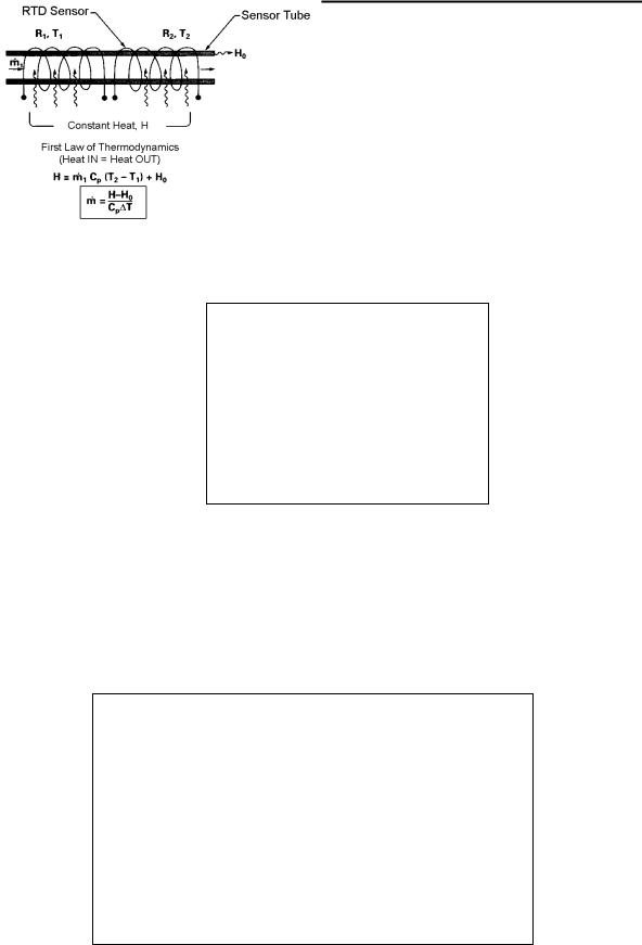
THE SMART-TRAK 2 FLOW SENSING PRINCIPLE
The operating principle of the Smart-Trak 2 instruments is based on heat transfer and the first law of thermodynamics. During operation process gas enters the instrument’s flow body and divides into two flow paths, one through the sensor tube, and the other through the laminar flow bypass. The laminar flow bypass (often called LFE which stands for “laminar flow element”) generates a pressure drop, P1– P2, forcing a small fraction of the total flow to pass through the sensor tube (m1).
Figure 1-1. Flow Paths through the Instrument
Two resistance temperature detector (RTD) coils around the sensor tube direct a constant amount of heat (H) into the gas stream. During operation, the gas mass flow carries heat from the upstream coil to the downstream coil. The resulting temperature difference (∆T) is measured by the Smart-Trak 2 microprocessor. From this, Smart-Trak 2 calculates the output signal. Since the molecules of the gas carry away the heat, the output signal is linearly proportional to gas mass flow.
Figure 1-2. Flow Measuring Principle
9

Sierra Instruments Instruction Manual |
Smart-Trak® 2 Series 100 |
||
|
|
|
|
|
|
|
|
|
|
|
|
Figure 1-3. Sensor Temperature Distribution
Figures 1-2 and 1-3 show the mass flow through the sensor tube as inversely proportional to the temperature difference of the coils. The coils are legs of a bridge circuit with an output voltage in direct proportion to the difference in the coils’ resistance; the result is the temperature difference (∆T). Two other parameters, heat input (H) and coefficient of specific heat (Cp) are both constant. Through careful design and attention to these parameters, this output signal is made linear over the transducer’s normal operating range (Figure 1-4). As a result, the measured flow through the sensor tube is directly proportional to the gas flow in the main body.
Figure 1-4. Linear Range of the Transducer’s Output Signal
In the Smart-Trak 2 mass flow controllers, the gas which flows through the monitoring section is precisely regulated by the built-in electromagnetic valve. The normally closed valve is similar to an on/off solenoid valve, except that the current to the valve coil, and hence the magnetic field, is modulated so that the ferromagnetic valve armature, or valve plug, assumes the exact height above the valve’s orifice required to maintain the valve’s command flow (set point). The result is excellent resolution.
10

Sierra Instruments Instruction Manual |
Smart-Trak® 2 Series 100 |
CHAPTER 2 INSTALLATION
Before You Begin Installation
Warning!
Injury can result if line pressure exceeds the maximum rating of 500 psig (34 barg).
Before installing the instrument, ensure that the installation site conforms to the specific operating parameters recorded on the instrument’s Data Label. The Data Label is mounted on the back of the instrument electronics enclosure (see sample Data Labels in Figure: 2-1). This is critical because each instrument is configured for a specific application range. Please review the gas or gases, the mounting orientation, the maximum flow range(s), the inlet and outlet pressure(s), and the operating temperature(s). The line pressure should not exceed 500 psig (34 barg). The temperature should not exceed 122°F (50°C). The minimum operating temperature is 32°F (0°C) and ambient temperature is 0-50°C. If your application exceeds any of these parameters, contact your Sierra Sales Agent before installation. You may also contact one of Sierra’s Technical Support Centers. FACTORY USA: TOLL FREE: 800-866-0200 or PHONE: 831-373-0200 or FAX: 831-373-4402 or EMAIL: service@sierrainstruments.com
Figure 2-1: Examples of Smart-Trak 2 Data Labels
11

Sierra Instruments Instruction Manual |
Smart-Trak® 2 Series 100 |
Pre-Installation Check List
1.Double-check to be sure that the O-ring material used in your instrument is compatible with the gas to be measured. The O-ring material used in your Smart-Trak 2 can be found in the Data Label. See Appendix A for a table of elastomer compatibility with a wide variety of gases.
2.Sierra strongly recommends you install an in-line filter upstream of the instrument. Recommended filter size: 10 micron. A 10 micron filter is available from Sierra as an accessory. See Appendix B or contact your local Sierra distributor.
3.Do not locate the instrument in areas subject to sudden temperature changes, excessive moisture or near equipment radiating significant amounts of heat. Be sure to allow adequate space for cable connectors and wiring.
4.For controllers, use a properly sized pressure regulator. Make sure the pressure regulator is not too small or too big. There can be no restrictions (such as valves, tubing or pipe internal diameters, reducers, etc.) upstream or downstream of the controller with a dimension that is less than the valve orifice diameter. To determine orifice diameter, consult the calibration certificate included with your instrument. If restricted, controller will not reach full scale.
5.Output Signals: The Smart-Trak 2 has two analog outputs that are linearly proportional to the gas mass flow rate, one voltage and one current. Choose from 0-20 mA or 4-20 mA for current plus one voltage signal: 0-5 VDC or 0-10 VDC or 1-5 VDC. The output signals specified at time of order will be indicated on the data label. You may change among the current and the voltage output signal at your discretion after receipt of the instrument using the Pilot Module or the Smart-Trak 2 Software (see Chapters 4 & 5). Changing the output signals has no influence on the instrument’s accuracy.
6.The CAT-5 connector on the side of the Smart-Trak 2 is NOT an Ethernet connector. It is for use with the optional Remote Pilot Module. Do not plug an Ethernet cable here as damage may result. Keep this connector covered if possible whenever it is not in use.
7.The instrument has specific power supply requirements. See the table later in this chapter for a complete listing of power requirements.
Installing the Instrument—Plumbing
Smart-Trak 2 instruments are supplied with compression, VCO®, VCR®, or female NPT process connections. To ensure a successful installation, inlet and outlet tubing
12

Sierra Instruments Instruction Manual |
Smart-Trak® 2 Series 100 |
should be clean prior to plumbing the instrument into the system. The shipping caps covering the inlet/outlet fittings should not be removed until immediately before installation.
Follow the installation instructions that are applicable to your instrument’s process connection. Ensure that the tubing is free from burrs or sharp rims that may result from cutting.
CAUTION: Before use, all plumbing should be checked carefully for leaks, especially at the connecting fittings. All instruments are leak-tested prior to shipping. It is not a requirement to leak test your instrument. Do not use liquid leak detectors such as Snoop® to search for leaks inside or outside the SmartTrak 2. Instead, monitor pressure decay.
Compression Fittings
1.Position the instrument with the flow direction arrow pointing in the direction of flow.
2.Verify the position of the front and back ferrule. Insert the tubing into
the fitting. Be sure that the tubing rests firmly on the shoulder of the fitting and that the nut is finger-tight. Scribe the nut at the six o’clock position.
3.While holding the fitting body steady with a backup wrench, tighten the nut 1-1/4 turns, watching the scribe mark make one complete revolution and continue to the nine o’clock position. For 1/16-inch, 1/8-inch and 3/16-inch (2, 3 and 4 mm) sizes, tighten only 3/4 turns from finger-tight. Do not overtighten!
4.If you use flexible tubing (Example: Polyflow) use an “Insert” (see www.swagelok.com)
5.Check the system’s entire flow path thoroughly for leaks. Do not use liquid leak detectors. Instead, monitor pressure decay. Exposing the instrument to leak detector fluid may cause damage.
VCO Fittings
1.Position the instrument with the flow direction arrow pointing in the direction of flow.
2.Tighten the nut finger-tight, and then 1/8 turn tighter with a wrench. Do not over-tighten!
13

Sierra Instruments Instruction Manual |
Smart-Trak® 2 Series 100 |
3.Check the system’s entire flow path thoroughly for leaks. Do not use liquid leak detectors. Instead, monitor pressure decay. Exposing the instrument to leak detector fluid may cause damage.
VCR Fittings
1.Position the instrument with the flow direction arrow pointing the direction of flow.
2.Install new gaskets that are compatible with the gas to be used.
3.Tighten the nut finger-tight, and then 1/8 turn tighter with a wrench. Do not over-tighten!
4.Check the system’s entire flow path thoroughly for leaks. Do not use liquid leak detectors. Instead, monitor pressure decay. Exposing the instrument to leak detector fluid may cause damage.
1/4 Inch Female NPT
1.Position the instrument with the flow direction arrow pointing the direction of flow.
2.Apply high quality Teflon tape to the male NPT fitting. Alternatively, use a high quality paste pipe thread sealant suitable for the application and gas, and apply this compound to the inlet and outlet fittings. Avoid getting the tape or the thread sealant onto the first two threads to keep it out of your process gas.
3.Tighten each fitting by hand. Then, tighten no more than one (1) turn. Do not over-tighten.
4.Check the system’s entire flow path thoroughly for leaks. Do not use liquid leak detectors. Instead, monitor pressure decay. Exposing the instrument to leak detector fluid may cause damage.
14

Sierra Instruments Instruction Manual |
Smart-Trak® 2 Series 100 |
Installing your Instrument—Mechanical Mounting
Mounting your Instrument
The base plate or bottom of the instrument has 4 mounting holes. Two are SAE thread and two are metric thread. For location and dimensions, please see Appendix E.
Your Smart-Trak 2 instrument is made from premium 316 stainless steel. As a result, it may require substantial mounting brackets to properly support its weight. Exercise caution when installing to avoid damage or injury.
Mounting the Optional Remote Pilot Module
If you have the optional Remote Pilot Module control unit, you have several mounting options.
1.Wall or Panel mounting—your Remote Pilot Module may be mounted to a flat surface using the supplied plate and 2 special “shoulder” screws. Simply screw the shoulder screws into the plate. Then, attach the plate to the wall by driving 2 screws (not included) through the 2 large central holes.
MAKE SURE THE UP ARROW IMPRINTED ON THE MOUNTING BRACKET POINTS UPWARD. Your Remote Pilot Module will slip onto the shoulder screws. Push against the plate and then down. To remove, push up and pull. Attach the CAT-5 cable to the socket on the bottom of the Remote Pilot Module.
2.Rack mounting—to mount your Remote Pilot Module to a standard 19” laboratory rack, first purchase a “blank” panel from your industrial supplier. Decide where the Remote Pilot Module will be attached, then follow the procedure listed above for wall mounting. When you are ready, insert the CAT-5 cable into the socket in the Remote Pilot Module.
3.Desktop mounting—the Remote Pilot Module will sit on a desk in a fashion that makes it convenient to view and operate. Insert the CAT-5 cable into the socket in the back of the Module. Use the cable as a “kickstand.” Gently bend the cable to recline the Remote Pilot Module to an angle suitable for easy viewing. Alternately, you can lay the Remote Pilot Module on its back and insert the CAT-5 cable into the socket in the bottom.
15

Sierra Instruments Instruction Manual |
Smart-Trak® 2 Series 100 |
Installing your Instrument—Electrical Connections
All electrical connections for your Smart-Trak 2 instrument are made on the left (inlet) side panel. See Figure 2-2: Smart-Trak 2 Connections below for the location of all connections. Note that the CAT-5 connector is not an ethernet connector.
CAT 5
HD DB 15
Figure 2-2: Smart-Trak 2 connections
16

Sierra Instruments Instruction Manual |
Smart-Trak® 2 Series 100 |
Smart-Trak 2 is provided with a high density 15-pin D Connector called an “HD DB-15” located on the side of the enclosure and either one of our optional preassembled communications cables or an empty mating connector. Power must be supplied to the HD DB-15 connector. Other features may be accessed there as well. The pin numbers and assignments for the HD DB-15 connector are shown in Figure 2-3: HD DB-15 Connector Pin Configuration (on the instrument). The corresponding colors of the optional communication cable wires and the functions of each are listed in Figure 2-4: Wiring Definitions for Optional Communication Cable. The connections for input power, analog output signal and analog input signal (controllers only) are all made at the HD DB-15 connector. There is a second copy of these 2 figures in Appendix D for your convenience
17

Sierra Instruments Instruction Manual |
Smart-Trak® 2 Series 100 |
Figure 2 3: HD DB 15 Connector Pin Configuration (on the instrument)
Figure 2 4: Wiring Definitions for Optional Communication Cable
Pin # |
Wire Color in Cable |
Function |
1. |
Brown |
Analog Ground/Output |
2. |
Red |
0-5 VDC Output (or 0-10, 1-5 VDC) |
3. |
Orange |
Analog Ground/RS232 |
4. |
Pink |
Valve Override Purge |
5. |
Yellow |
Power Return (-) |
6. |
Green |
Power Input (+) |
7. |
Green/White |
RS-232 Transmit (out) |
8. |
Blue |
Setpoint |
9. |
Purple |
Not Used |
10. |
Gray |
Analog Ground/Setpoint |
11. |
White |
Reference Voltage |
|
|
(5 VDC External Setpoint & Valve Purge) |
12. |
Black |
Valve Override Close |
13. |
Brown/white |
RS-232 Receive (in) |
14. |
Red/white |
4-20 mA Output |
15. |
Red/Black |
Not Used |
|
Shield Wire |
Chassis (Earth) Ground |
|
(no insulation) |
|
Note: Pins 1, 3, and 10 are connected together inside the instrument. Do not tie these grounds together outside the instrument. Must have one connection per analog ground. Recommended use listed.
18

Sierra Instruments Instruction Manual |
Smart-Trak® 2 Series 100 |
Instrument Power:
The Smart-Trak 2 requires a 15-24 VDC power supply. If you are using the power supply supplied by Sierra, connect it to the 15-pin HD DB-15 connector on the side of the instrument. If you are supplying your own power source, it must be a regulated 15-24 VDC with ripple not to exceed 100 mV peak-to-peak. It must be capable of producing the current specified for the appropriate voltage shown in Figure 2-5: Power Supply Requirements. Apply power as follows: positive (+) to the green (pin 6) and negative (-) to the yellow (pin 5) wires. The instrument is polarity sensitive. If you reverse this wiring, the instrument will not be damaged, but it will not function.
Instrument Grounding:
The Smart-Trak 2 has very high levels of RFI and EMI shielding built into the metal electronics cover (meets or exceeds the CE Standard EN 61326-1; 2006). To maintain the integrity of this CE rating, it is critical that a path be provided for any residual internal noise to exit the instrument or it may register on the outputs. Grounding provides this path.
To properly ground your instrument, secure the chassis to solid earth ground using the mounting holes on the bottom of the flow body. If the instrument will be used without permanent mounting (on a laboratory bench, for instance) then, using the provided cable, connect the shield wire (no insulation) to earth ground in your facility. If you purchased a Sierra power supply, a ground wire is provided for your convenience.
Figure 2-5: Power Supply Requirements |
|
|
|
|
Minimum Current |
Instrument Type |
Recommended Input |
|
|
Voltage |
Required (mA) |
M100L Meter |
15-24 VDC (+ 10%) |
230 |
M100M Meter |
15-24 VDC (+ 10%) |
230 |
M100H Meter |
15-24 VDC (+ 10%) |
230 |
C100L Controller |
24 + 10% VDC |
500 |
C100M Controller |
24 + 10% VDC |
800 |
C100H Controller |
24 + 10% VDC |
1260 |
NOTE: The Compod™ adds an additional 100mA to the ST2 current ratings.
CAUTION: This instrument is not a loop-powered device! Do NOT apply power to the 4-20 mA output or input connections.
19

Sierra Instruments Instruction Manual |
Smart-Trak® 2 Series 100 |
Analog Output Signals:
•Output Signal—Voltage: Measure the voltage output signal across the red (pin 2) wire and any of the analog grounds: brown (pin 1), orange (pin 3) or gray (pin 10). The minimum load is 1000 Ohms. We recommend pin 1. DO NOT USE THE SAME ANALOG GROUND FOR CURRENT OUTPUT, SETPOINT OR RS232.
•Output Signal—Current: Measure the current output signal, 4-20 mA or 0-20 mA, across the red/white stripe (pin 14) wire and any of the analog grounds: pin 1, 3, or 10. The maximum load is 500 Ohms. We recommend pin 1. DO NOT USE THE SAME ANALOG GROUND FOR VOLTAGE OUTPUT, SETPOINT OR RS232.
For Mass Flow Controllers, the following analog features are also available at the HD DB-15 connector:
Setpoint: To transmit an analog setpoint, supply the voltage or current signal (check the data label and/or setting) across the blue (pin 8) wire and pin 10.
Valve Close: To force the valve closed, connect the black (pin 12) wire to pin 10
Purge: To force the valve to its maximum open position which we call “Purge,” connect the pink (pin 4) wire to the white (pin 11) wire. Note that this will allow much greater flow than the rated full-scale value.
For Digital Communication Using Your Personal Computer:
You can communicate with your instrument using the Smart-Trak 2 Software package and your PC running the Windows operating system. Simply connect the light green (pin 7) wire, the brown/white stripe (pin 13) wire and one of the analog grounds (pin 1,3, or 10) to a standard DB-9 connector according to Figure 2-6: Digital Communication.
Figure 2-6: Digital Communication |
|
||
RS-232 |
Transmit (pin 7) |
to |
DB-9 pin #2 |
RS-232 |
Receive (pin 13) |
to |
DB-9 pin #3 |
Analog ground (pin 3) |
to |
DB-9 pin #5 |
|
20
Sierra Instruments Instruction Manual |
Smart-Trak® 2 Series 100 |
NOTE: Transit and Receive may need to be reversed, depending on which type of device or cable is connected. (No damage will result—attempt communication after reversal.
With the connections in Figure 2-6 in place, plug the DB-9 connector into an appropriate serial port on your PC.
To minimize the potential for RF interference, it is recommended to shield these wires. Use a metal DB-9 connector and connect one end of the shield to the DB-9 shell and the other end to the outer shell of the Smart-Trak 2 HD DB-15 connector.
CAUTION: The CAT-5 connector on the side of the Smart-Trak 2 is NOT an Ethernet connector. It is for use with the optional Remote Pilot Module or CRN
cable. Do not plug an Ethernet cable here as damage may result.
21

Sierra Instruments Instruction Manual |
Smart-Trak® 2 Series 100 |
CHAPTER 3: ANALOG OPERATION
Your Smart-Trak 2 instrument may be operated in three different ways:
THREE CONTROL OPTIONS
A.Analog Input/Output Operation (This Chapter): Using analog input/output signals at the 15-pin mini-D connector.
B.Digital Operation with Pilot Module (Chapter 4): Using the optional Pilot Module.
C.Digital Operation with RS-232 and Smart-Trak 2 Software (Chapter 5): Using the RS-232 link, the supplied Smart-Trak 2 Software package, and a PC-style computer running Windows operating system.
This chapter will discuss the first of these—Analog Operation. Please see subsequent chapters for other options.
Regardless of control options, the standard output for all Smart-Trak 2 instruments are two linear analog output signals corresponding to 0% to 100% of the mass flow fullscale range. Please note that one of these output signals is a current signal of either 4-20 or 0-20 mA. The other is a voltage signal of 0-5 VDC, 0-10 VDC or 1-5 VDC. You can choose any combination of these signals at any time in your facility.
For mass flow controllers, one input signal of 4-20 mA, 0-20 mA, 0-5 VDC, 0-10 VDC or 1-5 VDC (selectable by user) may be chosen to set the gas mass flow rate to any desired value within the range of the device. This input signal must be a direct linear representation of 0% to 100% of the desired gas mass flow full-scale value. For the location of these signals on the HD DB-15 connector, refer to Figure 2-4 or Appendix D.
Analog Operation, Mass Flow Meter
After your instrument is installed and the system has undergone a complete leak check as discussed in detail in Chapter 2, you are ready to supply power.
Power Your Instrument: Provide adequate power per Figure 2-5. Apply power using Sierra’s power supply or your own power source. The green LED at the top of the inlet side will light to confirm power. If your instrument has a Pilot Module, it will begin its start-up cycle. See Chapter 4 for details on Pilot Module operation. NOTE: It is highly recommended you connect power to the Smart-Trak 2, and then power your supply (plug into wall or switch on). The opposite may cause the unit to take longer to power on. Let the instrument warm up for at least 15 minutes for optimal performance.
Your Smart-Trak 2 instrument is now ready for use!
22

Sierra Instruments Instruction Manual |
Smart-Trak® 2 Series 100 |
Analog Operation, Mass Flow Controller
After your instrument is installed and the system has undergone a complete leak check as discussed in detail in Chapter 2, follow these steps:
1.The valve will remain closed until power is supplied. See Chapter 2 for wiring instructions. Remember that the valve in the Smart-Trak 2 is not a positive shut-off device. When power is applied, the flow control valve will operate per any instructions it receives. When the Smart-Trak 2 is delivered, the valve will be in the Automatic (Normal) state and the Pilot Module or analog signal will provide the correct zero setpoint reference for the instrument. As a result, the valve will be closed. However, upon subsequent power-ups, the valve will return to the state it was in the last time the instrument was operated.
CAUTION: If you do not know the value of the setpoint or the valve state given to the Smart-Trak 2 when it was last operated, you must assume that the valve will open when power is applied. Take necessary precautions.
You may use the Pilot Module or the Smart-Trak 2 Software to check the setpoint or the valve state currently on your instrument. See Chapter 4 or Chapter 5 for information on Setpoint and Valve State.
2.Power Your Instrument: Provide adequate power per Figure 2-5. Apply power using Sierra’s power supply or your own power source. The green LED at the top of the inlet side will light to confirm power. If your instrument has a Pilot Module, it will begin its start-up cycle. See Chapter 4 for details on Pilot Module operation. NOTE: It is highly recommended you connect power to the Smart-Trak 2, and then power your supply (plug into wall or switch on). The opposite may cause the unit to take longer to power on. Let the instrument warm up for at least 15 minutes for optimal performance.
3.Adjust the controller setpoint to the desired flow rate by supplying an appropriate signal (mA or VDC). The effective control range of the unit is 2% to 100% of the calibrated full scale flow range. Automatic shut-off occurs at 1.9% of the factory full scale calibrated range unless specifically modified at time of order. Smart-Trak 2 will immediately begin accurately monitoring and controlling the gas mass flow rate. Let the instrument warm up for at least 15 minutes for optimal performance.
Your Smart-Trak 2 instrument is now ready for use!
23

Sierra Instruments Instruction Manual |
Smart-Trak® 2 Series 100 |
Smart-Trak 2 Features
Setpoint Adjustment
The setpoint (command) input signal you supply to Smart-Trak 2 must be a direct linear representation of 0% to 100% of the mass flow full-scale value. Apply the setpoint signal from pin 8 to any of the analog grounds (see Chapter 2 for wiring details). A setpoint value of 0 VDC or mA (or 1 VDC or 4 mA) will regulate the flow to 0% and a setpoint value of 5.00 VDC (or 10 VDC or 20 mA) will adjust the flow to 100% of the instrument’s full scale range.
When the setpoint (command) signal is applied, the flow controller will reach the setpoint value within two seconds to within ±2% of the selected flow rate.
CAUTION: DO NOT LEAVE A SETPOINT APPLIED FOR AN EXTENDED PERIOD OF TIME TO A CONTROLLER WHEN THE GAS SUPPLY IS SHUT OFF OR BLOCKED. Damage may result and the instrument will become hot to the touch. Instead, see below for use of the “Valve Close” feature which allows you to disable the valve while maintaining the setpoint signal. This may be set by the Pilot Module, the Smart-Trak 2 Software, or an external analog signal.
Changing the Output or Setpoint Signals
To modify the analog output or setpoint signals (from 4-20mA to 0-10Vdc, for example), you must use the Pilot Module or the Smart-Trak 2 Software. The data label will indicate the form these signals had when the instrument was last calibrated. We strongly recommend that you adapt the data label if the configuration is changed for future reference. See Chapter 4 or 5 for the necessary procedure.
Over-Range Condition
If the mass flow rate exceeds the full-scale range listed on the Smart-Trak 2 data label (see samples on page 2-1), the output signal will measure above full-scale. However, the device has not been calibrated for flows in excess of the calibrated full scale value and the value will be both non-linear and inaccurate if an over-range condition exists. Please be aware that the analog outputs can exceed full scale by as much as 20%, or more.
Once the over-range condition has been removed, it may take up to 30 seconds for the Smart-Trak 2 to recover and resume normal operation. An over-range condition will not harm the instrument.
24

Sierra Instruments Instruction Manual |
Smart-Trak® 2 Series 100 |
Manual Valve Override—Valve Close
Manual valve override is provided for all Sierra mass flow controllers. This feature includes both a valve close command and a valve maximum open command (called purge). When the valve is directed to close or to purge, it will no longer respond to a setpoint command.
FOR VALVE CLOSE: connect pin 12 to analog ground
Remember that the valve in the Smart-Trak 2 is not a positive shut-off device. The Controller will return to normal automatic operation about 4 seconds after pin 12 is left floating.
Manual Valve Override—Valve Purge Function
The purge function opens the controller valve completely for the purpose of quickly flushing unwanted gas from the flow path. When the valve is opened for purging, it allows flows far in excess of the rated full scale of the controller.
FOR VALVE PURGE: connect pin 4 to pin 11.
CAUTION: PURGE MODE ALLOWS FAR MORE GAS TO FLOW THROUGH THE CONTROLLER! BEFORE USING VALVE PURGE OPERATION, INSURE PROPER DOWNSTREAM CAPACITY AND VENTILATION.
Caution!
IMPORTANT NOTES ABOUT PURGING
Purging Non-Reactive Gases:
Purge your Smart-Trak 2 with clean, dry nitrogen for a minimum of two hours.
Purging Reactive Gases:
One of the following methods may be used:
Cycle purge. This is done by alternately evacuating and purging the instrument for 2 to 4 hours with clean, dry nitrogen.
Purge the instrument with clean, dry nitrogen for 18 to 24 hours.
Evacuate the instrument for 18 to 24 hours.
25

Sierra Instruments Instruction Manual |
Smart-Trak® 2 Series 100 |
IMPORTANT SAFETY NOTES ABOUT PURGING
WARNING: When toxic or corrosive gases are used, purge unit thoroughly with inert dry gas before disconnecting from the gas line to prevent personnel from being injured when coming in contact with the instrument.
WARNING: If an instrument used with a toxic or corrosive gas is returned to the factory, a Material Safety Data Sheet (MSDS) must be enclosed & attached to the outside of the box to alert Sierra personnel of the potential hazard. Also, make sure the inlet & outlet are securely sealed.
26

Sierra Instruments Instruction Manual |
Smart-Trak® 2 Series 100 |
CHAPTER 4: Digital Operation with Pilot Module
Your Smart-Trak 2 instrument may be operated in three different ways:
THREE CONTROL OPTIONS
A.Analog Input/Output Operation (Chapter 3): Using analog input/output signals at the HD DB-15 connector.
B.Digital Operation with Pilot Module (This Chapter): Using the optional Pilot Module.
C.Digital Operation with RS-232 and Smart-Trak 2 Software (Chapter 5): Using the RS-232 Smart-Trak 2 Software package and a computer running the Windows operating system.
This chapter will discuss the second of these—Digital Operation with the optional Pilot Module. Please see alternate chapters for other options.
Although you have chosen to use the optional Pilot Module, please note that all the Analog control functions are still available on your instrument. Consult Chapter 3 for details on Analog operation. Also, computer control using the RS-232 communication is available. See Chapter 5 for details on operation with a computer.
CAUTION—If RS-232 digital communication is to be used in conjunction with the Pilot Module, the HD DB15 connector must be properly wired with a three wire serial DB9 cable to your computer. Often, this is done with the same HD DB15 that supplies power to your instrument. You can run both RS-232 communication and Pilot Module communications in parallel, but the unit will only respond to one set of commands at a time. DO NOT attempt to control the unit simultaneously with both the Pilot Module and the computer, this can lock up the unit.
Introduction to Pilot Module Features and Capabilities
The optional Pilot Module functions as both display and a control unit for your Smart-Trak 2 instrument. The standard Pilot Module is available mounted directly on the face of your instrument or as a handheld / remote mountable control interface attached to the Smart-Trak 2 via a detachable cable.
27

Sierra Instruments Instruction Manual |
Smart-Trak® 2 Series 100 |
If your instrument has a standard Pilot Module mounted locally on the face of the unit, no additional set-up is required. See picture below.
On the other hand, if your instrument has a Remote Pilot Module, attach one end of the included Category 5 (CAT 5, also called RJ-45) connecting cable into the jack at the top of the instrument’s left side, immediately above the HD DB-15 connector. Next, place the other end into one of the two matching jacks on the Pilot Module. For your convenience, Sierra has provided two jacks—one on the back and one on the bottom of the Remote Pilot Module. You may use whichever jack is most convenient for your application as they both have identical functions.
The Pilot Module includes a large LCD graphic display screen and six buttons. The LCD will show a variety of information and the buttons can be used to view and modify this information. The convenient buttons are:
Left arrow Right arrow
Up arrow Down arrow Enter button
Escape button
28

Sierra Instruments Instruction Manual |
Smart-Trak® 2 Series 100 |
These are shown in the photo below:
Up, Down |
Escape |
Left, Right |
|
Enter
Pilot Module Operation, Mass Flow Meter
After your instrument is installed and the system has undergone a complete leak check as discussed in detail in Chapter 2, follow these steps:
1. Power Up Your Instrument: Apply power to your instrument. See Chapter 2,
Caution! |
Figure 2-5: Power Supply Requirements. When power is first applied, the Pilot |
|
Module will display: |
||
The Smart-Trak 2 is |
||
|
||
not a loop-powered |
|
|
device. Do not |
|
|
apply power to the |
Version |
|
4-20 mA outputs. |
||
2.04X |
||
|
||
|
Read Parameters |
Assuming no gas is flowing, after another 5-10 seconds the display will read:
Mass Flow
0.000 sl/m
29

Sierra Instruments Instruction Manual |
Smart-Trak® 2 Series 100 |
Air
NOTE: If gas is flowing the Pilot Module will immediately begin to accurately display the gas mass flow rate on the LCD panel. If you have chosen alternate units or another gas, the display will show the selected units instead of the above.
2.Open the gas supply: Smart-Trak 2 is now ready to monitor the gas mass flow rate. Let the instrument warm up for at least 15 minutes for optimal performance.
Your Smart-Trak 2 instrument is now ready for use!
Pilot Module Operation, Mass Flow Controllers
After your instrument is installed and the system has undergone a complete leak check as discussed in detail in Chapter 2, follow these steps:
1.The valve will remain closed until power is supplied. See Chapter 2 for wiring instructions.
CAUTION: Remember that the valve in the Smart-Trak 2 is not a guaranteed positive shut-off device. For dangerous applications, Sierra recommends use of an external shut-off safety valve.
When power is applied, the flow control valve will operate per the instructions it receives from the Pilot Module. When the Smart-Trak 2 is delivered, the valve will be in the Automatic (Normal) state and the Pilot Module will provide the correct zero setpoint reference. As a result, the valve will be closed. However, the valve will return to the state it was in the last time the instrument was operated.
WARNING: If you do not know the setpoint or the valve state of the Mass Flow Controller before it was shut down, you must assume that the valve will open when power is applied. TAKE NECESSARY PRECAUTIONS.
2.Power Up Your Instrument: Apply power to your instrument using Sierra’s power supply or your own input power source. See Chapter 2, Figure 2-5: Power Supply Requirements. When power is first applied, the Pilot Module will display:
Version
2.04X
Read Parameters
If no gas is flowing, after another 5-10 seconds the display will read:
30
 Loading...