


 AirLink LX40
Hardware User Guide
41112510 Rev 1
AirLink LX40 Series Hardware User Guide
Important
Notice
Safety and
Hazards
Due to the nature of wireless communications, transmission and reception of data can never be guaranteed. Data may be delayed, corrupted (i.e., have errors) or be totally lost. Although significant delays or losses of data are rare when wireless devices such as the Sierra Wireless modem are used in a normal manner with a well-constructed network, the Sierra Wireless modem should not be used in situations where failure to transmit or receive data could result in damage of any kind to the user or any other party, including but not limited to personal injury, death, or loss of property. Sierra Wireless accepts no responsibility for damages of any kind resulting from delays or errors in data transmitted or received using the Sierra Wireless modem, or for failure of the Sierra Wireless modem to transmit or receive such data.
Do not operate the Sierra Wireless modem in areas where blasting is in progress, near medical equipment, near life support equipment, or any equipment which may be susceptible to any form of radio interference. In such areas, the Sierra Wireless modem MUST BE POWERED OFF. The Sierra Wireless modem can transmit signals that could interfere with this equipment.
The driver or operator of any vehicle should not operate the Sierra Wireless modem while in control of a vehicle. Doing so will detract from the driver or operator's control and operation of that vehicle. In some states and provinces, operating such communications devices while in control of a vehicle is an offence.
Warning: EXPLOSION HAZARD–DO NOT DISCONNECT WHILE CIRCUIT IS LIVE UNLESS THE AREA IS KNOWN TO BE NON-HAZARDOUS.
Avertrissement: RISQUE D’EXPLOSION-NE PAS DEBRANCHER TANT QUE LE CIRCUIT EST SOURS TENSION, A MOINES QU’IL NE S’AGISSE D’UN EMPLACEMENT NON DANGEREUX.
Warning: DO NOT USE THE USB CONNECTOR IN A HAZARDOUS AREA.
Avertrissement: NE PAS UTILISER DE CONNECTEUR USB DANS LES ENVIRONNEMENTS DANGEREUX.
Warning: DO NOT USE THE RESET BUTTON IN A HAZARDOUS AREA.
Limitation of
Liability
Avertrissement: NE PAS UTILISER LE BOUTON DE RESET DANS UN ENVIRONNEMENT DANGEREUX.
The information in this manual is subject to change without notice and does not represent a commitment on the part of Sierra Wireless. SIERRA WIRELESS AND ITS AFFILIATES SPECIFICALLY DISCLAIM LIABILITY FOR ANY AND ALL DIRECT, INDIRECT, SPECIAL, GENERAL, INCIDENTAL, CONSEQUENTIAL, PUNITIVE OR EXEMPLARY DAMAGES INCLUDING, BUT NOT LIMITED TO, LOSS OF PROFITS OR REVENUE OR ANTICIPATED PROFITS OR REVENUE
Rev 1 November 2018 |
2 |
41112510 |

Preface
Patents
Copyright
Trademarks
Contact
Information
ARISING OUT OF THE USE OR INABILITY TO USE ANY SIERRA WIRELESS PRODUCT, EVEN IF SIERRA WIRELESS AND/OR ITS AFFILIATES HAS BEEN ADVISED OF THE POSSIBILITY OF SUCH DAMAGES OR THEY ARE FORESEEABLE OR FOR CLAIMS BY ANY THIRD PARTY.
Notwithstanding the foregoing, in no event shall Sierra Wireless and/or its affiliates aggregate liability arising under or in connection with the Sierra Wireless product, regardless of the number of events, occurrences, or claims giving rise to liability, be in excess of the price paid by the purchaser for the Sierra Wireless product.
This product may contain technology developed by or for Sierra Wireless Inc. This product includes technology licensed from QUALCOMM®. This product is manufactured or sold by Sierra Wireless Inc. or its affiliates under one or more patents licensed from MMP Portfolio Licensing.
© 2018 Sierra Wireless. All rights reserved.
Sierra Wireless®, AirPrime®, AirLink®, AirVantage® and the Sierra Wireless logo are registered trademarks of Sierra Wireless.
Windows® and Windows Vista® are registered trademarks of Microsoft Corporation.
Macintosh® and Mac OS X® are registered trademarks of Apple Inc., registered in the U.S. and other countries.
QUALCOMM® is a registered trademark of QUALCOMM Incorporated. Used under license.
Other trademarks are the property of their respective owners.
Sales information and technical |
Web: sierrawireless.com/company/contact-us/ |
support, including warranty and returns |
Global toll-free number: 1-877-687-7795 |
|
6:00 am to 5:00 pm PST |
|
|
Corporate and product information |
Web: sierrawireless.com |
|
|
Rev 1 November 2018 |
3 |
41112510 |


 Contents
Introduction to the LX40 . . . . . . . . . . . . . . . . . . . . . . . . . . . . . . . . . . . . . . . . . . . . . . . . . . .7
Key Features . . . . . . . . . . . . . . . . . . . . . . . . . . . . . . . . . . . . . . . . . . . . . . . . . . . . . . . . . 7 Description . . . . . . . . . . . . . . . . . . . . . . . . . . . . . . . . . . . . . . . . . . . . . . . . . . . . . . . . . . . 8 Sample Power Consumption Scenarios. . . . . . . . . . . . . . . . . . . . . . . . . . . . . . . . . . . . . 9 Accessories . . . . . . . . . . . . . . . . . . . . . . . . . . . . . . . . . . . . . . . . . . . . . . . . . . . . . . . . . . 9 Warranty. . . . . . . . . . . . . . . . . . . . . . . . . . . . . . . . . . . . . . . . . . . . . . . . . . . . . . . . . . . . . 9
Installation and Startup . . . . . . . . . . . . . . . . . . . . . . . . . . . . . . . . . . . . . . . . . . . . . . . . . .10
Tools and Materials Required. . . . . . . . . . . . . . . . . . . . . . . . . . . . . . . . . . . . . . . . . . . . 10
Installation Overview . . . . . . . . . . . . . . . . . . . . . . . . . . . . . . . . . . . . . . . . . . . . . . . . . . 10 Step 1—Insert the SIM Card . . . . . . . . . . . . . . . . . . . . . . . . . . . . . . . . . . . . . . . . . . . . 11 Step 2—Mount and Ground the LX40 Chassis . . . . . . . . . . . . . . . . . . . . . . . . . . . . . . 11 Grounding the LX40 . . . . . . . . . . . . . . . . . . . . . . . . . . . . . . . . . . . . . . . . . . . . . . . . .12 Flat Mount . . . . . . . . . . . . . . . . . . . . . . . . . . . . . . . . . . . . . . . . . . . . . . . . . . . . . . . .13 Mounting in a High Vibration Environment . . . . . . . . . . . . . . . . . . . . . . . . . . . . . . . .14 DIN Rail Mount . . . . . . . . . . . . . . . . . . . . . . . . . . . . . . . . . . . . . . . . . . . . . . . . . . . . .15 Step 3—Connect the Antennas . . . . . . . . . . . . . . . . . . . . . . . . . . . . . . . . . . . . . . . . . . 16 Recommended Antenna Separation . . . . . . . . . . . . . . . . . . . . . . . . . . . . . . . . . . . .17 Step 4—Connect the Data Cables. . . . . . . . . . . . . . . . . . . . . . . . . . . . . . . . . . . . . . . . 17 Step 5—Connect the Power . . . . . . . . . . . . . . . . . . . . . . . . . . . . . . . . . . . . . . . . . . . . 17 Cable Strain Relief . . . . . . . . . . . . . . . . . . . . . . . . . . . . . . . . . . . . . . . . . . . . . . . . . .18 Fusing . . . . . . . . . . . . . . . . . . . . . . . . . . . . . . . . . . . . . . . . . . . . . . . . . . . . . . . . . . .18 Power Connector on the LX40 . . . . . . . . . . . . . . . . . . . . . . . . . . . . . . . . . . . . . . . . .19
Wiring Diagrams . . . . . . . . . . . . . . . . . . . . . . . . . . . . . . . . . . . . . . . . . . . . . . . . . . . .20 Step 6—I/O Configuration. . . . . . . . . . . . . . . . . . . . . . . . . . . . . . . . . . . . . . . . . . . . . . 22 Step 7—Check the Router Operation . . . . . . . . . . . . . . . . . . . . . . . . . . . . . . . . . . . . . 28 LED Behavior . . . . . . . . . . . . . . . . . . . . . . . . . . . . . . . . . . . . . . . . . . . . . . . . . . . . . .29 Ethernet LEDs . . . . . . . . . . . . . . . . . . . . . . . . . . . . . . . . . . . . . . . . . . . . . . . . . . . . .30 Step 8—Configure the Software . . . . . . . . . . . . . . . . . . . . . . . . . . . . . . . . . . . . . . . . . 31 Reboot the LX40. . . . . . . . . . . . . . . . . . . . . . . . . . . . . . . . . . . . . . . . . . . . . . . . . . . . . . 32 Reset the LX40 to Factory Default Settings . . . . . . . . . . . . . . . . . . . . . . . . . . . . . . . . . 32 Recovery Mode . . . . . . . . . . . . . . . . . . . . . . . . . . . . . . . . . . . . . . . . . . . . . . . . . . . . . . 33
Rev 1 November 2018 |
4 |
41112510 |

Contents
Specifications . . . . . . . . . . . . . . . . . . . . . . . . . . . . . . . . . . . . . . . . . . . . . . . . . . . . . . . . . . 34
Certification and Interoperability . . . . . . . . . . . . . . . . . . . . . . . . . . . . . . . . . . . . . . . . . 34
Mobile Network Operator Certification. . . . . . . . . . . . . . . . . . . . . . . . . . . . . . . . . . . . . 34
Network Technology . . . . . . . . . . . . . . . . . . . . . . . . . . . . . . . . . . . . . . . . . . . . . . . . . . 35
Environmental Testing. . . . . . . . . . . . . . . . . . . . . . . . . . . . . . . . . . . . . . . . . . . . . . . . . 35
Host Interfaces. . . . . . . . . . . . . . . . . . . . . . . . . . . . . . . . . . . . . . . . . . . . . . . . . . . . . . . 36
SIM Card Interface. . . . . . . . . . . . . . . . . . . . . . . . . . . . . . . . . . . . . . . . . . . . . . . . . . . . 37
Mechanical Specifications . . . . . . . . . . . . . . . . . . . . . . . . . . . . . . . . . . . . . . . . . . . . . . 37
Screw Torque Settings. . . . . . . . . . . . . . . . . . . . . . . . . . . . . . . . . . . . . . . . . . . . . . . . . 37
Operating Voltage . . . . . . . . . . . . . . . . . . . . . . . . . . . . . . . . . . . . . . . . . . . . . . . . . . . . 37
Power Specifications . . . . . . . . . . . . . . . . . . . . . . . . . . . . . . . . . . . . . . . . . . . . . . . . 37
Protocols . . . . . . . . . . . . . . . . . . . . . . . . . . . . . . . . . . . . . . . . . . . . . . . . . . . . . . . . . . . 38
Wi-Fi Performance. . . . . . . . . . . . . . . . . . . . . . . . . . . . . . . . . . . . . . . . . . . . . . . . . . . . 39
Wi-Fi Channels Supported. . . . . . . . . . . . . . . . . . . . . . . . . . . . . . . . . . . . . . . . . . . . . . 39
Radio Frequency Bands . . . . . . . . . . . . . . . . . . . . . . . . . . . . . . . . . . . . . . . . . . . . . . . 40
Radio Module Conducted Transmit Power . . . . . . . . . . . . . . . . . . . . . . . . . . . . . . . . . 44
Mechanical Specifications . . . . . . . . . . . . . . . . . . . . . . . . . . . . . . . . . . . . . . . . . . . . . . 46
Regulatory Information . . . . . . . . . . . . . . . . . . . . . . . . . . . . . . . . . . . . . . . . . . . . . . . . . . 47
Important Information for North American Users. . . . . . . . . . . . . . . . . . . . . . . . . . . . . 47
RF Exposure . . . . . . . . . . . . . . . . . . . . . . . . . . . . . . . . . . . . . . . . . . . . . . . . . . . . . . 48
Accessories . . . . . . . . . . . . . . . . . . . . . . . . . . . . . . . . . . . . . . . . . . . . . . . . . . . . . . . . . . . 51
DC Power Cable (Black Connector) . . . . . . . . . . . . . . . . . . . . . . . . . . . . . . . . . . . . . . 51
Rev 1 November 2018 |
5 |
41112510 |

AirLink LX40 Series Hardware User Guide
AC Power Adapter (Black Connector) . . . . . . . . . . . . . . . . . . . . . . . . . . . . . . . . . . . . . 52
AC Power Adapter Input . . . . . . . . . . . . . . . . . . . . . . . . . . . . . . . . . . . . . . . . . . . . . 52
AC Power Adapter Output . . . . . . . . . . . . . . . . . . . . . . . . . . . . . . . . . . . . . . . . . . . . 52
AC Power Adapter Environmental Specifications . . . . . . . . . . . . . . . . . . . . . . . . . . 53
AC Power Adapter Reliability and Quality Control . . . . . . . . . . . . . . . . . . . . . . . . . . 53
AC Power Adapter Safety Standards . . . . . . . . . . . . . . . . . . . . . . . . . . . . . . . . . . . 53
AC Power Adapter EMC Standards . . . . . . . . . . . . . . . . . . . . . . . . . . . . . . . . . . . . 53
AC Power Adapter Hazardous Substances . . . . . . . . . . . . . . . . . . . . . . . . . . . . . . . 54
AC Power Adapter Energy Efficiency . . . . . . . . . . . . . . . . . . . . . . . . . . . . . . . . . . . 54
Index. . . . . . . . . . . . . . . . . . . . . . . . . . . . . . . . . . . . . . . . . . . . . . . . . . . . . . . . . . . . . . . . . 55
Rev 1 November 2018 |
6 |
41112510 |

1: Introduction to the LX40 |
1 |
|
This hardware user guide is for the Sierra Wireless® AirLink® LX40 LTE Router.
Features and specifications described in this user guide apply to all variants of the
LX40 unless otherwise noted.
The AirLink LX40 is designed for Commercial and Enterprise LTE network connectivity.
LX40 provides purpose-built, secure, reliable, managed Cellular LTE networking in building automation, digital signage, taxis, ATMs, kiosks and point-of-sale terminals.
As part of the AirLink Essential series, the LX40 is designed to meet the environmental and performance requirements of these applications, while delivering superior reliability and uninterrupted operation in fixed, indoor and protected outdoor environments.
LX40 is available with optional Wi-Fi and rated for shock and vibration. It offers Dual
Band 802.11ac Wi-Fi.
The LX40 comes in LTE Cat 4 regional variants, and a Global LPWA (Low-Power Wide Area) variant offering LTE-M/NB-IoT for applications where low data rates, enhanced cellular coverage and global deployment is required.
Key Features
•LTE Cat-4 and Cat-M1/NB1 (LX40 variants)
•2.4/5 GHz 802.11ac Wi-Fi (Wi-Fi models only)
•Gigabit Ethernet port (LAN/WAN)
•1 configurable GPIO
•Power over Ethernet (IEEE 802.3af)
•USB 2.0 Micro-B Connector
For information on configuring these features, refer to the ALEOS Software
Configuration User Guide.
Rev 1 November 2018 |
7 |
41112510 |
AirLink LX40 Series Hardware User Guide
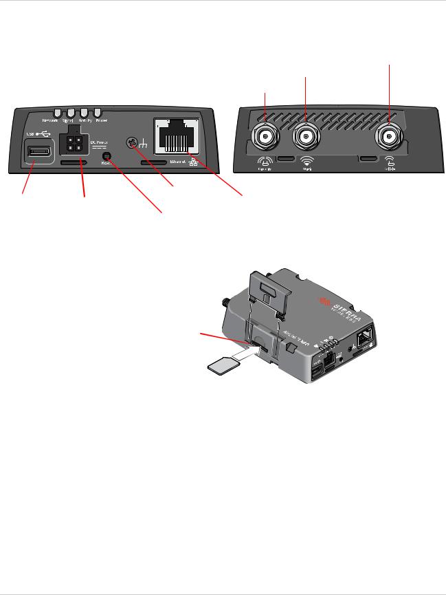
Description
(See Connect the Antennas on page 16.) Cellular Antenna Connector
Wi-Fi Antenna Connector*
LEDs (See LED Behavior on page 29.) Diversity Antenna Connector
|
|
|
|
|
|
|
|
|
|
|
|
|
|
|
|
|
*Wi-Fi model |
|
|
|
|
|
|
|
|
|
|
|
|
|
|
|
|
|
|
|
|
|
|
|
|
|
|
|
|
|
|
|
|
|
|
|
|
|
|
|
|
|
|
|
|
|
|
|
|
|
|
|
|
|
|
|
|
|
|
|
|
|
|
|
|
|
|
|
|
|
|
|
|
|
|
|
|
|
|
|
|
|
|
|
|
|
|
|
|
|
|
|
|
|
|
|
|
|
|
|
|
|
|
|
|
|
|
|
|
|
|
|
|
|
|
|
|
|
|
|
|
|
|
|
|
|
|
|
|
|
|
|
|
|
|
|
|
|
|
Grounding screw |
RJ-45 Ethernet Port |
||||
USB 2.0 Micro-AB Port |
|
Power |
|
|
(See page 11.) |
||||||||||||
(See USB on page 36.) |
|
(See |
|
|
|
|
|
|
|
(See Ethernet on page 36.) |
|||||||
|
Reset button |
|
|||||||||||||||
|
|
|
|
|
|
|
|
|
|
|
|||||||
|
|
|
|
|
|
|
|
|
|
(See page 32.) |
|
||||||
Mini-SIM 2FF Card slot (See Insert the SIM Card on page 18)
Figure 1-1: LX40 Connectors, LEDs and SIM Card Holder
Rev 1 November 2018 |
8 |
41112510 |

Introduction to the LX40
Sample Power Consumption Scenarios
Table 1-1: Power Consumption Scenarios
Scenario |
Radio |
Ethernet |
USB |
Wi-Fi |
Powera |
Standby Mode |
— |
— |
— |
— |
20 mW |
|
|
|
|
|
(1.7 mA) |
|
|
|
|
|
|
Ethernet |
Idle Attached |
10 BaseT Full duplex |
Disabled |
Disabled |
700 mW |
(10 BaseT) |
|
|
|
|
(58.3 mA) |
|
|
|
|
|
|
Ethernet |
Idle Attached |
100 BaseT Full duplex |
Disabled |
Disabled |
750 mW |
(100 BaseT) |
|
|
|
|
(62.5 mA) |
|
|
|
|
|
|
Ethernet (GigE) |
Idle Attached |
1000 BaseT Full duplex |
Disabled |
Disabled |
1000 mW |
|
|
|
|
|
(83.3 mA) |
|
|
|
|
|
|
Wi-Fi AP 5GHz |
Idle Attached |
Disabled |
Disabled |
Enabled |
1100 mW |
|
|
|
|
(idle) |
(91.6 mA) |
|
|
|
|
|
|
Typical Use |
Attached and |
100 BaseT Full duplex |
Enabled Idle |
Disabled |
3250 mW |
(non-Wi-Fi) |
connected (20 dBm) |
|
|
|
(270.8 mA) |
|
|
|
|
|
|
Typical Use |
Attached and |
100 BaseT Full duplex |
Enabled Idle |
Enabled |
3700 mW |
(Wi-Fi) |
connected (20 dBm) |
|
|
(idle) |
(308.3 mA) |
|
|
|
|
|
|
Maximum Power |
Attached and |
Enabled (1000 BaseT full |
Enabled |
Disabled |
5250 mW |
(non-Wi-Fi) |
connected (23 dBm) |
duplexwithAutonegotiation |
(pinging) |
|
(437.5 mA) |
|
|
as speed setting) |
|
|
|
|
|
|
|
|
|
Maximum Power |
Attached and |
Enabled (1000 BaseT full |
Enabled |
Enabled |
6250 mW |
(Wi-Fi) |
connected (23 dBm) |
duplex running with Auto |
(pinging) |
(1000 |
(520.8 mA) |
|
|
negotiation as speed |
|
BaseT full |
7500 mW |
|
|
setting) |
|
duplex |
(PoE) |
|
|
|
|
running) |
|
|
|
|
|
|
|
Inrush Current |
1 A @ 12 V (Averaged over 100 s) |
|
|
|
|
|
|
|
|
|
|
a. Power consumption was measured at 12 V unless noted.
Accessories
The following items come with the LX40 router:
•DC power cable
•Quick Start Guide
The following items can be ordered separately from Sierra Wireless:
•Universal AC power adapter (part number 2000579)
·Voltage input: 100–240 VAC
·Current output: 1.5 A
Warranty
The LX40 comes with a 3-year warranty, and has an optional 2-year warranty extension.
Rev 1 November 2018 |
9 |
41112510 |
2: Installation and Startup |
2 |
|
This chapter shows how to connect, install and start the AirLink LX40. It also describes the front panel LEDs, and I/O functionality.
Note: Field wiring and connections in hazardous locations must be connected as per the wiring methods requirement for Class 2 circuits mentioned in the National Electric Code and the Canadian Electric Code.
Note: The LX40 Series gateway installation must be done by a qualified technician.
Tools and Materials Required
•Power supply—AC or DC (DC power cable is supplied by Sierra Wireless)
·Not required if using Power over Ethernet
•A SIM card (provided by your mobile network operator)
•Small slot-head screwdriver (to remove SIM door)
•Computer with Ethernet cable
•LTE MIMO antennas—Main and Diversity
·Diversity antenna not required for CatM1/NB-IoT
•Wi-Fi antenna (LX40 Wi-Fi model only)
Installation Overview
The steps for a typical installation are:
1.Insert the SIM card—page 11.
2.Mount and ground the LX40 chassis—page 11.
3.Connect the antennas—page 16.
4.Connect the data cables—page 17.
5.Connect the power—page 17.
6.Check the router operation—page 28.
7.Configure the software—page 31.
The following sections describe these steps in detail. Read these sections carefully before performing the installation.
Warning: The default ACEmanager password is printed on the device label. You should always change the default password after logging in to ACEmanager. However, if the unit must be reset to factory default settings, your custom password may also be reset to default (depending on the Reset Mode configured in ACEmanager). Before installation, please record the default password and store it in a secure place. See also Reset the LX40 to Factory Default Settings on page 32.
Rev 1 November 2018 |
10 |
41112510 |
Installation and Startup
Note: Depending on where you are installing the LX40, you may want to mount the router before connecting the antenna, cables and power.
Step 1—Insert the SIM Card
If the SIM card has not already been installed, insert the SIM card into the router before connecting any external equipment or power to the router.
To install the SIM card:
1.Remove the SIM card cover. Press the tab with a screwdriver while sliding the cover upwards.
2.Orient the SIM card as shown in Figure 2-1 (with the gold contacts facing down).
3.Gently slide the SIM card into the slot until it clicks into place.
To remove the SIM card, press the SIM card in, and release it. Gently grip the SIM card and pull it out.
4.Replace the SIM card cover.
Note the orientation of notched corner for proper SIM card alignment.
Figure 2-1: Installing the SIM Card
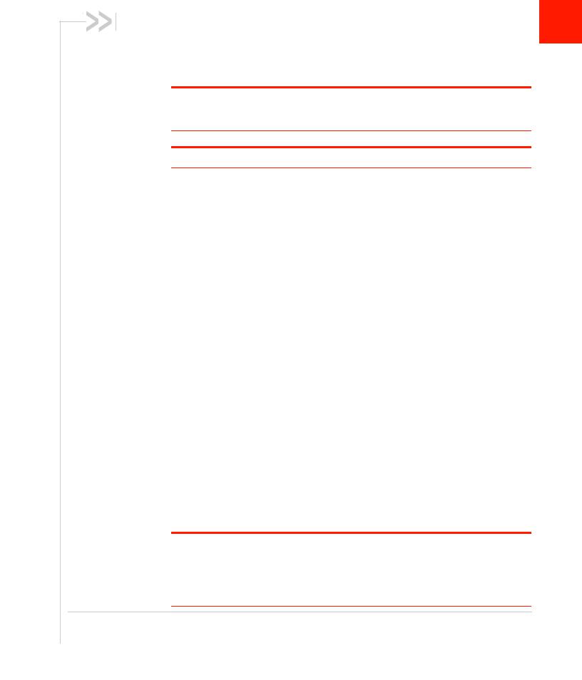
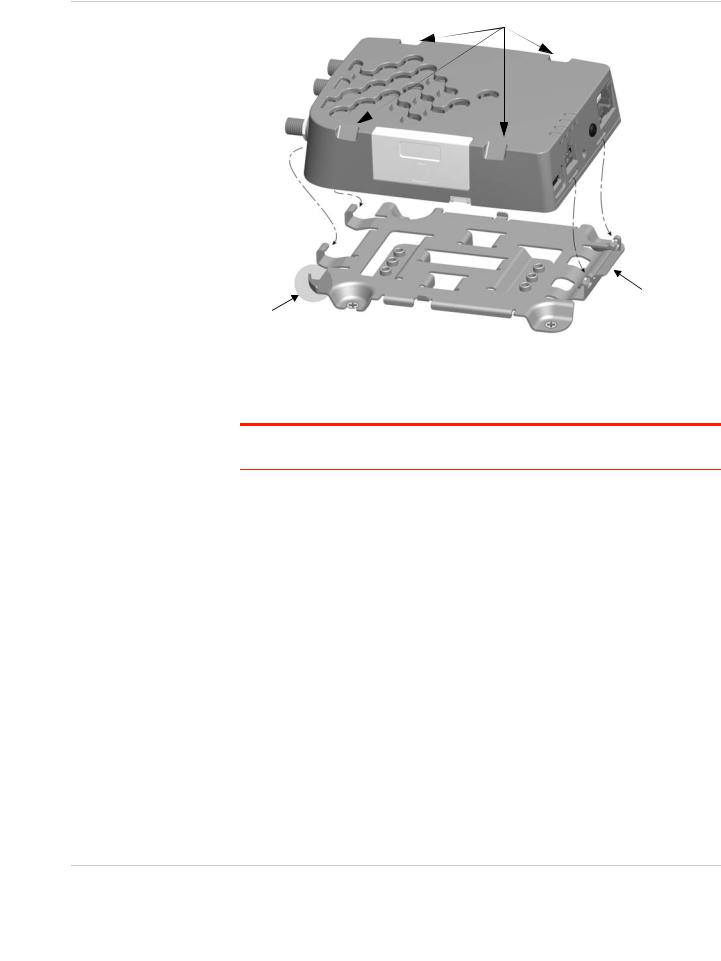
Step 2—Mount and Ground the LX40 Chassis
You can mount the LX40 on a flat surface, and secure it using a mounting bracket (see Flat Mount on page 13). If you are installing the LX40 in a high-vibration environment, you can further secure the LX40 to the mounting bracket using nylon cable ties.
Mount the router where:
•There is easy access for attaching the cables
•Cables will not be constricted, close to high amperages or exposed to extreme temperatures
Rev 1 November 2018 |
11 |
41112510 |

AirLink LX40 Series Hardware User Guide
•The front panel LEDs are easily visible
•There is adequate airflow
•It is away from direct exposure to the elements, such as sun, rain, dust, etc.
79 mm
3 1/8 in.
103 mm
4 1/16 in.
Figure 2-2: Mounting and Grounding the LX40
Grounding the LX40
Sierra Wireless strongly recommends that you always ground the chassis using the grounding point shown in Figure 2-3.
For DC installations (with a fixed “system” ground reference), Sierra Wireless recommends grounding the LX40 chassis to this system ground reference.
To ensure a good grounding reference, connect one end of a short 18 AWG or larger gauge wire with a ring terminal connector to the ground terminal on the LX40 and connect the other end to your main grounding point.
The ground terminal comes with an M2.5 × 6 mm screw. You can use a longer
M2.5 screw if the terminal connector on your ground wire requires one.
Note: Do not overtighten the grounding screw. Tighten to a maximum torque of 0.4 kg/cm.
Grounding point
Figure 2-3: Ground connector
Rev 1 November 2018 |
12 |
41112510 |
Installation and Startup
Flat Mount
To mount the LX40 permanently to any surface or if you are mounting the LX40 on a DIN rail, order an LX40 mounting bracket kit (P/N 6001221) from Sierra Wireless. The kit contains:
•Mounting bracket
•DIN rail clip (35 mm EN 50022) (see DIN Rail Mount on page 15)
•Screws for attaching the DIN rail clip to the mounting bracket
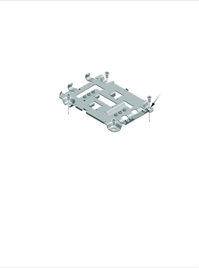
To mount the LX40 on a flat surface:
1.Attach the bracket to the mounting surface, using the attachment points shown in Figure 2-4.
Holes are Ø 4.3 mm (M4 compatible; use hardware appropriate for your mounting surface)
Figure 2-4: Mounting Bracket, showing attachment points
2.Snap the LX40 onto the bracket (see Figure 2-5 on page 14).
a.Angle the LX40 with the antenna connectors downwards, and fit the bracket clasps against the indentations on the end of the LX40. The raised edge of the bracket should match the rounded corner of the LX40.
b.Bring the other end of the LX40 down onto the bracket and snap it into place. The bracket clasps should fit into the indentations on the end of the LX40.
Rev 1 November 2018 |
13 |
41112510 |
AirLink LX40 Series Hardware User Guide
Notches for cable ties
Step a: Attach antenna end
Raised edge
Figure 2-5: Attaching the LX40 to the bracket
Step b: Snap other end into place.
Press the tab to disengage the clasps if removing the LX40.
Mounting in a High Vibration Environment
Note: If you are mounting the LX40 in a high vibration area, Sierra Wireless strongly recommends using two nylon cable ties to secure the LX40 on the bracket.
1.Thread the ties beneath the bracket.
2.Wrap the ties around the LX40, using the notches in the LX40 casing (see Figure 2-5) to align the ties.
3.Tighten and secure the ties around the LX40 and trim off the excess length of the ties.
Rev 1 November 2018 |
14 |
41112510 |
Installation and Startup
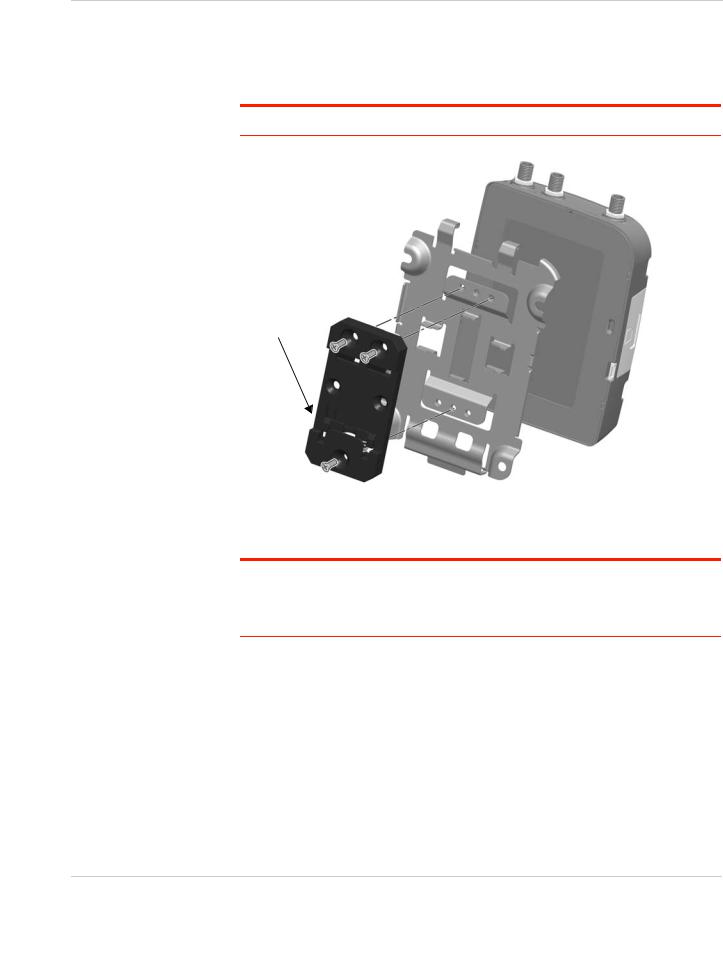
DIN Rail Mount
You can mount the LX40 on a DIN rail in a vertical orientation, with the antenna connectors pointing up or down.
Note: The DIN rail mounting clip should only be used on a horizontally-mounted DIN rail.
Ensure spring clip is at the bottom
To mount the LX40 with antenna connectors pointing down, rotate the DIN clip 180 degrees before attaching.
Figure 2-6: Attaching the DIN Rail Mounting Clip
To attach the LX40 to a horizontally mounted DIN rail:
Note: Before installing the LX40 in its final location, you may want to install the SIM card (see page 11), attach antennas (see page 16), power up the device (see page 17) and test the network connectivity (see page 28). After a successful test, you can remove cables and antennas and proceed with the procedure below.
1.Secure the LX40 in the mounting bracket, as described on page 13.
2.Use the screws provided to attach the DIN clip to the bracket. Attach the clip in the direction to achieve the desired position for the LX40. In the final orientation, the spring clip should be at the bottom. Torque the screws to a maximum of 1.1 N-m (10 in-lb.).
3.Attach the DIN rail clip to a horizontal DIN rail, with the spring clip at the bottom.
Rev 1 November 2018 |
15 |
41112510 |

AirLink LX40 Series Hardware User Guide
Note: Take extra care when attaching the antennas to the SMA connectors. Finger tight (approximately 0.6– 0.8 Nm 5–7 in-lb.) is sufficient and the max torque should not go beyond
1.1 Nm (10 in-lb.).
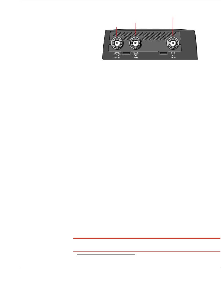
Step 3—Connect the Antennas
Warning: This router is not intended for use close to the human body. Antennas should be at least 8 inches (20 cm) away from the operator.
The LX40 has two SMA female antenna connectors:
•Cellular antenna connector: Primary receive and transmit antenna connector
•Cellular Diversity antenna connector: LTE MIMO and 3G Diversity
The AirLink LX40 with Wi-Fi also has:
•One reverse polarity SMA male connector for the Wi-Fi antenna. Sierra Wireless recommends cabling out the antenna.
The LX40 supports 2.4 GHz (2400–2500 MHz) and 5GHz
(4900–5900 MHz) Wi-Fi bands. See Wi-Fi Channels Supported on page 39 for more information.
For regulatory requirements concerning antennas, see Maximum Antenna Gain on page 48.
Note: The antenna should not exceed the maximum gain specified in RF Exposure on page 48. In more complex installations (such as those requiring long lengths of cable and/ or multiple connections), you must follow the maximum dBi gain guidelines specified by the radio communications regulations of the Federal Communications Commission (FCC), Industry Canada, or your country’s regulatory body.
To install the antennas:
1.Connect the cellular antenna to the SMA cellular antenna connector.
Mount the cellular antenna so there is at least 20 cm between the antenna and the user or bystander.
2.Connect a second antenna to the SMA diversity antenna connector.
For 3G networks, the second antenna operates as a diversity antenna, providing a second receive path.
For 4G networks, the second antenna operates as a MIMO antenna, providing a second receive path and a second transmit path.
3.For Wi-Fi-capable routers, connect the Wi-Fi antenna to the SMA Wi-Fi connector.
Note: If the antennas are located away from the router, keep the cables as short as possible to prevent the loss of antenna gain. Route the cables so that they are protected from damage and will not be snagged or pulled on. There should be no binding or sharp corners in the cable routing. Excess cabling should be bundled and tied off. Make sure the cables are secured so their weight will not loosen the connectors from the router over time.
Rev 1 November 2018 |
16 |
41112510 |
Installation and Startup
Cellular antenna connector
Wi-Fi antenna connector
Diversity antenna connector
Figure 2-7: Antenna Connectors
Recommended Antenna Separation
The recommended antenna separation is related to the band frequency/ wavelength. To accommodate the shortest frequency/longest wavelength band supported by the LX40, Sierra Wireless recommends a minimum antenna separation of 214 mm for best results, and if necessary, a separation of 107 mm for acceptable results.
Table 2-1: Frequency / Wavelength Range and Recommended Antenna Separation for the AirLink LX40
Service |
Wavelength Range for LX40 |
Frequency |
Wavelength |
Best Antenna |
Good Antenna |
|
|
(MHz) |
( ) (mm) |
Separation (mm) (1/2 ) |
Separation (mm) (1/4 ) |
|
|
|
|
|
|
LTE |
Longest |
700 |
428 |
214 |
107 |
|
|
|
|
|
|
LTE |
Shortest |
2600 |
115 |
58 |
29 |
|
|
|
|
|
|
Step 4—Connect the Data Cables
The LX40 has the following ports for connecting data cables:
•USB (Micro-AB)
•Ethernet (RJ-45)—Use a Cat 5e or Cat 6 Ethernet cable
Step 5—Connect the Power
The AirLink LX40 comes with a 3 meter (10 ft.) DC power cable. You can also purchase an optional AC adapter.
The LX40 can also use Power over Ethernet. An Ethernet cable connected to a compatible1 network switch or router can supply power to the LX40. No connection to the LX40 power connector (see Figure 2-8 on page 19) is required.
Warning: Electrical installations are potentially dangerous and should be performed by personnel thoroughly trained in safe electrical wiring procedures.
1. The LX40 is a 802.3af Powered Device
Rev 1 November 2018 |
17 |
41112510 |
 Loading...