


Series 830/840/860 Instruction Manual |
Table of Contents |
|
|
Sierra Series 830/840/860
Side-Trak™ and Auto-Trak™
Mass Flow Meters and Controllers
Instruction Manual
Part Number IM-83/84/86
Revision G .1 - 2-06
5 Harris Court, Building L Monterey, CA 93940
(831) 373-0200 (800) 866-0200 Fax (831) 373-4402
http://www.sierrainstruments.com
Sierra Instruments b.v. Bolstoen 30A 1046 AV Amsterdam The Netherlands +31(0)20-6145810 Fax +31(0)20-6145815
|
IM-83/84/86-H |
0-1 |
|
|
|
|
|
Table of Contents |
Series 830/840/860 Instruction Manual |
|
|
Customer Notice
Sierra Instruments, Inc. is not liable for any damage or personal injury, whatsoever, resulting from the use of Sierra Instruments standard mass flow meters or controllers for oxygen gas. You are responsible for determining if this mass flow meter or controller is appropriate for your oxygen application. You are responsible for cleaning the mass flow meter or controller to the degree required for your oxygen flow application.
© COPYRIGHT SIERRA INSTRUMENTS 1994
No part of this publication may be copied or distributed, transmitted, transcribed, stored in a retrieval system, or translated into any human or computer language, in any form or by any means, electronic, mechanical, manual, or otherwise, or disclosed to third parties without the express written permission of Sierra Instruments. The information contained in this manual is subject to change without notice.
TRADEMARKS
Side-Trak™, Auto-Trak™ and Cal-Bench™ are trademarks of Sierra Instruments, Inc. Other product and company names listed in this manual are trademarks or trade names of their respective manufacturers.
0-2 |
IM-83/84/86-H |

Series 830/840/860 Instruction Manual |
Table of Contents |
|
|
Revision F changes: Add wiring designations for 15-pin and 20-pin connectors. Correct units on page A-1, Example 1.
IM-83/84/86-H |
0-3 |

Table of Contents Series 830/840/860 Instruction Manual
Table of Contents
Chapter 1 Introduction
Introduction.............................................................................. |
1-1 |
Using this Manual............................................................... |
1-1 |
Safety Information.............................................................. |
1-2 |
Receipt of System Components .......................................... |
1-2 |
Technical Assistance .......................................................... |
1-2 |
The Series 800 Flow Sensing Principle..................................... |
1-3 |
Chapter 2 Installation
Quick Installation Guide........................................................... |
2-1 |
Installation Overview ............................................................... |
2-2 |
Installing the Transducer .......................................................... |
2-3 |
Compression Fittings.......................................................... |
2-3 |
VCO Fittings...................................................................... |
2-3 |
VCR Fittings ...................................................................... |
2-4 |
NPT and 1/2-inch Fittings................................................... |
2-4 |
Wiring the Transducer.............................................................. |
2-5 |
Recommended Wire Gauges............................................... |
2-5 |
Wiring Transducers with 20-Pin Card Edge Connectors ..... |
2-6 |
Wiring Transducers with 15-Pin D Connectors................. |
2-10 |
Motor-Operated Valve Circular 10-Pin Connector............ |
2-14 |
Chapter 3 Operation
Mass Flow Meter Operation ..................................................... |
3-1 |
Mass Flow Controller Operation............................................... |
3-2 |
Electromagnetic Valve Controllers ..................................... |
3-2 |
Motor-Operated Rotary Valve Controllers.......................... |
3-3 |
Mass Flow Controller Features................................................. |
3-4 |
Over-Range and Cold Sensor Lockout Circuit .................... |
3-4 |
Controller Auto Shut-Off Feature ....................................... |
3-4 |
On-Off Control and Soft Start Option................................. |
3-5 |
Valve Purge Function......................................................... |
3-6 |
Chapter 4 Maintenance
Flow Path Maintenance ............................................................ |
4-1 |
Changing the Laminar Flow Element.................................. |
4-1 |
Sensor Maintenance ................................................................. |
4-6 |
Sensor Cleaning and Inspection.......................................... |
4-6 |
Sensor Electrical Test ......................................................... |
4-7 |
Valve Maintenance................................................................... |
4-8 |
|
|
0-4 |
IM-83/84/86-H |

Series 830/840/860 Instruction Manual |
Table of Contents |
|
|
Electromagnetic Valves - Low and Medium Flow |
.............. 4-8 |
Electromagnetic Valves - High Flow |
4-9 |
Motor-Operated Rotary Valves ........................................ |
4-11 |
Valve Adjustment ............................................................ |
4-12 |
Transducer Calibration..................................................... |
4-15 |
Chapter 5 Troubleshooting |
|
Troubleshooting Procedures..................................................... |
5-1 |
Frequently Asked Questions .................................................... |
5-4 |
Returning Equipment to the Factory......................................... |
5-7 |
Appendix A Conversion Formulas and Gas Tables
Appendix B Production Specifications
List of Figures
1-1. |
Flow Paths through the Transducer................................ |
1-3 |
1-2. |
Flow Measuring Principle.............................................. |
1-3 |
1-3. |
Sensor Temperature Distribution ................................... |
1-4 |
1-4. |
Linear Range of the Transducer’s Output Signal............ |
1-4 |
2-1. |
Piping Requirements for NPT & 1/2-inch Connections .. |
2-3 |
2-2. |
Input Power Connections (20-Pin Connector) ................ |
2-5 |
2-3. |
Output Signal Connections (20-Pin Connector).............. |
2-5 |
2-4. |
Local Command Set Point (20-Pin Connector)............... |
2-6 |
2-5. |
External Command Set Point (20-Pin Connector) .......... |
2-6 |
2-6. |
15 Volt Valve Purge and Off (20-Pin Connector)........... |
2-7 |
2-7. |
30 Volt Valve Purge and Off (20-Pin Connector)........... |
2-7 |
2-8. |
Input Power (15-Pin D Connector)................................. |
2-8 |
2-9. |
Output Signal (15-Pin D Connector).............................. |
2-8 |
2-10. |
Local Command Set Point (15-Pin D Connector)........... |
2-9 |
2-11. |
External Command Set Point (15-Pin D Connector)....... |
2-9 |
2-12. |
15 Volt Valve Purge and Off (15-Pin D Connector)..... |
2-10 |
2-13. |
30 Volt Valve Purge and Off (15-Pin D Connector)..... |
2-10 |
2-14. |
Motor-Operated Valve Circular 10-Pin Connector ....... |
2-11 |
3-1. |
Soft Start Response Times ............................................. |
3-5 |
4-1. |
Low Flow Transducer LFE Cleaning ............................. |
4-2 |
4-2. |
Medium Flow Transducer LFE Cleaning ....................... |
4-3 |
4-3. |
High Flow Transducer LFE Cleaning............................. |
4-4 |
4-4. |
NPT Transducer LFE Cleaning...................................... |
4-5 |
4-5. |
Sensor Wire Access ....................................................... |
4-7 |
4-6. |
Transducer Potentiometers Used for Calibration.......... |
4-12 |
IM-83/84/86-H |
0-5 |

Table of Contents Series 830/840/860 Instruction Manual
List of Tables
2-1. Recommended Wire Gauges .......................................... |
2-4 |
0-6 |
IM-83/84/86-H |
Series 830/840/860 Instruction Manual |
Table of Contents |
|
|
Warnings and Cautions
Warning! Follow National Electric Code or your local code safety practices when wiring or connecting this unit to a power source. Only qualified personnel should install and wire the transducer.
Warning! Always remove main power before disassembling the transducer.
Caution! During operation, the mass flow controller valve becomes hot.
Caution! Do not use the manual purge function when RS-485 is active (Model 860 only).
Caution! Always fully neutralize any toxic gas trapped inside the transducer before removing from the gas line.
Caution! Only qualified personnel should perform transducer service, calibration or troubleshooting procedures.
Caution! Printed circuit boards are sensitive to electrostatic discharge. To avoid damaging the board, follow these precautions to minimize the risk of damage:
•before handling the assembly, discharge your body by touching a grounded, metal object
•handle all cards by their edges unless otherwise required
•when possible, use grounded electrostatic discharge wrist straps when handling sensitive components
IM-83/84/86-H |
0-7 |

Series 830/840/860 Instruction Manual |
Chapter 1 Introduction |
|
|
Chapter 1 Introduction
Sierra’s Side-Trak™ and Auto-Trak™ mass flow meters and controllers are designed to accurately measure and control flows of process gases. This instruction manual covers the installation, operation and maintenance of the entire Side-Trak and Auto-Trak product lines, which include the following Sierra models:
•830 Side-Trak Mass Flow Meter
•840 Side-Trak Mass Flow Controller
•860M Auto-Trak Mass Flow Meter with RS-485 interface
•860C Auto-Trak Mass Flow Controller with RS-485 interface
Sierra’s mass flow meters and controllers offer a broad range of sizes, control electronics, process connections, cables and connectors for flexibility and versatility. The meter’s patented straight sensor tube with access ports permits easy cleaning and reduces maintenance down-time. The platinum sensor eliminates zero-drift and ensures long-term repeatability. The primary standard calibration ensures starting point accuracy and NIST traceability. All wetted surfaces are constructed of 316 stainless steel with Viton® seals standard. Controllers incorporate either an electromagnetic valve (up to 500 slpm) or a motor-operated rotary valve (100 slpm to 200 scfm). The Auto-Trak 860 digital microprocessor features automatic bridge-balancing circuitry and provides simultaneous analog and digital RS-485 communication.
Using This Manual
This manual is organized into five chapters:
•Chapter 1 includes the introduction and theory of operation
•Chapter 2 provides installation and wiring instructions
•Chapter 3 describes system operation and controller features
•Chapter 4 covers maintenance and calibration procedures
•Chapter 5 provides troubleshooting advice
Gas tables and conversion formulas are found in Appendix A. The product specifications and dimensional drawings are found in Appendix B.
The Model 860 Auto-Trak RS-485 communications program includes an “Auto-Net” Software Addendum as a supplement to this manual. Please refer to this addendum for all RS-485 operating instructions.
IM-83/84/86-H |
1-1 |

Chapter 1 Introduction |
Series 830/840/860 Instruction Manual |
|
|
Throughout this manual, we use the word transducer as a generic term to represent all Side-Trak and Auto-Trak mass flow meters and controllers.
1-2 |
IM-83/84/86-H |

Series 830/840/860 Instruction Manual |
Chapter 1 Introduction |
|
|
Safety Information
Caution and warning statements are used throughout this book to draw your attention to important information.
Warning! |
Caution! |
This statement appears with information that is important to protect people and equipment from damage. Pay very close attention to all warnings that apply to your application.
This statement appears with information that is important for protecting your equipment and performance. Read and follow all cautions that apply to your application.
Receipt of System Components
When receiving a Sierra transducer, carefully check the outside packing carton for damage incurred in shipment. If the carton is damaged, notify the local carrier and submit a report to the factory or distributor. Remove the packing slip and check that all ordered components are present and match your specifications (as ordered). Make sure any spare parts or accessories are not discarded with the packing material. Do not return any equipment to the factory without first contacting Sierra Customer Service.
Technical Assistance
If you encounter a problem with your transducer, review the configuration information for each step of the installation, operation and set up procedures. Verify that your settings and adjustments are consistent with factory recommendations. Refer to Chapter 5, Troubleshooting, for specific information and recommendations.
If the problem persists after following the troubleshooting procedures outlined in Chapter 5, contact Sierra Instruments by fax or by E-mail (see inside front cover). For urgent phone support you may call (800) 866-0200 or (831) 373-0200 between 8:00 a.m. and 5:00 p.m. PST. In Europe contact Sierra Instruments bv at +31 20 6145810. When contacting Technical Support, make sure to include this information:
•the flow range, serial number and Sierra order number and model number (all marked on the transducer nameplate)
•the problem you are encountering and any corrective action taken
•application information (gas, pressure, temperature and piping configuration)
IM-83/84/86-H |
1-3 |
Chapter 1 Introduction |
Series 830/840/860 Instruction Manual |
|
|
The Series 800 Flow Sensing Principle
The operating principle of Sierra’s Side-Trak and Auto-Trak flow meters and controllers is based on heat transfer and the first law of thermodynamics. During operation process gas enters the instrument’s flow body and divides into two flow paths, one through the sensor tube, the other through the laminar flow element bypass. The laminar flow element bypass generates a pressure drop, P1–P2, forcing a small fraction of the total flow to pass through the sensor tube (m1) which is then monitored.
Figure 1-1. Flow Paths through the Transducer
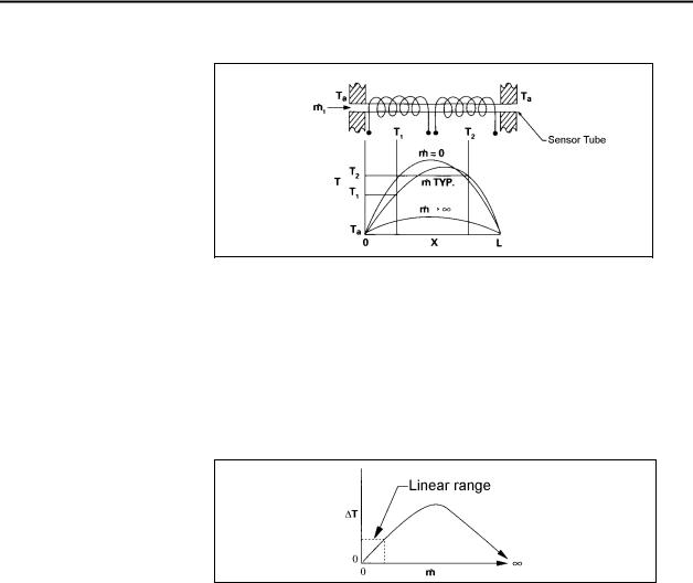
Two resistance temperature detector (RTD) coils around the sensor tube direct a constant amount of heat (H) into the gas stream. In actual operation, the gas mass flow carries heat from the upstream coil to the downstream coil. The resulting temperature difference (∆T) is detected by the RTD coils.
Figure 1-2. Flow Measuring Principle
1-4 |
IM-83/84/86-H |
Series 830/840/860 Instruction Manual |
Chapter 1 Introduction |
|
|
Figure 1-3. Sensor Temperature Distribution
Figures 1-2 and 1-3 show the mass flow through the sensor tube as inversely proportional to the temperature difference of the coils. The coils are legs of a bridge circuit with an output voltage in direct proportion to the difference in the coils’ resistance; the result is the temperature difference (∆T). Two other parameters, heat input (H) and coefficient of specific heat (Cp) are both constant. The resulting output is nearly linear over the transducer’s normal operating range.
Figure 1-4. Linear Range of the Transducer’s Output Signal
For mass flow controllers, once the gas flows through the monitoring section, it is then controlled by the built-in servo-control valve. For flows up to 500 slpm, Sierra’s proprietary high-efficiency FastTrak Electromagnetic Valve is used. The normally closed FastTrak valve is similar to an on/off solenoid valve, except that the current to the valve coil, and hence the magnetic field, is modulated so that the ferromagnetic valve armature, or valve plug, assumes the exact height above the valve’s orifice required to maintain the valve’s command flow. The result is nearly infinite resolution. All controllers with the Fast-Trak valves are available with a “Soft-Start” option for those processes that require it.
For higher flows of 50 to 200 scfm, controllers are equipped with Sierra’s microprocessor-controlled, motor-operated rotary valve. While the rotary valve does not provide a completely positive shut-off, it does offer accurate control for higher flow installations.
IM-83/84/86-H |
1-5 |

Series 830/840/860 Instruction Manual |
Chapter 2 Installation |
|
|
Chapter 2 Installation
Quick-Installation Instructions For
830/840 L, M and H Meters And Controllers
1.NEVER TEST FOR LEAKS WITH LIQUID LEAK DETECTOR. If liquid seeps into the electronics or the sensor compartment below, the instrument may be damaged. Use a pressure-decay test instead.
2.Install an appropriate in-line filter upstream if the gas contains any particulate matter or condensed moisture. (A 15-micron particulate filter for full-scale flows up to 30 liters/minute is recommended, 30 micron for flows above 30).
3.Mount with a horizontal gas-flow. This orientation is preferable unless the factory calibration was specifically performed for a vertical flow. Consult your calibration certificate. (Horizontal flow is assumed unless vertical flow upward or downward is specified).
4.DO NOT APPLY POWER TO THE OUTPUT LOOP on units equipped and calibrated for a 4-20 mA output signal. This is NOT a loop-powered device. Damage will occur.
5.Wire the instrument per the diagrams on the back of this card or the Operator’s Manual, Chapter 2. Controllers require a separate ground wire for the Valve Return signal as well as a Setpoint signal (no wire connected to the setpoint may cause the valve to float open).
6.Apply the gas listed on the label to the inlet at the recommended inlet pressure as listed on the calibration certificate. On a meter, obtain this pressure by blocking off the flow downstream. On a controller, confirm that there is no gas flowing through it with a zero setpoint. (If there is a flow, consult the Valve Adjustment Procedure in the manual).
7.Apply power and verify or adjust the zero setting after allowing a 15-minute warm-up period. The zero adjustment potentiometer is accessed through the upper hole in the side of the electronics cover. (See the Operator’s Manual, Chapter 3).
8.DO NOT LEAVE A SETPOINT APPLIED TO A CONTROLLER WHEN NO GAS IS AVAILABLE TO THE INLET FITTING. The control circuit will apply the maximum voltage to the valve coil resulting in eventual overheating. Damage may occur. (Instead, consult the Operator’s Manual for use of the “Valve Off” feature).
9.An ANNUAL factory evaluation and calibration is recommended.
Email Technical Support: Service@sierrainstruments.com
Website Self Service: www.sierrainstruments.com
IM-83/84/86-H |
2-1 |

Chapter 2 Installation |
Series 830/840/860 Instruction Manual |
|
|
Installation Overview
Side-Trak™ and Auto-Trak™ transducers are supplied with either compression, VCO, VCR or NPT process connections. To ensure a successful installation, inlet and outlet tubing should be in a clean state prior to plumbing the transducer into the system. The shipping caps covering the inlet/outlet fittings should not be removed until immediately prior to installation.
Before installing the transducer, verify the following:
1.Make sure the installation site meets the specific operating parameters recorded on the transducer’s nameplate. Each transducer is factory-configured for a specific gas and flow range, pressure differential, temperature range and mounting position.
2.Do not locate the transducer in areas subject to sudden temperature changes, moisture, drafts or near equipment radiating significant amounts of heat. Make sure to allow adequate space for cable connectors and wiring.
3.Make sure the location meets the minimum number of recommended pipe diameters upstream and downstream of any NPT or 1/2-inch process connection. A minimum of two inches is always recommended.
4.If the gas contains any particulate matter, install an in-line filter prior to the transducer. Recommended filter size: 15 micron for flows of 10 to 30 slpm, 30 micron for above 30 slpm.
5.If the transducer is mounted in any position other than horizontal and it was not calibrated specifically for that position, contact Sierra’s Customer Service Department for instructions.
6.For meters, if a potential over-flow condition exists, insert a valve or critical orifice in the line to limit flow to approximately 25 percent above the full scale range of the meter.
7.For controllers, use a properly-sized pressure controller and verify the controller orifice size is the smallest in the system. There can be no restrictions (such as valves, tubing or piping internal diameters, reducers, etc.) upstream or downstream of the controller less than the valve orifice diameter.
8.Confirm that the transducer o-ring material is compatible with the gas to be measured.
2-2 |
IM-83/84/86-H |
Series 830/840/860 Instruction Manual |
Chapter 2 Installation |
|
|
Caution!
Only qualified personnel should install the transducer.
Installing the Transducer
Follow the installation instructions that are applicable to your transducer’s process connection. For all NPT and 1/2-inch size fittings, see the piping recommendations given on page 2-3. Before use, all plumbing should be checked carefully for leaks and the transducer purged with dry nitrogen. Make sure that the tubing is free from burrs, or rims caused by cutting.
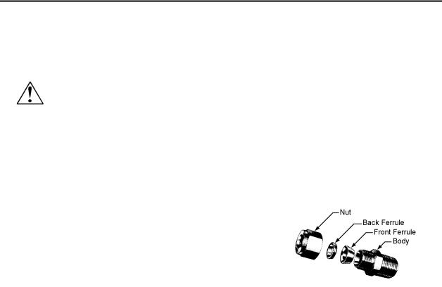
Compression Fittings
1.Position the transducer with the flow direction arrow pointing downstream in the direction
of flow.
2.Verify the position of the front and back ferrule as shown at right. Insert the tubing into the fitting. Make sure that the tubing rests
firmly on the shoulder of the fitting and that the nut is finger tight. Scribe the nut at the six o’clock position.
3.While holding the fitting body steady with a backup wrench, tighten the nut 1-1/4 turns, watching the scribe mark make one complete revolution and continue to the nine o’clock position. For 1/16-inch, 1/8-inch and 3/16-inch (2, 3 and 4 mm) sizes, tighten only 3/4 turn from finger tight. Do not over-tighten!
4.Check the system’s entire flow path thoroughly for leaks. (Do not use liquid leak detectors, instead monitor pressure decay. Over-exposing the transducer to leak detector fluid may damage the unit.)
VCO Fittings
1.Position the transducer with the flow direction arrow pointing downstream in the direction of flow.
2.Tighten the nut finger tight, and then 1/4 turn tighter with a wrench. Do not over-tighten!
3.Check the system’s entire flow path thoroughly for leaks. (Do not use liquid leak detectors, instead monitor pressure decay. Over-exposing the transducer to leak detector fluid may damage the unit.)
IM-83/84/86-H |
2-3 |
Chapter 2 Installation |
Series 830/840/860 Instruction Manual |
|
|
VCR Fittings
1.Position the transducer with the flow direction arrow pointing downstream in the direction of flow.
2.Install new washers compatible with the gas to be used. (Do not mix or interchange parts of tube fittings made by different manufacturers.)
3.Tighten the nut finger tight, and then 1/4 turn tighter with a wrench. Do not over-tighten!
4.Check the system’s entire flow path thoroughly for leaks. (Do not use liquid leak detectors, instead monitor pressure decay. Over-exposing the transducer to leak detector fluid may damage the unit.)
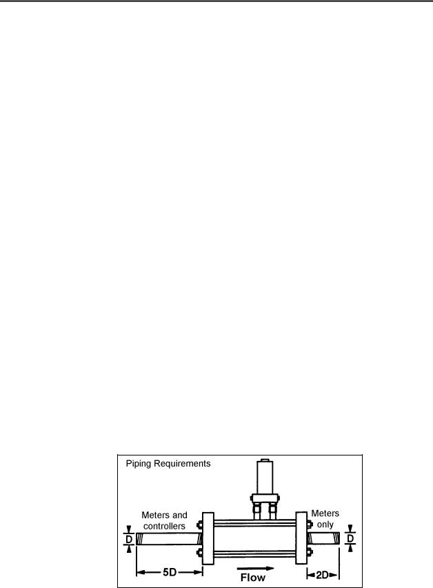
NPT Fittings and 1/2-Inch Connections - All Types
1.Install a section of straight pipe at least five pipe diameters in length upstream of the transducer. For flow meters only, also allow at least two pipe diameters downstream for accurate operation. DO NOT use reducers.
2.Position the transducer with the flow direction arrow pointing downstream in the direction of flow.
3.Tighten fittings until leak tight (refer to published standards for specific recommendations).
4.Check the system’s entire flow path thoroughly for leaks. (Do not use liquid leak detectors, instead monitor pressure decay. Over-exposing the transducer to leak detector fluid may damage the unit.)
Figure 2-1.
Piping Requirements for NPT and 1/2-Inch Process Connections
2-4 |
IM-83/84/86-H |

Series 830/840/860 Instruction Manual |
Chapter 2 Installation |
|
|
Warning!
Follow National Electric Code or your local code safety practices when wiring or connecting this unit to a power source. Only qualified personnel should wire the transducer.
Wiring the Transducer
Side-Trak and Auto-Trak transducers require a +15, 0, –15 VDC power supply and a readout device. Additionally, controllers require a set point input (0-5 VDC standard, 4-20 mA optional). Transducers are connected to the power supply, output signal and set point control through either a
20-pin card-edge connector or 15-pin D-connector. Motor-operated rotary valves use a 10-pin circular connector. Wiring instructions are given for each type of connector on the following pages. If you are replacing another manufacturer’s transducer with a Sierra product, see the factory-supplied wiring supplement for instructions specific to your installation.
Recommended Wire Gauges
Using the correct wire gauge for cabling runs to transducers enhances system reliability. For cable runs over 150 feet (46 m), consider using a local power supply.
|
Model 830/860M (all ranges) |
Distance in feet |
Recommended Min. Wire Gauge |
25 |
34 |
50 |
32 |
100 |
28 |
200 |
26 |
300 |
24 |
500 |
22 |
Model 840/860C Low Flow, 15 Volt Valve
Distance in feet |
|
COM & –15 VDC Pins |
|
|
All Others |
25 |
|
30 |
|
|
34 |
50 |
|
28 |
|
|
32 |
75 |
|
26 |
|
|
28 |
100 |
|
26 |
|
|
28 |
125 |
|
24 |
|
|
26 |
150 |
|
24 |
|
|
26 |
|
Model 840/860C Low & Medium Flow, 30 Volt Valve |
|
|||
Distance in feet |
|
COM & –15 VDC Pins |
|
All Others |
|
25 |
|
26 |
|
|
34 |
50 |
|
24 |
|
|
32 |
75 |
|
22 |
|
|
28 |
100 |
|
22 |
|
|
26 |
125 |
|
20 |
|
|
26 |
150 |
|
20 |
|
|
26 |
|
Model 840/860C High Flow, 30 Volt Valve |
|
|||
Distance in feet |
|
+15 & –15 VDC Pins |
|
All Others |
|
25 |
|
22 |
|
|
34 |
50 |
|
20 |
|
|
32 |
75 |
|
18 |
|
|
28 |
100 |
|
16 |
|
|
26 |
125 |
|
16 |
|
|
26 |
150 |
|
14 |
|
|
26 |
|
Model 840/860C Motor-Operated Rotary Valve |
|
|||
Distance in feet |
|
+15, –15 & COM Pins |
|
All Others |
|
25 |
|
26 |
|
|
34 |
50 |
|
24 |
|
|
32 |
75 |
|
22 |
|
|
28 |
100 |
|
22 |
|
|
26 |
125 |
|
20 |
|
|
26 |
150 |
|
20 |
|
|
26 |
IM-83/84/86-H |
2-5 |

Chapter 2 Installation |
Series 830/840/860 Instruction Manual |
|
|
Table 2-1. Recommended Wire Gauges
2-6 |
IM-83/84/86-H |
Series 830/840/860 Instruction Manual |
Chapter 2 Installation |
|
|
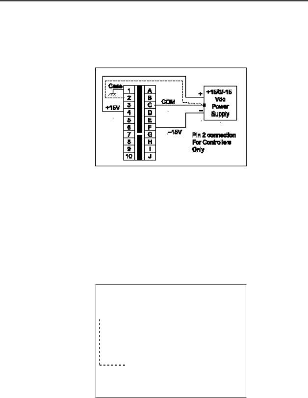
Wiring Transducers with 20-Pin Card-Edge Connectors Input
Power Connections
Figure 2-2. Input Power Connections (20-Pin Connector)
Output Signal Connections
Standard output for all transducers is a 0-5 VDC signal, which directly corresponds to the 0 to 100% mass flow full scale range. Output signals are linear and require a minimum load resistance of 1000 Ohms (4-20 mA output 600 Ohms maximum loop resistance).
The Auto-Trak 860 allows transmission of all available input/output signals to your computer’s RS-485 communications port (connection details are given below). For additional information, refer to the “AutoNet” Software Addendum included with this manual.
|
|
|
|
|
|
|
|
|
|
V or mA |
||
|
|
|
|
|
|
|
|
|
|
|
|
|
|
|
|
|
|
|
|
|
+ |
|
Panel Meter |
||
|
1 |
|
|
|
A |
|
|
|
PLC or |
|||
|
|
|
|
COM |
– |
|
||||||
V out+ |
2 |
|
|
|
B |
|
Recording |
|||||
|
|
|
|
|
|
|||||||
3 |
|
|
|
C |
|
|
|
|
Device |
|||
|
|
|
|
|
|
|
||||||
|
4 |
|
|
|
D |
|
|
|
|
|
|
|
|
5 |
|
|
|
E |
|
|
|
|
|
|
|
|
6 |
|
|
|
F |
|
|
|
|
|
|
|
|
7 |
|
|
|
G |
RS-485+ |
|
|
|
|
|
|
mA out+ |
8 |
|
|
|
H |
|
|
|
|
|
||
|
|
|
|
|
RS-485– |
|
|
COM:1 |
|
|
||
9 |
|
|
|
I |
|
|||||||
|
|
|
|
|
|
|||||||
|
10 |
|
|
|
J |
|
|
|
Computer |
|
||
RS-485 Communications
Model 860 ONLY
Figure 2-3. Output Signal Connections (20-Pin Connector)
Notes: 1. Controllers require a separate, dedicated ground wire between pin 2 and the power supply common to carry the valve coil current.
2.4-20 mA output signal is ground-referenced (“non-isolated”). Warning: Do NOT apply any external voltage to this loop.
IM-83/84/86-H |
2-7 |

Chapter 2 Installation |
Series 830/840/860 Instruction Manual |
|
|
Input Signal Connections (Controllers Only)
The 0-5 VDC (4-20 mA optional) set point command input signal allows you to set the flow to any desired value within the range of the controller. The set point input signal is a direct linear representation of 0 to 100 percent of the controller’s mass flow full scale value.
For 0–5 VDC set point control, connect a manual-adjust potentiometer as shown below. Any potentiometer value between 5K and 100K may be used but is limited to a VDC input signal only. For 4-20 mA set point control, use a 4-20 mA generator.
If the set point input is not connected to some type of control device, the valve on/off switch must be activated in the off position. If no set point command is present on the controller when powered-up and the valve is not switched off, the valve will drift wide open.
Figure 2-4.
Local Command Set Point Potentiometer (20-Pin Connector)
Figure 2-5.
External Command Set Point Source (20-Pin Connector)
Note: Use 15-volt maximum to produce a 4-20 mA setpoint signal.
2-8 |
IM-83/84/86-H |
Series 830/840/860 Instruction Manual |
Chapter 2 Installation |
|
|
Valve Purge and Valve Off Connections (Controllers Only)
Depending on the valve voltage, connect as shown below.
15 Volt Valve
|
COM |
|
1 |
|
|
|
A |
|
|
|
|
Purge |
|
|
|
On |
||||||||
|
|
|
|
2 |
|
|
|
B |
|
|
|
|
|
|
|
|
|
|
|
|
|
|
|
|
|
|
|
|
3 |
|
|
|
C |
|
|
|
|
|
|
|
|
|
|
|
|
|
|
|
Off |
|
|
|
|
|
|
|
|
|
|
|
|
|
|
|
|
|
|
|||||||
|
|
|
|
|
|
|
|
|
|
|
|
|
|
|
|
|
|
|
|
|
|
|
|
|
|
|
|
|
4 |
|
|
|
D |
|
|
|
|
|
|
|
|
|
|
|
|
|
|
|
|
|
|
|
|
|
|
|
|
|
|
|
|
|
|
|
||||||||||
|
|
|
|
5 |
|
|
|
E |
|
|
|
|
|
|
|
|
|
|
|
|
|
|
|
|
|
|
|
|
6 |
|
|
|
F |
|
|
|
|
|
|
|
|
|
|
|
|
|
|
|
|
|
|
|
|
7 |
|
|
|
G |
|
|
|
|
|
|
|
|
|
|
|
|
|
|
|
|
|
|
|
|
|
|
|
|
|
|
|
|
|
|
|
|
|
|
|
|
|
|
|||
|
|
|
|
8 |
|
|
|
H |
|
|
|
|
|
|
|
|
|
|
|
|
|
|
|
|
|
|
|
|
9 |
|
|
|
I |
|
Valve Off |
|
|
|
On |
||||||||||
|
|
|
|
10 |
|
|
|
J |
|
|
|
|
||||||||||||
|
|
|
|
|
|
|
|
|
|
|
|
|
|
|
|
|
|
|
|
|
|
|
||
|
|
|
|
|
|
|
|
|
|
|
|
|
|
|
|
|
|
|
|
|
|
|
|
|
|
|
|
Open collector output |
|
|
|
|
|
|
|
|
|
|
Off |
||||||||||
|
|
|
|
|
|
|
|
|
|
|
|
|
|
|
|
|
|
|
|
|
|
|
|
|
|
|
|
|
|
|
|
|
|
|
|
|
|
|
|
|
|
|
|
|
|
|
|
|
|
Figure 2-6.
Valve Purge and Valve Off (20-Pin Connector)
|
|
|
|
|
|
|
|
|
30 Volt Valve |
|
|
|
|
|
|
|
|
|
||||||||
|
|
|
|
|
|
|
|
|
|
|
|
|
|
|
|
|
|
|
|
|
|
|
|
|
|
On |
|
|
|
|
|
|
|
|
|
|
|
|
|
|
|
|
|
|
|
|
|
|
|
|
|
|
|
|
|
COM |
|
1 |
|
|
|
A |
Purge |
|
|
|
|
|
|
|
|
|
||||||||
|
|
|
|
|
|
|
|
|
|
|
||||||||||||||||
|
|
|
|
|
|
|
|
|
|
|
||||||||||||||||
|
|
|
2 |
|
|
|
B |
|
|
|
|
|
|
|
|
|
|
|
|
|
|
|
|
|
||
|
|
|
|
|
3 |
|
|
|
C |
|
|
|
|
|
|
|
|
|
|
|
|
|
|
|
|
Off |
|
|
|
|
|
|
|
|
|
|
|
|
|
|
|
|
|
|
|
|
|
|
|
|
|||
|
|
|
|
|
4 |
|
|
|
D |
|
|
|
|
|
|
|
|
|
|
|
|
|
|
|
|
|
|
|
|
|
|
|
|
|
|
|
|
|
|
|
|
|
|
|
|
|
|
|
|
|
|
||
|
|
|
|
|
|
|
|
|
|
|
|
|
|
|
|
|
|
|
|
|
||||||
|
|
|
|
|
5 |
|
|
|
E |
|
|
|
|
|
|
|
|
|
|
|
|
|
|
|
|
|
|
|
|
|
|
6 |
|
|
|
F |
|
|
|
|
|
|
|
|
|
|
|
|
|
|
|
|
|
+15V |
|
7 |
|
|
|
G |
|
|
|
|
|
|
|
|
|
|
|
|
|
|
|
|
|
|||
|
|
|
|
|
|
|
|
|
|
|
|
|
|
|
|
|
|
|
|
|||||||
|
8 |
|
|
|
H |
|
|
|
|
|
|
|
|
|
|
|
|
|
|
|
|
|
||||
|
|
|
|
|
|
|
|
|
|
|
|
|
|
|
|
|
|
|
|
|
|
|
|
|
||
|
|
|
|
|
9 |
|
|
|
I |
|
Valve Off |
|
|
|
|
|
|
|
|
On |
||||||
|
|
|
|
|
10 |
|
|
|
J |
|
|
|
|
|
|
|
|
|
||||||||
|
|
|
|
|
|
|
|
|
|
|
|
|
|
|
|
|
|
|
|
|
|
|
|
|
||
|
|
|
|
|
|
|
|
|
|
|
|
|
|
|
|
|
|
|
|
|
|
|
|
|
|
|
|
|
|
|
Open collector output |
|
|
|
|
|
|
|
|
|
|
|
Off |
||||||||||
|
|
|
|
|
|
|
|
|
|
|
|
|
|
|
|
|
|
|
|
|
|
|
|
|
|
|
|
|
|
|
|
|
|
|
|
|
|
|
|
|
|
|
|
|
|
|
|
|
|
|
|
|
|
|
|
|
|
|
|
|
|
|
|
|
|
|
|
|
|
|
|
|
|
|
|
|
|
|
|
|
Figure 2-7.Valve Purge and Valve Off (20-Pin Connector)
Note: Typically controllers for 10 slpm or below will be equipped with a 15-volt valve circuit, while those above 10 slpm with a 30-volt circuit. Consult Technical Support if necessary.
IM-83/84/86-H |
2-9 |
Chapter 2 Installation |
Series 830/840/860 Instruction Manual |
|
|
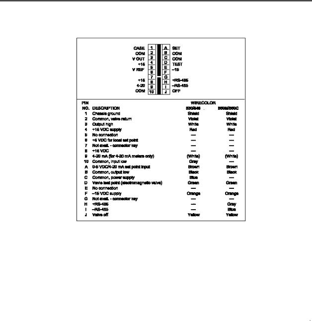
Figure 2-8. 20-Pin Connector Pin Designations
Note: Prior to 2001, sierra supplied separate cables for controllers and meters. These are now combined into one style for 830/840 devices and one style for 860M/C.
2-10 |
IM-83/84/86-H |
Series 830/840/860 Instruction Manual |
Chapter 2 Installation |
|
|
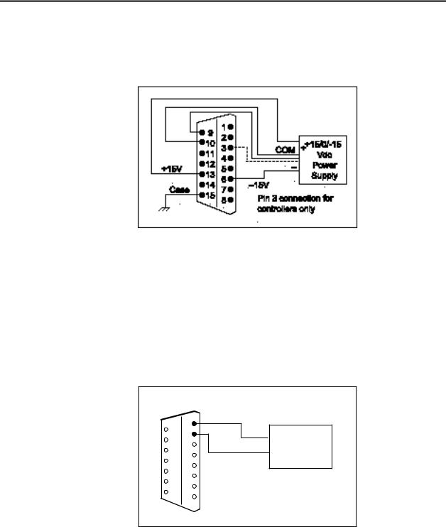
Wiring Transducers with 15-Pin D-Connectors
Input Power Connections
Figured 2-9. Input Power (15-Pin D-Connector)
Note: Use separate, dedicated wires for pins 9 and 10 to the power supply common on meters and pins 9,10 and 3 on controllers.
Output Signal Connections
Standard output for all transducers is a 0-5 VDC signal, which directly corresponds to the 0 to 100% mass flow full scale range. Output signals are linear and require a minimum load resistance of 1000 Ohms (4-20 mA output 600 Ohms maximum loop resistance).
|
1 |
COM |
|
V or mA |
9 |
|
– |
Panel Meter |
|
10 |
2 |
Output |
+ |
PLC or |
11 |
3 |
Recording |
||
4 |
|
|
||
12 |
|
|
Device |
|
13 |
5 |
|
|
|
6 |
|
|
|
|
14 |
7 |
|
|
|
15 |
8 |
|
|
|
Figure 2-10. Output Signal (15-Pin D-Connector) |
||||
Notes:
1.Panel meter or read-out device should be wired to be at the same ground potential as the power supply.
2.4-20 mA output signal is ground referenced (“non-isolated”). Warning: Do not apply any external voltage to this loop.
IM-83/84/86-H |
2-11 |
 Loading...