

Page 1

ACUSON X300 Ultrasound Imaging System
System Reference
10348704-VFT-001-01-01
Siemens Medical Solutions USA, Inc. 10348704 REV 01
Page 2

Software Version 3
Siemens Medical Solutions USA, Inc.
Ultrasound Division
1230 Shorebird Way
Mountain View, CA 94043-1344
U.S.A.
(800) 498-7948
(650) 969-9112
©2008 Siemens Medical Solutions USA, Inc.
All Rights Reserved.
February 2008
Printed in the Republic of Korea.
Siemens ACUSON X300, THI, MultiHertz, DIMAQ,
microCase, QuickSet, SuppleFlex, Evolve Package,
SynAps, TGO, DTI, 3-Scape, Axius, Clarify, SieClear,
SieScape, Velocity Vector Imaging, AcuNav, and
SwiftLink are trademarks or registered trademarks of
Siemens AG or its subsidiaries and affiliates.
Windows, CIDEX, CIDEX Plus, CIDEX OPA, Milton,
Virkon, STERRAD and Gigasept FF are registered
trademarks of their respective owners.
Siemens reserves the right to change system
specifications at any time.
CE Declaration
This product is provided with a CE marking in
accordance with the regulations stated in Council
Directive 93/42/EEC of June 14, 1993 concerning
Medical Devices. Siemens Medical Solutions USA,
Inc. is certified by Notified Body 0123 to Annex II.3 –
Full Quality System.
Authorized EC Representative:
Siemens Aktiengesellschaft
Medical Solutions
Henkestraße 127
D-91052 Erlangen
Germany
Page 3

Contents
Chapter 1 System Presets
Instructions for using the options in the Presets screen to customize the system.
Chapter 2 Documentation Devices
Information on documentation and storage devices, including procedures for
storing and retrieving system presets and QuickSets.
DICOM Connectivity Option Chapter 3
Explanation of the Digital Imaging and Communications in Medicine (DICOM)
Connectivity option. This option works in conjunction with the DIMAQ-IP integrated
workstation to provide digital image transfer using a DICOM network for both
storage and printing.
Chapter 4 Network Export Function
A description of setting up and using the network export function. This function
copies patient data to a password-protected shared folder on a destination device
(export host) for offline-analysis.
Chapter 5 Data Transmission Specifications
Guidelines for transmitting data from the ultrasound system through the serial ports
to a personal computer (PC).
Chapter 6 Cardiac References
Chapter 7 Obstetrical References
Note: Not all features and options described in this publication are available to all users. Please
check with your Siemens representative to determine the current availability of features and options.
SYSTEM REFERENCE i
Page 4

ii SYSTEM REFERENCE
Page 5

About the User and Reference Manuals
The user and reference manuals consist of the following publications.
Publication Includes
Instructions for Use Technical description of the ultrasound system
Safety and care information for the system and compatible transducers
Descriptions of all system controls
Procedures for system setup, examination fundamentals, and the biopsy
function
Acoustic output data
Features and Applications
Reference*
System Reference* Description of customizable system settings
Electromagnetic Emissions and
Immunity: Guidance and
Manufacturer's Declaration*
*Languages supported by the user interface include a translation of this publication.
Descriptions of image acquisition and optimization, including optional imaging
features
General and exam-specific measurements and calculations
Data management
Explanation of the clinical software programs for use on the ultrasound system
Information about DICOM connectivity, network capabilities, and external
devices
Clinical references
Information regarding the electromagnetic compatibility (EMC) testing of this
system
SYSTEM REFERENCE iii
Page 6
Conventions
Take a moment to familiarize yourself with these conventions.
Warnings, Cautions, and Notes
Cross-References
Customizable System Settings
Keys and Controls Keys and controls located on the control panel are identified by uppercase,
On-screen Objects On-screen objects such as menu selections, soft key selections, and buttons are
Selection of On-screen Objects
WARNING: Warnings are intended to alert you to the importance of
following the correct operating procedures where risk of injury to the patient
or system user exists.
Caution: Cautions are intended to alert you to the importance of following
correct operating procedures to prevent the risk of damage to the system.
Note: Notes contain information concerning the proper use of the system and/or
correct execution of a procedure.
Examples:
See also: Biohazards, Safety and Care, Chapter 2, Instructions for Use
See also: Documentation Devices, Chapter 2, System Reference
See also: Alphanumeric Keyboard, p. 26
System settings available for customization are depicted as shown.
Example:
Default Settings > Automatic Freeze Response
boldface type.
Example:
Rotate the 2D control.
Keys located on the keyboard are identified by boldface type.
Example:
Press the Exam key.
identified by boldface type.
Example:
The system displays the Patient Registration form.
The SET key on the control panel functions as a point-and-select device (similar
to a computer mouse) when used with the trackball.
"Select" or "click" describes this action:
Roll the trackball to position the pointer (cursor) on an on-screen object and then
press the SET key.
"Drag" describes this action:
Roll the trackball to position the pointer (cursor) on an on-screen object and then
press and hold the SET key. Roll the trackball to reposition the object and then
release the SET key.
iv SYSTEM REFERENCE
Page 7

1 System Presets
Setting General Preferences.............................................................................. 3
Using the System Presets .............................................................................3
Making Screen Selections...................................................................... 4
Presets Screen .............................................................................................. 5
General 1 — System Configuration Selections.............................................. 6
General 2 — System Configuration Selections.............................................. 7
Customizing the Sequence of Data Entry for the Patient Data Form...... 8
Peripheral — System Configuration Selections............................................. 9
Customize Keys — System Configuration Selections ................................... 9
Customizing the Display of Soft Key Selections................................... 12
Storage — System Configuration Selections............................................... 13
Display — System Configuration Selections................................................ 13
Exam Configuration — System Configuration Selections............................ 15
User-Defined Exam List — Exam Configuration Selections ........................16
Text Annotation — System Configuration Selections ..................................17
Customizing Text Annotations.............................................................. 18
Pictogram List — System Configuration Selections..................................... 20
Customizing Pictograms.......................................................................20
M & R Configuration 1 — Configuration Selections ..................................... 22
Customizing the Measurement and Report Preset Settings ................. 22
M & R Configuration 2 — Configuration Selections ..................................... 29
Summary — Configuration Selections......................................................... 29
Service — Serviceability Selections ............................................................ 30
Stress Echo — Options Selections.............................................................. 30
SieScape — Options Selections.................................................................. 31
DICOM — Options Selections ..................................................................... 31
DIMAQ Utility — Options Selections............................................................ 31
Clip Capture — Options Selections ............................................................. 32
Network Export — Options Selections......................................................... 32
Authorization ........................................................................................ 32
Archive .................................................................................................34
Printer — Options Selections....................................................................... 34
Customizing OB and Early OB Measurements, Calculations, and Reports 35
Item & Reference Selection, Standard OB ..................................................35
2D-Mode, M-Mode, Doppler, Ratio, and Growth Analysis Tabs........... 35
EFW / USMA Tab.................................................................................37
Item & Reference Selection, Early OB......................................................... 37
Display Item, Standard OB / Early OB......................................................... 37
Growth Analysis Graphs, OB and Early OB................................................. 38
Standard OB / Early OB User-Defined Formulas......................................... 39
Standard OB / Early OB User-Defined Tables............................................. 41
User-Defined Label, OB and Early OB ........................................................ 44
SYSTEM REFERENCE 1 - 1
Page 8

1 System Presets
Customizing Vascular Measurements, Calculations, and Reports .............. 45
Display Item — Cerebrovascular (C-Vascular)............................................ 45
Display Item — Peripheral Vascular (P-Vascular) ....................................... 46
Display Item — Venous ............................................................................... 46
Customizing Gynecology Measurements, Calculations, and Reports......... 47
Display Item — Gynecology ........................................................................47
Customizing Cardiac Measurements, Calculations, and Reports ................ 48
Measurement Order — Cardiac................................................................... 49
Heading Tab.........................................................................................49
Label Tab .............................................................................................49
Display Item — Cardiac............................................................................... 51
User-Defined Label — Cardiac....................................................................52
Customizing Emergency Medicine Measurements, Calculations, and
Reports ..............................................................................................................
Calculation Item — Emergency Medicine.................................................... 54
Customizing Fetal Echo Measurements, Calculations, and Reports........... 55
Display Item — Fetal Echo .......................................................................... 55
54
1 - 2 SYSTEM REFERENCE
Page 9

1 System Presets
Setting General Preferences
When the ultrasound system is installed at your site, all system settings are
factory-defined. You can use the options and settings available in the system presets
to set up the ultrasound system with your preferences for imaging. System presets
define the configuration of the system software whenever you power on the system.
Using the System Presets
You can use the system presets at any time to change the factory (default) settings or
modify your own presets.
Note: After powering on the system, you must wait until the system completes the series of
self-diagnostic and calibration tests before making any changes to the system presets. These
tests last a few minutes, after which the system presets are ready for use.
Siemens recommends that you back up your system presets and QuickSets onto
external storage media to prevent accidental loss of your information.
To use the system presets:
1. Press the Presets key on the keyboard.
The system displays the Presets screen, with menu items on the left and
selections on the right.
2. Roll the trackball to the required menu item on the left of the screen and then
press the SET key on the control panel.
The system displays selections for the selected menu item.
To save changes and exit the system presets:
Select the Save button at the bottom of the screen.
To discard changes and exit the system presets, choose a method:
Select the Cancel button at the bottom of the screen and then select No in the
displayed confirmation message.
Press the Presets key on the keyboard and then select No in the displayed
confirmation message.
SYSTEM REFERENCE 1 - 3
Page 10
1 System Presets
Making Screen Selections
Use the following techniques to make selections on the right of the Presets screen.
You can typically roll the trackball to position the trackball pointer on a menu item or
setting and then press the SET key to complete the selection.
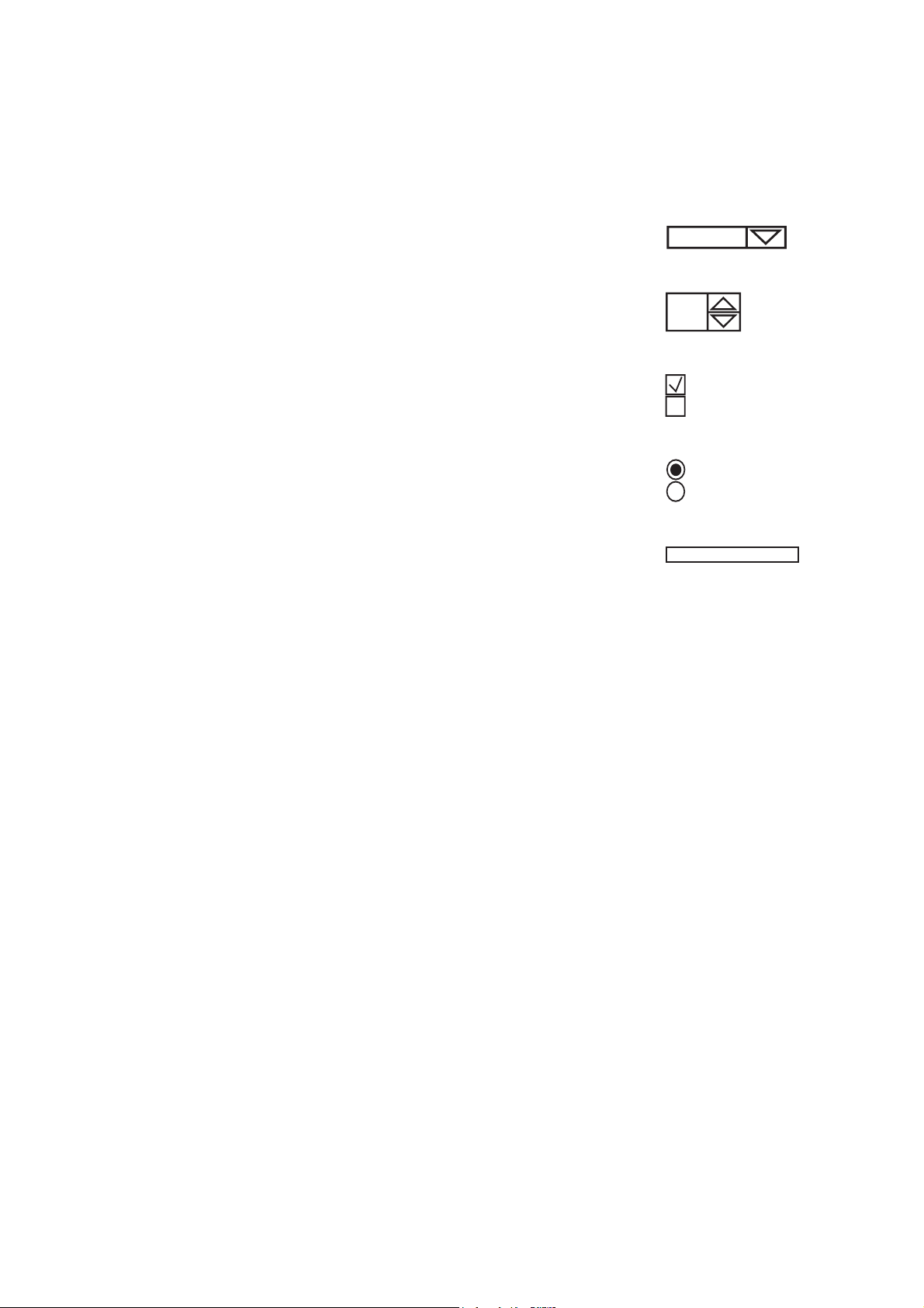
Drop-down menus – To open the menu, roll the trackball to position the
pointer on the arrow and then press the SET key. To make a selection,
roll the trackball to highlight the selection and then press the SET key.
Spin buttons – To set a higher or lower numeric value, roll the trackball
to position the pointer on the up or down arrow and press the SET key
until the desired value displays.
Check boxes – The option is selected when a checkmark displays
inside the box and de-selected when the box is clear. To select or clear
the check box, roll the trackball to position the pointer in the box and
then press the SET key.
Buttons – To select a labeled button, roll the trackball to position the
pointer on the button or the label and then press the SET key. In some
places, only one button can be selected at a time.
Text entry – Roll the trackball to position the cursor in the field and then
press the SET key. Use the keyboard to enter text. When finished, use
the Tab key to move to another field or roll the trackball to reposition the
cursor and then press the SET key.
Drop-down menu.
Spin button.
Check box.
Option button.
Text entry.
1 - 4 SYSTEM REFERENCE
Page 11

1 System Presets
Presets Screen
The left side of the Presets screen lists the following menu items:
Menu Item Allows you to...
General 1
General 2
Peripheral
Customize Keys Assign functionality to documentation controls, User-Defined keys, and the optional
Storage
Display
Exam Configuration
User-Defined Exam List
Text Annotation
Pictogram List
M & R Configuration 1
M & R Configuration 2
Summary
Service
Stress Echo Access a new screen. Displays the Maintenance dialog box, from which the system
SieScape
DICOM
DIMAQ Utility
Clip Capture
Network Export
Authorization
Archive
Printer
Enter the hospital name, establish date / time settings and format, designate height and
weight formats, and select the system monitor, audio, and boot-up settings.
Specify DGC settings, select the trackball speed, define information stored with
images, enable patient demographic display and storage, and select the library of
annotations for initial display.
Assign connections for the RS-232C (Serial) ports. Designate the video source and
hard copy video polarity.
footswitch.
Designate image and patient report storage formats, auto recall delay, and storage
destination.
Specify the automatic responses when the system is frozen or unfrozen and establish
Doppler and M-mode imaging settings.
Modify general settings for the selected exam type.
Enable or disable access to each exam type.
Customize annotation libraries for selected exam types or QuickSets.
Customize pictogram libraries for selected exam types or QuickSets.
Select caliper (measurement function) conventions and establish measurement and
report presets for each type of exam.
Select the number of heart cycles to be used when calculating the heart rate.
Customize page elements for the Summary report.
Access password-protected service procedures.
allows you to configure options for the optional Stress Echo feature.
Access a new screen. Specify settings for SieScape.
Configure the ultrasound system and connected devices (such as servers and printers)
for DICOM by creating, editing, and activating aliases (DICOM configurations).
Access password-protected disk utility procedures.
Designate clip capture parameters: capture type, clip length, R-wave delay, and JPEG
compression.
Verify selection of an existing setup, select another setup, edit an existing setup, or
create a new setup for the host or export host.
Manage accounts and passwords for access to DIMAQ study screens.
Configure archive deletion and save options.
Install and configure USB printers.
SYSTEM REFERENCE 1 - 5
Page 12

1 System Presets
General 1 — System Configuration Selections
The General 1 item on the Presets screen provides the following selections:
Selection Option(s) Allows you to...
Organization
Hospital Name
Format
Language English
Date Format Month / Day / Year
Date & Time
Settings
Height &
Weight Format
Audio
--- --text entry Enter the name of your hospital or clinic using up to
25 characters. You can modify this entry at any time.
--- --Designates the system language.
German
French
Spanish
Italian
Chinese
Russian
1
1
Select the format for the date. The selected format is used in the
Day / Month / Year
image screen, the Patient Data form, and the patient reports.
Year / Month / Day
--- Access a new screen. Enter the current date and time.
Metric
U.S.
Select the format for the display of the patient's height and
weight used in the Patient Data entry form.
--- ---
Beep on Key Press
Beep after Store
on, off Select this check box to enable the beep to sound when a key is
on, off Select this check box to enable the beep to sound when storage
Completes
Beep Volume 1 through 4,
in increments of 1
Line-in Volume Off, 1 through 25
Trackball Behavior
Trackball Travel
Speed
--- ---
Low
Medium
High
Annotation Type
--- ---
Default Type Anatomy
Position
Boot Up
--- ---
Active Transducer LC1
LC2
LC3
pressed.
is completed.
Set the volume of the beep. Option 1 is the quietest, Option 4 is
the loudest.
Adjusts the volume of video playback.
Select the responsiveness of the system to trackball movement.
Low repositions an object a short distance with minimal trackball
movement.
Medium repositions an object a moderate distance with minimal
trackball movement.
High repositions an object a long distance with minimal
trackball movement.
Specify the library initially displayed for the list of annotations on
the screen.
Select a linear or curved array transducer port to be active when
you power on the system.
1
Supported languages are dependent on regional availability.
1 - 6 SYSTEM REFERENCE
Page 13

1 System Presets
Selection Option(s) Allows you to...
Power Off Shutdown
Confirmation
Dialog
Power Off
Select the system response when the partial power on/off switch
(
) is pressed.
Shutdown Confirmation Dialog — Displays a confirmation
dialog box when powering off the system.
Power Off — Powers off the system directly.
General 2 — System Configuration Selections
The General 2 item on the Presets screen provides the following selections:
Selection Option(s) Allows you to...
Patient ID
AutoStore New
Patient Form
Hide Patient
Information
Customize Entry
Order…
Common Mode
Delete Pictogram on
Unfreeze
Delete Text on
Unfreeze
Default Annotation
Library
Pictogram Location Upper Right
Font Size 12, 14, 16, 18, 20
Arrow Size Small (Type1)
Patient Registration Original
Measurement Result
Display Size
--- ---
on, off Automatically store a screen representation of the completed
patient data form to the registered patient's study.
on, off Display or hide the patient demographic.
--- Access a new screen. Customize the order entry sequence in
the patient data form.
--- - - -
on, off Select this check box to erase an on-screen pictogram after an
image is unfrozen.
on, off Select this check box to erase on-screen text annotation after an
image is unfrozen.
On
Off
Displays the list of annotations on the screen when you activate
the annotation function.
Displays the pictogram at the selected screen location.
Lower Right
Select the point size of the font used for annotations.
Select the size and the type of the directional arrows used for
Small (Type2)
annotations.
Small (Type3)
Medium (Type1)
Medium (Type2)
Medium (Type3)
Large (Type1)
Large (Type2)
Large (Type3)
Original uses the standard patient registration form with
e-entry
conventional requirements for data entry and with modified
requirements for data entry:
Automatically entered year for History fields with OB,
Early OB, GYN, EM and Fetal Echo exam types (when month
and day are entered).
Editable fetal age (Age field for OB, Early OB, EM and
Fetal Echo exam types).
e-entry displays an overlay of patient identification fields on the
image screen.
Small
Select the size of display for the measured results.
Medium
Large
SYSTEM REFERENCE 1 - 7
Page 14

1 System Presets
Customizing the Sequence of Data Entry for the Patient Data Form
Note: This selection applies to the original patient data form only. To display an abbreviated patient
registration form, use the system presets to select the e-entry form.
During patient registration, pressing the Tab key on the keyboard moves the text
cursor to the beginning position of the next entry field in the patient data form. You
can change the order entry sequence by restricting the Tab key to move through only
the fields selected in the Customize Entry Order screen.
The Customize Entry Order screen has two columns: Selectable Entries on the left
(the factory-default is blank) and Entry Order on the right (the factory-default lists all
fields on the patient data form). The order of the entries in the Entry Order column
indicates the order of the cursor in the patient data form when the Tab key is pressed.
Although you can customize the movement of the Tab key through the fields on the
patient data form, the layout of the fields on the form is unchanged.
Note: You can use the trackball and SET key to move to any field on the patient data form.
To use the Customize Entry Order screen:
1. Press the Presets key on the keyboard to display the system presets and then
select General 2 from the left of the screen.
2. Select the Customize Entry Order from the right of the screen.
3. To remove a field from the Entry Order column, select the name of the field and
click Delete.
4. To remove all fields from the Entry Order column, click Delete All.
5. To insert a field from the Selectable Entries column, select the name of the field
and click Add.
6. To change the order of fields in the Entry Order column, select the name of the
field and click Move Up or Move Down.
7. To restore the factory default settings, select the Default button at the bottom of
the screen and then select the Yes button in the displayed message box to
confirm the action.
1 - 8 SYSTEM REFERENCE
Page 15

1 System Presets
Peripheral — System Configuration Selections
The Peripheral item on the Presets screen provides the following selections:
See also: Data Transmission Specifications, Chapter 5, System Reference
Note: The system does not allow identical options (except Off) for the External RS-232C Port #1
and the External RS-232C Port #2 selections. If you select an option for this selection (other than
Off) that is identical to the option currently selected for the External RS-232C Port #1 selection, then
the system sets the External RS-232C Port #1 selection to Off.
Selection Option(s) Allows you to...
Video
Video Format NTSC
Video Input Source Composite
External RS-232C
Port #1
External RS-232C
Port #2
VCR / DVR
Device Type Mitsubishi MD3000
Key Function Record / Pause
--- ---
PAL
S-VHS
Off
PC2
VCR / DVR
Color Printer
Off
PC2
VCR / DVR
Color Printer
--- ---
JVC BD-X201
None
Record / Stop
Select the video format for output to the onboard printer.
Assign video input functionality.
Composite: Black and white video source
S-VHS: Color video source.
Assign functionality to the serial port on the input / output
panel of the ultrasound system.
PC2 enables data transmission through the serial port to
an external personal computer (PC) or a workstation.
VCR / DVR enables the video recording device.
Color Printer enables the color printer.
Assign functionality to the serial port on the input / output
panel of the ultrasound system.
PC2 enables data transmission through the serial port to
an external personal computer (PC) or a workstation.
VCR / DVR enables the video recording device.
Color Printer enables the color printer.
Select the VCR / DVR device.
Assign functionality to the VCR / DVR key.
Customize Keys — System Configuration Selections
The Customize Keys item on the Presets screen provides the following selections:
Selection Option(s) Allow you to…
Key Direction
Depth CW
Zoom CW
Focus CW
--- ---
CCW
CCW
CCW
Assign the direction of rotation to the DEPTH control for
increasing the depth. (CW = Clockwise, CCW =
Counterclockwise)
Assign the direction of rotation to the ZOOM control for
increasing the magnification factor. (CW = Clockwise,
CCW = Counterclockwise)
Assign the direction of rotation to the FOCUS control for
decreasing the depth of the focal zone marker (to the
near field). (CW = Clockwise, CCW = Counterclockwise)
SYSTEM REFERENCE 1 - 9
Page 16

1 System Presets
Selection Option(s) Allow you to…
Key Function
--- ---
Soft Menu Customize… Access a new screen. Displays the Soft Menu screen,
from which the system allows you to customize the
display of soft key selections.
Print/Store 1 Key B/W Print
Color Print
PC Printer
USB B/W
USB Color Disk Store
Volume Store
Clip Capture
DICOM B/W Print
Assign functionality to the PRINT/STORE1 key.
Note: The selections for USB printers (for example,
PC Printer or Disk Store & USB B/W) are available
when you select a USB printer (located in the Printer
section of the Printer presets screen).
DICOM Color Print
Disk Store & B/W Print
Disk Store & Color Print
Disk Store & PC Printer
Disk Store & USB B/W
Disk Store & USB Color
Print/Store 2 Key B/W Print
Color Print
PC Printer
USB B/W
USB Color
Disk Store
Volume Store
Clip Capture
Assign functionality to the PRINT/STORE2 key.
Note: The selections for USB printers (for example,
PC Printer or Disk Store & USB B/W) are available
when you select a USB printer (located in the Printer
section of the Printer presets screen).
DICOM B/W Print
DICOM Color Print
Disk Store & B/W Print
Disk Store & Color Print
Disk Store & PC Printer
Disk Store & USB B/W
Disk Store & USB Color
Clip Store Key Disk Store
Assign functionality to the CLIP STORE key.
Volume Store
Clip Capture
Left Pedal Freeze
B / W Print
Color Print
Disk Store
Clip Capture
Rotate 90° Clockwise
(TEE)
Rotate 90° Counter
Assign functionality to the left pedal of the optional
footswitch.
Note: The selections for USB printers (for example,
PC Printer or Disk Store & USB B/W) are available
when you select a USB printer (located in the Printer
section of the Printer presets screen).
Clockwise (TEE)
Caliper
Update/View
Escape/Timer
4B
Split
TGO Update
U/D Flip
L/R Flip
USB B/W
USB Color
1 - 10 SYSTEM REFERENCE
Page 17

1 System Presets
Selection Option(s) Allow you to…
Right Pedal Freeze
B / W Print
Color Print
Disk Store
Clip Capture
Rotate 90° Clockwise
(TEE)
Rotate 90° Counter
Clockwise (TEE)
Caliper
Update/View
Escape/Timer
4B
Split
TGO Update
U/D Flip
L/R Flip
USB B/W
USB Color
User-Defined 1 Key 4B
Split
Sector
U / D Flip
L / R Flip
Full Size
Full D
Full M
Dir Power
ECG
Exam
Report
Graph
Arrow
Clip Capture
Biopsy
Volume Store
Clarify VE
None
User-Defined 2 Key 4B
Split
Sector
U / D Flip
L / R Flip
Full Size
Full D
Full M
Dir Power
ECG
Exam
Report
Graph
Arrow
Clip Capture
Biopsy
Volume Store
TGO Update
Clarify VE
None
Assign functionality to the right pedal of the optional
footswitch.
Note: The selections for USB printers (for example,
PC Printer or Disk Store & USB B/W) are available
when you select a USB printer (located in the Printer
section of the Printer presets screen).
Assign functionality to the USER DEFINE 1 key.
Assign functionality to USER DEFINE 2 key.
SYSTEM REFERENCE 1 - 11
Page 18

1 System Presets
Selection Option(s) Allow you to…
NEW Key Not Used
Close Study
Close Study and reload
boot-up setting
Exchange Key
Functionality
Exchange
Functionality of Set
and Escape key
--- ---
on, off
Select the system response when the NEW key is
pressed.
Not Used disables the NEW key.
Close Study closes the current study.
Close Study and reload boot-up setting closes the
current study and resets the system with the boot-up
setting.
Exchange the functionality of the SET key and
ESCAPE key on the control panel.
Customizing the Display of Soft Key Selections
You can rearrange or remove the soft key selections available for the following modes
of operation:
2D-mode
Color Flow
Power
M-mode
Doppler
3D imaging
Each mode has a tab for real-time imaging selections (Live [Lv]) and a tab for system
freeze selections (Frz). Each tab has multiple "pages" of soft key selections. The soft
key selections are represented as buttons on the Soft Menu screen in the system
presets.
Note: An asterisk (*) indicates there are unsaved changes on a tab.
To remove soft key selections from buttons:
1. To remove a single soft key selection:
a. Select the button representing the soft key selection.
The system displays a drop-down list of available options below the selected
button.
b. Select Blank.
Blank displays on the selected button.
2. To remove a page of soft key selections, select the << or >> button to access the
page and then select the Delete Page button.
The system removes the labels from all buttons on the page.
3. To remove a tab of soft key selections, select the Delete All button.
The system removes the labels from all buttons on all pages of the tab.
1 - 12 SYSTEM REFERENCE
Page 19

1 System Presets
To assign a new soft key selection to a button:
1. Select the required button representing the soft key selection.
The system displays a drop-down list of available options below the selected
button.
2. Select the required label.
The button displays the new soft key option.
3. Repeat steps 1 and 2 as required.
To reset the soft key selections to factory default settings:
Select the Default button at the bottom of the screen and then select the
Yes button in the displayed message box to confirm the action.
Storage — System Configuration Selections
The Storage item on the Presets screen provides the following selections:
Selection Option(s) Allows you to…
Image Store
Image Store Format TIFF (tagged-image
--- ---
file format)
Select the format for storing the image and patient data to
the disk drive.
Note: This selection indicates the image store format used
by the system.
Image Store Format
with Caliper
Size Full Screen (1024x768)
on, off Select whether to store caliper (measurement) information
with the image.
Selects the storage size of the image screen.
Diagnostic Window
Only (800x600)
Display — System Configuration Selections
The Display item on the Presets screen provides the following selections:
Selection Option(s) Allows you to…
Monitor
Enable Screen
Saver
Screen Saver Delay 5
Screen Saver Type Black
Display
Video Invert
--- --on, off Select this check box to activate or uncheck to deactivate
10
15
20
SIEMENS
--- --on, off Select the polarity of the video display for the main image
the screen saver.
Select the time delay (in minutes) before the system
activates the screen saver.
Select the background for the screen saver.
screen. Text is always white against gray or gray against
white.
On (checked) displays a white image area against a black
background.
Off (cleared) displays a black image area against a white
background.
SYSTEM REFERENCE 1 - 13
Page 20

1 System Presets
Selection Option(s) Allows you to…
DGC
DGC Invert with
Image Invert
DGC Curve Display Off
--- --on, off Select this check box to invert the DGC graphic on the
image screen when you rotate the image.
Select when the DGC graphic displays on the image screen.
Always On
Time Out
Off prevents the DGC from displaying on the image screen.
Always On displays the DGC continuously on the
image screen.
Time Out removes the DGC from the screen three seconds
after you adjust the curve. When you adjust the
DGC controls again, the curve reappears on-screen.
DGC Control Max image depth
Select the image depth setting.
Current image depth
Thermal Index
Display(Neo Head
Exam only)
Doppler / M-Mode
Bypass M / D
Cursor Display
TIS / TIB
TIC
Select whether to display TIS / TIB (Soft Tissue Thermal
Index / Bone Tissue Thermal Index) or TIC (Cranial Bone
Thermal Index) during neonatal head exams.
--- --on, off
Select the system response when the M or D control is
pressed. Select this check box to immediately display
M-mode or Doppler. De-select the check box to initially
display an M-mode or Doppler cursor in the 2D-mode
image; the M or D control must then be pressed a second
time for M-mode or Doppler to display.
Doppler
Search Mode
on, off Select this check box to activate Doppler Search Mode by
pressing the D control, and audibly interrogate vessels with
Doppler in 2D-mode before displaying the Doppler
spectrum.
Doppler Frequency /
Velocity
Frequency
Velocity
Display frequency (Hz) or velocity (cm/s) as a unit in the
Doppler spectrum.
1 - 14 SYSTEM REFERENCE
Page 21

1 System Presets
Exam Configuration — System Configuration Selections
The Exam Configuration item on the Presets screen provides the following
selections:
Selection Option(s) Allows you to...
Exam Abdomen
OB
Early OB
GYN
MSK
Breast
Thyroid
Testicle
Urology
Cardiac
Orthopedic
P-Vascular
C-Vascular
Venous
Renal
Fetal Echo
Ped Abd
Ped Echo
Penile
Neo Head
Sup MSK
TCD
Digital
EM
Small Parts
OB(J)
TEE
Automatic Freeze
Response
Caliper
Arrow
Text
Cine
Pictogram
Seamless Dual On
Off
Steer Angle Type
(VF10-5 Only)
2D/M & 2D/Doppler
Display Format
FOV-1
FOV-2
1/2 2D – 1/2 trace
1/3 2D – 2/3 trace
2/3 2D – 1/3 trace
Side by side
Default Doppler
Update Style
2D-Frz / D-Lv
2D-Lv / D-Lv
D-Lv / 2D-1s
D-Lv / 2D-2s
D-Lv / 2D-4s
D-Lv / 2D-8s
D-Lv / 2D-EOS
Select an exam for customization.
Select the system response when the FREEZE key is
pressed. Cine activates the CINE function. Caliper activates
the measurement function.
Text activates the annotation function. Arrow activates the
arrow function.
Activate seamless display of dual and split images.
Specify the steering angle for the VF10-5 transducer.
Specify the image screen layout when two imaging modes
are active.
1/2 2D – 1/2 trace presents 2D-mode on the right side of the
upper 1 / 2, with M-mode or Doppler in the lower 1/2.
1/3 2D – 2/3 trace presents 2D-mode on the right side of the
upper 1 / 3, with M-mode or Doppler in the lower 2/3.
2/3 2D – 1/3 trace presents 2D-mode on the right side of the
upper 2/3, with M-mode sweep or Doppler spectrum in the
lower 1/3.
Side by side presents 2D-mode in the left 40 percent of the
screen and either the M-mode sweep or the Doppler
spectrum in the right 60 percent of the screen.
Select display of real-time 2D image during update or select
the update interval for the 2D image during update.
The update interval for D-Lv / 2D-EOS is the end of the
sweep.
SYSTEM REFERENCE 1 - 15
Page 22

1 System Presets
Selection Option(s) Allows you to...
Linear Steer Color
Invert
Auto Invert of Color
and Spectrum
On
Off
On
Off
Select On to automatically invert the color velocity scale
when you steer the ROI.
Select On to invert the Doppler spectrum and the color bar
together in 2D-mode with Color / Doppler when the
INVERT key is pressed.
2D-Mode Steer with
Cursor
Physio Management
ECG Display
On
Off
Select On to allow the 2D-mode display to be steered by
moving the Doppler cursor.
--- --on, off Select this check box to display the related trace when the
selected exam is activated. ECG trace displays from the
ECG input.
Indicate R-Wave
on, off Select this check box to identify R-wave triggers in CINE
and also to indicate poor detection of an R-wave.
Auto FOV with Color
Activation
On
Off
Automatically adjust the 2D-mode field of view (FOV) to the
color region of interest (ROI).
User-Defined Exam List — Exam Configuration Selections
The User-Defined Exam List item on the Presets screen provides the following
selections:
Note: The currently activated exam is unavailable (dithered). The default exam for each transducer
will continue to display in the Exam list when an exam is de-selected in the User-Defined Exam List
screen.
Selection Option(s) Allows you to...
Enable Exam
Abdomen
OB
Early OB
GYN
MSK
Breast
Thyroid
Testicle
Urology
Cardiac
Orthopedic
P-Vascular
C-Vascular
Venous
Renal
Fetal Echo
Ped Abd
Ped Echo
Penile
Neo Head
Sup MSK
TCD
Digital
EM
Small Parts
OB(J)
TEE
--on, off
on, off
on, off
on, off
on, off
on, off
on, off
on, off
on, off
on, off
on, off
on, off
on, off
on, off
on, off
on, off
on, off
on, off
on, off
on, off
on, off
on, off
on, off
on, off
on, off
on, off
on, off
Customize the list of available exams for some items in the
Presets screen.
1 - 16 SYSTEM REFERENCE
Page 23

1 System Presets
Text Annotation — System Configuration Selections
The Text Annotation item on the Presets screen provides the following selections
(below the title Customize Text Annotation):
Selection Option(s) Allows you to...
Exam & QuickSet Abdomen
Text Annotation Anatomy
(text box) --- Enter a user-defined annotation or change the selected
Modify
Add
Delete
Move Up
Move Down
OB
Early OB
GYN
MSK
Breast
Thyroid
Testicle
Urology
Cardiac
Orthopedic
P-Vascular
C-Vascular
Venous
Renal
Fetal Echo
Ped Abd
Ped Echo
Penile
Neo Head
Sup MSK
TCD
Digital
EM
Small Parts
OB(J)
TEE
Position
--- Replace the selected annotation with the characters
--- Insert the annotation that is displayed in the text box into
--- Remove the annotation that is displayed in the text box
--- Shift the selected annotation to the next highest position
--- Shift the selected annotation to the next lowest position
Select an exam type or QuickSet for customization.
Display the selected list (library) of annotations.
annotation.
displayed in the text box.
the displayed list (library).
from the displayed list (library).
within the list (library).
within the list (library).
SYSTEM REFERENCE 1 - 17
Page 24

1 System Presets
Customizing Text Annotations
Each exam type has a list of text annotations for anatomical structures and body
positions.
You can display a library of annotations for an exam type or QuickSet, use the scroll
bar to display additional selections, insert, edit, and remove annotations, change the
position of annotations within the library, and reset the annotation library to factory
defaults.
To display a library of annotations for an exam type or QuickSet:
1. Press the Presets key on the keyboard to display the system presets and then
select Text Annotation from the left of the screen.
The system displays the Customize Text Annotation screen.
2. Select the exam type or QuickSet from the Exam & QuickSet drop-down list.
3. To exit the system presets without saving changes, select the Cancel button at
the bottom of the screen and then select No to confirm the action.
To display additional selections when a scroll bar is displayed:
1. Roll the trackball to the up or down arrow on the scroll bar to the right of the
selections and press and hold the SET key.
2. Roll the trackball until the required selections are displayed and then release the
SET key.
To insert an annotation into the displayed library:
1. To specify the location for the new annotation, select an existing annotation within
the library.
The system highlights the selected annotation and displays the annotation in the
text box.
2. Use the keyboard to delete the text in the text box and then enter the new
annotation into the text box.
Note: You can enter up to 25 characters.
3. Select the Add button.
The system inserts the new annotation below the selected existing annotation
within the library.
4. To save changes and exit the system presets, select the Save button at the
bottom of the screen.
1 - 18 SYSTEM REFERENCE
Page 25

1 System Presets
To edit an annotation in the displayed library:
1. Select the annotation within the library.
The system highlights the selected annotation and displays the annotation in the
text box.
2. Use the keyboard to edit the annotation in the text box.
3. Select the Modify button.
The system replaces the selected annotation with your edits.
4. To save changes and exit the system presets, select the Save button at the
bottom of the screen.
To remove an annotation from the displayed library:
1. Select the annotation within the library.
The system highlights the selected annotation and displays the annotation in the
text box.
2. Select the Delete button.
3. To save changes and exit the system presets, select the Save button at the
bottom of the screen.
To change the position of an annotation within the displayed library:
1. Select the annotation within the library.
The system highlights the selected annotation and displays the annotation in the
text box.
2. To shift the annotation to the next highest position within the library, select the
Move Up button.
3. To shift the annotation to the next lowest position within the library, select the
Move Down button.
4. To save changes and exit the system presets, select the Save button at the
bottom of the screen.
To reset annotations for the selected exam type or QuickSet to factory defaults:
Select the Default button at the bottom of the screen and then select the
Yes button in the displayed message box to confirm the action.
SYSTEM REFERENCE 1 - 19
Page 26

1 System Presets
Pictogram List — System Configuration Selections
The Pictogram List item on the Presets screen provides the following selections
(below the title Customize Pictogram List):
Selection Option(s) Allows you to...
Exam & QuickSet Abdomen
All Pictograms
Selected
Add
Delete
Move Up
Move Down
OB
Early OB
GYN
MSK
Breast
Thyroid
Testicle
Urology
Cardiac
Orthopedic
P-Vascular
C-Vascular
Venous
Renal
Fetal Echo
Ped Abd
Ped Echo
Penile
Neo Head
Sup MSK
TCD
Digital
EM
Small Parts
OB(J)
TEE
--- Display the pictograms available on the system.
--- Display the library of pictograms for the selected
--- Insert the selected pictogram into the displayed
--- Remove the selected pictogram from the displayed
--- Shift the selected pictogram to the next highest
--- Shift the selected pictogram to the next lowest
Select an exam type or QuickSet for customization.
exam type or QuickSet.
library.
library.
position within the library.
position within the library.
Customizing Pictograms
Each exam type has pictograms that can be selected when the exam type is active.
The pictograms are stored in libraries that you can edit for each exam type. The first
available pictogram in the library displays on the screen when you press the
PICTOGRAM key on the control panel.
You can display the library of pictograms for an exam type or QuickSet, use the scroll
bar to display additional selections, insert and remove pictograms, change the
position of pictograms within the library, and reset the pictogram library to factory
defaults.
1 - 20 SYSTEM REFERENCE
Page 27

1 System Presets
To display the library of pictograms for an exam type or QuickSet:
1. Press the Presets key on the keyboard to display the system presets and then
select Pictogram List from the left of the screen.
The system displays the Customize Pictogram List screen.
2. Select the exam type or QuickSet from the Exam & QuickSet drop-down list.
3. To exit the system presets without saving changes, select the Cancel button at
the bottom of the screen and then select No to confirm the action.
To display additional selections when a scroll bar is displayed:
1. Roll the trackball to the up or down arrow on the scroll bar to the right of the
selections and press and hold the SET key.
2. Roll the trackball until the required selections are displayed and then release the
SET key.
To insert a pictogram into the displayed library:
1. Select the new pictogram from the All Pictograms section of the screen.
2. Select the Add button.
The system places the new pictogram at the bottom of the list in the Selected
section of the screen.
3. To save changes and exit the system presets, select the Save button at the
bottom of the screen.
To remove a pictogram from the displayed library:
1. Select the pictogram from the Selected section of the screen.
The system outlines the selected pictogram.
2. Select the Delete button.
3. To save changes and exit the system presets, select the Save button at the
bottom of the screen.
To change the position of a pictogram within the displayed library:
1. Select the pictogram from the Selected section of the screen.
The system outlines the selected pictogram.
2. To shift the pictogram to the next highest position within the library, select the
Move Up button.
3. To shift the pictogram to the next lowest position within the library, select the
Move Down button.
4. To save changes and exit the system presets, select the Save button at the
bottom of the screen.
To reset pictograms within the displayed library to factory defaults:
Select the Default button at the bottom of the screen and then select the
Yes button in the displayed message box to confirm the action.
SYSTEM REFERENCE 1 - 21
Page 28

1 System Presets
M & R Configuration 1 — Configuration Selections
The M & R Configuration 1 item on the Presets screen provides the following
selections:
Selection Option(s) Allows you to…
Measurement and
Report Preset
Report Data Auto
Store
(Drop-down list)
--- ---
on, off Select the check box to automatically store the patient report and
Abdomen
OB
Early OB
GYN
MSK
Breast
Thyroid
Testicle
Urology
Cardiac
Orthopedic
P-Vascular
C-Vascular
Venous
Renal
Fetal Echo
Ped Abd
Ped Echo
Penile
Neo Head
Sup MSK
TCD
Digital
EM
Small Parts
OB(J)
TEE
measurement data to the DIMAQ-IP integrated workstation when
studies are ended.
Change measurement and report settings for the selected
exam type.
Customizing the Measurement and Report Preset Settings
The Measurement and Report Preset section allows you to customize each exam
type.
Measurement Method
(For use with all exam types)
Use this selection to establish a shortcut to a specific measurement method.
The upper section of this screen allows you to select the method activated when the
system first enters the measurement function for the specified imaging mode.
The lower section of this screen allows you to select a specific method for automatic
activation when a general measurement method is selected in the measurement
function. For example, if Ellipse is selected in the Area field, selecting Area from the
list of general measurement methods automatically activates the Ellipse method.
1 - 22 SYSTEM REFERENCE
Page 29

1 System Presets
To select the Default Measurement Method by Mode:
1. For each imaging mode, roll the trackball to the arrow on the right side of the
method field and then press the SET key.
The system displays a pull-down menu of available measurement methods for
this imaging mode.
2. Roll the trackball to highlight a measurement method and then press the SET key.
The highlighted method becomes the default for this imaging mode.
To select the Default Measurement Method:
1. For each measurement method category, roll the trackball to the arrow on the
right side of the method field and then press the SET key.
The system displays a pull-down menu of specific methods.
2. Roll the trackball to highlight a measurement method and then press the SET key.
The highlighted method becomes the default for this method category.
Customize Keys
(For use with all exam types)
You can customize the display of soft key selections for use during the measurement
function for the following modes:
2D-mode
M-mode
Doppler
See also: Customizing the Display of Soft Key Selections, p. 1-12
SYSTEM REFERENCE 1 - 23
Page 30

1 System Presets
General Configuration
(For use with all exam types)
Selection Option(s) Allows you to…
General Caliper
Caliper Default
Position
Caliper Pattern x
Caliper Size Small
Measurement
Results Background
Measurement Result
Display
2D-Mode Top
Doppler/M-Mode Top
--- Change general settings that apply to all exam types.
Center
Menu
Depth
+
Medium
Large
On
Off
--- ---
Bottom
Left
Right
Bottom
Left
Right
Assign trackball control to the pointer or measurement marker when
the measurement function is initiated.
Center displays the first marker in the center of the image screen. A
depth value does not display.
Menu displays the trackball pointer in the Measurement Menu if a
label is available. For exam types with no labels, the trackball pointer
remains in the center of the image screen when Menu is selected.
Depth displays the first marker in the center of the image screen,
with a dotted line representing the depth from the skin line. A depth
value displays in the Measured Results area of the image screen
until you anchor the first marker.
Specify the shape of the caliper. You can specify one shape at a
time for the entire system. Multiple measurements use the same
shape, but are differentiated by number.
Specify the size of the caliper for use by the entire system. A smaller
size may make a larger number of calipers easier to view.
Activate or deactivate a background for the Measured Results
section of the image screen.
Displays the Measured Results at the selected screen location in
2D-Mode.
Displays the Measured Results at the selected screen location in
Doppler or M-Mode.
Measurement Order
(For use with the following exam types only: GYN, P-Vascular, C-Vascular, Fetal Echo, Penile, TCD,)
Use this selection to add and delete labels and to rearrange the order in which labels
appear in the Measurement Menu. The Measurement Order screen presents two
columns of entries: Selectable Label on the left and Measurement Order on the
right. Add labels from left to right or delete labels from right to left. User-defined labels
initially appear on the left.
To select an imaging mode (GYN, Fetal Echo, TCD exam types only):
Roll the trackball to the down arrow for the Mode drop-down menu, select the
required imaging mode and then press the SET key.
1 - 24 SYSTEM REFERENCE
Page 31

1 System Presets
To add labels:
1. Roll the trackball to a selectable label on the left and then press the SET key.
The system highlights the label.
2. Roll the trackball to the Add button and then press the SET key.
The label is moved to the bottom of the Measurement Order list on the right.
3. Repeat steps 1 and 2 for other labels, as required.
To delete labels:
1. Roll the trackball to a label in the Measurement Order list on the right and then
press the SET key.
The system highlights the label.
2. Roll the trackball to the Delete button and then press the SET key.
The label is moved to the bottom of the Selectable Label list on the left.
3. Repeat steps 1 and 2 for other labels, as required.
To rearrange labels:
1. Roll the trackball to one of the labels in the Measurement Order list on the right
and then press the SET key.
The system highlights the label.
2. Roll the trackball to the Move Up or Move Down button and then press the
SET key.
The label moves up or down one space in the list.
3. Repeat steps 1 and 2 as required to create a restructured Measurement Order
list.
To reset labels back to factory default positions:
1. Roll the trackball to the Default button and then press the SET key.
The system prompts you to confirm your choice.
2. Roll the trackball to the Yes button and then press the SET key to continue.
SYSTEM REFERENCE 1 - 25
Page 32

1 System Presets
Follicle Measurement Method – Gynecology Exam
The gynecology exam Measurement Order screen contains an extra field for
specifying the Follicle Measurement Method.
To select the Follicle Measurement Method (Gynecology exam):
1. Roll the trackball to the arrow on the right of the Follicle Measurement Method
field and then press the SET key.
The system displays a drop-down menu of available selections.
2. Roll the trackball to highlight one of the selections and then press the SET key.
The highlighted selection becomes the new Follicle Measurement Method.
LV (Left Ventricle) Measurement Method – Fetal Echo Exam
The fetal echo exam Measurement Order screen contains an extra field for
specifying the LV Measurement Method.
To select the LV Measurement Method (Fetal Echo exam):
1. Roll the trackball to the arrow on the right of the LV Measurement Method field
and then press the SET key.
The system displays a drop-down menu of available selections.
2. Roll the trackball to highlight one of the selections and then press the SET key.
The highlighted selection becomes the new LV Measurement Method.
Display Item
(For use with the following exam types only: Urology, Orthopedic, Emergency Medicine, Penile, TCD)
Use this selection to control display of various items on the measurement screen and
in the patient report. The Display Item screen is unique for each exam type.
Selection Option(s) Allows you to...
Measurement Screen
Abbreviated Display
of Results
Hip Angle Graph
(Ortho exam only)
Report
Performing MD
Referring MD
--- --on, off Select this check box to display only labels with assigned measurement
values in the Measured Results. De-select the check box to display all
labels on the Measurement Menu in the Measured Results.
on, off Select this check box to display the sonographic hip angle graph when an
Ortho exam measurement has been completed.
--- --on, off Select this check box to include the Performing MD entered in the Patient
Data form at the bottom of the report page.
on, off Select this check box to include the Referring MD name entered in the
Patient Data form at the bottom of the report page.
1 - 26 SYSTEM REFERENCE
Page 33

1 System Presets
User-Defined Label
(For use with the following exam types only: GYN, P-Vascular, C-Vascular)
Use this selection to designate special measurement labels.
See also: User-Defined Label, OB and Early OB, p. 1-44
See also:
User-Defined Label — Cardiac, p. 1-52.
To create a user-defined label:
1. Roll the trackball to the NAME field and then press the SET key.
2. Use the keyboard to type in a label name.
3. Select a required measurement method from the drop-down list.
Note: Measurement method selection is available for the GYN exam only.
4. Repeat steps 1 through 3 for each label.
5. When all labels have been entered, roll the trackball to the Save button and then
press the SET key.
Note: For user-defined labels to appear in the Measurement Menu, you must add them to the
Measurement Order list using the Measurement Order screen.
To delete a user-defined label:
Click Delete Label.
User-Defined Formula
(For use with the following exam types only: P-Vascular, C-Vascular)
See also:
Standard OB / Early OB User-Defined Formulas, p. 1-39.
To create a user-defined formula:
1. From the Measurement and Report Preset selections for the C-Vascular or
P-Vascular exam, roll the trackball to the User-Defined Formula button and then
press the SET key.
The system displays the User-Defined Formula screen.
2. Roll the trackball to the first field and then press the SET key.
3. Use the keyboard to enter up to eight characters as the name for the formula.
4. Enter the formula in the field below the formula name. Use the keyboard to enter
any of the numbers and operators shown in the Operation box at the bottom of
the screen.
5. Roll the trackball to any of the Variable Labels on the right and then press the
SET key to include the variable in the formula.
6. Define constants by first rolling the trackball to the Value field to the right of the
constant label letter and then pressing the SET key.
7. Enter a numeric value of up to eight characters, including a decimal point if
required and then press the Enter key on the keyboard.
SYSTEM REFERENCE 1 - 27
Page 34

1 System Presets
8. To insert a constant into a formula, roll the trackball to the appropriate letter in the
Label column and then press the SET key.
The system inserts the label letter into the formula.
Note: You can use parentheses, but do not use spaces to separate elements in your formula.
Do not delete any of the quote marks entered by the system. You can enter up to 64 characters
in the formula field. To conserve space, you can assign a letter value to a constant and enter the
letter into your formula instead of the full constant.
9. For additional formulas, roll the trackball to a different formula tab and then press
the SET key. Repeat steps 2 through 8.
To delete a user-defined formula:
Roll the trackball to the Delete Formula button and then press the SET key.
The system deletes the formula for this tab.
To exit the User-Defined Formula screen:
1. To exit and save the formula, roll the trackball to the Save button and then press
the SET key.
The system informs you if there is a syntax or other error in the formula. Resolve
the problem and exit again.
2. To exit and not save the formula, roll the trackball to the Previous button and
then press the SET key.
The system queries you to save changes by selecting Yes or discard changes by
selecting No.
Comments Library for Report
(For use with the following exam types only: OB, Early OB, GYN, Urology, Cardiac, Orthopedic,
P-Vascular, C-Vascular, Venous, Ped Echo, Penile, TCD, EM, TEE)
For exam types with reports, you can enter ten comments for automated inclusion into
the report. A maximum of 256 characters is allowed per comment.
Creating a library of comments for a patient report saves you time, particularly for
recurring examinations. Rather than entering a phrase in the comment section of a
report, you can access pre-defined comments for quick entry by rolling the trackball to
the Comments button and then pressing the SET key.
To enter comments:
1. Roll the trackball to one of the comment fields and then press the SET key.
2. Use the keyboard to type in up to 256 alphanumeric characters.
3. Repeat steps 1 and 2 for each required comment.
4. Complete comment entry by rolling the trackball to the Save button and then
pressing the SET key.
1 - 28 SYSTEM REFERENCE
Page 35

1 System Presets
Report Tab
(For use with the following exam types only: GYN, EM)
Use this selection to add and delete tabs and to rearrange the order in which tabs
display in the measurement report for the selected exam type.
To Do this
Add tabs to a report
Delete tabs from a report
Rearrange tabs on a report
1. Select a tab from the Selectable Report Tab Order list.
2. Click Add.
The tab is relocated to the bottom of the Report Tab Order list.
Note: You cannot delete the last tab in the Report Tab Order section.
1. Select a tab in the Report Tab Order list.
2. Click Delete.
The tab is relocated to the bottom of the Selectable Report Tab Order list.
1. Select a tab in the Report Tab Order list.
2. Click Move Up or Move Down.
The selection moves up or down one position in the list.
M & R Configuration 2 — Configuration Selections
The M & R Configuration 2 item on the Presets screen provides the following
selections:
Selection Option(s) Allows you to...
Heart Rate Tool
Number of Heart Cycles
for Heart Rate
--- --1, 2, 3, 4, 5
Select the number of heart cycles.
Summary — Configuration Selections
The Summary item on the Presets screen provides the following selections.
Selection Option(s) Allows you to...
Site Information
Logo
Load
Delete
Text 1
Text 2
Text 3
Font
Display Items for Summary
Images On, Off Enable or disable the Images section on the Summary.
Summary On, Off Enable or disable the Summary section on the Summary.
Recommendations On, Off Enable or disable the Recommendations section on the
Signature On, Off Enable or disable the Signature section on the Summary.
--- --on, off
--- Select an image from the USB-compatible device.
--- Delete the selected image.
(text entry)
(text entry)
(text entry)
--- Access a dialog box to customize the display of text (for example,
Insert an image in the Letter Header section.
Enter text to display in the Letter Header section.
Enter text to display in the Letter Header section.
Enter text to display in the Letter Header section.
type, style, or size).
Summary.
SYSTEM REFERENCE 1 - 29
Page 36

1 System Presets
To modify the Letter Header of the Summary:
Press the Presets key on the keyboard and then select Summary on the left of
the screen.
To Do this
Insert an image for inclusion on the
summary
Delete the image
Display customized text in the summary
header
Modify the font type, style, or size
1. Select Load from the Logo section.
The system displays a list of compatible images located in the root
directory of the inserted USB-compatible storage device.
2. Select an image.
The system displays the image in the Logo section.
Select Delete from the Logo section.
Use the keyboard to enter text in the text box.
1. Select the Font button.
2. Select the required format and then select OK.
Service — Serviceability Selections
This selection provides the system serial number and software version number, along
with password-protected service protocols. The service function allows service
personnel to confirm the correct operation of the system. Exiting the Service function
returns the system to imaging.
Note: Text in the Siemens Service Software screen is displayed in English only.
Note: When you select Restore Factory Defaults from the Siemens Service Software screen, the
system restores the initial factory default settings for all values except Language and Video Format.
Stress Echo — Options Selections
The Stress Echo menu item in the system presets displays the Maintenance dialog
box, which allows you to configure options for the optional Stress Echo feature.
Options determine system behavior during acquisition, appearance of loops in the
Stress Echo screen, placement of WMS (wall-motion scoring) graphics relative to the
loops they represent, type of line used for creating traces, lengths of systolic duration
for specific heart rates, and available protocols.
Exiting (quitting) the Stress Echo presets screen returns the system to imaging.
The Stress Echo chapter describes the setup options in detail.
See also: Stress Echo, Chapter A9, Features and Applications Reference
1 - 30 SYSTEM REFERENCE
Page 37

1 System Presets
SieScape — Options Selections
The SieScape item on the Presets screen provides the following selections:
Selection Option(s) Allows you to...
SieScape Scale On
Off
SieScape Size Best Fit, 1, 2, 3, Full Size
Automatically display a ruler along a frozen SieScape image.
Determine the scale of the SieScape image when frozen.
Best Fit automatically scales the image to fit the window,
based on the selected rotation. Best Fit is the default image
size.
1–3 incrementally scales the image size between Best Fit
and Full Size.
Full Size displays the full (actual) size of the image in the
image area.
DICOM — Options Selections
You can configure the ultrasound system and connected devices (such as servers
and printers) for DICOM by creating, editing, and activating aliases (DICOM
configurations).
The DICOM chapter describes the setup options in detail.
See also: DICOM Connectivity Option, Chapter 6, System Reference
DIMAQ Utility — Options Selections
The DIMAQ Utility Item on the Presets screen provides access to setup options for
the DIMAQ integrated workstation.
See also: Patient Data Management, Chapter C1, Features and Applications Reference
Selection Option(s) Description
Thumbnails
Enable
Active Panel PatientInfo
Columns 1, 2, 3, 4
Rows 4 through 12
Printer None
on, off Enables the display of panels on the screen (for example,
Thumbnails and Patient Info).
Displays the selected panel on the first page of the panel
Thumbnails
section.
Selects the number of columns displayed in the Thumbnail
screen.
Selects the number of rows displayed in the Thumbnail
screen.
Selects the type of printer or storage device.
DICOM Print, BW
DICOM Print, Color
PC Printer
USB BW Printer
USB Color Printer
Note: The PC Printer, USB BW Printer, or USB Color
Printer options are available when a corresponding printer is
assigned using the Printer item on the Presets screen.
SYSTEM REFERENCE 1 - 31
Page 38

1 System Presets
Clip Capture — Options Selections
The Clip Capture item on the Presets screen provides the following selections:
Selection Option(s) Description
Compression Low (8:1)
High (13:1)
Trigger Type Time Capture
Beat Capture
R-Wave Only Capture
Chronology Prospective
Retrospective
Time Trigger 1, 2, 3, 4, 8*, 60*, 120*,
(user-defined)*
Beat Trigger 1, 2, 3, 4, 8*, 60*, 120*,
(user-defined)*
R-Wave Delay 0 to 480 in steps of
30 msec
Acquisition Rate normal
high
* Available when Prospective is selected for Chronology.
Select level of image resolution and file size.
Select clip capture over a period of seconds or heart beat
cycles.
Retrospective selects a clip of previous images. Prospective
selects a clip of succeeding images.
(Available when Time Capture is selected for Trigger Type.)
Specify the duration of each clip in seconds.
(Available when Beat Capture is selected for Trigger Type.)
Specify the duration of each clip in heart beat cycles.
(Available when Beat Capture is selected for Trigger Type.)
Set the capture point based on a delay beyond the R-Wave.
Defines the frame rate of the acquisition.
Network Export — Options Selections
You can verify selection of an existing setup, select another setup, edit an existing
setup, or create a new setup for the host or export host using the system presets on
the ultrasound system.
The Network Export Function chapter describes the setup options in detail.
See also: Network Export Function, Chapter 4, System Reference
Authorization
The Authorization item on the Presets screen provides access to security options.
When you access the Authorization screen for the first time, the system prompts you
to set up the administrator account.
Note: To change these selections, you must log in with an administrator account, unless otherwise
noted.
Selection Option(s) Description
Change Password
Change
Administration
Password
--- ---
--- Displays a dialog box for changing your current
password.
Note: This selection is available for all user accounts.
--- ---
--- Displays a login dialog box for an administrator.
1 - 32 SYSTEM REFERENCE
Page 39

1 System Presets
Selection Option(s) Description
Accounts
(user defined entries) --- Displays the defined user accounts when you log in to
Administrator
Disabled
--- ---
this screen as an administrator. You can change the
settings for the selected user account.
on, off When enabled (selected), assigns administrator
privileges to the selected user account.
on, off When enabled (selected), disables the selected user
account.
Note: Use this selection to reactivate a disabled user
account.
Reset…
Delete
New
CD / DVD
Import
Export
Authorization Policy
Login Required
Retry Limits
--- Displays a dialog box to reset the password for the
--- Deletes the selected user account.
--- Displays a dialog box to create a new user account.
--- ---
--- Retrieves user accounts and passwords from disk media.
--- Saves user accounts and passwords to disk media.
--- ---
on, off When enabled (selected), requires a user account and
on, off When enabled (selected), causes the user account to be
Retry Period
Attempts 1 to 100 attempts in
increments of 1
Seconds 1 to 5 seconds in increments
of 1 second
Autologout
on, off When enabled (selected), automatically logs out after the
(Screen Saver)
Password Expire
on, off When enabled (selected), requires users to change
Days 1 to 1,000 days in
increments of 1 day
Password Policy
Minimum
Characters
Lowercase
Characters
on, off When selected (enabled), requires new passwords to
0 to 64 characters in
increments of 1
0 to 64 characters in
increments of 1
selected user account.
password to access the DIMAQ integrated workstation.
Selecting this option allows you to configure the
Authorization Policy section.
When disabled (cleared) allows all users access to the
DIMAQ integrated workstation without requiring a
password.
disabled if login attempts exceed the specified limit. An
administrator must reactivate the user account.
Note: The retry limit does not apply to administrator
accounts.
Specifies the number of login attempts allowed before the
system disables the user account.
Specifies the interval of time before allowing the next
login attempt.
user account is inactive for the specified interval of time.
passwords after the specified expiration period.
Specifies the expiration period for a password.
conform to specified password security restrictions.
Specifies the minimum number of characters a password
must contain.
Specifies the minimum number of lowercase characters a
password must contain.
SYSTEM REFERENCE 1 - 33
Page 40

1 System Presets
Selection Option(s) Description
Special Characters 0 to 64 characters in
increments of 1
Uppercase
Characters
0 to 64 characters in
increments of 1
Numeric Characters 0 to 64 characters in
increments of 1
Login Screen Message
Change
--- ---
--- Allows you to use the keyboard to customize the login
Specifies the minimum number of special characters a
password must contain.
Specifies the minimum number of uppercase characters a
password must contain.
Specifies the minimum number of numeric characters a
password must contain.
message for the DIMAQ integrated workstation.
Archive
The Archive item on the Presets screen provides the following options:
Selection Option(s) Description
General
Study Archive
History Deletion
Policy
Show Deleted
Studies in Study
Screen
CD / DVD
Burn Showcase to
DICOM CD / DVD
--- ---
Always Delete Study
Archive History When
Select how the study archive is maintained after the
study is deleted.
Study is Deleted
Allow Delete Study
Archive History after
Study is Deleted
No Delete of Study Archive
History
on, off Select this check box to display the studies deleted from
the system in the DIMAQ integrated workstation's Study
screen.
--- ---
on, off Enable or disable automatic storage of the DICOM
viewer software program with DICOM-formatted data
archived to disk media.
Printer — Options Selections
The Printer item on the Presets screen provides access to setup options for installing
and configuring printers.
Selection Option(s) Description
Printer
Install
Status
PC Printer
USB BW Printer
USB Color Printer
Note: To ensure images print correctly, select the name of the USB printer corresponding to each
installed printer from the drop-down list.
--- ---
--- Installs a USB printer.
--- Shows the status of the most recently assigned printer.
(drop-down list) Lists the installed USB printers.
(drop-down list) Lists the installed USB printers.
(drop-down list) Lists the installed USB printers.
1 - 34 SYSTEM REFERENCE
Page 41

1 System Presets
Customizing OB and Early OB Measurements, Calculations, and Reports
The Measurement and Report Presets for the OB and Early OB exams include
generic and exam-specific descriptions.
Measurement and Report Preset Description
Item & Reference Selection, Standard OB See page 1-35
Item & Reference Selection, Early OB See page 1-37
Display Item, Standard OB / Early OB See page 1Growth Analysis Graphs, OB and Early OB See page 1Standard OB / Early OB User-Defined Formulas: EFW Formula, MA
Data, GA Data, Ratio Formula
Standard OB / Early OB User-Defined Tables: MA Data and GA Data See page 1User-Defined Label See page 1Measurement Method See page 1Customize Keys See page 1General Configuration See page 1Comments Library for Report See page 1-
See page 1-
37
38
39
41
44
22
23
24
28
Item & Reference Selection, Standard OB
2D-Mode, M-Mode, Doppler, Ratio, and Growth Analysis Tabs
This selection allows you to edit the Measurement Item list for 2D-mode, M-mode,
Doppler, ratios, and Growth Analysis.
To add or delete measurement items:
1. To add a measurement item, roll the trackball to an item in the Selectable Label
list and then press the SET key.
2. Roll the trackball to the Add button and then press the SET key.
The item is placed at the end of the Measurement Item list.
3. To delete a measurement item, roll the trackball to an item in the
Measurement Item list and then press the SET key.
4. Roll the trackball to the Delete button and then press the SET key.
The item is placed at the end of the Selectable Label list. Any author assignment
to the item is retained.
To assign an author to a measurement item:
Note: For 2D-mode, M-mode, ratio, and Growth Analysis only.
1. Roll the trackball to the Author field to the right of the Measurement Item and
then press the SET key. If the field is blank, no selections are available.
2. Roll the trackball to highlight an author and then press the SET key.
The author is now assigned to the measurement item.
SYSTEM REFERENCE 1 - 35
Page 42

1 System Presets
To add all selectable labels assigned to the same author:
Note: For 2D-mode, ratio and Growth Analysis only.
1. Under Same Author Label All Selection, roll the trackball to the unlabeled text
box and then press the SET key.
2. Roll the trackball to highlight an author and then press the SET key.
3. Roll the trackball to the Add button and then press the SET key.
All selectable labels assigned to this author are added to the Measurement Item
list.
To move between pages of measurement items:
Note: For 2D-mode only.
1. Roll the trackball to the Next button and then press the SET key to access a
higher page number.
2. Roll the trackball to the Prev button and then press the SET key to access a lower
page number.
To select display of single or averaged measurements:
Note: This task cannot be performed with the Ratio and Growth Analysis tab.
1. For each measurement item, roll the trackball to the Average button (to display
an average of all measurements) or the Direct button (to display the last
measurement) and then press the SET key.
2. To change all measurement items on the same page, roll the trackball to the
Average or Direct button in the Same Parameter Selection All Label section
and then press the SET key.
3. Access each page of Measurement Items and repeat step 1 or 2.
To reset the Measurement Item list:
Roll the trackball to the Default button and then press the SET key. Select Yes in
the displayed confirmation message.
All measurement items and author assignments are returned to factory default
settings.
1 - 36 SYSTEM REFERENCE
Page 43

1 System Presets
EFW / USMA Tab
Use this tab to select preferred authors for two EFW formulas. Both formulas display
in the worksheet and the report. The EFW1 formula displays in the Measured Results
when the required measurements have been made. You can also select an average
USMA to be returned as measurements are made or specify that one of Hadlock's
eleven regression equations be used.
For EFW1, EFW2, and USMA selections, the required measurements are listed in the
associated Based Label box.
To make an EFW or USMA selection:
1. Roll the trackball to the appropriate Author field and then press the SET key.
The system displays a pull-down menu of available authors or equations.
2. Roll the trackball to highlight an author or equation and then press the SET key.
Item & Reference Selection, Early OB
The Item & Reference Selections for Early OB parallel those for Standard OB. The
Ratio tab has no system-defined ratios, but shares five user-defined ratio labels with
Standard OB. The EFW / USMA tab is the same as for Standard OB.
Display Item, Standard OB / Early OB
The Standard OB / Early OB Display Item screen allows you to designate items to
include on the measurement screen and in the worksheet and patient report.
Selection Option(s) Allows you to...
Measurement Screen
Abbreviated Display of
Results
Vertical Display of
Doppler Measurement
Results
Report / Worksheet
Abbreviated Display of
Results
Display of Doppler
Measurement Results
Performing MD
Referring MD
--- --on, off Select this check box to display only labels with
Systole
Diastole
S / D
RI
PI
--- --on, off Select this check box to display only labels with
Systole
Diastole
S / D
RI
PI
on, off Select this check box to include at the bottom of the report page the
on, off Select this check box to include at the bottom of the report page the
assigned measurement values in the Measured Results. De-select
the check box to display all labels on the Measurement Menu in the
Measured Results.
Select each check box to display the selection as a permanent,
labeled item in the Measured Results for Doppler. De-select the
check box to not display the selection in the Measured Results.
assigned measurement values in the Measured Results. De-select
the check box to display all labels on the Measurement Menu in the
Measured Results.
Select each check box to display the selection as an item in the
Doppler section of the report. De-select the check box to not display
the selection in the Doppler section of the report.
Performing MD entered in the patient data form.
Referring MD name entered in the patient data form.
SYSTEM REFERENCE 1 - 37
Page 44

1 System Presets
Selection Option(s) Allows you to...
HC / AC Measurement
HC with BPD / OFD
Measurement
AC with ATD / ASD
Measurement
Display SD / Growth
--- --on, off Automatically derive values for BPD and OFD from the
HC Measurement.
on, off Automatically derive values for ATD and ASD from the
AC Measurement.
--- ---
Percentile
Display SD / Growth
Percentile
ON
OFF
Enable the display of a standard deviation for each measurement:
ON — Displays the standard deviation (SD).
OFF — Displays the gestational age (GA) instead of the SD.
Caution of
estimated age
OFF
1.5SD
Specify the upper limit of the range for the standard deviation (SD).
2.0SD
2.5SD
3.0SD
Growth Analysis Graphs, OB and Early OB
Use this selection to set up growth curves for OB and Early OB exams.
Selection Option(s) Allows you to...
Link Files Manual
Automatic
Customize Growth
--- ---
Analysis Graphs
Graph Format Single
Quad
Graph Display Current
Previous
Graph Grid
Display All Measured
on, off Display vertical and horizontal lines on the graph.
on, off Select this check box to display all measurement values from the
Label
Link files in the measurement report manually or automatically.
Select Single to display one graph to a patient report page. Select
Quad to display four graphs to a page. With either option, each
graph displays the growth curve for a different, user-selectable
growth parameter according to a user-selectable reference (author).
Select Current to display measurement values from the current
exam only. Select Previous to display values from prior OB exams.
Previous requires that the exams are available on the hard drive or
CD/DVD and are linked to the current study. Select both check
boxes to plot current measured results with previous measurements
for a parameter on a single graph.
current exam on the Obstetrical Growth Curve Graph page of the
patient report when Single is selected. De-select this check box to
display only the selected measurement value.
1 - 38 SYSTEM REFERENCE
Page 45

1 System Presets
Standard OB / Early OB User-Defined Formulas
Access a Standard OB / Early OB formula with one of the following selections from
the Standard OB or Early OB Measurement and Report screen:
User-Defined EFW Formula
User-Defined MA Data
User-Defined GA Data
User-Defined Ratio Formula
To access a formula screen:
1. Roll the trackball to any of these choices and then press the SET key.
2. If the system displays a confirmation window, roll the trackball to the OK button
and then press the SET key.
3. For MA Data and GA Data, roll the trackball to the Formula button under
Data Type and then press the SET key.
The resulting formula screens are very similar. Basic formula-building rules apply to
EFW, Ratio, MA Data, and GA Data formulas. Use the following procedure for all four
formula types.
To create a user-defined formula:
1. Roll the trackball to the drop-down box at the upper left corner and then press the
SET key.
The system displays a list of numbered User-Defined formulas.
2. Roll the trackball to highlight one of the User-Defined formula numbers and then
press the SET key.
3. In the MA Data and GA Data screens, roll the trackball to the Known Variable
Label field and then press the SET key. In the Ratio Formula screen, roll the
trackball to the Label Name field and then press the SET key.
The system displays a list of labels.
4. For these three screens, roll the trackball to highlight a label and then press the
SET key.
5. For all screens, roll the trackball to the Reference (Author) field and then press
the SET key.
6. Roll the trackball to highlight an author or use the keyboard to enter the name of
an author and then press the SET key.
7. For all screens, roll the trackball to the first field in the Range section and then
press the SET key.
Note: The Range section is not available for the MA Data screen when you select the Formula
button under Data Type.
8. For the GA Data screen, enter the lower limit for the measurement range in
millimeters and then use the trackball and SET key to move the cursor to enter
millimeters for the upper limit.
SYSTEM REFERENCE 1 - 39
Page 46

1 System Presets
9. For all screens, use the trackball and SET key to advance to the date area.
10. Using the trackball and SET key between boxes, enter the week and day for the
lower limit for the age range in the boxes at the left and the week and day for the
upper limit in the boxes at the right.
11. For a Ratio formula screen, enter the minimum and maximum values for the ratio
between the parentheses.
12. In the GA Data formula screen, roll the trackball to the SD Type field and then
press the SET key.
A list of standard deviation types displays.
13. Roll the trackball to highlight one of the SD types and then press the SET key.
14. In the Result Unit section of the MA Data formula screen, roll the trackball to the
Days button for a standard deviations formula or the Weeks button for a standard
formula and then press the SET key.
15. For MA Data, GA Data, and EFW formula screens, roll the trackball to the upper
right corner to select a conventional formula or a standard deviation limits formula.
16. Enter your formula in the field to the right of the equals sign ( = ). Use
the keyboard to enter numbers and any of the operators listed in the
Operation box at the bottom of the screen. Use the trackball and the SET key
to select constants (see below) and variables (or values). Example:
"A"*"LOG"("BPD") + "COS"("ATD") - 1.8327
Note: You can use parentheses, but do not use spaces to separate elements in your formula.
Do not delete any of the quote marks entered by the system. You can enter up to 64 characters
in this field. To conserve space, you can assign a letter value to a constant and enter the letter
into your formula instead of the full constant.
To define a constant for a user-defined formula:
Constant
Label Value
A 1.118303
B
¿
1. Roll the trackball to the Value column parallel with the label letter to which you
want to assign the value and then press the SET key.
The system displays an entry field next to the label letter.
2. Enter a numeric value of up to 60 characters, including a decimal point if required
and then press the Enter key on the keyboard.
3. To insert a constant into a formula, roll the trackball to position the pointer on the
appropriate letter in the Label column and then press the SET key.
The system inserts the label letter into the formula.
1 - 40 SYSTEM REFERENCE
Page 47

1 System Presets
To delete a user-defined formula:
1. Roll the trackball to highlight one of the User-Defined numbers in the upper left of
the screen.
2. Roll the trackball to the Delete Current Reference button and then press the
SET key.
To exit a user-defined formula screen:
1. To exit and save the formula, roll the trackball to the Save button and then press
the SET key.
The system informs you if there is a syntax or other error in the formula. If
necessary, resolve the problem and exit again.
2. To exit and not save the formula, roll the trackball to the Previous button and
then press the SET key.
The system queries you to save changes by selecting Yes or discard changes by
selecting No.
Standard OB / Early OB User-Defined Tables
Access a Standard OB / Early OB table with one of the following selections from the
Standard OB or Early OB Measurement and Report screen:
User-Defined MA Data
User-Defined GA Data
To access a table screen:
1. Roll the trackball to one of these choices and then press the SET key.
2. If the system displays a confirmation window, roll the trackball to the OK button
and then press the SET key.
3. Roll the trackball to the Table button under Data Type and then press the
SET key.
The resulting table screens are very similar for MA Data and GA Data. Basic
table-building rules apply to both types. Use the following procedure for both table
types.
SYSTEM REFERENCE 1 - 41
Page 48

1 System Presets
To create a user-defined table:
1. Roll the trackball to the drop-down box at the upper left corner and then press the
SET key.
The system displays a list of numbered User-Defined tables.
2. Roll the trackball to highlight one of the User-Defined table numbers and then
press the SET key.
3. Roll the trackball to the Known Variable Label field and then press the SET key.
The system displays a list of labels.
4. Roll the trackball to highlight a label and then press the SET key.
5. Roll the trackball to the Reference (Author) field and then press the SET key.
6. Roll the trackball to highlight an author or use the keyboard to enter the name of
an author and then press the SET key.
7. Roll the trackball to the first field in the Range section and then press the
SET key.
8. Enter the lower limit for the measurement range in millimeters and then use the
trackball and SET key to move the cursor and enter the upper limit.
9. Use the trackball and SET key to advance to the date area.
10. Using the trackball and SET key to move between boxes, enter the week and day
for the lower limit for the age range in the boxes at the left and the week and day
for the upper limit in the boxes at the right.
11. In the GA Data table screen, roll the trackball to the SD Type field and then press
the SET key.
A list of standard deviation types displays.
12. Roll the trackball to highlight one of the SD types and then press the SET key.
13. In the MA Data table screen, your result units of weeks and days are built into the
table, so leave the default selection for the Result Unit field.
14. Create your table in the box. Use the trackball and SET key to move to each new
field. Create additional lines by using the scroll bar.
The first line should contain the lower limit for the variable value and the week and
day for the lower limit of the date range. The last line should contain the upper
limits. The table must contain an entry for every variable value between the upper
and lower limits in order for the system to display a measured value in the
worksheet and the patient report. For example, if you specify a range from 10.0 to
11.0, you must create a line entry for 10.0, 10.1, 10.2...11.0. If you only create
entries for 10.0, 10.2, 10.4...11.0, a measured value of 10.3 will not display.
Note: Measurements corresponding to table values that are outside the range will not be
recognized. A measurement that is within the range but less than the lowest table value will only
provide an MA or GA value equivalent to the lowest value. A measurement that is within the
range but greater than the highest table value will only provide an MA or GA value equivalent to
the highest value.
1 - 42 SYSTEM REFERENCE
Page 49

1 System Presets
15. In the Value field, enter the size in mm that indicates a specific age.
16. In the Weeks and Days field, enter the age.
17. For MA tables, enter a number in the SD Limits field. The system converts the
number to days for you, such as +/- 2 d.
For GA tables, enter lower and upper limits for the value in the Lo Limit and
Up Limit fields.
18. To clear contents of a cell in the table, position the cursor in the cell and then
select the Clear Cell button.
19. To clear contents of an entire line in the table, position the cursor in the line and
then select the Clear Line button.
20. To undo the most recent change in the table, select the Undo button.
To delete a user-defined table:
1. Roll the trackball to highlight one of the user-defined numbers in the upper left of
the screen.
2. Roll the trackball to the Delete Current Reference button and then press the
SET key.
To exit a user-defined table screen:
1. To exit and save the table, roll the trackball to the Save button and then press the
SET key.
The system informs you if there is an error in the table. Resolve the problem and
exit again.
2. To exit and not save the table, roll the trackball to the Previous button and then
press the SET key.
The system queries you to save changes by selecting Yes or discard changes by
selecting No.
SYSTEM REFERENCE 1 - 43
Page 50

1 System Presets
User-Defined Label, OB and Early OB
The OB and Early OB exams share five user-defined labels for 2D-mode and another
five user-defined labels for Doppler. Access a user-defined label by selecting
User-Defined Label from the Standard OB or Early OB Measurement and Report
screen.
To create a user-defined label:
1. Roll the trackball to the drop-down menu at the upper left corner of the 2D-mode
or Doppler section on the User Defined Label screen and then press the
SET key.
A list of five user-defined numbers displays.
2. Roll the trackball to highlight one of the user-defined numbers and then press the
SET key.
3. Roll the trackball to the Label Name field and then press the SET key.
4. Use the keyboard to type in a label name of up to eight characters.
5. For 2D-mode labels, roll the trackball to the Measurement Method field and then
press the SET key.
A list of measurement methods displays.
6. Roll the trackball to highlight a method and then press the SET key.
The system assigns the appropriate unit of measure for the method.
7. For additional 2D-mode labels, repeat steps 2 through 6.
8. For Doppler labels, use steps 2 through 4 as required.
To delete a user-defined label:
1. Roll the trackball to the drop-down menu at the upper left corner of the 2D-mode
or Doppler section on the User Defined Label screen and then press the
SET key.
A list of five user-defined numbers displays.
2. Roll the trackball to highlight one of the user-defined numbers and then press the
SET key.
3. Roll the trackball to the Delete Current 2D-Mode Label or the Delete
Current Doppler Label button and then press the SET key.
1 - 44 SYSTEM REFERENCE
Page 51

1 System Presets
Customizing Vascular Measurements, Calculations, and Reports
The Measurement and Report Presets for the C-Vascular, P-Vascular, and Venous
exams include exam-specific descriptions for Display Item.
Display Item — Cerebrovascular (C-Vascular)
Selection Option(s) Allows you to…
Measurement Screen
Abbreviated Display of
Results
Vertical Display of
Doppler Measurement
Results
Report
Abbreviated Display of
Results
Display of
Measurement Results
Calculation Label
Display
Performing MD
Referring MD
--- --on, off Select this check box to display only labels with
Systole
Diastole
S / D
RI
PI
--- --on, off Select this check box to display only labels with
%Stenosis
Systole
Diastole
S / D
RI
PI
ICA / CCA(S)
ICA / CCA(D)
on, off Select this check box to include at the bottom of the report page
on, off Select this check box to include at the bottom of the report page
assigned measurement values in the Measured Results.
De-select the check box to display all labels on the
Measurement Menu in the Measured Results.
Select each check box to display the selection as a permanent,
labeled item in the Measured Results for Doppler. De-select the
check box to not display the selection in the Measured Results.
assigned measurement values in the Measured Results.
De-select the check box to display all labels on the
Measurement Menu in the Measured Results.
Select each check box to display the selection as an item in the
Doppler section of the report. De-select a check box to not
display a selection in the Doppler section of the report.
Specify calculated ratios to display in the report.
the Performing MD entered in the Patient Data form.
the Referring MD name entered in the Patient Data form.
SYSTEM REFERENCE 1 - 45
Page 52

1 System Presets
Display Item — Peripheral Vascular (P-Vascular)
Selection Option(s) Allows you to…
Measurement Screen
Abbreviated Display of
Results
Vertical Display of
Doppler Measurement
Results
Report
Abbreviated Display of
Results
Display of
Measurement Results
Performing MD
Referring MD
--- --on, off Select this check box to display only labels with
Peak Systole
RI
PI
--- --on, off Select this check box to display only labels with
Peak Systole
RI
PI
on, off Select this check box to include at the bottom of the report page
on, off Select this check box to include at the bottom of the report page
assigned measurement values in the Measured Results.
De-select the check box to display all labels on the
Measurement Menu in the Measured Results.
Select each check box to display the selection as a permanent,
labeled item in the Measured Results for Doppler. De-select the
check box to not display the selection in the Measured Results.
assigned measurement values in the Measured Results.
De-select the check box to display all labels on the
Measurement Menu in the Measured Results.
Select each check box to display the selection as an item in the
Doppler section of the report. De-select a check box to not
display a selection in the Doppler section of the report.
the Performing MD entered in the patient data form.
the Referring MD name entered in the Patient Data form.
Display Item — Venous
The Display Item screen for the Venous exam presents two columns of entries:
Selectable Label on the left and Report Label Order on the right. Add labels from
left to right, or delete labels from right to left.
To add labels:
1. Roll the trackball to a selectable label on the left and then press the SET key.
The system highlights the label.
2. Roll the trackball to the Add button and then press the SET key.
The system moves the label to the bottom of the Report Label Order list on the
right.
To delete labels:
1. Roll the trackball to a label in the Report Label Order list on the right and then
press the SET key.
The system highlights the label.
2. Roll the trackball to the Delete button and then press the SET key.
The system moves the label to the bottom of the Selectable Label list on the left.
1 - 46 SYSTEM REFERENCE
Page 53

1 System Presets
To rearrange labels:
1. Roll the trackball to one of the labels in the Report Label Order list on the right
and then press the SET key.
The system highlights the label.
2. Roll the trackball to the Move Up or Move Down button and then press the
SET key.
The system moves the label up or down one space in the list.
3. Repeat steps 1 and 2 as required to create a restructured Report Label Order
list.
To reset labels back to factory default positions:
1. Roll the trackball to the Default button and then press the SET key.
The system prompts you to confirm your choice.
2. Roll the trackball to the OK button and then press the SET key to continue.
The Display Item screen for the Venous exam also provides the following selections:
Selection Option(s) Allows you to...
Performing MD
Referring MD
on, off Select this check box to include at the bottom of the report
page the Performing MD entered in the Patient Data form.
on, off Select this check box to include at the bottom of the report
page the Referring MD name entered in the Patient Data form.
Customizing Gynecology Measurements, Calculations, and Reports
The Measurement and Report Preset for the Gynecology exam includes
exam-specific descriptions for Display Item.
Display Item — Gynecology
The Gynecology Display Item allows you to designate items to include on the
measurement screen and in the patient report.
Selection Option(s) Allows you to...
Measurement Screen
Abbreviated Display of
Results
Vertical Display of
Doppler Measurement
Results
--- --on, off Select this check box to display only labels with
Systole
Diastole
S / D
RI
PI
assigned measurement values in the Measured Results. De-select
the check box to display all labels on the Measurement Menu in the
Measured Results.
Select each check box to display the selection as a permanent,
labeled item in the Measured Results for Doppler. De-select the
check box to not display the selection in the Measured Results.
SYSTEM REFERENCE 1 - 47
Page 54

1 System Presets
Selection Option(s) Allows you to...
Enable Early OB Caliper
on, off
Select this check box to display the Early OB measurement labels in
the Measurement Menu.
Report
Abbreviated Display of
Results
--- --on, off Select this check box to display only labels with
assigned measurement values in the Measured Results. De-select
the check box to display all labels on the Measurement Menu in the
Measured Results.
Display of Doppler
Measurement Results
Systole
Diastole
S / D
Select each check box to display the selection as an item in the
Doppler section of the report. De-select a check box to not display a
selection in the Doppler section of the report.
RI
PI
Performing MD
on, off Select this check box to include at the bottom of the report page the
Performing MD entered in the Patient Data form.
Referring MD
on, off Select this check box to include at the bottom of the report page the
Referring MD name entered in the Patient Data form.
Customizing Cardiac Measurements, Calculations, and Reports
Note: You can also customize the measurements and calculations for use with the Ped Echo exam.
The customization of the Ped Echo exam is independent of the customization of the Cardiac exam.
The Measurement and Report Preset for the Cardiac exam includes generic and
exam-specific descriptions.
Measurement and Report Preset Description
Measurement Method
Customize Keys
General Configuration
Measurement Order
Display Item
User-Defined Label
Comments Library for Report
See page 1See page 1See page 1See page 1See page 1See page 1See page 1-
22
23
24
49
51
52
28
1 - 48 SYSTEM REFERENCE
Page 55

1 System Presets
Measurement Order — Cardiac
Use the Heading tab to select and reorder headings (measurement types).
Note: Only the measurement types in the Measurement Order list on the Heading tab display on
the Display Item screen.
Use the Label tab to further customize the contents (available labels) for each
heading.
Heading Tab
Note: Only the Measurement types in the Measurement Order list on the Heading tab display in the
Heading field on the Label tab.
To Do this
Add a heading
Delete a heading
Rearrange headings
1. Select the required imaging mode from the Mode drop-down list.
2. Select a measurement type from the Selectable Heading list.
3. Click Add.
The selection is relocated to the bottom of the Measurement Order list.
1. Select the required imaging mode from the Mode drop-down list,
2. Select a measurement type from the Measurement Order list.
3. Click Delete.
The selection is relocated to the bottom of the Selectable Heading list.
1. Select the required imaging mode from the Mode drop-down list.
2. Select a measurement type from the Measurement Order list.
3. Click Move Up or Move Down.
The selection moves up or down one position in the list.
Label Tab
The Label tab allows you to customize measurement order for guided and non-guided
Cardiac measurements.
Customizing Guided Measurements
The Cubed, Teichholz, and Gibson selections are guided measurements for
assessing left ventricular function.
The guided measurements present workflow patterns. Each pattern dictates a
sequence of measurements. Select a pattern that best matches your workflow.
Pattern 1 for each of the three guided measurement types includes all measurement
labels. These measurements appear in the Measurement Order column on the right.
Other patterns present the same sequence but with fewer measurements.
Measurements not included in a pattern are listed in the Selectable Label column on
the left. Measurements cannot be added, deleted, or rearranged for patterns.
SYSTEM REFERENCE 1 - 49
Page 56

1 System Presets
To select a pattern for a Cardiac guided measurement type:
Note: Only the measurement types in the Measurement Order list on the Heading tab display in the
Heading field on the Label tab.
1. Select the Label tab.
2. Select a measurement type from the Heading field.
– Cubed(2D)
– Teichholz(2D)
– Gibson(2D)
– LV/Cubed(M)
– LV/Teich(M)
– LV/Gibson(M)
3. Select a sequence of measurements (pattern) from the Pattern field.
The Measurement Order column displays the required measurement labels and
the order of display for the selected pattern.
4. Click Save.
Customizing Non-Guided Measurements
Note: Only the measurement types in the Measurement Order list on the Heading tab display in the
Heading field on the Label tab.
To Do this
Add a label
Delete a label
Rearrange labels
1. Select the Label tab.
2. Select a measurement type from the Heading drop-down list.
3. Select a label from the Selectable Label list.
4. Click Add.
The label is relocated to the bottom of the Measurement Order list.
1. Select the Label tab.
2. Select a measurement type from the Heading drop-down list.
3. Select a label from the Measurement Order list.
4. Click Add.
The label is relocated to the bottom of the Selectable Label list.
1. Select the Label tab.
2. Select a measurement type from the Heading drop-down list.
3. Select a label from the Measurement Order list.
4. Click Move Up or Move Down.
The label moves up or down one position in the list.
1 - 50 SYSTEM REFERENCE
Page 57

1 System Presets
Display Item — Cardiac
Note: You can also customize the measurements and calculations for use with the Ped Echo exam.
The customization of the Ped Echo exam is independent of the customization of the Cardiac exam.
The Cardiac Display Item allows you to designate items to include on the
measurement screen and in the patient report.
Selection Option(s) Allows you to…
General
Default
Measurement
Title
Data Averaging Direct
HR Measurement
Method
--- ---
2D-Mode
M-Mode
Doppler
Select which measurement type will be active when an imaging
mode is entered.
Note: Only the measurement types in the Measurement Order list
on the Heading tab display on the Display Item screen.
2D-Mode
measurement
types:
None
Simpson BP
Simpson SP
Mod Simpson
Single Plane
Bi-Plane
Bullet
Cubed(2D)
Teichholz(2D)
Gibson(2D)
Mitral Valve
AV / LA
Aortic Valve
Pulmonary
RV
LV
PISA(MR)
PISA(MS)
LV Mass T-E
LV Mass A-L
LA Vol (A-L)
LA Vol (Simp)
RA Vol (A-L)
RA Vol (Simp)
Qp/Qs
Specify whether to display the last measurement or an average of
Average
ECG
all the measurements.
Select the method for measuring heart rate.
Doppler / M-mode
Valve
M-Mode
measurement
types:
None
LV / Cubed(M)
LV / Teich(M)
LV / Gibson(M)
Mitral Valve(M)
AV / LA(M)
RV(M)
Doppler
measurement types:
None
Mitral Valve
Aortic Valve
Tricuspid Valve
Pulmonary Valve
Pulmonary Vein
AR
TR
PR
MR
PISA(MR)
PISA(MS)
DTI
Qp/Qs
Tei Index
SYSTEM REFERENCE 1 - 51
Page 58

1 System Presets
Selection Option(s) Allows you to…
Display of
Measurement
Labels
Display AOLA
AO/LA
LA/AO
Default RAP 0mmHg
Report
Performing MD
Referring MD
Measurement Type
Last Used
--- --on, off Enable display of the label.
on, off Enable display of the label.
5mmHg
10mmHg
15mmHg
20mmHg
25mmHg
--- --on, off Select this check box to include at the bottom of the report page the
on, off Select this check box to include at the bottom of the report page the
Activate either the last-used measurement type or the
system-default measurement type when you exit and then
re-enter the measurement function during a Cardiac, Ped Echo, or
TEE exam.
Select the default value for the Right Atrial Pressure (RAP) in the
Measurement Menu.
You can change the value when the Cardiac measurement function
is active.
Performing MD entered in the Patient Data form.
Referring MD name entered in the Patient Data form.
User-Defined Label — Cardiac
Note: You can also customize the measurements and calculations for use with the Ped Echo exam.
The customization of the Ped Echo exam is independent of the customization of the Cardiac exam.
The Cardiac User-Defined Label item allows you to create up to two measurement
types to include on the measurement screen and in the patient report. Each
measurement type can have up to six mode-specific measurement labels (up to
two labels per imaging mode: 2D-Mode, M-Mode, and Doppler).
Selection Option(s) Allows you to…
User-Defined1,
User-Defined2
Heading Name
Label
2D-Mode 1
2D-Mode 2
M-Mode 1
M-Mode 2
Doppler 1
Doppler 2
--- ---
--- Enter up to eight characters to name the user-defined
--- ---
Distance
Area
Disk
Distance
Time
Slope
Velocity
Time
RI
Acceleration
PI Trace
VTI
measurement type.
Enter up to three characters to name a 2D-mode measurement
label and select the default measurement method.
Enter up to three characters to name an M-mode measurement
label and select the default measurement method.
Enter up to three characters to name a Doppler measurement label
and select the default measurement method.
1 - 52 SYSTEM REFERENCE
Page 59

1 System Presets
To access the User-Defined Label screen for Cardiac exams:
1. Press the Presets key on the keyboard to display the Presets screen and then
select M & R Configuration 1 on the left of the screen.
2. Select Cardiac from the drop-down menu in the Measurement and Report
section of the screen.
3. Select the User-Defined Label button.
The system displays the User-Defined Label screen for Cardiac exams.
To create a user-defined Cardiac measurement type:
1. Access the User-Defined Label screen for Cardiac exams.
2. Select the User-Defined 1 tab or the User-Defined 2 tab.
3. Roll the trackball to the Heading Name field and then press the SET key on the
control panel.
4. Use the keyboard to enter up to eight characters to name the Cardiac
measurement type.
5. For each measurement label:
a. In the Label section, roll the trackball to a blank name field for the required
imaging mode and then press the SET key on the control panel.
b. Use the keyboard to enter up to three characters to name the measurement
label.
c. Roll the trackball to the drop-down menu located to the right of the name,
press the SET key to list the mode-specific measurement methods and then
use the trackball and SET key to select a measurement method.
6. Roll the trackball to the Save button at the bottom of the screen and then press
the SET key on the control panel.
The system saves the user-defined measurement type.
7. To exit the user-defined label screen, select the Previous button.
To delete a user-defined Cardiac measurement type:
1. Access the User-Defined Label screen for Cardiac exams.
2. Select the User-Defined 1 tab or the User-Defined 2 tab.
3. Roll the trackball to the Delete Label button and then press the SET key on the
control panel.
The system clears all fields.
4. Roll the trackball to the Save button at the bottom of the screen and then press
the SET key.
The system deletes the user-defined measurement type.
5. To exit the user-defined label screen, select the Previous button.
SYSTEM REFERENCE 1 - 53
Page 60

1 System Presets
To delete a measurement label within a user-defined Cardiac measurement
type:
1. Access the User-Defined Label screen for Cardiac exams.
2. Select the User-Defined 1 tab or the User-Defined 2 tab.
3. Roll the trackball to the name of the measurement label and then press the
SET key on the control panel.
4. Use the backspace key to remove the name of the measurement label.
5. Roll the trackball to the Save button at the bottom of the screen and then press
the SET key.
The system deletes the measurement label.
6. To exit the user-defined label screen, select the Previous button.
Customizing Emergency Medicine Measurements, Calculations, and Reports
The Measurement and Report Preset for the Emergency Medicine exam includes
generic and exam-specific descriptions.
Measurement and Report Preset Description
Measurement Method
Customize Keys
General Configuration
Report Tab
Calculation Item
Display Item
Comments Library for Report
See page 1See page 1See page 1See page 1See page 1See page 1See page 1-
22.
23
24
29
54.
26
28.
Calculation Item — Emergency Medicine
Use this selection to select a reference author for OB measurement labels and one or
two planes for measuring bladder volume.
Selection Option(s) Allows you to…
General
Label BPD
Author
Bladder Volume
Imaged transversely
Imaged sagitally
--- ---
CRL
GS
(Drop-down
menu of authors)
--- --on, off Use measurements from the transverse plane.
on, off Use measurements from the sagittal plane.
(Listing of measurement labels for assignment
of a reference [author].)
Assign a reference [author] to the
corresponding measurement label.
1 - 54 SYSTEM REFERENCE
Page 61

1 System Presets
To assign an OB reference author:
1. For each measurement label, roll the trackball to the arrow in the Author field and
then press the SET key.
The system displays a pull-down menu of reference authors for the measurement
label.
2. Roll the trackball to highlight an author and then press the SET key.
The system uses the selected reference author to determine an estimated
menstrual age for measured results.
To reset labels back to factory default positions:
1. Roll the trackball to the Default button and then press the SET key.
The system prompts you to confirm your choice.
2. Roll the trackball to the OK button and then press the SET key to continue.
To select planes for the Bladder Volume calculation:
Roll the trackball to select one or both plane selections and then press the
SET key.
Customizing Fetal Echo Measurements, Calculations, and Reports
The Measurement and Report Preset for the Fetal Echo exam includes
exam-specific descriptions for Display Item.
Display Item — Fetal Echo
Use this selection to control display of various items on the measurement screen and
in the patient report. Also the Display Item screen for the Fetal Echo exam presents
two columns of entries: Selectable Label on the left and Report Label Order on the
right. Add labels from left to right, or delete labels from right to left.
Selection Option(s) Allows you to...
Measurement Screen
Abbreviated Display of
Results
Report
Performing MD
Referring MD
--- --on, off Select this check box to display only labels with
assigned measurement values in the Measured
Results. De-select the check box to display all
labels on the Measurement Menu in the Measured
Results.
--- --on, off Select this check box to include the Performing
MD entered in the Patient Data form at the bottom
of the report page.
on, off Select this check box to include the Referring MD
name entered in the Patient Data form at the
bottom of the report page.
SYSTEM REFERENCE 1 - 55
Page 62

1 System Presets
To add labels:
1. Roll the trackball to a selectable label on the left and then press the SET key.
The system highlights the label.
2. Roll the trackball to the Add button and then press the SET key.
The system moves the label to the bottom of the Report Label Order list on the
right.
To delete labels:
1. Roll the trackball to a label in the Report Label Order list on the right and then
press the SET key.
The system highlights the label.
2. Roll the trackball to the Delete button and then press the SET key.
The system moves the label to the bottom of the Selectable Label list on the left.
To rearrange labels:
1. Roll the trackball to one of the labels in the Report Label Order list on the right
and then press the SET key.
The system highlights the label.
2. Roll the trackball to the Move Up or Move Down button and then press the
SET key.
The system moves the label up or down one space in the list.
3. Repeat steps 1 and 2 as required to create a restructured Report Label Order
list.
To reset labels back to factory default positions:
1. Roll the trackball to the Default button and then press the SET key.
The system prompts you to confirm your choice.
2. Roll the trackball to the OK button and then press the SET key to continue.
1 - 56 SYSTEM REFERENCE
Page 63

2 Documentation Devices
Documentation and Storage Devices ...............................................................3
Using the CD/DVD Drive..................................................................................... 3
Storing and Retrieving System Presets and QuickSets.................................. 4
File Type Descriptions ................................................................................... 6
Video Recorders ................................................................................................. 6
Video Communication Set Up........................................................................ 7
Recording Patient Data ................................................................................. 7
Using Video Playback.................................................................................... 9
Printers .............................................................................................................. 10
Report Printers ............................................................................................10
Manufacturers of Medically-Approved Isolation Transformers.............. 11
Mitigating the Risk of Connecting a Report Printer............................... 12
Patient Environment ............................................................................. 13
USB Report Printers............................................................................. 14
Connecting and Installing a USB Printer ..............................................14
Alternate USB Printer Installation ......................................................... 15
Connecting and Installing a Network Printer......................................... 16
SYSTEM REFERENCE 2 - 1
Page 64

2 Documentation Devices
2 - 2 SYSTEM REFERENCE
Page 65

2 Documentation Devices
Documentation and Storage Devices
The ultrasound system can accommodate three optional, on-board documentation
devices in addition to the disk drive (CD/DVD drive) that is a standard feature of the
system. Controls and keys located on the ultrasound system are used to transfer
images and patient reports to a documentation device or a disk drive.
Documentation devices include a black and white printer, a color (video) printer,
and a video recorder (VCR/DVR).
Storage devices include a CD/DVD drive.
Using the CD/DVD Drive
To insert a disk into the CD/DVD drive on the ultrasound system:
1. Press the Patient Browser key on the keyboard to display the Study screen.
2. If the system displays the Image screen, then select the Study Screen button to
display the Study screen.
3. Select the Eject button in the Export/Import section of the Study screen.
The system ejects the CD/DVD tray.
4. Place the disk onto the CD/DVD tray.
5. Select the Load button in the Export/Import section of the Study screen.
The system closes the CD/DVD tray and reads the disk.
Note: If the CD/DVD Status displays Unknown, select Load again and wait until the status
displays Ready.
To eject an inserted CD/DVD:
1. Press the Patient Browser key on the keyboard to display the Study screen.
2. If the system displays the Image screen, then select the Study Screen button to
display the Study screen.
3. Select the Eject button in the Export/Import section of the Study screen.
The system ejects the CD/DVD tray.
4. Remove the disk from the CD/DVD tray.
5. Select the Load button in the Export/Import section of the Study screen.
The system closes the CD/DVD tray.
SYSTEM REFERENCE 2 - 3
Page 66

2 Documentation Devices
Storing and Retrieving System Presets and QuickSets
You can save user-defined QuickSets and system presets to a CD/DVD and then
retrieve the files as needed.
See also: File Type Descriptions, p. 2-6
Note: Text in the Siemens Service Software screen is displayed in English only.
To display the Backup/Restore Dialog screen:
1. Press the Presets key on the keyboard to display the Presets screen.
2. Select Service on the left of the screen.
3. Select the Service button to display the Siemens Service Software screen.
4. Delete none from the Password box and then select OK to display the
user-configurable options.
5. Select Backup & Restore.
To save system presets and/or QuickSets to the inserted CD/DVD:
1. Press the eject button on the CD/DVD drive on the left side of the ultrasound
system to eject the CD/DVD tray.
2. Insert a blank disk and then press the eject button again to load the disk.
3. Display the Backup/Restore Dialog screen.
4. Select Backup from the Select drop-down list.
5. Select the check box for each required QuickSet and then select Next.
6. Select the check box for each required file type and then select Backup in the
Backup dialog box.
Note: If a disk is absent, the system displays a message requesting insertion of a disk.
The system displays a progress bar during the backup process and then displays
a completion message and ejects the CD/DVD tray when the process is complete.
7. Select OK to redisplay the Backup/Restore Dialog screen.
8. To redisplay the image screen:
a. Select Home on the Backup/Restore Dialog screen.
b. Select Exit on the Siemens Service Software screen to display the Presets
screen.
c. Select Cancel.
2 - 4 SYSTEM REFERENCE
Page 67

2 Documentation Devices
To retrieve system presets and/or QuickSets from the inserted CD/DVD:
Note: When you retrieve system presets, the system overwrites the related settings in the system
presets. When you retrieve a QuickSet, the system overwrites any existing QuickSet that has the
same name.
1. Press the eject button on the CD/DVD drive on the left side of the ultrasound
system to eject the CD/DVD tray.
2. Insert a blank disk and then press the eject button again to load the disk.
3. Display the Backup/Restore Dialog screen.
4. Select Restore.
The system displays a message requesting confirmation that the backup disk is
inserted.
5. Select OK to display the Restore dialog box.
6. Select the check box for each required file type and then select Restore to begin
the restore process.
7. Select OK when the completion message displays.
The system displays the QuickSet Utility dialog box
8. To delete all QuickSets stored on the system and add new QuickSets:
a. Select the Clean QuickSet(s) on System check box in the Options section.
b. Select the required QuickSets in the QuickSets – Removable Media section.
c. Select the Restore button.
The system deletes all QuickSets stored on the system and restores the
selected QuickSet(s) from the disk media.
9. To add selected QuickSets to the system without deleting existing QuickSets:
a. Select the required QuickSets in the QuickSets – Removable Media section.
b. Select the Restore button.
The restored QuickSets display in the QuickSets – System section.
10. To exit the QuickSet Utility dialog box, select Close.
The system displays a message that power must be cycled to the system for
completion of the operation.
11. Select OK.
12. Cycle power to the ultrasound system.
SYSTEM REFERENCE 2 - 5
Page 68

2 Documentation Devices
File Type Descriptions
Each file type saves a specific set of system settings.
Note: The listed file types correspond to the information stored on the system or inserted CD/DVD.
For example, the Service Image file type is listed in the Backup dialog box only when service
images are stored on the system.
File Type Settings Saved
M&R User Defined Settings from the Measurement & Report menu item in the system
Quickset
Service Image Service images from the Service menu item in the system presets.
Service Log Service logs from the Service menu item in the system presets.
Service Test Report Service test reports from the Service menu item in the system presets.
System Preset
License Info
User Defined Map Settings from the Modify Map screen.
presets.
All QuickSets stored on the ultrasound system's hard disk and the default
setting (exam type or QuickSet) specified for each transducer.
Settings from the system presets (excludes Service information and
settings accessed through Measurement & Report).
Licenses for software-based options.
Video Recorders
Caution: When the ultrasound system is expecting a video signal from a connected input/output
device, a bright band displays on the screen. The screen saver on the ultrasound system does
not replace this bright band. To avoid permanent damage to the screen (phosphorus burn-in),
return the system to an imaging display before leaving the monitor unattended.
Note: Please refer to the manufacturer's user manual for instructions on operating your video
recorder.
Note: While the ultrasound system is designed to provide the highest quality of images to a
documentation or storage device, image quality during playback is dependent on the video recorder
and video media being used. Always use an S-VHS videotape for a VCR.
2 - 6 SYSTEM REFERENCE
Page 69

2 Documentation Devices
Video Communication Set Up
Connect the video recorder cables to the "Y/C Video" ports on the Input/Output panel
of the ultrasound system.
Use the system presets to designate the video input port on the ultrasound system
that is connected to the video recorder cables.
Peripheral > Video > Video Input Source
To designate which video input port is connected to the video recorder cables:
1. Press the Presets key on the keyboard to access the system presets.
2. Select Peripheral on the left of the screen.
3. Select an option for Video Input Source.
4. Select a recording device for Device Type.
5. Select the function for
Key Function, if required.
6. Select the Save button to store the new settings and exit the system presets.
Recording Patient Data
Use the VCR/DVR key to send examination data to the video recorder for recording
on video media. Standard video signals are provided in PAL and NTSC formats.
Use the system presets to configure the VCR/DVR key function.
Peripheral > VCR/DVR > Key Function
Video status icon indicates recording status: a red icon displays during recording, and a white icon
displays during pause or stop. The recording time also displays beside the icon.
SYSTEM REFERENCE 2 - 7
Page 70

2 Documentation Devices
To record patient data using a video recording device:
Note: Use the slide show capability to record all images in a study.
1. Insert the media into the video recorder and then press the VCR/DVR key on the
control panel to begin recording.
The system increases the illumination of the VCR/DVR key while recording is in
progress.
2. If the VCR/DVR key is configured in system presets to toggle the recording
function with the pause function, then press the VCR/DVR key to pause
recording. To resume recording, press the VCR/DVR key a second time.
While recording is paused, the system flashes the illumination of the
VCR/DVR key and displays the video status icon on the status bar at the lower
left of the screen.
3. If the VCR/DVR key is configured in system presets to toggle the recording
function with the stop function, then press the VCR/DVR key to stop recording.
To resume recording, press the VCR/DVR key a second time.
When recording stops, the VCR/DVR key is no longer illuminated.
4. To end the recording session, press the VIDEO I/O key to display playback soft
key selections
.
The system automatically stops recording.
5. To eject the video media, press the toggle key for
Eject.
The video recorder powers off when the system is turned off.
2 - 8 SYSTEM REFERENCE
Page 71

2 Documentation Devices
Using Video Playback
During video playback, an image can be paused and then printed through a
connected printing device.
To play back a recorded image:
1. Insert the media into the video recorder and then press the VIDEO I/O key on the
control panel.
Communication between the video recorder and the imaging system is opened.
The system displays soft key selections for controlling the operation of the video
recorder during video playback.
2. Use the toggle keys for the following soft key selections to control viewing of the
recording:
Selection Description
REW (Rewind)
Eject
Play
Pause
FF (Fast Forward)
Stop
Shuttle
Step Frame
Search Index
Counter Search
When playback is stopped, this selection plays the media in a backward direction at a high
speed while displaying the content on the image screen.
During playback, this selection plays the media in a backward direction at low speed while
displaying the content on the image screen.
Opens and closes the disk tray on the recording device.
Starts playback.
Pauses playback or recording.
When playback is stopped, this selection plays the media in a forward direction at high
speed while displaying the contents on the image screen.
During playback, this selection plays the media in a forward direction at low speed while
displaying the content on the image screen.
Stops playback or recording.
Uses the trackball to play the media in a forward or backward direction, at low or high
speed.
When you select Shuttle, a shuttle indicator displays at the top of the screen. Before you
move the trackball in either direction, the shuttle indicator displays only a vertical line,
indicating the playback of the media is paused.
To play the media in a forward direction, roll the trackball to the right. To play the media in
a backward direction, roll the trackball to the left.
To play the media at a low speed, move the trackball slowly in the required direction.
To play the media at a high speed, move the trackball quickly in the required direction
Displays the frames one at a time in the selected direction.
To move to the next frame, roll the trackball to the right; to move to the previous frame, roll
the trackball to the left.
Searches in the specified direction for the specified index marker (1 to 99) you entered
using the Write Index function.
For example, if 10 is entered into the dialog box and Backward is selected, the media
searches 10 index markers backward from the current display.
Searches the recording media in the selected direction for the specified counter value and
displays the corresponding frame.
Note: VCRs can accept negative numbers.
SYSTEM REFERENCE 2 - 9
Page 72

2 Documentation Devices
Only DVRs have the following selections:
Selection Description
Write Index
Prev Study
Begin of Study
Next Study
Study List
Enters an index marker (bookmark) at the location of the displayed
frame. You can enter any number from 01 to 99.
Plays the previous study.
Restarts the current study.
Plays the next study.
Displays the list of studies recorded on the media.
3. To discontinue communication between the video recorder and the ultrasound
system and resume real-time imaging, press VIDEO I/O again or press the
ESCAPE key.
Printers
You can print images from a current examination, a patient report, CINE data, or an
image retrieved from a disk or videotape.
Note: Refer to the manufacturer's user manual for proper handling and operating instructions of the
printer installed on your ultrasound system.
Report Printers
WARNING: Accessory equipment connected to the analog and digital interfaces must be
certified according to the respective EN and IEC standards (e.g., EN 60950 and IEC 60950 for
data processing equipment and EN 60601-1 and IEC 60601-1 for medical equipment).
Furthermore, all configurations shall comply with the system standard EN 60601-1-1 and
IEC 60601-1-1. Anyone who connects additional equipment to the signal input or signal output
ports configures a medical system and is therefore responsible that the system complies with
the requirements of the system standard EN 60601-1-1 and IEC 60601-1-1. Siemens can only
guarantee the performance and safety of the devices listed in the Instructions for Use. If in
doubt, consult the Siemens service department or your local Siemens representative.
WARNING: Equipment connected to the ultrasound system and in the patient environment must
be powered from a medically-isolated power source or must be a medically-isolated device.
Equipment powered from a non-isolated source can result in chassis leakage currents
exceeding safe levels. Chassis leakage current created by an accessory or device connected to
a non-isolated outlet may add to the chassis leakage current of the ultrasound system.
WARNING: Non-medical grade report printers cannot be used within a patient environment.
WARNING: During use of a non-medical grade report printer or when a non-medical grade
report printer is connected to the ultrasound system, the ultrasound system cannot in any way
be in contact with a patient.
2 - 10 SYSTEM REFERENCE
Page 73

2 Documentation Devices
Relevant standards for some non-medical electrical equipment may have limits for
enclosure leakage currents higher than required by medical standards. These higher
standards are acceptable only outside the patient environment. It is essential to
reduce enclosure leakage currents when non-medical electrical equipment is to be
used within the patient environment. Measures for reducing leakage current include
use of a medically-approved isolation transformer.
See also: Technical Description, Appendix A, Instructions for Use
The ultrasound system has printer drivers compatible with non-medical grade report
printers. Siemens does not guarantee the performance and safety of any non-medical
grade report printer. Non-medical grade report printers do not fulfill the following
safety requirements:
EN 60601-1-1 and IEC 60601-1-1 (Medical Electrical Equipment, Part 1: General
Requirements for Safety).
EN 60601-1-2 and IEC 60601-1-2 (Electromagnetic Compatibility of
Medical Devices).
If a non-medical grade report printer is to be used with the ultrasound system, then
you must ensure mitigation is provided to meet all safety requirements. It is the
responsibility of the user to ensure that the ultrasound system in combination with the
non-medical grade report printer complies with safety requirements.
Always use a medically-approved isolation transformer with a non-medical grade
report printer.
Mitigate risk with regard to the Electromagnetic Compatibility of Medical Devices
requirement. A non-medical grade device must be designed, manufactured, and
certified to meet the same EMC (electromagnetic compatibility) requirements as
the ultrasound system, or other means must ensure that the overall EMC
requirements are met.
Manufacturers of Medically-Approved Isolation Transformers
Manufacturer Web Site
Tripp Lite www.tripplite.com
Toroid Corporation of Maryland www.toroid.com
Dale Technology Inc. www.daletech.com
SYSTEM REFERENCE 2 - 11
Page 74

2 Documentation Devices
Mitigating the Risk of Connecting a Report Printer
To fulfill EN 60601-1-1 and IEC 60601-1-1 (Medical Electrical Equipment, Part 1:
General Requirements for Safety) requirements for non-medical
peripheral equipment:
The non-medical peripheral equipment must be approved according to any other
EN or IEC standard (EN XXXXX or IEC XXXXX, e.g., equipment complying with
EN 60348 and IEC 60348, EN 60950 and IEC 60950, etc.).
The connection of non-medical peripheral equipment to your ultrasound system
must adhere to the following conditions:
1. Connect the ultrasound system to an AC power outlet within a medically used
room within the patient environment. A patient environment is defined as an
area in which medical examination, monitoring, or treatment of the patient
takes place. The patient environment is located 1.5 meters (1.8 meters
[6 feet] in Canada and the U.S.A.) around the patient location.
2. Connect the peripheral equipment AC power cable to a medically approved
isolation transformer.
3. Connect the medically approved isolation transformer to a main AC outlet
either inside or outside the patient environment. The peripheral device and
medically approved isolation transformer combination can be either (a) within
the same room as the ultrasound system, or (b) in a non-medically
used room.
For additional information and other possible combinations, please refer to the
Medical Electrical Equipment Standard EN 60601-1-1 or IEC 60601-1-1,
Annex BBB.7, Scenario 3c.
Note: The above information is based on current EN 60601-1-1 and IEC 60601-1-1 standards, dated
2000-12. If your country's regulatory standards for medical equipment do not correspond to
EN 60601-1 and IEC 60601-1, as well as EN 60601-1-1 and IEC 60601-1-1, your local requirements
may differ.
2 - 12 SYSTEM REFERENCE
Page 75

2 Documentation Devices
Patient Environment
Example of patient environment and medically-approved isolation transformer.
1 Patient environment (represented by shading, extending exactly 1.5 meters (1.8 meters [6 feet] in
Canada and the U.S.A.) around patient and ultrasound system)
2 Ultrasound system
3 Peripheral equipment (EN XXXXX and IEC XXXXX)
4 Peripheral equipment power
5 Medically-approved isolation transformer
6 Medically-approved isolation transformer power cord
7 Printer data cable
8 Additional protective earth
9 Ultrasound system power
Example of patient environment.
1 2.5 meters (typical)
2 1.5 meters (1.8 meters [6 feet] in Canada and the U.S.A.)
SYSTEM REFERENCE 2 - 13
Page 76

2 Documentation Devices
USB Report Printers
You can print patient reports by connecting a USB printer to one of the USB ports
located on the input/output panel on the back of the ultrasound system.
You must observe all safety precautions for connecting a non-medical device to the
ultrasound system.
Note: The SET key on the control panel functions as a point-and-select device (similar to a computer
mouse) when used with the trackball. To select an on-screen object such as a button or a check box,
roll the trackball to position the pointer (cursor) on the object and then press the SET key on the
control panel.
Connecting and Installing a USB Printer
Before beginning this procedure, ensure that the USB printer is disconnected from the
ultrasound system.
To connect a USB printer:
1. Press the on/off (
) switch to power on the ultrasound system.
When the power on sequence is complete, the system displays the active image
screen.
2. Power on the USB printer and ensure that there is paper in the feeder tray.
3. Connect the USB cable from the printer to a USB port on the input/output panel
on the back of the ultrasound system.
After a few seconds, the system displays the Found New Hardware Wizard
dialog box.
Note: If the system does not display the new hardware dialog box, it displays an error message.
If this happens, use the "Alternate USB Printer Installation" procedure in the next section.
4. Press the SET key on the control panel to activate the trackball pointer.
5. Select Install from a list or specific location (Advanced) and then select Next.
The system displays a new dialog box.
6. Select Don't search. I will choose the driver to install. and then select Next.
7. Ensure that the Show compatible hardware check box is not selected.
8. Select the printer manufacturer name in the Manufacturer column and the printer
model in the Printers column and then select Next.
The system displays the Update Driver Warning message.
9. Select Yes.
The system displays the Completing the Found New Hardware Wizard
message.
10. Select Finish.
The system displays the active image screen.
11. Print a report to confirm that the printer is installed correctly.
2 - 14 SYSTEM REFERENCE
Page 77

2 Documentation Devices
Alternate USB Printer Installation
Use this procedure when you have attempted to install a USB printer and the
ultrasound system does not automatically display the Found New Hardware Wizard
dialog box.
1. Press the SET key on the control panel to activate the trackball pointer.
2. Select the Cancel button until the system displays the message Do you want to
continue Setup without copying this file.
3. Select No.
The system displays the active image screen.
4. Press the Presets key.
5. Select Printer on the left of the screen.
The system displays the Printer screen.
6. Select Install.
The system displays the Add Printer Wizard dialog box.
7. Select Next.
8. Follow these instructions for each wizard screen presented by the Add Printer
Wizard.
Wizard Screen User Action
Local or Network
Printer
Select a Printer Port 1. Select Use the following port:.
Install Printer
Software
Follow this procedure if the printer is not listed:
Use Existing Driver 1. Select Keep existing driver (recommended).
1. Select Local printer attached to this computer.
2. Clear (disable) the Automatically detect and install my Plug and Play printer
check box.
3. Select Next.
2. Select the down arrow on the right.
3. Select an available USB port (for example, USB001 (Virtual printer port for
USB)).
4. Select Next.
1. Locate and select the printer manufacturer's name in the Manufacturer column.
2. Locate and select the printer model in the Printers column.
1. Select Have Disk.
2. Insert the Installation disk and then select Browse.
3. Select the virtual software from the Printers column.
4. Select Next.
2. Select Next.
SYSTEM REFERENCE 2 - 15
Page 78

2 Documentation Devices
Wizard Screen User Action
Name Your Printer
Printer Sharing 1. Select Do not share this printer.
Print Test Page 1. Select Yes.
Completing the Add
Printer Wizard
1. Type a name for the printer.
2. Select the checkbox if you want this printer to be the default printer for the
ultrasound system.
3. Select Next.
2. Select Next.
2. Select Next.
1. Select Finish.
2. Select the OK button after the test page prints.
The system displays the Printer screen.
9. Select OK.
The system displays the active image screen.
10. Print a report to confirm that the printer is installed correctly.
Connecting and Installing a Network Printer
Before beginning this procedure, ensure that you have the server path name or URL
for your network printer.
To connect a network printer:
1. Press the Presets key.
2. Select Printer on the left of the screen.
The system displays the Printer screen.
3. Select Install.
The system displays the Add Printer Wizard dialog box.
4. Select Next.
5. Select A network printer, or a printer attached to another computer.
6. Clear (disable) the Automatically detect and install my Plug and Play printer
check box. Then select Next.
7. Select:
– Browse for a printer, if you don't know the path for the printer.
– Connect to a printer, and then type the server path for the printer in the box
below.
– Connect to a printer on the Internet or on a home or office network, and
then type the URL for the printer in the box below.
8. Select Next.
9. Follow the instructions presented by the Add Printer Wizard.
10. Print a report to confirm that the printer is installed correctly.
2 - 16 SYSTEM REFERENCE
Page 79

2 Documentation Devices
Confirming Installation
To confirm installation, select a USB printer and then print a report.
Selecting the USB Printer
Use the system presets to select a USB printer as the system's report printing device.
Printer
To select a USB printer:
1. Press the Presets key on the keyboard.
2. Select Printer.
3. Select the required printer from the PC Printer drop-down list.
4. Select the Save button.
The system displays the active image screen.
Testing the USB Printer Installation
Test the installation of the printer by printing a report.
Note: You can perform this test without actual data in a report.
To test the USB printer installation:
1. Press the Exam key on the keyboard.
The system displays the Exam and QuickSet screen.
2. Select an exam type with support for a patient report, such as C-Vas.
3. Press the Report key.
4. Select the Send Report button on the lower right of the screen.
The system sends the report to the selected USB printer and changes the
Send Report button to Cancel.
a. To interrupt immediately, select the Cancel button.
b. To stop after the current page, press the ESCAPE key.
SYSTEM REFERENCE 2 - 17
Page 80

2 Documentation Devices
2 - 18 SYSTEM REFERENCE
Page 81

3 DICOM Connectivity Option
About DICOM ...................................................................................................... 3
Current and Previous Studies........................................................................ 3
Screens .........................................................................................................4
DICOM Storing and Printing .......................................................................... 5
Storing Studies .............................................................................................. 5
DICOM Structured Reporting......................................................................... 6
DICOM Setup....................................................................................................... 7
Configuring the System and Devices for DICOM........................................... 7
Creating and Editing Aliases ..................................................................7
Activating Aliases .................................................................................10
Deleting Aliases.................................................................................... 10
Field Descriptions for DICOM Configuration Screens.................................. 11
Fields in the Host Setup Screen........................................................... 11
Fields in the DICOM Storage Server Setup Screen ............................. 12
Fields in the Worklist Server Setup Screen .......................................... 13
Fields in the DICOM MPPS Server Setup Screen................................ 13
Fields in the DICOM Printer Setup Screen........................................... 14
Fields in the Storage Commitment Setup Screen................................. 15
DICOM Storing and Printing ............................................................................ 16
Configuring Clip Options for DICOM............................................................ 16
Configuring the System for In-Progress Store ............................................. 16
Storing Images to DICOM Storage Servers................................................. 17
Printing Images to DICOM Printers .............................................................18
Arranging Printer Layout Pages ...........................................................21
Queue Status Indicators .............................................................................. 22
SYSTEM REFERENCE 3 - 1
Page 82

3 DICOM Connectivity Option
3 - 2 SYSTEM REFERENCE
Page 83

3 DICOM Connectivity Option
About DICOM
Note: Before using the DICOM Connectivity option, familiarize yourself with the functionality of the
DIMAQ-IP Study and Image screens.
The DICOM (Digital Imaging and Communications in Medicine) Connectivity option
works in conjunction with the DIMAQ-IP integrated workstation to provide digital
image transfer via a DICOM network for both storage and printing. With the option
installed, the ultrasound system is a DICOM Storage Class User and DICOM Print
Class User.
Current and Previous Studies
This chapter describes studies as current or previous. Since the ultrasound system
allows only one patient to be registered at a time, a current study is linked to that
patient. You initiate a current study (examination) by registering a patient. This study
remains current until you create a new study by:
Registering a new patient after pressing the New Patient key, or
Re-registering the current patient by selecting the New button on the Study
screen.
You can also end a current study without creating a new study by:
Selecting the Close Study button in the Image screen or the Close button in the
Study screen, or
Shutting down the ultrasound system.
A current study that has been ended in any of these ways becomes a previous study.
A previous study remains linked to its original patient data and can be accessed from
the Study screen. Original patient data cannot be changed in a previous study.
SYSTEM REFERENCE 3 - 3
Page 84

3 DICOM Connectivity Option
Screens
The following screens are used with DICOM and are accessed by pressing the
Patient Browser key on the keyboard:
Image screen – Displays images for the currently selected study. When the
DICOM option is installed, includes selections for sending images to DICOM
printers.
Note: In this chapter, the term "Image screen" refers to a screen within the DIMAQ-IP feature. In
other chapters of the operating instructions, the use of "image screen" refers to a typical live
image screen that displays real-time images as they are acquired.
Study screen – Lists studies that are saved on the selected disk (HD or CD/DVD
or USB-compatible storage device). When the DICOM option is installed, includes
selections for sending studies to DICOM printers and storage servers.
DICOM screen – Displays tabs for pages that list current DICOM activity:
– DICOM BW Printer Layout displays black and white images assembled
according to a selected format for the DICOM Print Queue.
– DICOM Color Printer Layout displays color images assembled according to
a selected format for the DICOM Print Queue.
– DICOM Print Queue lists images sent to the DICOM printer.
– DICOM Store Queue lists images sent to the DICOM storage server.
Worklist screen (Requires the DICOM 3.0 Connectivity Option) – For automatic
entry of data on the Patient Data form.
Procedure screen (Requires the DICOM 3.0 Connectivity Option) – Displays the
Choose Procedure screen for selection of another procedure for the currently
registered patient.
Live screen – Displays the image screen.
3 - 4 SYSTEM REFERENCE
Page 85

3 DICOM Connectivity Option
DICOM Storing and Printing
You can send images from current or previous studies to the DICOM Store Queue as
follows:
You can send all images directly from the Study screen to the DICOM Store
Queue for a previous study.
If the Autostore to DICOM setting is selected in the system presets, you can
automatically send all images in the Image screen to the DICOM Store Queue
when a current study is closed.
You can print from current or previous studies to a DICOM printer as follows:
You can assemble individual images on a printer layout page in a current or
previous study.
You can print single or multiple pages of images from a printer layout page in a
current or previous study.
You can send all images from a previous study directly to a printer queue from the
Study screen.
The following settings in the system presets also allow the ultrasound system to
print automatically when certain conditions are met:
– If the Print When Page Is Full setting is selected, a page is sent to the
DICOM Print Queue as soon as the last image required by the page layout is
added. An incomplete page is automatically sent to the DICOM Print Queue
when you close a current study or select another study.
– If the Print At End Of Exam setting is selected, you can assemble multiple
pages prior to printing, and all pages are automatically sent to the DICOM
Print Queue when you close a current study or select another study.
Storing Studies
All current and previous studies on the system's hard disk are listed in the
Study screen when HD is selected in the Disk box of the Study screen. All studies
stored on the system's disk media are listed in the Study screen when CD/DVD is
selected in the Disk box. All studies stored on a USB-compatible storage device are
listed in the Study screen when USB is selected in the Disk box.
You can access images from a previous study without closing the current study.
SYSTEM REFERENCE 3 - 5
Page 86

3 DICOM Connectivity Option
DICOM Structured Reporting
Note: DICOM structured reports are available for Obstetrics, Gynecology, Cardiac and Vascular
exams only.
The system automatically generates a DICOM structured report (SR) for the current
examination and stores the SR to the study on the ultrasound system's hard disk.
Note: DICOM structured reports are not listed in the DIMAQ Image screen; you must send the SR to
a DICOM device to view the SR.
Use the system presets to send DICOM structured reports to DICOM devices.
DICOM
3 - 6 SYSTEM REFERENCE
Page 87

3 DICOM Connectivity Option
DICOM Setup
Prerequisite: A working knowledge of Windows networking principles is necessary and beneficial for
completing DICOM configuration.
Use the system presets to set up DICOM.
DICOM
DICOM Setup requires the following information:
Ultrasound system (host) host name, alias, AE title, IP address, port number,
subnet mask, and default gateway
Media type and duplex mode required for connection to the host (ultrasound
system)
Alias, AE title, IP address, and port number for each DICOM device
You must check the storage server for compatibility with the ultrasound system
settings.
To begin DICOM Setup, connect a network cable to the Ethernet port on the
Input/Output panel of the ultrasound system.
Configuring the System and Devices for DICOM
You can configure the ultrasound system and connected devices (such as servers
and printers) for DICOM by creating, editing, and activating aliases (DICOM
configurations). You can also delete aliases.
Creating and Editing Aliases
You can create and edit aliases (DICOM configurations) for the host (ultrasound
system) and other devices, such as servers and printers.
To display the DICOM configuration screen for the required alias (DICOM
configuration):
Note: DICOM configuration screens cannot be displayed during a patient examination. If a patient is
registered, then close the study before beginning this procedure.
1. Press the Presets key on the keyboard and then select DICOM on the left of
the screen.
The system displays the DICOM screen.
2. To edit an existing alias, select the alias from the related drop-down list and
then select the Edit button to the right of the selected configuration. For
example, to edit the "archive1" storage server alias, select "archive1" from the
Storage Server drop-down list and then select the Edit button to its right.
The system displays the DICOM configuration screen for the selected alias,
containing the existing configuration.
3. To create an alias, select the New button to the right of the related drop-down list.
For example, to create a storage server alias, select the New button to the right of
the Storage Server drop-down list.
The system displays the DICOM configuration screen for the selected type
of alias.
SYSTEM REFERENCE 3 - 7
Page 88

3 DICOM Connectivity Option
To create or edit an alias (DICOM configuration):
1. Display the required DICOM configuration screen and then use the following
instructions to change configuration:
a. Use the keyboard to enter values for the fields in the screen.
b. If the alias is a device connected to the ultrasound system (such as a server
or printer), then confirm successful connection and valid configuration
information:
To verify connection, select the Ping button.
To verify connection and configuration information, select the
Echo button.
c. To create a record of the configuration settings, print the screen: Press the
documentation control (PRINT/STORE1, PRINT/STORE2, or CLIP STORE)
that is configured in the system presets for disk storage.
Note: Siemens recommends retaining a record of the configuration settings. This
information is useful in identifying incomplete or incompatible entries if a communication
failure occurs or during troubleshooting.
d. To save configuration changes and redisplay the DICOM screen, select the
OK button at the bottom of the DICOM configuration screen.
e. To cancel configuration changes and redisplay the DICOM screen, select the
Cancel button and then select Yes to confirm cancellation.
2. Activate the new alias by selecting the alias from the related drop-down list on the
DICOM screen. For example, to activate the "archive2" storage server alias,
select "archive2" from the Storage Server drop-down list.
3. Perform the following additional configuration(s), as necessary:
Alias: Do this:
Host
Storage server Select a queuing method listed below the selected storage server alias:
Storage commit
server
To indicate the status of network connection in the Network section of the Study screen, select
the Show network status check box below the selected host alias.
Store During Exam adds each image to the DICOM Store Queue list when you store the
image to the study.
Store At End Of Exam adds all images to the DICOM Store Queue list when you close the
study.
Note: To view the DICOM Store Queue list, press Patient Browser to display the Study screen,
select the required study, select DICOM Screen, and then select the DICOM Store Queue tab.
To automatically send all stored images to the DICOM storage server, select the Autostore to
DICOM check box below the selected storage server alias.
Select a storage method listed below the selected storage server alias:
Note: Siemens recommends the After All Images are Stored selection.
After Every Image is Stored automatically sends each image when you store the image to
the study.
After All Images are Stored automatically sends all stored images when you close the study.
3 - 8 SYSTEM REFERENCE
Page 89

3 DICOM Connectivity Option
Alias: Do this:
Worklist server To configure the system to perform a search of all procedures on the Worklist server for the next
MPPS Server Works with the Modality Worklist server to provide exam status updates
DICOM Printer Select a printing protocol listed below the selected DICOM printer alias:
24 hours, select the Streamlined Search check box below the selected Worklist server alias.
Note: If performing the streamlined search from the Patient Data form, the system uses any data
entered onto the form to narrow the search.
Note: You can select a setting for the black and white printer and a setting for the color printer.
Print When Page is Full automatically prints a page when the last image is added to the
page. The maximum images-per-page value is defined by the Display Format setting in the
respective DICOM Printer Setup screen.
Print At End of Exam automatically prints all images when the study is closed.
Note: Select the more… button to display additional fields.
4. To save all configuration changes and exit the system presets, select the
Save button.
If you changed any host configuration information, then the system prompts you
to reboot the ultrasound system (cycle power).
5. To cancel all configuration changes and exit the system presets, select the
Cancel button and then select Yes to confirm cancellation.
6. If the system prompts you to reboot the ultrasound system, or if you added or
changed a host name or IP address for any aliases, then reboot the ultrasound
system (cycle power) to complete the configuration.
SYSTEM REFERENCE 3 - 9
Page 90

3 DICOM Connectivity Option
Activating Aliases
You can activate existing aliases (DICOM configurations) for the host (ultrasound
system) and other devices, such as servers and printers.
To activate an existing alias:
Note: DICOM configuration screens cannot be displayed during a patient examination. If a patient is
registered, then close the study before beginning this procedure.
1. Press the Presets key on the keyboard and then select DICOM on the left of the
screen.
The system displays the DICOM screen.
2. Select the alias from the related drop-down list. For example, to activate the
"archive1" storage server alias, select "archive1" from the Storage Server
drop-down list.
3. To save changes and exit the system presets, select the Save button.
If you changed any host configuration information, then the system prompts you
to reboot the ultrasound system (cycle power).
4. If the alias is an MPPS device, then select Storage and then select the
AutoStore to DICOM check box to activate automatic storage of studies to
DICOM.
5. If the system prompts you to reboot the ultrasound system, or if you added or
changed a host name or IP address for any aliases, then reboot the ultrasound
system (cycle power) to complete configuration.
Deleting Aliases
You can delete aliases (DICOM configurations) for the host (ultrasound system) and
other devices, such as servers and printers.
To delete an alias:
Note: DICOM configuration screens cannot be displayed during a patient examination. If a patient is
registered, then close the study before beginning this procedure.
1. Press the Presets key on the keyboard and then select DICOM on the left of the
screen.
The system displays the DICOM screen.
2. Select the alias from the related drop-down list (such as the Storage Server
drop-down list), select the Delete button to the right of the selected alias, and then
select OK to confirm.
The system deletes the DICOM configuration.
3. To save changes and exit the system presets, select the Save button.
If you changed any host configuration information, then the system prompts you
to reboot the ultrasound system (cycle power).
4. If prompted, reboot the ultrasound system (cycle power).
3 - 10 SYSTEM REFERENCE
Page 91

3 DICOM Connectivity Option
Field Descriptions for DICOM Configuration Screens
Fields in the Host Setup Screen
Field Settings
Alias
AE Title
Host Name
MAC Address
Use DHCP
(Use Dynamic Host Control Protocol)
IP Address
Subnet Mask
Default Gateway
Media Type Hardware Default
Duplex Mode Hardware Default
text entry
text entry
text entry
display only (indicates the Media Access Control
address detected for the host)
On (checked)
Off (cleared)
text entry
text entry
text entry
AUTOSELECT
100BASETX
10BASET
Half Duplex
Full Duplex
SYSTEM REFERENCE 3 - 11
Page 92

3 DICOM Connectivity Option
Fields in the DICOM Storage Server Setup Screen
Field Settings
Alias
AE Title
IP Address
Port Number
Write Timeout in Seconds
(timeout value for sending to the queue)
Connect Timeout in Seconds
(timeout value for an attempted connection
between the host and the storage server)
Image Format
Send SR
text entry
text entry
text entry
text entry
text entry
text entry
Specifies the DICOM format used to transfer images to the
storage server.
Note: Calibration information is included with the "New
Ultrasound" format only.
Automatic specifies the highest quality format that is supported
by the server: "New Ultrasound," "Old Ultrasound," or
"Secondary Capture" (listed in sequence from highest quality to
lowest quality).
Old Ultrasound specifies the highest quality format that is
supported by the server: "Old Ultrasound" (highest quality) or
"Secondary Capture" (lowest quality).
Secondary Capture specifies the "Secondary Capture" format.
The "Secondary Capture" format does not support clips.
No Monochrome conversion disables monochrome
conversion for gray scale images and clips stored to the
storage server.
Store grayscale images as Monochrome converts gray scale
images (stored to the storage server) to monochrome format.
Note: The system adds the DICOM attributes for "window" and
"level" information to monochrome-formatted images.
Store grayscale images and clips as Monochrome converts
gray scale images and clips (stored to the storage server) to
monochrome format.
Note: The system adds the DICOM attributes for "window" and
"level" information to monochrome-formatted images.
Store all images as Monochrome specifies all images (stored
to the storage server) to monochrome format.
Store all images and clips as Monochrome specifies all
images and clips (stored to the storage server) to monochrome
format.
On (checked)
Off (cleared)
When enabled (checked), includes the structured report when
sending the study to this device.
Note: Available for Cardiac and OB/EOB exams only.
Number of Times to Retry Failure
Seconds Between Each Retry
Ping and Echo Timeout in seconds
(timeout value for basic communication tests
with the host)
text entry
text entry
text entry
3 - 12 SYSTEM REFERENCE
Page 93

3 DICOM Connectivity Option
Fields in the Worklist Server Setup Screen
Field Settings
Alias
AE Title
IP Address
Port Number
Maximum Number of MW item
text entry
text entry
text entry
text entry
text entry
(maximum number of search results displayed on the Worklist Search screen)
Ping and Echo Timeout in Seconds
text entry
(timeout value for basic communication tests with the host)
Write Timeout in Seconds
text entry
(timeout value for sending to the queue)
Connect Timeout in Seconds
text entry
(timeout value for an attempted connection between the host and the storage
server)
Fields in the DICOM MPPS Server Setup Screen
Field Settings
Alias
AE Title
IP Address
Port Number
Ping and Echo Timeout in seconds
Number of Times to Retry Failure
Seconds Between Each Retry
Write Timeout in Seconds
Connect Timeout in Seconds
Store Image Format
text entry
text entry
text entry
text entry
text entry
text entry
text entry
text entry
text entry
Note: Calibration information is included with the "New
Ultrasound" format only.
Automatic specifies the highest quality format that is
supported by the server: "New Ultrasound," "Old
Ultrasound," or "Secondary Capture" (listed in
sequence from highest quality to lowest quality).
Old Ultrasound specifies the highest quality format
that is supported by the server: "Old Ultrasound"
(highest quality) or "Secondary Capture" (lowest
quality).
Secondary Capture specifies the "Secondary
Capture" format.
SYSTEM REFERENCE 3 - 13
Page 94

3 DICOM Connectivity Option
Fields in the DICOM Printer Setup Screen
Note: These fields are listed in the following screens: DICOM Color Printer Setup and DICOM BW
Printer Setup.
Note: Select the more… button at the bottom of the screen to display all the fields.
Field Settings
Alias
AE Title
IP Address
Port Number
Note: If a separate computer controls the printer, the port number may differ
from the port number used for the host and storage server.
text entry
text entry
text entry
text entry
Write Timeout in Seconds (timeout value for sending to the queue)
Connect Timeout in Seconds (timeout value for an attempted connection
between the host and the DICOM printer)
Orientation Portrait
Number of Times to Retry Failure
Seconds Between Each Retry
Display Format (defines the column and row format used for assembling pages
to print)
Note: Verify that the selected format is supported by the destination printer.
Copies (number of copies to print)
Medium Type Paper
Min. Density
Note: Consult the printer manufacturer for appropriate values.
Max. Density
Note: Consult the printer manufacturer for appropriate values.
text entry
text entry
Landscape
text entry
text entry
1x1
1x2
2x2
2x3
3x2
3x3
3x5
4x5
4x6
5x6
text entry
clear film
blue film
transparency
Current
text entry
text entry
Border Density (defines the region outside of the print area on the output
medium; typically black for film and white for paper)
Trim (outlines each printed image with a box) Yes
Black
White
no
3 - 14 SYSTEM REFERENCE
Page 95

3 DICOM Connectivity Option
Field Settings
Film Size 8in x 10in
8.5in x 11in
10in x 12in
10in x 14in
11in x 14in
11in x 17in
14in x 14in
14in x 17in
24cm x 24cm
24cm x 30cm
A3
A4
Print Priority High
medium
low
Film Destination Magazine
processor
current
Magnification Replicate
bilinear
cubic
none
Smoothing Type (used with cubic magnification)
text entry
Note: This field is not required.
Empty Image Density black (typically used for
transparencies)
white (typically used for paper)
Polarity Normal
reverse
Configuration
text entry
Note: This string is sent to the printer exactly as it displays in this field.
Note: This field is not required.
Ping and Echo Timeout in Seconds (timeout value for basic communication
text entry
tests with the host)
Fields in the Storage Commitment Setup Screen
Field Settings
Alias
AE Title
IP Address
Port Number
Number of Times to Retry Failure
Seconds Between Each Retry
Write Timeout in Seconds
Connect Timeout in Seconds
Ping and Echo Timeout in Seconds
text entry
text entry
text entry
text entry
text entry
text entry
text entry
text entry
text entry
SYSTEM REFERENCE 3 - 15
Page 96

3 DICOM Connectivity Option
DICOM Storing and Printing
You can store and print images to DICOM devices.
Configuring Clip Options for DICOM
Use the system presets to configure clip options such as length and acquisition timing
(retrospective or prospective).
Customize Keys > Clip Capture
With DICOM, consider the following issues when storing multiple clips:
Multiple, longer clips can require considerable storage server memory and
transfer time.
High compression requires less storage server memory and transfer time.
The number of clip frames in a clip is determined by two parameters: the duration,
which is selected in the system presets, and the number of clip frames to acquire
per second.
Configuring the System for In-Progress Store
You can configure the system for in-progress store.
When the system is configured for in-progress store and you press a documentation
key that is configured for disk storage, the system stores the image or report to the
DICOM storage server and to the system's hard disk.
To configure the system for in-progress store:
Note: DICOM configuration screens cannot be edited during a patient examination. If a patient is
registered, then close the study before beginning this procedure.
1. Press the Presets key on the keyboard to display the system presets and then
select DICOM on the left of the screen.
The system displays the DICOM screen.
2. Select the Store During Exam option and the Autostore to DICOM check box
below the storage server alias.
3. Select the Save button to save the settings.
4. Configure one or more keys for disk storage.
a. Press the Presets key on the keyboard to redisplay the Preset screen.
b. Select Customize Keys on the left of the screen.
c. Select Disk Store for one or more of the documentation keys.
d. To save changes and exit the system presets, select the Save button.
3 - 16 SYSTEM REFERENCE
Page 97

3 DICOM Connectivity Option
Storing Images to DICOM Storage Servers
You can send selected studies to a connected DICOM storage server.
You can also automatically send stored images during the current study when the
system is configured for in-progress store.
See also: Configuring the System for In-Progress Store, p. 3-16
To send selected studies to a connected DICOM storage server:
Note: The studies must be stored on the hard disk.
1. Press the Patient Browser key on the keyboard.
2. If the system displays the Image screen, select the Study Screen button.
3. Select HD in the Disk section of the Study screen.
4. Select a study from the Study screen.
– To select an additional study, press and hold the Ctrl key on the keyboard
and then press the SET key on the control panel.
– To select consecutive studies, press and hold the Shift key on the keyboard
and then press the SET key on the control panel.
5. Select the server from the drop-down list in the Network section (lower right of
the screen) and then select the Send button.
The system sends all images from the selected study or studies to the DICOM
Store Queue.
6. To verify the status of the DICOM Store Queue, select the DICOM Screen button
and then select the DICOM Store Queue tab.
7. To display the live image screen, select the Back button and then select the
Live Screen button.
SYSTEM REFERENCE 3 - 17
Page 98

3 DICOM Connectivity Option
Printing Images to DICOM Printers
You can send an image to a connected DICOM printer during the current study. You
can also print all images or selected images from a study to a connected DICOM
printer.
Note: The current number of images and the number of images necessary for each full page layout
display in the lower left of the live image screen.
To send an image to a printer layout page in a current study:
1. Freeze the image.
2. Press the documentation key that is configured in the system presets for DICOM
printing.
The system saves the image to the system's hard disk and copies the image to
the Image screen and to the corresponding layout page.
3. Press the Patient Browser key on the keyboard.
The system displays the print image and any other images in the Image screen.
4. If necessary, select additional images from the Image screen for the printer
layout.
The system outlines each selected image.
5. Select the BW Print or Color Print button on the bottom of the Image screen to
copy the selection to the respective printer layout page.
Note: The current number of images and the images necessary for a full page layout display
next to the BW Print or Color Print button in the Image screen.
6. The print image is transferred to the DICOM Print Queue when one of the
following actions occurs:
– The DICOM BW Printer Layout or DICOM Color Printer Layout page is
filled and Print When Page Is Full is selected in the system presets for
DICOM.
Note: The Display Format setting for the printer determines the number of images in a
full page. If display format for a printer is set to "1/1", a page fills and is sent to the
DICOM Print Queue immediately with each press of a documentation key configured for
DICOM printing.
– The Print Page or Print All Pages button is selected in the layout page.
– The study is closed or a previous study is selected and Print At End of Exam
is selected for this printer in the system presets for DICOM.
A separate print queue entry is created for each page.
7. To verify the status of the DICOM Print Queue, select the DICOM Screen button
from the Study screen and then select the DICOM Print Queue tab.
8. To change printing options for a set of printed images, select the DICOM Screen
button from the Study screen, select the DICOM BW Printer Layout or DICOM
Color Printer Layout tab, and then select the Change button at the top of the
screen.
9. To display the live image screen, select the Back button and then select the
Live Screen button.
3 - 18 SYSTEM REFERENCE
Page 99

3 DICOM Connectivity Option
To print all images from one or more studies to a DICOM printer:
Note: The studies must be stored on the hard disk.
1. Press the Patient Browser key on the keyboard.
The system displays the Study screen. If the system displays the Image screen,
select the Study Screen button.
2. Select HD, CD/DVD, or USB in the Disk section of the Study screen.
3. Select a study from the Study screen.
– To select an additional study, press and hold the Ctrl key on the keyboard
and then press the SET key on the control panel.
– To select consecutive studies, press and hold the Shift key on the keyboard
and then press the SET key on the control panel.
4. Select the printer from the drop-down box in the Network section on the lower
right of the Study screen and then select the Send button.
The system sends all images from the selected study to the corresponding layout
page(s) and to the DICOM printer queue.
5. To confirm that the study was sent to the printer, select the DICOM Screen button
on the left of the screen and then select the DICOM Print Queue page.
The system lists the studies that were sent to the printer.
6. To redisplay the Study screen, select the Back button.
7. To display the live image screen, select the Live Screen button.
SYSTEM REFERENCE 3 - 19
Page 100

3 DICOM Connectivity Option
To print individual images from a study to a DICOM printer:
Note: The studies must be stored on the hard disk.
1. Press the Patient Browser key on the keyboard.
The system displays the Study screen. If the system displays the Image screen,
select the Study Screen button.
2. Select HD, CD/DVD, or USB in the Disk section of the Study screen.
3. Select a study from the Study screen.
4. Select the Image Screen button.
The system displays all images from the selected study in the Image screen.
5. Select an image from the Image screen.
The system outlines the selected image.
6. Print a selected image by selecting the BW Print or Color Print button on the left
of the Image screen.
The image is sent to the layout page.
7. To send the layout page(s) to the DICOM Print Queue, select the Study Screen
button to display the Study screen, select the DICOM Screen button to display
the DICOM screen, and then select the Print Page or Print All Pages button in
the DICOM BW Printer Layout or DICOM Color Printer Layout page.
Note: If a layout page becomes full and Print When Page is Full is selected in the system
presets for DICOM, the system automatically sends the page to the DICOM Print Queue. If
Print At End of Exam is selected in the system presets for DICOM, multiple layout pages can
be assembled prior to printing. With either selection, all pages are sent to the DICOM Print
Queue when the current study is closed.
8. To display the live image screen, select the Back button and then select the
Live Screen button.
3 - 20 SYSTEM REFERENCE
 Loading...