

Siemens WFLN Series Installation Instructions Manual
Installation Instructions
WFLN Series
Wireless Field Level Network Transceiver (FLNX)
(Version 2.x)
Accessories
563-027 Pre-terminated Cable Kit
Includes two 14 in. (36 cm) cables:
– Power
– Communication
Recommended for factory mounting.
Related Products
Wireless Field Level Network (WFLN)
Document No. 563-201
March 12, 2008
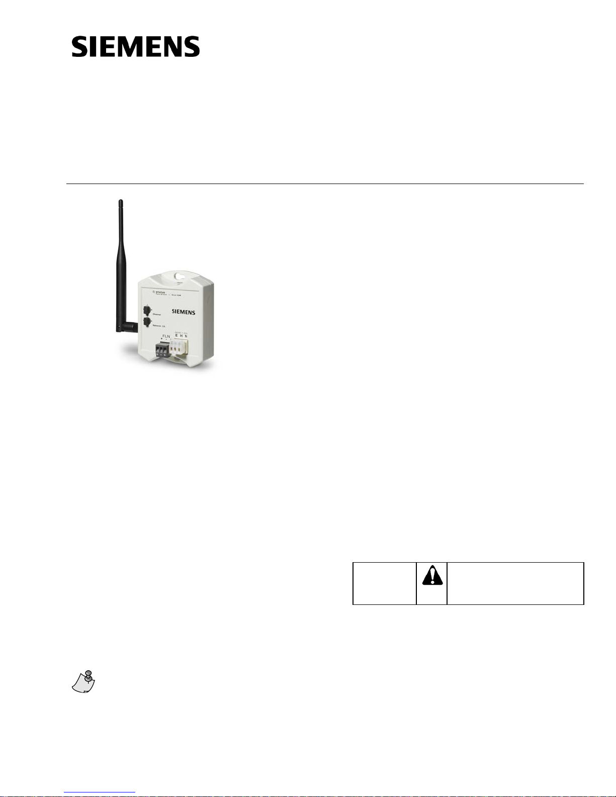
Figure 1. Wireless Field Level Network
Transceiver.
Product Description
The Wireless Field Level Network Transceiver
(FLNX) is mounted at or near the FLN device and is
powered by 24 Vac. The antenna can be mounted
directly to the radio or mounted remotely for
installations where the location of the FLNX causes
the antenna to be shielded—for example, when the
FLNX is mounted inside a TEC enclosure.
Product Numbers
563-054 Wireless Field Level Network
Transceiver (FLNX) with WRTS
Support (Version 2.x)
563-007 Direct Mount Antenna
563-008 Remote Mount Antenna
563-055 Wireless Field Panel
Transceiver (FPX)
563-056 Wireless Transceiver Tool (TLX)
QAA2290.EWSC Wireless TEC Room
Temperature Sensor (WRTS) –
Sensing only
QAA2290.DWSC Wireless TEC Room
Temperature Sensor (WRTS) –
Sensing with Temperature
Display
QAA2290.FWSC Wireless TEC Room
Temperature Sensor (WRTS) –
Sensing with Override, Setpoint,
and Temperature Display
Warning/Caution Notations
CAUTION:
Equipment damage, or loss of
data may occur if you do not
follow the procedures as
specified.
Expected Installation Time
10 minutes
Transceivers do not come with antennas.
Antennas must be ordered separately.
Item Number 563-201, Rev. CA Page 1 of 5
Required Tools and Materials
• Electro-static discharge wrist strap
• Small flat-blade screwdriver
• Cordless drill/driver set
Document No. 563-201
Installation Instructions
March 12, 2008
Prerequisites
• FPX for the WFLN is installed and powered.
The FPX generates the PAN ID, which is
needed for WFLN communications.
• All wiring must conform to NEC and local
codes and regulations.
• 24 Vac Class II power source is available.
• Metal Oxide Varistors (MOVs) must be used
for TECs that switch high voltage devices.
For details, see the FSN for Terminal
Equipment Controllers (TECs) Failing when
Switching High Voltage Powered Devices.
• Any application specific hardware or device
is installed.
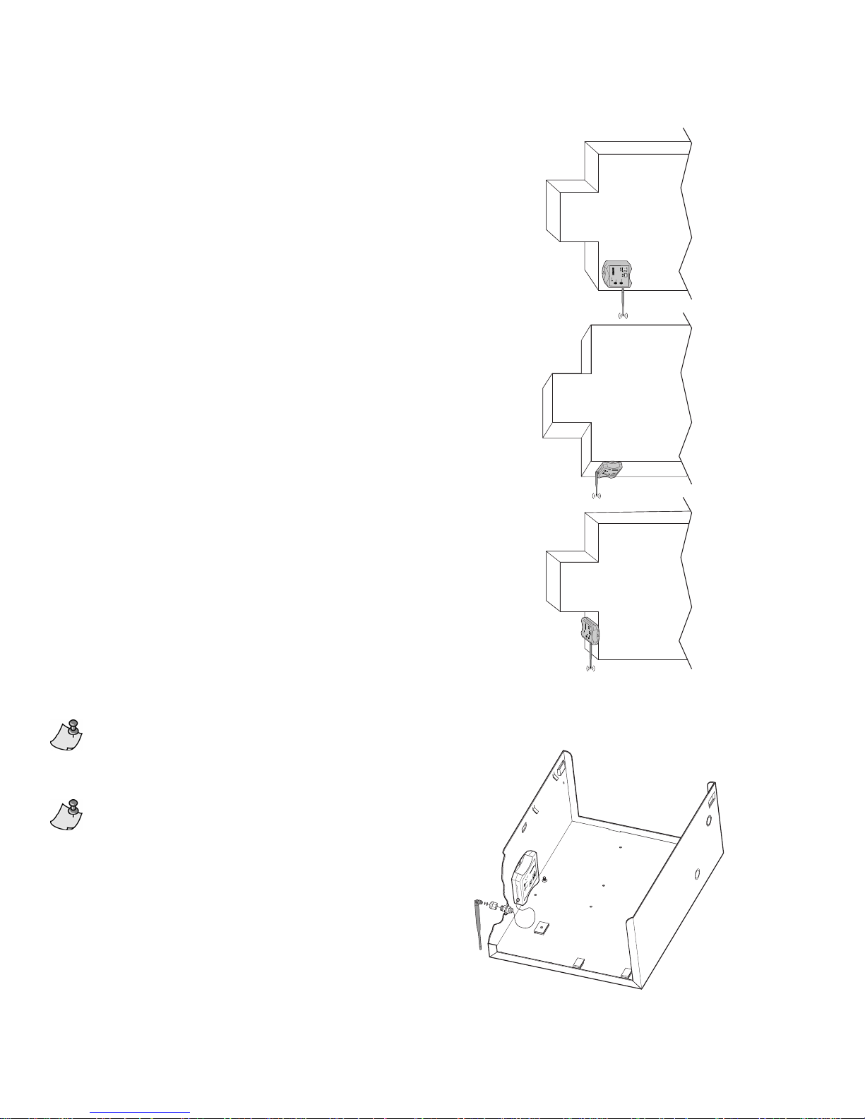
Antenna Mounting
VAV BOX
VAV BOX
Direct Mount Antenna
The preferred mounting configuration is to mount the
FLNX outside the TEC enclosure in a location where
it will establish the maximum number of
communication links with other FLNXs and its
associated FPX. For example, in a VAV application
this is typically on the bottom of the VAV box in the
ceiling plenum, with the entire antenna extending
downwards below the VAV box (Figure 2).
Remote Mount Antenna
The FLNX is mounted inside the TEC, or any metal
enclosure, and the antenna is brought through a
1/2 in. (1.3 cm) knockout (Figure 3).
The antenna extension cable is 12 in.
(30 cm) long.
The cable for the remote mount antenna
will cause a slight reduction in the FLNX’s
power and range, compared to using a
direct mount antenna.
VAV BOX
WLAN0069R1
Figure 2. FLNX Mounted Outside Enclosure.
Page 2 of 5 Siemens Building Technologies, Inc.
WLAN0071R1
Figure 3. FLNX Mounted Inside Enclosure.
 Loading...