

Siemens WF 725, WF 726 Planning Instructions

Equipment for Machine Tools
WF 725/WF 726
Positioning Modules
Planning Instructions
NC- Auxiliary axis and tool magazine
for SINUMERIK 3GA4
Edition August 1990

This publication was produced on the Siemens 5800 Office System.
Subject to change without prior notice.
The reproduction, transmission or use of this document or its
contents is not permitted without express written authority.
Offenders will be liable for damages. All rights, including rights
created by patent grant or registration of a utility model or
design, are reserved.
©
Siemens AG 1990 All Rights Reserved

Introduction
1
Description of the Functions
Technical Data
Use of the ”Programming
and Display Functions”
Checklist for Start-up/Search for Errors
Appendix
2
3
4
5
6

Index
Page
1 Introduction
2 Description of the Functions
. . . . . . . . . . . . . . . . . . . . . . . . . . . . . . . . . . . . . . . . . . . . . . . . . . . . . . . . . . . . . . . . . . . .
. . . . . . . . . . . . . . . . . . . . . . . . . . . . . . . . . . . . . . . . . . . . . . . . . .
1-1
2-1
2.1 Auxiliary axis . . . . . . . . . . . . . . . . . . . . . . . . . . . . . . . . . . . . . . . . . . . . . . . . . . . . .2-1
2.1.1 Description of the FB 203 . . . . . . . . . . . . . . . . . . . . . . . . . . . . . . . . . . . . . . . . . . 2-1
2.1.2 Notes for use of the FB 203
2.1.3 Parameterisation of the FB 203
2.2 Tool magazine drive
2.2.1 Description of the FB 204
2.2.2 Notes for use of the FB 204
2.2.3 Parameterisation of the FB 204
2.3 Input/Output of Machine Data and Operating Data
2.3.1 Description of the FB 205
2.3.2 Notes for use of the FB 205
2.3.3 Parameterisation of the FB 205
2.3.4 Allocation of the data block for tool magazine drive
3 Technical Data
3.1 Overview of blocks
. . . . . . . . . . . . . . . . . . . . . . . . . . . . . . . . . . . . . . . . . .
. . . . . . . . . . . . . . . . . . . . . . . . . . . . . . . . . . . . . . . . . . . . . . . . . . . . . . . . . . . .
3.1.1 Notes for the PLC software ”Programming and display functions”
. . . . . . . . . . . . . . . . . . . . . . . . . . . . . . . . . . . . . . . . . . . . . . . . . . . .
. . . . . . . . . . . . . . . . . . . . . . . . . . . . . . . . . . . . . . . . . . . . . . .
. . . . . . . . . . . . . . . . . . . . . . . . . . . . . . . . . . . . . . . . . . . . . . . . . . . . . . . . . . .
. . . . . . . . . . . . . . . . . . . . . . . . . . . . . . . . . . . . . . . . . . . . . . . . . . . . .
. . . . . . . . . . . . . . . . . . . . . . . . . . . . . . . . . . . . . . . . . . . . . . . . . . . .
. . . . . . . . . . . . . . . . . . . . . . . . . . . . . . . . . . . . . . . . . . . . . . .
. . . . . . . . . . . . . . . . . . . . . . .
. . . . . . . . . . . . . . . . . . . . . . . . . . . . . . . . . . . . . . . . . . . . . . . . . . . . .
. . . . . . . . . . . . . . . . . . . . . . . . . . . . . . . . . . . . . . . . . . . . . . . . . . . .
. . . . . . . . . . . . . . . . . . . . . . . . . . . . . . . . . . . . . . . . . . . . . . .
. . . . . . . . . . . . . . . . . . . . . .
. . . . . . .
2-5
2-5
2-7
2-7
2-10
2-10
2-12
2-12
2-14
2-15
2-16
3-1
3-1
3-2
3.1.2 Notes for the PLC software ”Basic functions” . . . . . . . . . . . . . . . . . . . . . . . . 3-2
3.1.3 Notes for the ”Basic program” and ”Package 1” of SINUMERIK 3
3.1.4 Overview of the used data blocks
3.2 Memory storage demand
. . . . . . . . . . . . . . . . . . . . . . . . . . . . . . . . . . . . . . . . . . . . . . . . . . . . .
3.2.1 Example for memory storage calculation
. . . . . . . . . . . . . . . . . . . . . . . . . . . . . . . . . . . . . . . . . . . .
. . . . . . . . . . . . . . . . . . . . . . . . . . . . . . . . . . . .
. . . . . . . . .
3-3
3-3
3-4
3-5
3.3 Start-up
3.3.1 Start-up function of the WF 725 or WF 726
. . . . . . . . . . . . . . . . . . . . . . . . . . . . . . . . . . . . . . . . . . . . . . . . . . . . . . . . . . . . . . . . . . . . . . . . .
. . . . . . . . . . . . . . . . . . . . . . . . . . . . . . . . . .
3-6
3-6
3.3.2 Start-up functions of the tool magazine drive . . . . . . . . . . . . . . . . . . . . . . . . 3-6
3.4 Selection of Mode and Operating Submode
3.5 General notes for use
3.6 Flags, times, counters
. . . . . . . . . . . . . . . . . . . . . . . . . . . . . . . . . . . . . . . . . . . . . . . . . . . . . . . . . .
. . . . . . . . . . . . . . . . . . . . . . . . . . . . . . . . . . . . . . . . . . . . . . . . . . . . . . . . . .
. . . . . . . . . . . . . . . . . . . . . . . . . . . . . . . .
3-6
3-7
3-8

4 Use of Programming and display func tions”
. . . . . . . . . . . . . . . . . . . . . . . . . . . . . .
4-1
4.1 Programming example
4.2 Structure of the block calls
5 Checklist for Start-up and search for errors
5.1 Supply of parameters
5.2 Data block (DB) for tool magazine axis
5.3 Machine data (MD) of the WF 725 or WF 726
5.4 Supply of Operating Submode (BA) and Mode
6 Appendix
. . . . . . . . . . . . . . . . . . . . . . . . . . . . . . . . . . . . . . . . . . . . . . . . . . . . . . . . . . . . . . . . . . . . . .
. . . . . . . . . . . . . . . . . . . . . . . . . . . . . . . . . . . . . . . . . . . . . . . . . . . . . . .
. . . . . . . . . . . . . . . . . . . . . . . . . . . . . . . . . . . . . . . . . . . . . . . . . . .
. . . . . . . . . . . . . . . . . . . . . . . . . . . . . . . . .
. . . . . . . . . . . . . . . . . . . . . . . . . . . . . . . . . . . . . . . . . . . . . . . . . . . . . . . . .
. . . . . . . . . . . . . . . . . . . . . . . . . . . . . . . . . . . . . .
. . . . . . . . . . . . . . . . . . . . . . . . . . . . . . .
. . . . . . . . . . . . . . . . . . . . . . . . . . . . .
4-1
4-4
5-1
5-1
5-1
5-1
5-1
6-1
6.1 Explanation of the function block (FB) descriptions . . . . . . . . . . . . . . . . . . . 6-1
6.2 Error messages of the WF 725 or WF 726 . . . . . . . . . . . . . . . . . . . . . . . . . . . . . 6-3
6.3 Data codings in the data block (DB) - Axis
6.4 Overview of Machine Data
6.5 Overview of Interface
6.6 List of the used abbreviations
. . . . . . . . . . . . . . . . . . . . . . . . . . . . . . . . . . . . . . . . . . . . . . . . . . .
. . . . . . . . . . . . . . . . . . . . . . . . . . . . . . . . . . . . . . . . . . . . . . . . . . . . . . . . .
. . . . . . . . . . . . . . . . . . . . . . . . . . . . . . . . . . . . . . . . . . . . . . . .
. . . . . . . . . . . . . . . . . . . . . . . . . . . . . . . . . . .
6-6
6-10
6-13
6-21
6.7 Needed Software . . . . . . . . . . . . . . . . . . . . . . . . . . . . . . . . . . . . . . . . . . . . . . . . . .6-22
6.8 Documentations . . . . . . . . . . . . . . . . . . . . . . . . . . . . . . . . . . . . . . . . . . . . . . . . . .6-23

08.90 Introduction
1 Introduction
This planning instruction describes the PLC software ”Programming and Display functions”
for WF 725 and/or WF 726 in SINUMERIK 3, GA4.
For many manufacturers of tool machines, it is desirable to be able to position auxiliary axes
in addiition to the four axes which can be traversed over the NC control of the medium
power class SINUMERIK 3, GA4.
With this, a tool magazine, a tool supplier or a loading portal could be realised with the tool
machine.
With the help of the positioning modules WF 725 and/or WF 726, up to 21 additional
auxiliary axes can be positioned without having to evade to an NC control of the higher class.
The PLC software described here fulfills the following functions:
– Setting of a single traversing block to the WF 725 or WF 726
Traversing path, traversing feed rate and path conditions are set over R-parameters
freely selectable in an NC part program. When the NC part program is executed, the
data is transmitted to the WF 725 or WF 726, and the auxiliary axes are immediately
traversed.
– Positioning of a tool magazine
Up to 120 magazine place positions can be selected over a parameter. The rotational
direction - ”right”, ”left” or ”shortest distance” can also be selected.
– Input/Output of Machine data and Operating Data
With display masks, the data mentioned above can be entered and changed. This
simplifies the start-up of the WF 725 or ”F 746.
– Display on the NC operator panel
The following data is shown for the selected axis
• Actual value
• Residual traversing path
• Feed rate
• Error
Or for positioning of tool magazine axes:
• Magazine location command
• Actual magazine location
• Error
©
Siemens AG 1990 All Rights Reserved 6ZB5 440-0JB02
WF 725/WF726 (PJ – NC Auxiliary axis and tool magazine for SINUMERIK 3GA4)
1 - 1

Introduction 08.90
Notes for use:
The PLC software ”Programming and display functions” can be used in SINUMERIK 3, GA4B
or SINUMERIK 3, GA4C with single or double PLC.
This applies for the following controls:
SINUMERIK 3T, 3TE
SINUMERIK 3TT, 3TTE
SINUMERIK 3M, 3ME
SINUMERIK 3G, 3GE
SINUMERIK 3FA
Up to seven WF 725 or WF 726 positioning modules can be used in a control.
Prerequisite for the use of the PLC software descibed here is the use of the PLC software
”Basic functions” (see chapter 6.7).
1 - 2 ©
WF 725/WF726 (PJ – NC Auxiliary axis and tool magazine for SINUMERIK 3GA4)
Siemens AG 1990 All Rights Reserved 6ZB5 440-0JB02

08.90 Description of the functions
2 Description of the functions
2.1 Auxiliary Axis
2.1.1 Description of the FB 203
With the FB-Auxiliary axis it is possible to enter a single traversing block in R-parameters into
the NC and to transmit the block to the set axis with the help of M-functions. With a further
M-function, the axis can be started. Parameterisation of the ”basic functions” must,
however, be executed according to the start-up and planning instruction of the
WF725/WF726.
The function block supplies the following functions:
• Transmission of path, feed rate and first G-function from the NC part program to the WF
module with the help of R-parameters.
• Display of check back signals on the monitor screen of the NC. The following values are
shown for each axis (BCD):
– Actual value
– Residual path
– Feed rate
– 1st G-Function
– Error messages of the WF725/WF726
– MODE of the module
– Operating Submode of the axis
– Wrong MODUS
– Wrong axis number in clear text
The residual traversing path will only be updated with start.
The axis number is selected over a parameter of the FB205.
©
Siemens AG 1990 All Rights Reserved 6ZB5 440-0JB02
WF 725/WF726 (PJ – NC Auxiliary axis and tool magazine for SINUMERIK 3GA4)
2 - 1

Description of the functions 08.90
Check back signals of the auxiliary axis on the screen of SINUMERIK 3
Example:
# # # # # # # # # # # # # #
R U E C K - M E L D U N G E N A C H S E 1 2
M O D U S 1 B A 3 F E H L E R 2 0 1
I S T - W E R T - 1 0 0 0 0 0 0
R E S T V E R F A H R W E G 0
G - F U N K T I O N 9 0
G E S C H W I N D I G K E I T 5 0 0 0
F A L S C H E R M O D U S
Significance:
Check back signals Axis 12
Mode 1 Operating Submode 3 Error 201
Actual Value - 1000000
Residual path - 0
G-Function - 90
Feed rate 5000
Wrong mode
2 - 2 ©
WF 725/WF726 (PJ – NC Auxiliary axis and tool magazine for SINUMERIK 3GA4)
Siemens AG 1990 All Rights Reserved 6ZB5 440-0JB02

08.90 Description of the functions
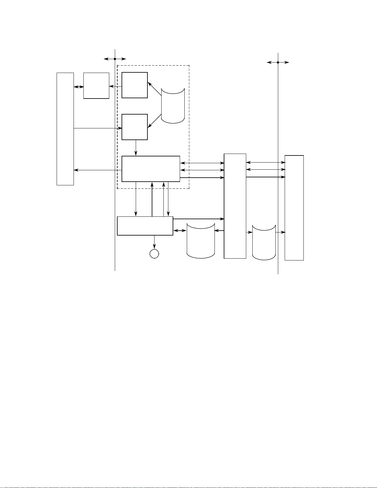
NC Part
program
PLC
R-Parameter
M-Function
M-Function
FB
program
User
W-UE
FB61
NC-Data output
blockwise (from
basic program of
SINUMERIK 3)
FB203
Auxiliary
axis
DB
Axis 1
START
FB
”Basic
functions”
for WF725/
WF726
PLC
WF725/WF726NC
Firmware
Figure 1 Structure of the software
MODE
SUBMODE
START
STOP
©
Siemens AG 1990 All Rights Reserved 6ZB5 440-0JB02
WF 725/WF726 (PJ – NC Auxiliary axis and tool magazine for SINUMERIK 3GA4)
2 - 3

Description of the functions 08.90
Example for NC program PP:
%100
N1 G00 X200 Z300 LF
:
:
N10 R50=100 R51=500 R52=90 M46 LF
(X) (F) (G)
:
:
N20 R50=80000100 R51=200 R52=91 M46 LF
(X) (F) (G)
:
:
N30 . . . .
It is not possible to program a negative R-parameter value for setting a negative traversing
path to the WF 725/WF 726. The value must be chosen so that the bit with the highest value
is set (Internal presentation, please compare with interface in the PLC area).
Representation
positive values: 0000 0000 to 7999 9999
negative values: 8000 0001 to 9999 9999
2 - 4 ©
WF 725/WF726 (PJ – NC Auxiliary axis and tool magazine for SINUMERIK 3GA4)
Siemens AG 1990 All Rights Reserved 6ZB5 440-0JB02

08.90 Description of the functions
2.1.2 Notes for use of the FB 203
• FBs to be loaded:
”Basic functions” (for use of WF725): FB207, 210, 211, 216
”Basic functions” (for use of WF726): FB207, 210, 211, 215, 216, 217
• The block must be called once for each axis.
• To transmit an R-parameter from the NC to the WF 725/ WF 726, the user must decode
the M-function set in the NC-program and set the corresponding bit in the parameter
W-UE. The values of the R-parameter ranges from 0 to 999 999.
• The parameter DU-8 is set at the end of a data transmission for one cycle. The user can
now start the corresponding axis.
• The user must realise the read-in disable and the read-in enable of the NC. The signal
DU-L (Data transmission operating) can be used for this.
• The display buffer for the feed rate is in the DB79 of DW117, 118.
2.1.3 Parameterisation of the FB 203:
HILFS-A
B
D,KH
D,KH
D,KH
D,KF
§E,BY
§E,BY
Signal description:
DBZU Assignment-DB (Parameterisation like FB211 from the ”Basic functions”)
RPW R-Parameter number for the path
RPG R-Parameter number for the first feed rate
RPGFR-Parameter-Nr. for the 1. G-Funktion
ACHS ACHS-NR.1... 21
Number of the axis to which the contents of the parameters must be transmitted.
NC NC-NR. 1... 4
Number of the NC from which the R-Parameter is to be read out.
DBZU
RPW
RPG
RPGF
ACHS
NC
W-UE
FEHL
DU-L
DU-B
§
A,BY
A,BI
I A,BI
W-UE Transmit values (Start of transmission)
©
Siemens AG 1990 All Rights Reserved 6ZB5 440-0JB02
WF 725/WF726 (PJ – NC Auxiliary axis and tool magazine for SINUMERIK 3GA4)
2 - 5

Description of the functions 08.90
Bit no. Significance
0
Transmit path to the WF
1
Transmit feed rate to the WF
2
Transmit 1st G-function to WF
3
reserved
7
reserved
The different bits are set with an M-function each. It is possible to transmit either 1
value, 2 values or 3 values at the same time to an NC. The values are transmitted
from the W-UE at the positive edge only when DU-L and DU-B are zero.
FEHL Parameterisation errors:
Bit no. Significance
wrong NC number
0
wrong axis number
1
wrong MODUS
2
reserved
3
reserved
7
DU-L Data transmission active is 1,
as long as the data is transmitted to the WF
DU-B Data transmission ended
is set at the end of transmission for a PLC cycle
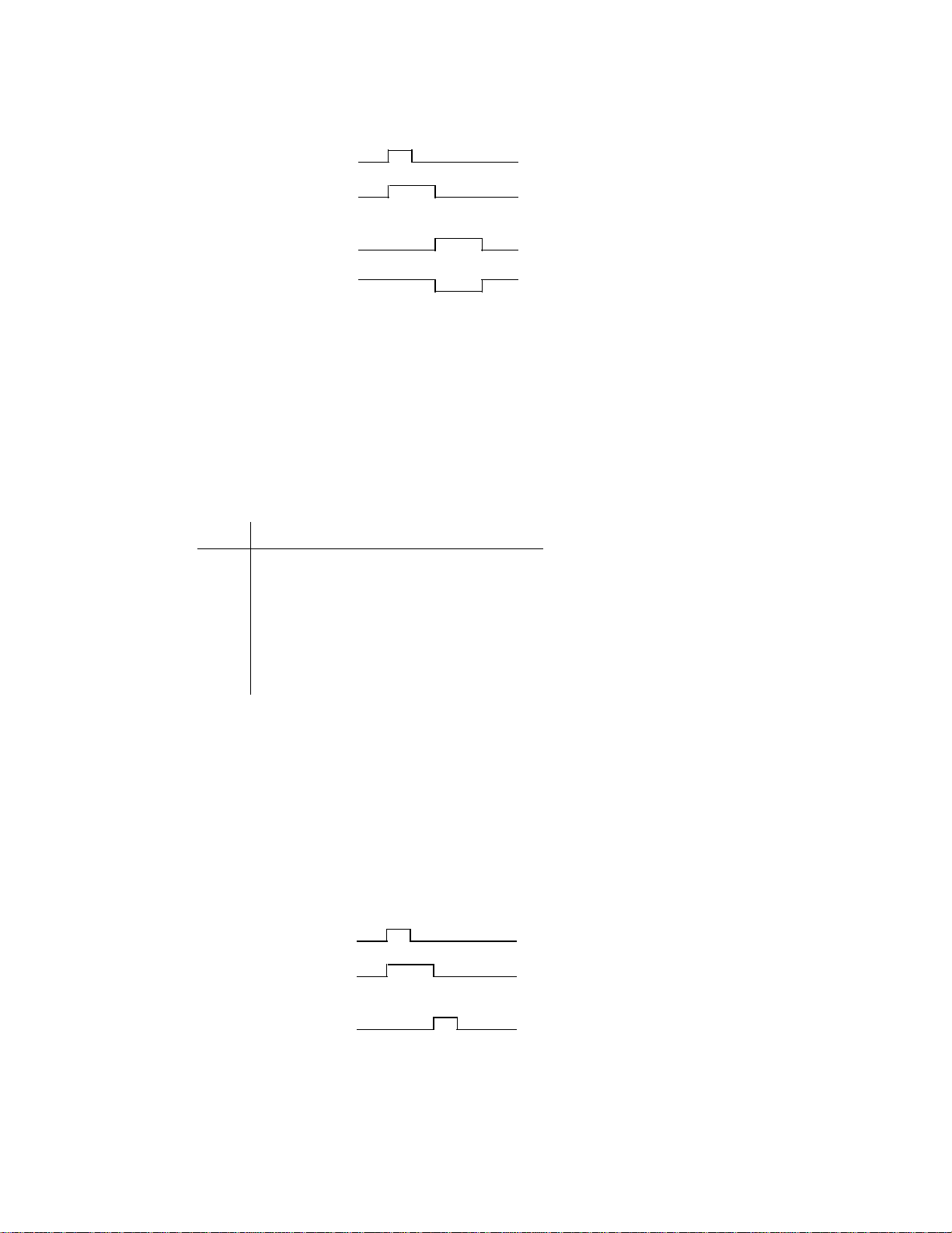
Demand
(set by the user)
Data transmission active
Transnmission ended
Note:
The signal DU-L can be used by the user for read-in disable.
1 Cycle
2 - 6 ©
WF 725/WF726 (PJ – NC Auxiliary axis and tool magazine for SINUMERIK 3GA4)
Siemens AG 1990 All Rights Reserved 6ZB5 440-0JB02

08.90 Description of the functions
2.2 Tool magazine drive
2.2.1 Description of the FB 204
The tool magazine drive positions up to 3 tool magazines or turrets. The maximum number
of magazine locations is 120 per axis. The command values for the single magazine locations
are deposited in a DB in form of a table.
The function block supplies the following functions:
• Transmission of feed rate from the DB tool magazine drive to the WF725/WF726 (Axis
1...3)
• Calculation of command position from revolver/magazine location number and
transmission to the WF725/WF726 (Axis 1...3)
• Output of the message ”Magazine position reached” after end of positioning.
• During conventional operation, the axis is traversed about 1 position each with the
signals jog+/jog-. When jog+/jog- are continually signalled, then the next position is
traversed to.
• Display of check back signals on the NC screen. For each axis, the following values are
shown (BCD):
– present magazine location number
– magazine location number to be traversed to
– Error messages of the WF725/WF726
– MODE of the module
– Operating submode of the axis
– Wrong MODUS
– Wrong axis number in clear text
If traversing is executed with jog+/jog-, the command magazoine location will not be
updated, instead, the value is displayed which is set as a parameter.
The axis number is selected with a parameter of the FB 205.
Der FB204 ermittelt aus der Magazinplatznummer anhand der Tabelle (DB WZ-M-A) den
Positionswert für die WF725/WF726 und startet anschließend die angewählte Achse.
Aus dem Istwert der von der Achse zurückgemeldet wird, wird durch Vergleich mit der
Tabelle (DB-WZ-M-A) der momentan angefahrene Magazinplatz ermittelt und über den
Parameter POSI im Dual-Code dem Anwender mitgeteilt. Ist der gewünschte Magazinplatz
erreicht, wird ein Ausgangsparameter gesetzt. Das Signal Datenübertragung läuft wird
ebenfalls als Parameter ausgegeben.
The FB204 calculates the position value for the WF 725/WF 726 from the magazine location
number of the table (DB WZ-M-A). The FB then starts the selected axis. The presently
traversed magazine location is calculated from the actual value signalled back from the axis
by comparing with the table (DB-WZ-M-A). This value is then transmitted to the user in the
binary code with the parameter POSI. If the desired magazine location is reached, then an
output parameter is set. The signal Data transmission active is also read out as a parameter.
©
Siemens AG 1990 All Rights Reserved 6ZB5 440-0JB02
WF 725/WF726 (PJ – NC Auxiliary axis and tool magazine for SINUMERIK 3GA4)
2 - 7

Description of the functions 08.90
Checkbacks of the tool magazine drive on the screen of SIMUMERIK 3
Example:
# # # # # # # # # # # # # #
R U E C K - M E L D U N G E N W Z - M - A 3
M O D U S 1 B A 3 F E H L E R 2 0 1
M A G A Z I N - P L A T Z S O L L 1 2
M A G A Z I N - P L A T Z I S T 6 4
F A L S C H E R M O D U S
Significance:
Check back signals WZ - M - A 3
Mode 1 Operating Submode 3 Error 201
Magazine location command 12
Magazine location actual 64
Wrong mode
2 - 8 ©
WF 725/WF726 (PJ – NC Auxiliary axis and tool magazine for SINUMERIK 3GA4)
Siemens AG 1990 All Rights Reserved 6ZB5 440-0JB02
08.90 Description of the functions
NC
PP
NC
Part
program
TO-Area
Tool
offset
values
T-Word
PLC
FB
Load data
to NC
FB
Selection
of tool
User
DB
Revolver
allocation
WF725/WF726PLC
FB
Read-in enable
FB 204
Figure 1.2 Structure of the software
Soll-Magazin-Platz
User
Act-Pos.Com-Pos.
Tool magazine drive
M
Drive
PE
MODE
SUBMODE
STOP
Turn right/left
shortest distance
DB WZ-M-A
Command
value for
magazine
location
START
FB
”Basic
functions”
for
WF725/
WF726
Firmware
DB
Axis 1
©
Siemens AG 1990 All Rights Reserved 6ZB5 440-0JB02
WF 725/WF726 (PJ – NC Auxiliary axis and tool magazine for SINUMERIK 3GA4)
2 - 9

Description of the functions 08.90
2.2.2 Notes for use of the FB 204
• FBs to be loaded:
”Basic functions” (for use of WF725): FB207, 210, 211, 216
”Basic functions” (for use of WF726): FB207, 210, 211, 215, 216, 217
Package 0: FB43
• DBs to be loaded: for each eaxis number
WZ-M-A 1: DB89
WZ-M-A 2: DB109
WZ-M-A 3: DB129
• The block must be called once for every tool magazine.
• If a magazine location is to be traversedm then the user must supply the signals RICH and
POSS. When STAR is set on the 1-signal, the corresponding path is transmitted to the
WF725/ WF 726, and the magazine is started at the end of the data exchange.
• The tool organisation must be realised by the user.
2.2.3 Parameterisation of the FB 204:
WZ-M-A
B
D,KF
§E,BY
§E,BY
E,BI /
E,BI /
E,BI
E,BI
Signal description:
DBZU Assignment DB to be supplied as FB211 in Standard I
ACHS Axis number 1-3
Number of the axis which is to be traversed
RICH Preselection of direction
0 = automatically shortest distance
1 = always right
2 = always left
DBZU
ACHS
RICH
POSS
STAR
G-UE
TIP+
TIP -
FEHL
POSI
MPE
GU-B
DU-L
A,BY
A,BY
A,BI
I A,BI
A,BI
POSS Command magazine location number (Hex-format)
STAR Start of axis
2 - 10 ©
WF 725/WF726 (PJ – NC Auxiliary axis and tool magazine for SINUMERIK 3GA4)
Siemens AG 1990 All Rights Reserved 6ZB5 440-0JB02
08.90 Description of the functions
1 Cycle
STAR
Data is transmitted
Magazine is
positioned
Magazine position
reached
As long as the data is transmitted or the magazine is positioned, a START by the user will not
be accepted.
G-UE Transmit feed rate
TIP+ Traverse to the right in the jog mode when the signal is 1.
TIP - Traverse to the right in the jog mode when the signal is 1.
FEHL Parameterisation error:
Bit no. Significance
0
free
1
wrong axis number
2
wrong mode
3
free
4
TIP+ and TIP- simultaneously
5
Error axis 1: magazine location number too high
6
Error axis 2: magazine location number too high
7
Error axis 3: magazine location number too high
POSI Actual magazine location number (Hexadecimal)
MPE Magazine location number reached
Nach Neustart oder Wiederanlauf wird das Signal Magazin-Position erreicht
zurückgesetzt. After start-up or restart, the signal Magazine Position Reached is set
back.
GU-B End of feed rate transmission
1 Cycle
Transmit feed rate
Data is transmitted
Transmission of feed
rate has ended
1 Cycle
DUL Data is transmitted
is ”1” Signal as long as data is exchanged to the WF
©
Siemens AG 1990 All Rights Reserved 6ZB5 440-0JB02
WF 725/WF726 (PJ – NC Auxiliary axis and tool magazine for SINUMERIK 3GA4)
2 - 11

Description of the functions 08.90
2.3 Input/Output of Machine Data and Operating Data
2.3.1 Description of the FB 205
The function block supplies the following functions:
• Input/output of MD (Axis 1...21).
• Input/output of reference point feed rates (Axis 1...21).
• Input/output of feed rate 1 and 2 for the operating submode Jog.
• The displays are selected with a menu.
• The menu is selected over the PLC-key of the SINUMERIK 3 operator panel.
• The user sets the desired axis number over the parameter ACHS. If the mask operating
data is selected, then the displayed values are updated automatically as soon as the axis
number is changed. The values are not changed when a number is not valid, an error
message is read out as a parameter.
Menu output on the screen of SINUMERIK 3
# # # # # # # # # # # # # #
0 S T A T U S - 0 R U E C K - M E L D U N G
- 1 W F M A - D A T E N
- 2 W F B E T R - D A T E N
2 - 12 ©
WF 725/WF726 (PJ – NC Auxiliary axis and tool magazine for SINUMERIK 3GA4)
Siemens AG 1990 All Rights Reserved 6ZB5 440-0JB02
 Loading...