

Page 1

Automation and Drives - SCE
Training Document
for Comprehensive Automation Solutions
Totally Integrated Automation (T I A)
MODULE F6
Operator Control
with
WinCC flexible 2005
and
TP177B
T I A Training Document Page 1 of 129 Module
F6
Issued: 02/2008 Operator Control with WinCC flexible 2005
Page 2

Automation and Drives - SCE
This document has been written by Siemens AG for training purposes for the project entitled "Siemens
Automation Cooperates with Education (SCE)".
Siemens AG accepts no responsibility for the correctness of the contents.
Transmission, use or reproduction of this document is only permitted within public training and educational
facilities. Exceptions require the prior written approval by Siemens AG (Michael Knust
michael.knust@siemens.com
).
Offenders will be liable for damages. All rights, including the right to translate the document, are reserved,
particularly if a patent is granted or utility model is registered.
We would like to thank the following: Michael Dziallas Engineering, the teachers at vocational schools, and all
others who helped to prepare this document.
T I A Training Document Page 2 of 129 Module
F6
Issued: 02/2008 Operator Control with WinCC flexible 2005
Page 3

Automation and Drives - SCE
1.
PREFACE.....................................................................................................................................................6
2. OPERATOR CONTROL WITH WINCC FLEXIBLE ....................................................................................8
2.1 SYSTEM DESCRIPTION .................................................................................................................................8
2.2 INSTALLATION/DEINSTALLATION ...................................................................................................................9
2.2.1 System Prerequisites.........................................................................................................................9
2.2.2 Installing WinCC flexible ..................................................................................................................10
2.2.3 Deinstalling WinCC flexible .............................................................................................................10
2.2.4 Totally Integrated Automation..........................................................................................................11
3. PROJECT DESCRIPTION .........................................................................................................................12
3.1 HARDWARE CONFIGURATION .....................................................................................................................12
3.2 PLANT DESCRIPTION .................................................................................................................................13
3.3 TASK DEFINITION.......................................................................................................................................14
3.4 CONFIGURATION........................................................................................................................................14
4 STEP7 PROJECT "COLOR MIXING PLANT“ .............................................................................................15
4.1 NEW PROJECT ..........................................................................................................................................15
4.2 HARDWARE CONFIGURATION .....................................................................................................................17
4.3 LIBRARY OF THE COLOR MIXING PLANT ......................................................................................................18
4.4 ASSIGNMENT LIST .....................................................................................................................................20
4.5 CONTROL PROGRAM .................................................................................................................................21
4.5.1 Function Block FB1..........................................................................................................................21
4.5.2 Variable Declaration ........................................................................................................................22
4.5.3 Inserting Panel Inputs FB5 as Multi Instance Block from the Program Library...............................23
4.5.4 Tank Block FB10 .............................................................................................................................26
4.5.5 Automatic Program Sequence FB15 ...............................................................................................29
4.5.6 Manual Operation FC20 ..................................................................................................................30
4.5.7 Mixer Motion FB25...........................................................................................................................31
4.5.8 Automatic and Manual Lamps .........................................................................................................31
4.5.9 Organization Block OB1 ..................................................................................................................32
4.6 LOADING TO THE CPU ...............................................................................................................................33
4.7 PROGRAM TEST ........................................................................................................................................33
5 SIMATIC HMI STATION ................................................................................................................................34
5.1 INSERTING AN HMI STATION ......................................................................................................................34
5.2 CONFIGURING THE HMI STATION ...............................................................................................................36
5.3 CHECKING THE CONNECTION WITH NETPRO ...............................................................................................37
5.4 OPENING THE HMI STATION.......................................................................................................................38
6 WINCC FLEXIBLE ENGINEERING SYSTEM ..............................................................................................39
6.1 PROGRAM INTERFACE................................................................................................................................39
6.1.1 Menus and Symbol Bars..................................................................................................................40
6.1.2 Work Space .....................................................................................................................................41
6.1.3 Project Window................................................................................................................................42
6.1.4 Property Window .............................................................................................................................43
T I A Training Document Page 3 of 129 Module
F6
Issued: 02/2008 Operator Control with WinCC flexible 2005
Page 4

Automation and Drives - SCE
6.1.5 Tool Window ....................................................................................................................................44
6.1.6 Output Window ................................................................................................................................45
6.1.7 Object Window.................................................................................................................................45
6.1.8 Resetting the Arrangement..............................................................................................................45
6.2 CONFIGURING DISPLAYS............................................................................................................................ 46
6.2.1 Display Template .............................................................................................................................47
6.2.2 Generating Displays ........................................................................................................................51
6.2.3 Inserting Graphic Displays...............................................................................................................52
6.2.4 Configuring Display Changes ..........................................................................................................55
6.3 SETTINGS AT THE TOUCH PANEL TP177B COLOR PN/DP ...........................................................................58
6.3.1 Setting the Date and the Time of Day .............................................................................................59
6.3.2 Setting the MPI Address ..................................................................................................................60
6.3.3 Setting the Profibus DP Address .....................................................................................................61
6.3.4 Assigning the Ethernet Address ......................................................................................................61
6.3.5 Setting the Transfer Properties........................................................................................................62
6.3.6 Transfer Mode .................................................................................................................................62
6.4 CHECKING FOR CONSISTENCY ...................................................................................................................63
6.5 TRANSFER SETTINGS AND DATA TRANSFER UNDER WINCC FLEXIBLE ..........................................................63
6.6 BUTTON END ...........................................................................................................................................65
6.7 CONFIGURING A CONNECTION....................................................................................................................67
7 DISPLAY AND OPERATOR OBJECTS .......................................................................................................68
7.1 LEVELS .....................................................................................................................................................68
7.2 BASIC OBJECTS ........................................................................................................................................69
7.3 EXPANDED OBJECTS .................................................................................................................................71
8 DISPLAY AND OPERATOR OBJECTS IN THE PROJECT "COLOR MIXING PLANT“............................72
8.1 CONFIGURING DISPLAY AND OPERATOR OBJECTS IN THE PICTURE“TANK1“..................................................72
8.1.1 Configuring the Bar Display.............................................................................................................72
8.1.2 Configuring the Linear Regulator.....................................................................................................76
8.1.3 Configuring a Button ........................................................................................................................79
8.1.4 Representing the Valve Function in Color.......................................................................................83
8.1.5 Testing the Picture “Tank1“ in Runtime ...........................................................................................86
8.2 CONFIGURING THE DISPLAY AND OPERATOR OBJECTS IN THE PICTURES “TANK2“ AND “TANK3“....................87
8.3 OBJECTS IN THE BASIC DISPLAY.................................................................................................................89
8.3.1 Tank Levels and Valve Representations.........................................................................................89
8.3.2 Configuring the Mixer Motor ............................................................................................................90
8.3.3 Configuring the Manual Mode for the Outflow Valve of the Container ........................................... 95
8.3.4 Switching Operating Modes.............................................................................................................97
8.3.5 Configuring the Fill Entries...............................................................................................................99
8.3.6 Configuring the “START“ Button....................................................................................................101
8.3.7 Configuring the Mixer Motion.........................................................................................................103
8.4 CONFIGURING OBJECTS IN THE PERMANENT WINDOW...............................................................................107
8.4.1 Configuring Text Fields..................................................................................................................107
8.4.2 Configuring the Output Fields........................................................................................................108
9 CONFIGURING MESSAGES ......................................................................................................................111
9.1 ANALOG MESSAGES ................................................................................................................................111
T I A Training Document Page 4 of 129 Module
F6
Issued: 02/2008 Operator Control with WinCC flexible 2005
Page 5
Automation and Drives - SCE
9.2 BIT MESSAGES........................................................................................................................................111
9.3 MESSAGE WINDOW .................................................................................................................................112
9.4 MESSAGE INDICATOR ..............................................................................................................................114
9.5 TESTING THE MESSAGE CONFIGURATION IN RUNTIME ...............................................................................115
10 CONFIGURING RECIPES .......................................................................................................................116
10.1 ADDING RECIPES .................................................................................................................................116
10.2 SPECIFYING DATA SETS.......................................................................................................................117
10.3 GENERATING THE PICTURES “RECIPE INPUT“ AND “RECIPE SELECTION“ .................................................117
10.3.1 Configuring the Picture “Recipe Input“ ..........................................................................................117
10.3.2 Configuring the picture "Recipe Selection“....................................................................................119
10.3.3 Configuring Buttons for Display Change .......................................................................................120
10.4 SELECTING RECIPES IN RUNTIME..........................................................................................................122
10.5 Entering New Recipes in Runtime.................................................................................................123
11 CONFIGURING USER MANAGEMENT..................................................................................................124
11.1 SETTING UP THE USER GROUP .............................................................................................................124
11.2 SETTING UP USERS .............................................................................................................................125
11.3 ASSIGNING AUTHORIZATIONS ...............................................................................................................126
11.3.1 Protecting the Start Button.............................................................................................................126
11.3.2 Protecting Data Selection ..............................................................................................................127
11.3.3 Protecting Recipe Input .................................................................................................................127
11.3.4 Protecting the Operating Mode Selection......................................................................................128
11.4 TESTING USER MANAGEMENT IN RUNTIME ............................................................................................129
The following symbols are provided as a guide through Module F6:
Information
Installation
Programming
Sample Exercise
Notes
T I A Training Document Page 5 of 129 Module
F6
Issued: 02/2008 Operator Control with WinCC flexible 2005
Page 6
Automation and Drives - SCE
y
days
odules
1. PREFACE
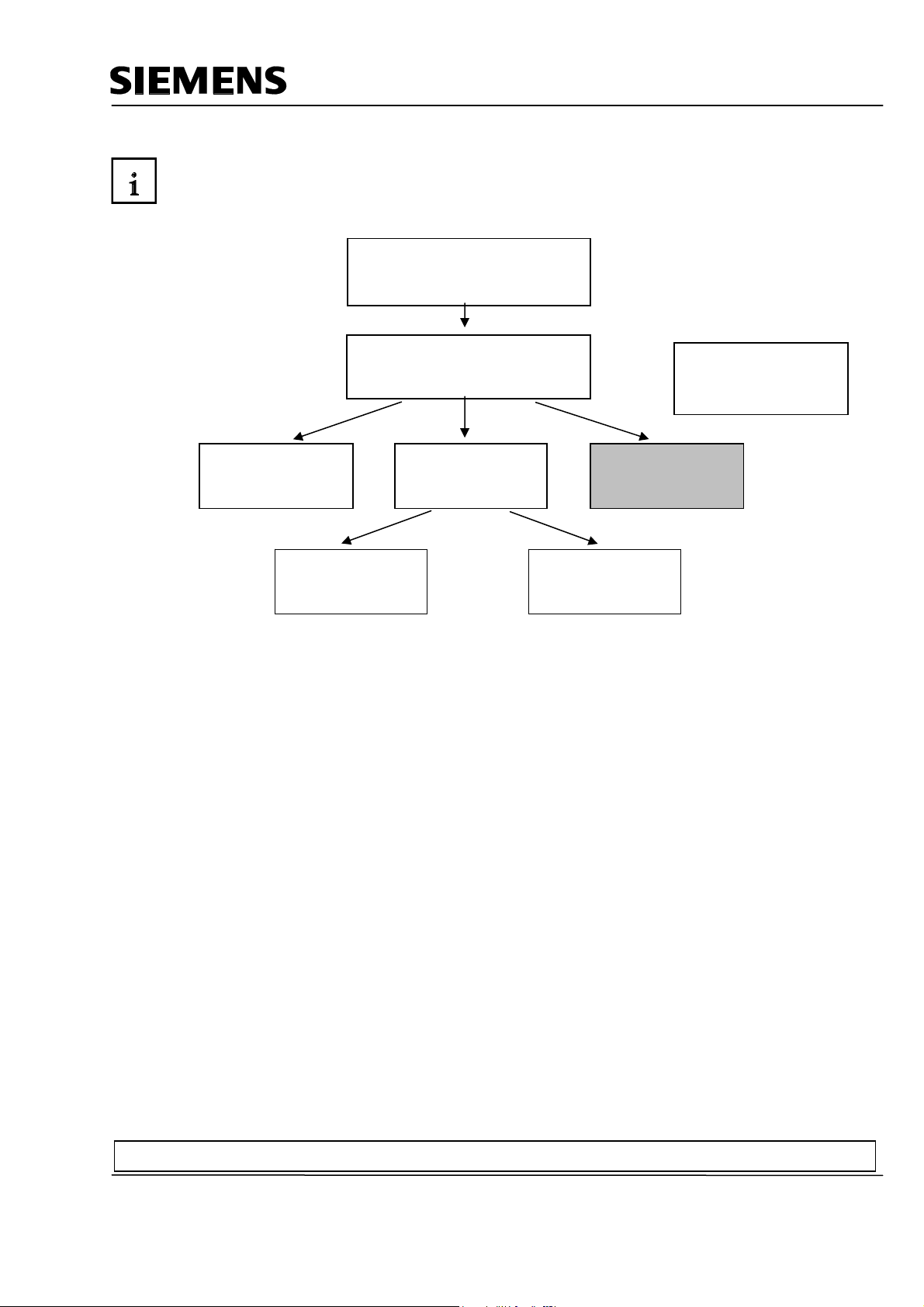
In terms of its contents, Module F6 is part of the teaching unit entitled 'Process Visualization’.
2 to 3 da
Additional Functions of
Programming
Languages
Frequency Converter
on SIMATIC S7
2 to 3 days Modules
Learning Objective:
In Module F6, the reader is introduced to the essential functions of the software WinCC flexible
2005.
Typical task definitions are processed using a sample system.
• Installing the software
Fundamentals of
STEP7 Programming
s Modules A
STEP7 Programming
2 to 3
Industrial Fieldbus
Systems
2 to 3 days Modules
M
B
Plant Simulation with
SIMIT SCE
1 to 2 days Modules G
Process
Visualization
2 to 3 days Modules
IT Communication
wirh SIMATIC S7
• Steps for generating a Step7 project
• Inserting an HMI station
• Interface of WinCC flexible
• Configuring display and operator objects
• Configuring messages
• Generating recipe management
• Setting up user management
Prerequisites:
• Knowledge in handling Windows
• Fundamentals of PLC programming with STEP 7 (for example, Module A3 - 'Startup’
PLC Programming with STEP 7)
Preface Installation Project Description Step7 Project HMI Station WinCC flexible Project Messages Recipes User Management
T I A Training Document Page 6 of 129 Module
F6
Issued: 02/2008 Operator Control with WinCC flexible 2005
Page 7
Automation and Drives - SCE
Hardware and software required
1 PC, operating system Windows 2000 SP4 or Windows XP Professional SP1 and SP2 with MS
Internet Explorer V6.0 SP1
Pentium IV with 1.6 GHz, 512MB RAM, approx. 1.5GB free hard disk storage
2 Software STEP7 V 5.4
3 Configuring software WinCC flexible 2005 Advanced
4 MPI interface for the PC (for example, PC Adapter USB)
5 Sample configuration for PLC SIMATIC S7-300:
- Power supply: PS 307 2A
- CPU: CPU 314
- Digital inputs: DI 16x DC 24V
- Digital outputs: DO 16x DC 24V/0.5A
6 Touch Panel TP177B
7 MPI or Profibus DP data cable for connecting the TP177B to the controller
1 PC
2 STEP7 V5.3
4 PC Adapter
3 Configuring Software WinCC
flexible 2005 Advanced
5 SIMATIC S7-300
7 MPI or Profibus DP
Data Cable
6 Touch Panel TP177B
Preface Installation Project Description Step7 Project HMI Station WinCC flexible Project Messages Recipes User Management
T I A Training Document Page 7 of 129 Module
F6
Issued: 02/2008 Operator Control with WinCC flexible 2005
Page 8

Automation and Drives - SCE
2. OPERATOR CONTROL WITH WINCC FLEXIBLE
2.1 System Description
Since processes are becoming more and more multi-layered and the demands on the functionality of
machines and plants are increasing, the operator needs a high-performance tool for controlling and
monitoring production plants. An HMI system (Human Machine Interface) represents the interface
between a human being (the operator) and the process (machine/plant). The controller actually
controls the process. That is, there are two interfaces: one between the operator and WinCC flexible
(at the operator panel), and another interface between WinCC flexible and the controller.
The WinCC flexible Engineering System is the software that is used to handle all required
configuring tasks. The WinCC flexible Edition determines which operator panels of the SIMATIC
HMI spectrum can be configured.
WinCC flexible Runtime is the software for process visualization. In runtime, the project is executed
in the process mode.
WinCC flexible performs the following tasks:
• Displaying the process
The process is mapped to the operator panel. If a status changes in the process, for example, the
display at the operator panel is updated.
• Operating the process
The operator can operate the process by means of the graphic operator interface. For example, the
operator can specify a setpoint for the controller, or start a motor.
• Reading out messages
If critical process states occur in the process, a message is triggered automatically; for example, if
the specified limit is exceeded.
• Archiving process values and messages
The HMI system can archive messages and process values. In this way, you can document the
process characteristics, and you can also access older production data later.
• Documenting process values and messages
The HMI system can read out messages and process values as protocol. Thus, you can have
production data read out after the end of a shift, for example.
• Managing process parameters and machine parameters
The HMI system can store parameters for processes and machines in recipes. With one operational
step, you can transfer these parameters from the operator panel to the controller, in order to change
production to another product variant.
Preface Installation Project Description Step7 Project HMI Station WinCC flexible Project Messages Recipes User Management
T I A Training Document Page 8 of 129 Module
F6
Issued: 02/2008 Operator Control with WinCC flexible 2005
Page 9
Automation and Drives - SCE
2.2 Installation/Deinstallation
2.2.1 System Prerequisites
WinCC flexible supports all common PC platforms that are IBM/AT compatible. Although values for a
minimum configuration are specified, you should use as a guide the recommended values for an
optimum configuration, for WinCC flexible to operate efficiently.
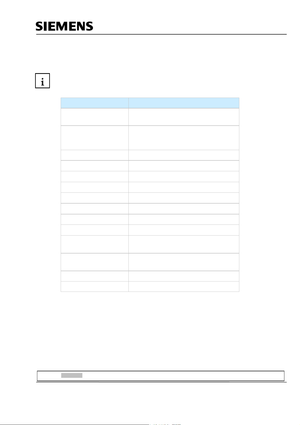
System Prerequisites for WinCC flexible ES
Operating System
Windows 2000 SP4, Windows XP Professional
SP1 and SP2
For multi-lingual configurations: Windows 2000
SP4 MUI, Windows XP Professional SP1 and
SP2 MUI
Processor
• Minimum
Pentium 4
• Recommended ≥ Pentium 4, 2.0 GHz
Resolution
• Minimum
1024 x 768
• Recommended ≥ 1280 x 1024
RAM
• Minimum
512 Mbyte
• Recommended ≥ 1 Gbyte, ≥ 512 Mbyte for WinCC flexible
micro
Hard disk drive (free
memory)
1)
≥ 1 Gbyte
Diskette drive 2)
CD-ROM
3.5“/1.44 Mbyte
for software installation
1) In addition to WinCC flexible, Windows also makes demands on the free hard disk drive capacity.
For example, free memory should be provided for the swap out file. The following formula has proven successful: Size of swap out file = 3
times the size of the RAM.
Additional information is provided in the Windows documentation
2) To transfer the License Key
Preface Installation Project Description Step7 Project HMI Station WinCC flexible Project Messages Recipes User Management
T I A Training Document Page 9 of 129 Module
F6
Issued: 02/2008 Operator Control with WinCC flexible 2005
Page 10
Automation and Drives - SCE
2.2.2 Installing WinCC flexible
After all system requirements that have been mentioned are met, install WinCC flexible from the CDROM. Select the scope for installing components and product languages.
• Standard installation: recommended
• Minimum installation: to save memory
• User defined installation: to specify yourself which components and product languages are
installed
In addition, the required licenses have to be transferred. You can install the licenses along with the
components and product languages, or you can install them subsequently. If you have obtained
WinCC flexible options, install each option separately. An option is installed by loading the
associated license key.
Detailed information regarding the installation are provided in the Installation Instructions on the CDROM 'WinCC flexible Software CD1’ in the folder "Documents\<Language>\Installation Guides“.
2.2.3 Deinstalling WinCC flexible
Close all applications that are open, particularly the WinCC flexible Engineering System and WinCC
flexible Runtime. Deactivate WinCC flexible Smart Start.
Additional notes on WinCC flexible Smart Start are provided in the chapter "WinCC flexible Smart
Start".
Open the system control by means of "Start ► Settings ► System Control".
In the system control, double click on the entry "Software". The dialog "Software" is opened.
In the dialog "Software", select the entry "SIMATIC WinCC flexible 2005". The button
"Change/remove" is displayed.
Click on the button "Change/Remove". The WinCC flexible InstallShield Wizard is opened.
Activate the option "Remove program" and click on the button "Continue".
Confirm the deinstallation with "OK". WinCC flexible is removed from the configuring computer.
In the dialog that follows, close the deinstallation with the button "Complete".
Preface Installation Project Description Step7 Project HMI Station WinCC flexible Project Messages Recipes User Management
T I A Training Document Page 10 of 129 Module
F6
Issued: 02/2008 Operator Control with WinCC flexible 2005
Page 11

Automation and Drives - SCE
2.2.4 Totally Integrated Automation
In addition to an HMI system such as WinCC flexible, a complete automation solution includes other
components, such as controller, process bus and periphery. WinCC flexible offers a particularly
extensive integration with components from the SIMATIC product family:
• Integrated configuring and programming
• Integrated data management
• Integrated communication
Integration in SIMATIC STEP 7
Process variables are the connecting link for communication between controller and the HMI system.
Without the advantages of Totally Integrated Automation, you have to define each variable twice:
once for the controller, and once for the HMI system.
Integrating SIMATIC STEP7 into the configuration interface lowers error frequency and configuring
effort. While you are configuring, you are directly accessing the STEP7 symbol table and the
communication settings:
- The STEP7 symbol table includes the data point definitions (for example, addresses or data
types) that were specified when you generated the control program.
- The communication settings contain the bus addresses and the control protocols
- Communication is set with NetPro, for example.
Preface Installation Project Description Step7 Project HMI Station WinCC flexible Project Messages Recipes User Management
T I A Training Document Page 11 of 129 Module
F6
Issued: 02/2008 Operator Control with WinCC flexible 2005
Page 12
Automation and Drives - SCE
3. PROJECT DESCRIPTION
3.1 Hardware Configuration
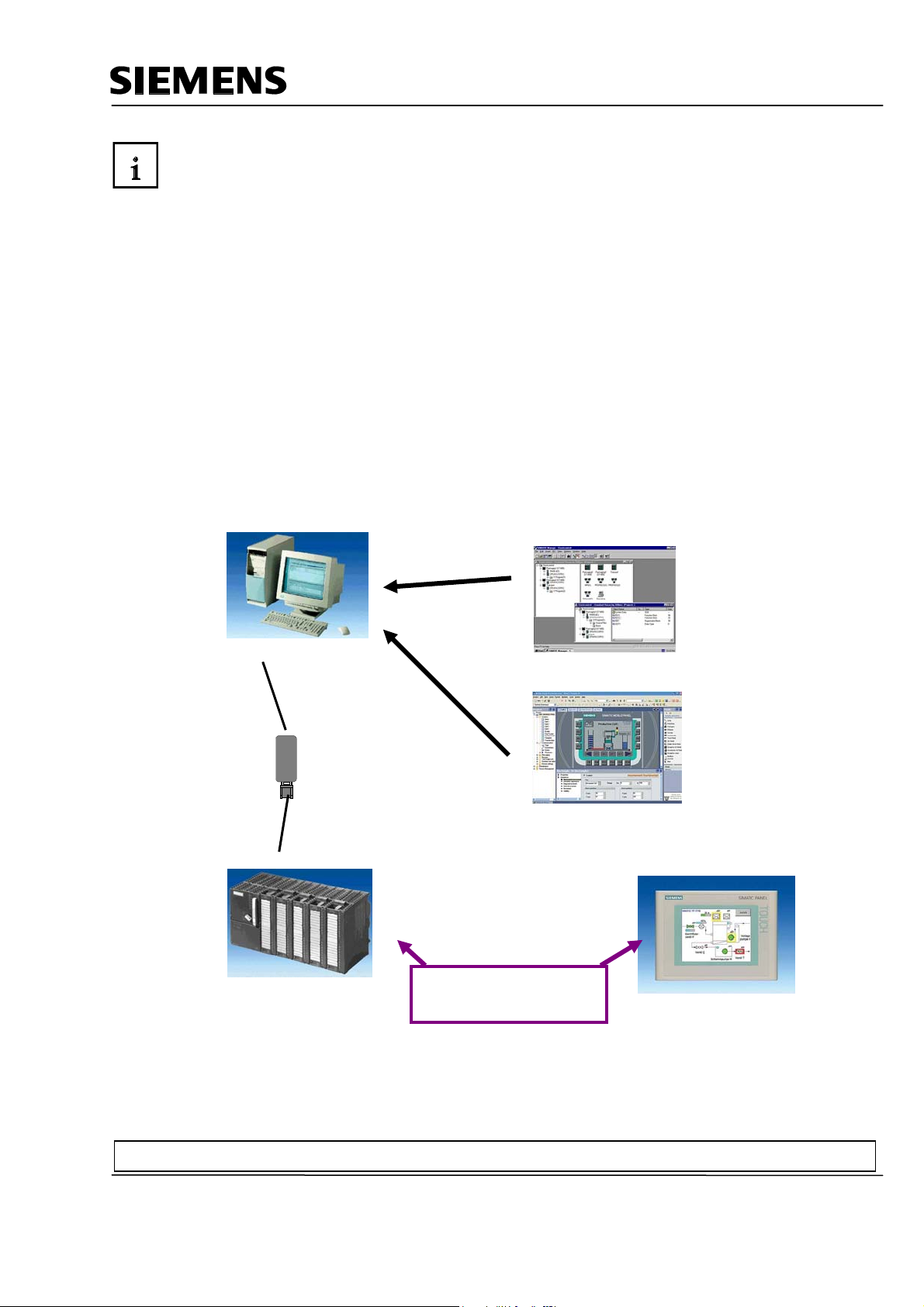
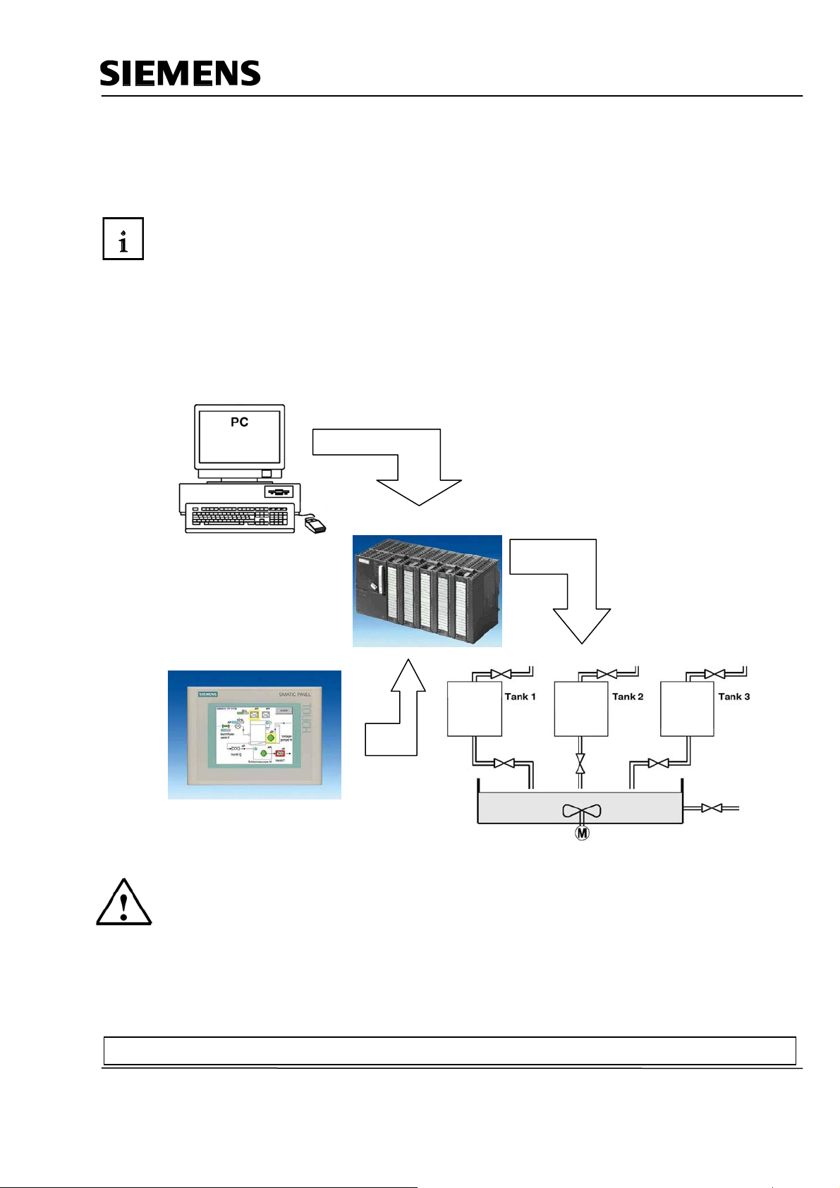
In our sample program for a color mixing plant, we are using a programming device with the WinCC
flexible 2005 Advanced Engineering System and WinCC flexible 2005 Runtime.
The color mixing plant is controlled by means of a SIMATIC S7-300. By using a touch panel
(TP177B), the operator can operate the process using the graphic operator interface. For example,
the operator can specify a setpoint for the controller, or start a motor.
The programming device, the SIMATIC S7-300 controller and the operator panel TP177B are
connected to each other by means of the MPI.
The color mixing plant is connected to the controller with digital inputs and outputs.
PC for Configuring
TP177B as operator panel
Note
With WinCC flexible 2005 Runtime, the touch panel TP177B can also be represented on the
programmer. However, when starting WinCC flexible Runtime, the MPI address of the panel
(MPI=1) is set automatically on the programmer. When using a real panel, the MPI address has to
first be reset on the programmer to MPI=0.
Preface Installation Project Description Step7 Project HMI Station WinCC flexible Project Messages Recipes User Management
T I A Training Document Page 12 of 129 Module
F6
Issued: 02/2008 Operator Control with WinCC flexible 2005
Page 13
Automation and Drives - SCE
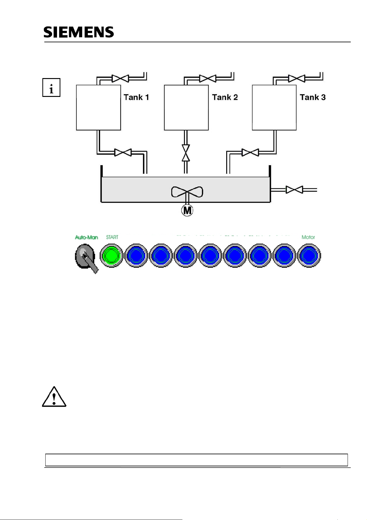
3.2 Plant Description
T1 Inflow
T1 Outflow
T2 Inflow T2 Outflow
T3 Inflow
Container
A color mixing plant is controlled with a SIMATIC S7-300 in the automatic or in the manual mode. In
the "Automatic“ mode, the three tanks are filled with a two step control. At the minimum level, the
inflow valve opens automatically, and after the maximum level is reached, it is closed again. After the
start button is operated, the specified program is executed: first, the outflow valves are opened and
the container is filled from tanks with the specified amounts. After the outflow valves are closed, the
mixer motor is started. After the mixing time has expired and after a short idle phase, the outflow
valve of the container is opened and the finished color mixture is drained. When the container is
empty, the lamp of the start button lights up, and a new color mixture can be started.
In the "Manual“ mode, the automatic outflow is canceled, and all valves as well as the mixer motor
can be operated manually. The lamps in the buttons for manual operation are lit.
Note
The specified amounts and the time base are determined by the program. If you want another color
mixture, the specified amounts and the time base have to be changed, and a new program has to be
loaded to the controller.
Preface Installation Project Description Step7 Project HMI Station WinCC flexible Project Messages Recipes User Management
T I A Training Document Page 13 of 129 Module
F6
Issued: 02/2008 Operator Control with WinCC flexible 2005
Page 14
Automation and Drives - SCE
3.3 Task Definition
At the color mixing plant, the program was changed with the programmer each time the mixing ratio
changed. Since such changes are not only time consuming, but also dangerous if wrong entries are
made, it was decided to expand the color mixing plant with a TouchPanel TP177B.
By using the panel, the following requirements are to be met:
- The color mixing plant can also be operated with the panel.
- The levels of the tanks and the container are to be displayed as a bar and also as a numerical
value.
- The motion of the mixing motor is to be shown graphically.
- The specified amounts are to be entered on the panel.
- The minimum and maximum levels of the three tanks are to be entered in separate tank
graphics.
- The operating modes can be switched using the panel; the respective operating mode is
displayed on the panel.
- The completed mixtures are to be stored on the panel as recipes; the operator only has to select
them.
- The levels are monitored. If danger arises, messages are to be read out.
- The color mixing plant can only be operated after a password was entered.
- Panel TP177B is to communicate with the SIMATIC S7-300 controller by means of the MPI.
3.4 Configuration
On the programmer, process visualization is generated for the color mixing plant, using the
configuring software WinCC flexible 2005 Advanced. The process values are represented by
graphics and graphic objects. Default values can be transferred to the controller with operating
elements. The operator panel and the machine or the process communicate by means of variables
via the controller. The value of a variable is written to a memory area (address) in the controller.
There, it is read by the operator panel.
Process visualization is stored and after generation, it is transferred by the programming device to
the operator panel TP177B.
After the panel is powered up, the process can be monitored and the plant can be operated.
Preface Installation Project Description Step7 Project HMI Station WinCC flexible Project Messages Recipes User Management
T I A Training Document Page 14 of 129 Module
F6
Issued: 02/2008 Operator Control with WinCC flexible 2005
Page 15
Automation and Drives - SCE
4 STEP7 PROJECT "COLOR MIXING PLANT“
4.1 New Project
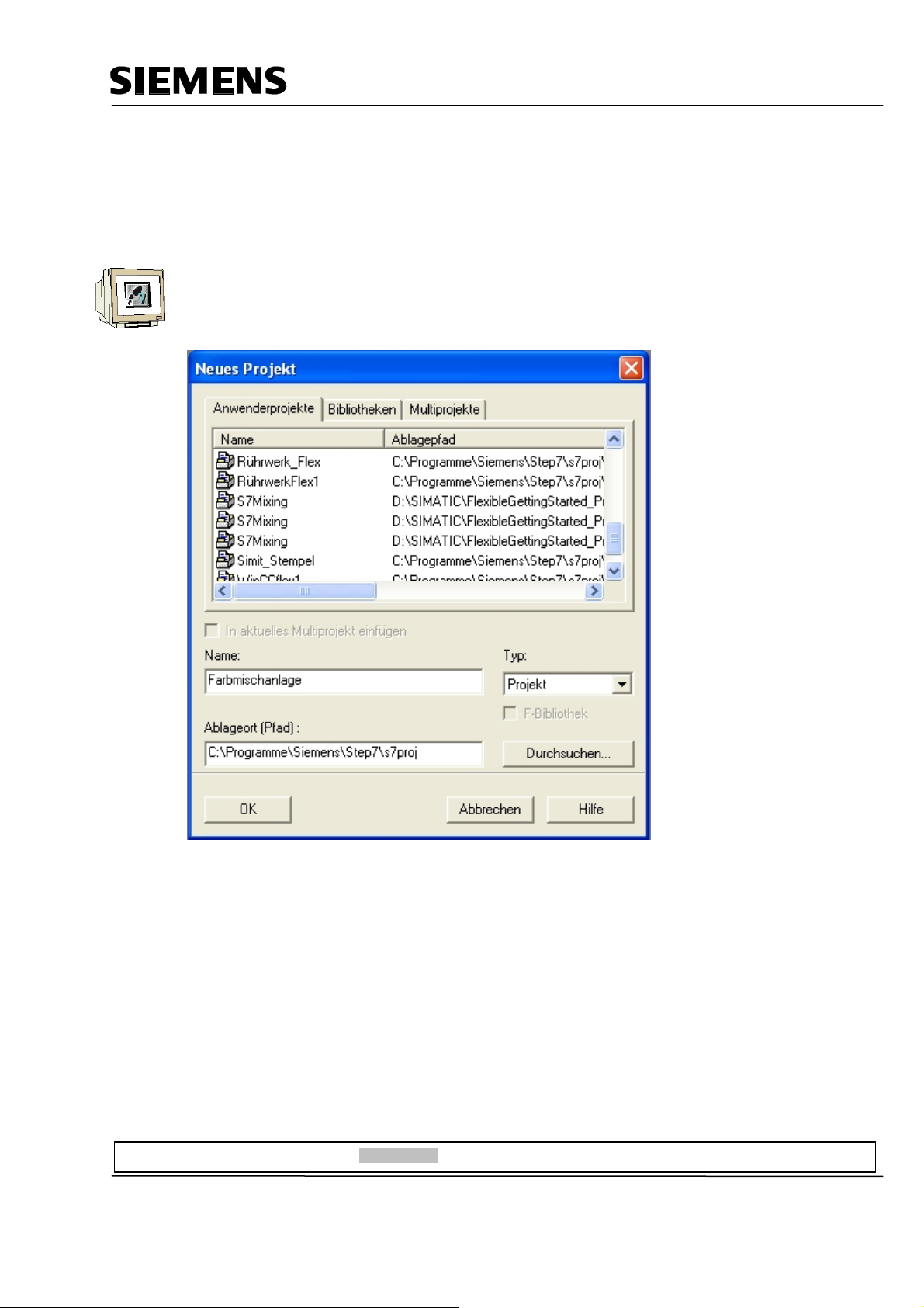
Start the SIMATIC Manager.
Create a new project with the Name “Color Mixing Plant“.
Preface Installation Project Description Step7 Projekt HMI Station WinCC flexible Project Messages Recipes User Management
T I A Training Document Page 15 of 129 Module
F6
Issued: 02/2008 Operator Control with WinCC flexible 2005
Page 16
Automation and Drives - SCE
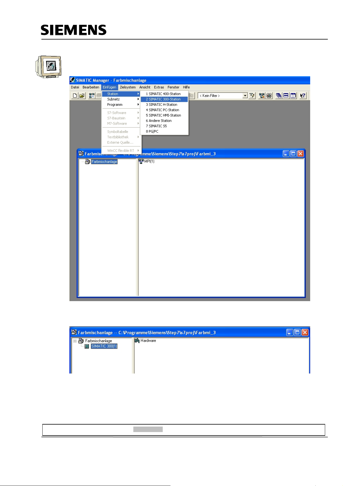
Insert the SIMATIC 300 Station.
By double clicking on Hardware, start the hardware configuration.
Preface Installation Project Description Step7 Projekt HMI Station WinCC flexible Project Messages Recipes User Management
T I A Training Document Page 16 of 129 Module
F6
Issued: 02/2008 Operator Control with WinCC flexible 2005
Page 17
Automation and Drives - SCE
4.2 Hardware Configuration
Enter the hardware configuration of the controller you are using. Take note of the settings in the
sample configuration.
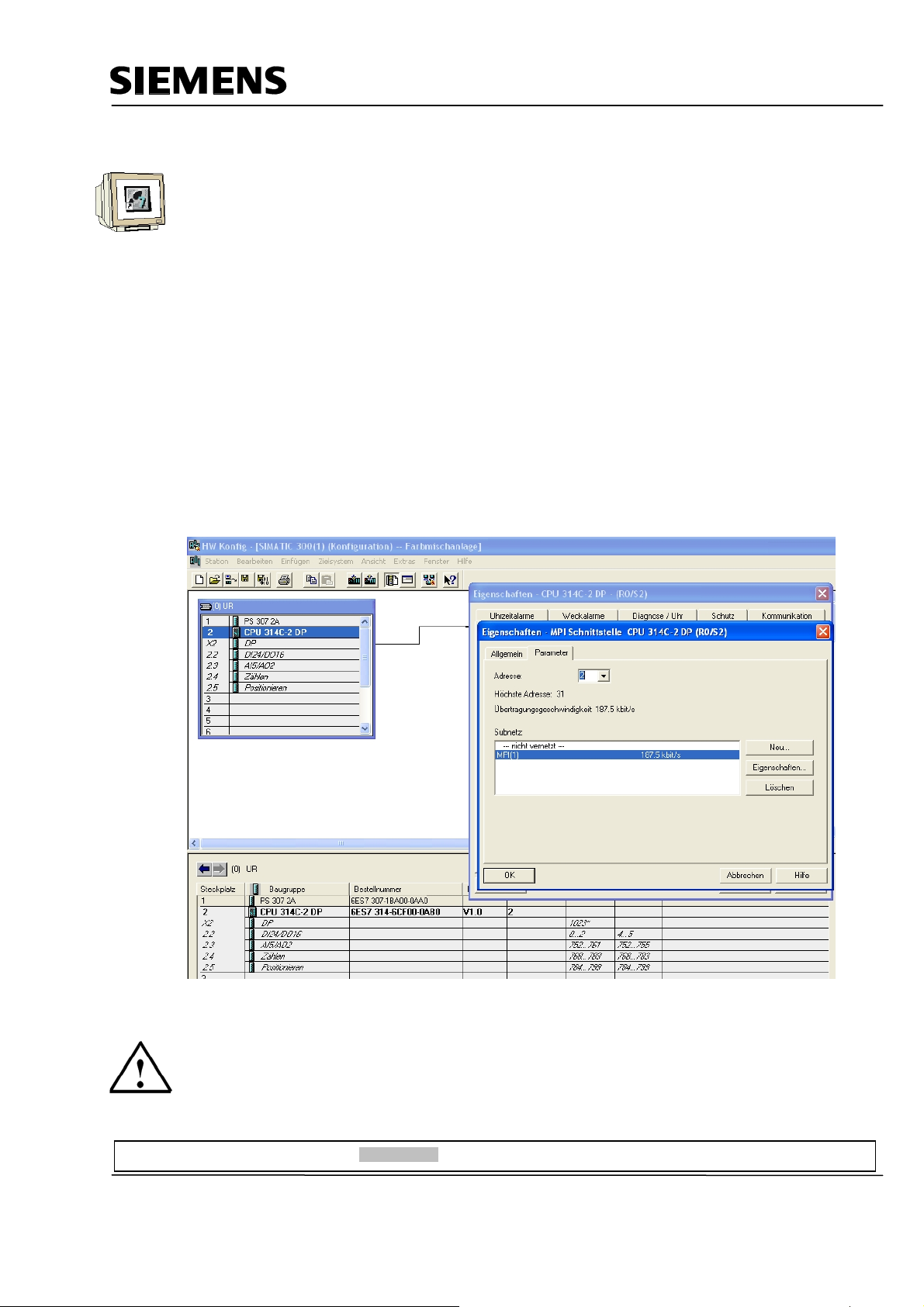
For our mixing plant, we are using the following hardware:
Slot 1: PS307 2A 6ES7 307-1BA00-0AA0
Slot 2: CPU 314C-2DP 6ES7 314-6CF00-0AB0
The CPU 314C-2DP is assigned the Profibus DP Addr.2 and is connected.
The CPU 314C-2DP is assigned the MPI Addr.2 and is connected.
The clock flag is set to MB100.
At the integrated inputs and outputs DI24/DO16, the inputs are set starting with Address 0, and the
outputs starting with Address 4.
Save and compile the hardware configuration.
Load the hardware to the PLC.
Close the hardware configuration.
Note
The SIMATIC S7 controller can also be simulated with the PLC simulator PLC SIM.
However, the simulator has to be started prior to loading the hardware to the CPU.
Preface Installation Project Description Step7 Projekt HMI Station WinCC flexible Project Messages Recipes User Management
T I A Training Document Page 17 of 129 Module
F6
Issued: 02/2008 Operator Control with WinCC flexible 2005
Page 18
Automation and Drives - SCE
4.3 Library of the Color Mixing Plant
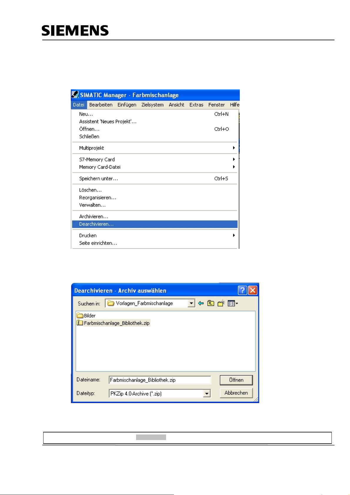
First, the library with the program blocks has to be imported to the SIMATIC Manager. To this end,
select the function Dearchive in the menu File.
From the template directory, select the file “Color mixing plant_Library“.
Click on the button “Open“.
Preface Installation Project Description Step7 Projekt HMI Station WinCC flexible Project Messages Recipes User Management
T I A Training Document Page 18 of 129 Module
F6
Issued: 02/2008 Operator Control with WinCC flexible 2005
Page 19
Automation and Drives - SCE
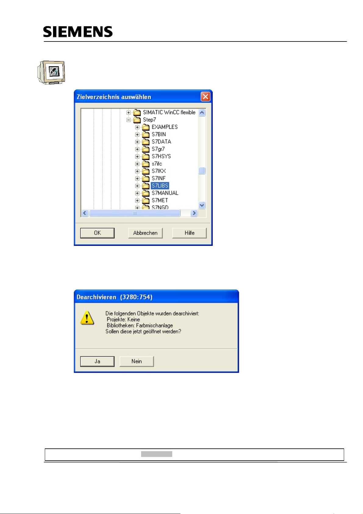
As destination directory, select the folder “S7LIBS“ in the Step7 directory.
Confirm with OK.
In the following window, click on the button “No“
<<the following objects were dearchived: Projects: None. Libraries: color mixing plant. Do you want to open
them now?>>
The project library “Color mixing plant“ was copied to the library directory. Here, all required program
blocks are stored.
Preface Installation Project Description Step7 Projekt HMI Station WinCC flexible Project Messages Recipes User Management
T I A Training Document Page 19 of 129 Module
F6
Issued: 02/2008 Operator Control with WinCC flexible 2005
Page 20
Automation and Drives - SCE
r
r
A
r
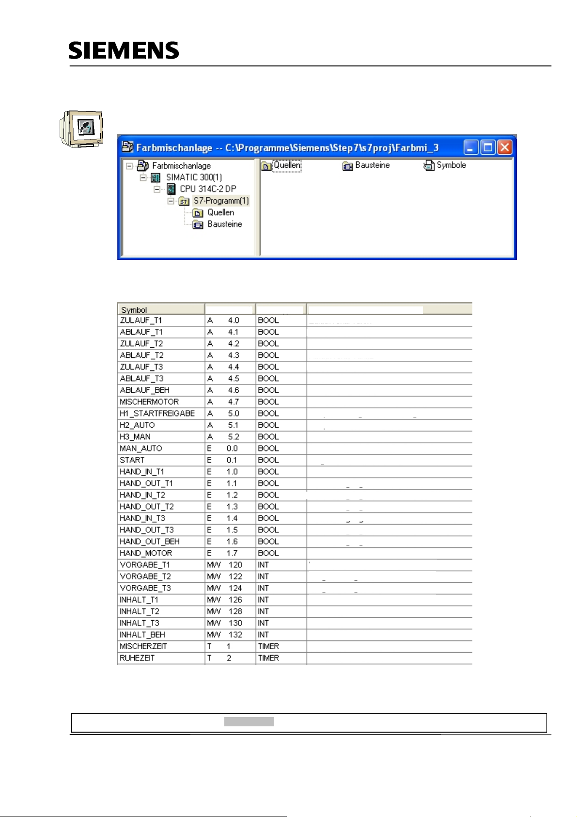
4.4 Assignment List
Open the project window in the symbol table.
Enter the symbol assignments in the symbol table.
ddress
CommentData Type
Inflow valve Tank 1
Outflow valve Tank 1
Inflow valve Tank 2
Outflow valve Tank 2
Inflow valve Tank 3
Outflow valve Tank 3
Outflow valve Containe
Motor for the mixe
Lamp for program start enable
Lamp for automatic mode
Lamp for manual mode
Manual-Automatic switch Auto = 1
Start program
Manual operation for inflow valve of Tank 1
Manual operation for outflow valve of Tank
Manual operation for inflow valve of Tank
Manual operation for outflow valve of Tank
Manual operation for inflow valve of Tank 3
Manual operation for outflow valve of Tank
Manual operation for outflow valve of container
Manual operation for mixer motor
Specified amount for Tank1
Specified amount for Tank2
Specified amount for Tank 3
Tank content Tank1
Tank content Tank2
Tank content Tank3
Tank content of containe
Mixer time in S5 format
Idle time in S5 format
Save and Close the symbol table.
Preface Installation Project Description Step7 Projekt HMI Station WinCC flexible Project Messages Recipes User Management
T I A Training Document Page 20 of 129 Module
F6
Issued: 02/2008 Operator Control with WinCC flexible 2005
Page 21
Automation and Drives - SCE
4.5 Control Program
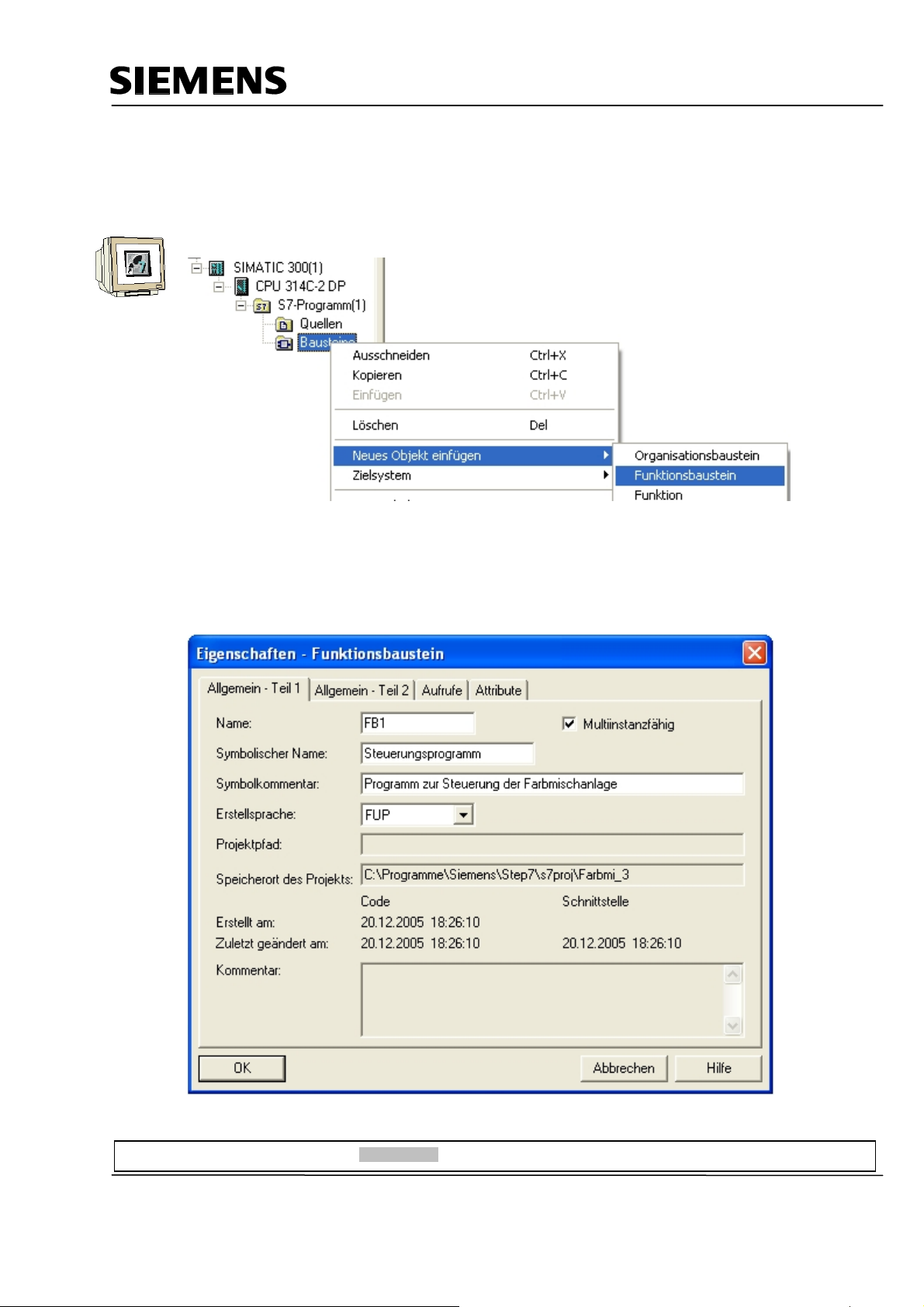
4.5.1 Function Block FB1
With the right mouse key, generate the FB1 in the folder Blocks.
Enter the symbolic name and the symbol comment.
Select the programming language “FBD“.
Place the check mark at Multi-instance capability.
Confirm with OK.
Preface Installation Project Description Step7 Projekt HMI Station WinCC flexible Project Messages Recipes User Management
T I A Training Document Page 21 of 129 Module
F6
Issued: 02/2008 Operator Control with WinCC flexible 2005
Page 22
Automation and Drives - SCE
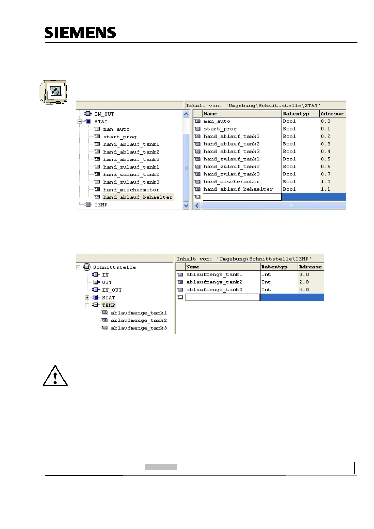
4.5.2 Variable Declaration
Open FB1 with a double click.
Enter the following STAT variables.
<<hand_ablauf = manual outflow; hand-zulauf = manual inflow; hand_ablauf_behaelter = manual outflow
container>>
Enter the following TEMP variables.
<<ablaufmenge = outflow amount>>
Note
The STAT variables are connected to the operator buttons on touch panel TP177B.
The TEMP variables are needed for passing on values in FB1.
Preface Installation Project Description Step7 Projekt HMI Station WinCC flexible Project Messages Recipes User Management
T I A Training Document Page 22 of 129 Module
F6
Issued: 02/2008 Operator Control with WinCC flexible 2005
Page 23
Automation and Drives - SCE
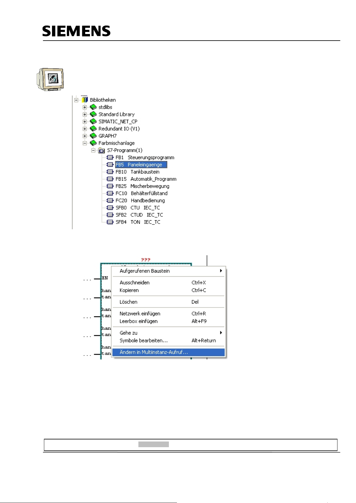
4.5.3 Inserting Panel Inputs FB5 as Multi Instance Block from the Program Library
Drag FB5 for the panel inputs from the library “Color mixing plant“ to Network 1.
This block is needed for connecting the input signals from the panel to the inputs of the controller.
Right click on the inserted block and select “Change in multi-instance call“.
Preface Installation Project Description Step7 Projekt HMI Station WinCC flexible Project Messages Recipes User Management
T I A Training Document Page 23 of 129 Module
F6
Issued: 02/2008 Operator Control with WinCC flexible 2005
Page 24
Automation and Drives - SCE
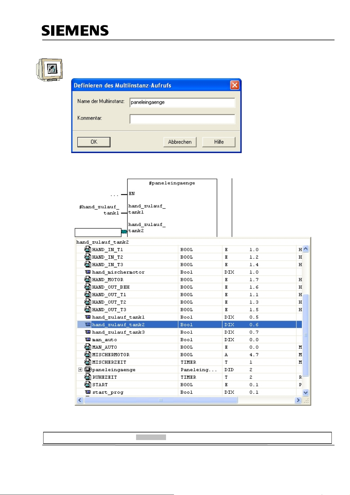
Enter the name “panel inputs“.
Confirm with OK.
Wire the upper 10 inputs of the block to the STAT variables.
Preface Installation Project Description Step7 Projekt HMI Station WinCC flexible Project Messages Recipes User Management
T I A Training Document Page 24 of 129 Module
F6
Issued: 02/2008 Operator Control with WinCC flexible 2005
Page 25
Automation and Drives - SCE
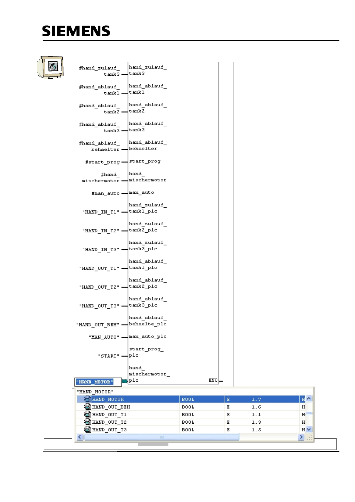
Wire the lower 10 inputs of the block with the symbolic names.
Preface Installation Project Description Step7 Projekt HMI Station WinCC flexible Project Messages Recipes User Management
T I A Training Document Page 25 of 129 Module
F6
Issued: 02/2008 Operator Control with WinCC flexible 2005
Page 26
Automation and Drives - SCE
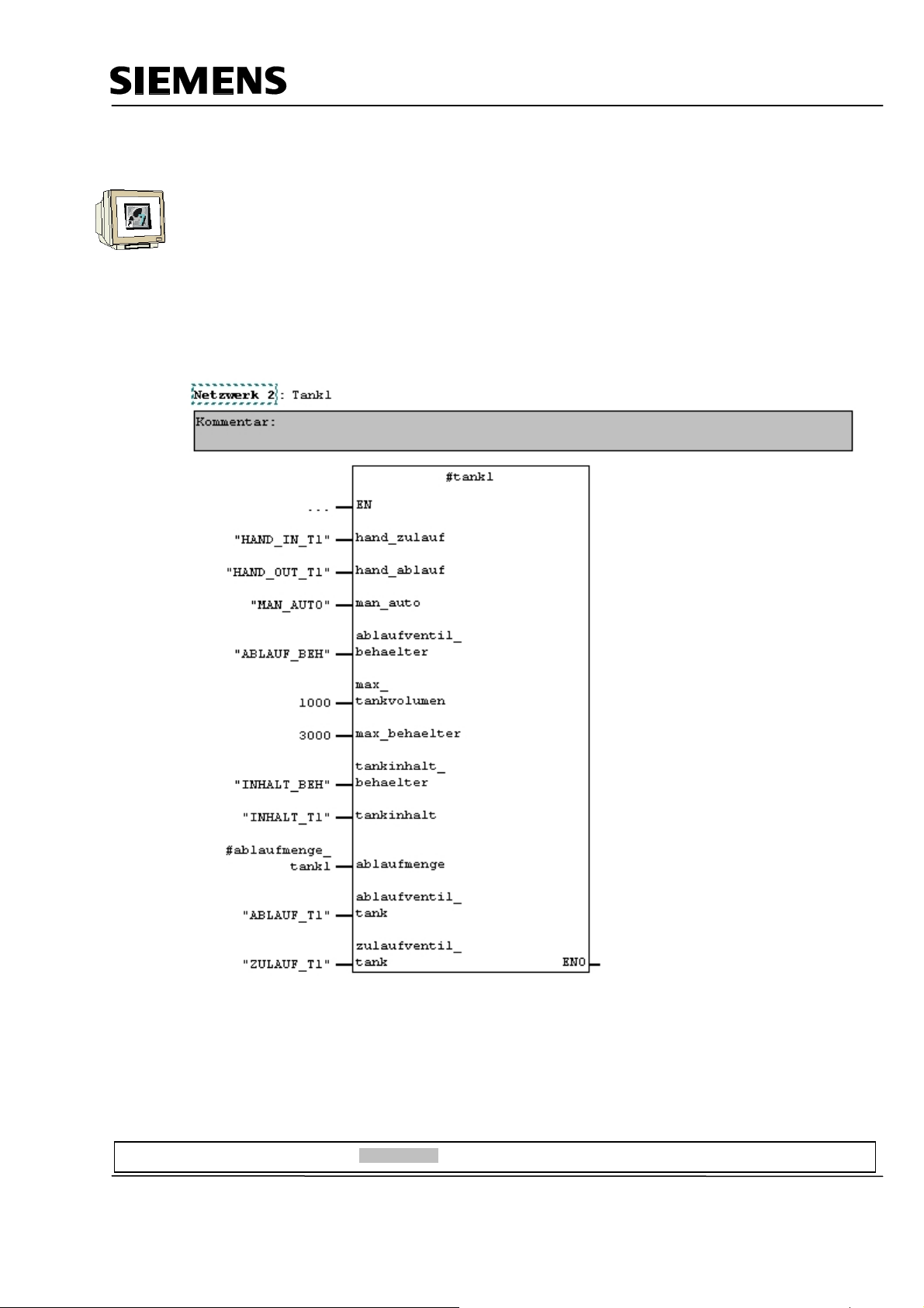
4.5.4 Tank Block FB10
Create a new network.
Drag the tank block FB10 from the library to Network 2.
Right click on the inserted block.
Select “Change to multi-instance call“
Enter the name “tank1“.
Confirm with OK.
This block contains the two step control and the calculations for simulating the level. When level
sensors are used, only the two step control would be necessary. Wire the block’s inputs.
Preface Installation Project Description Step7 Projekt HMI Station WinCC flexible Project Messages Recipes User Management
T I A Training Document Page 26 of 129 Module
F6
Issued: 02/2008 Operator Control with WinCC flexible 2005
Page 27
Automation and Drives - SCE
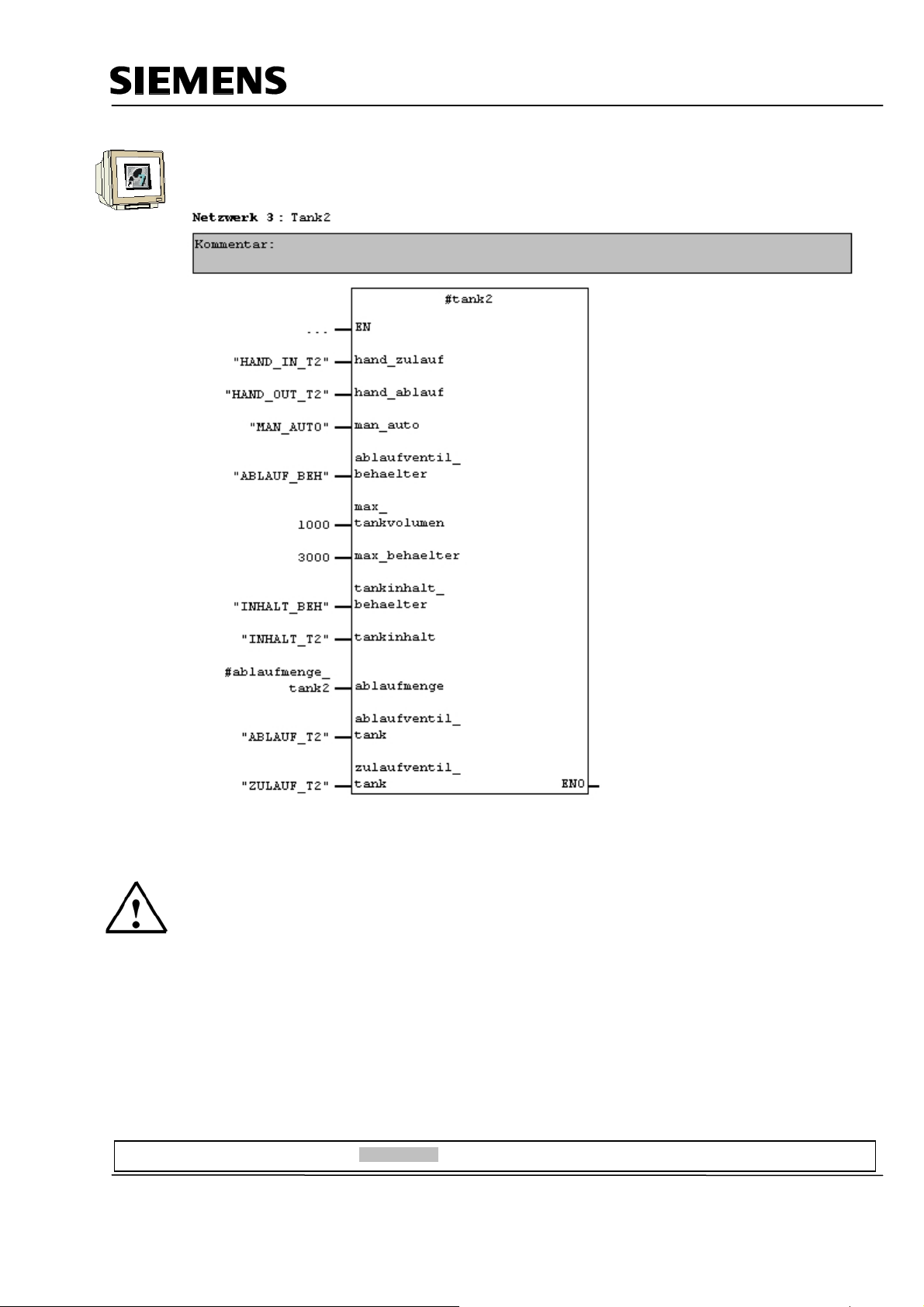
Repeat the steps for Tank2 in Network 3.
Note
Writing the symbolic names in “CAPITALS“ and the variables in “lower case letters“ makes better
assignments possible.
Preface Installation Project Description Step7 Projekt HMI Station WinCC flexible Project Messages Recipes User Management
T I A Training Document Page 27 of 129 Module
F6
Issued: 02/2008 Operator Control with WinCC flexible 2005
Page 28
Automation and Drives - SCE
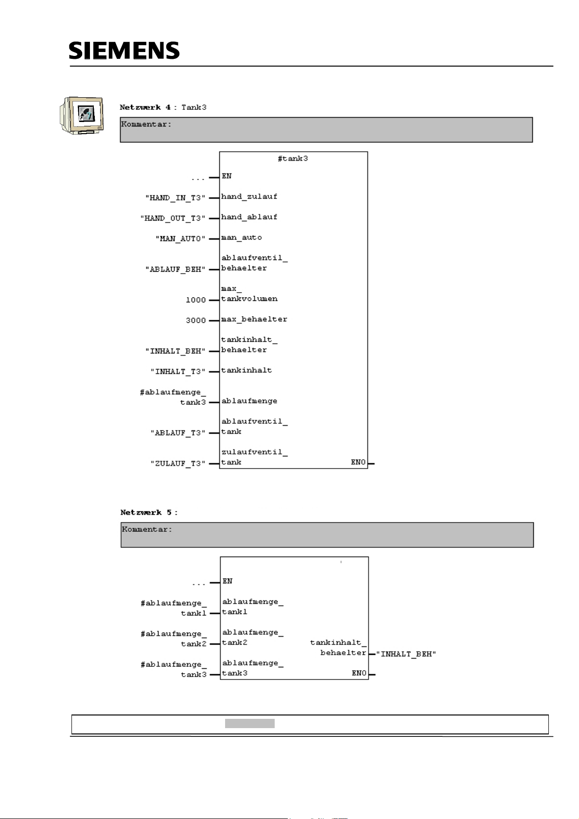
Repeat the steps for Tank3 in Network 4.
Create a new network and drag tank block FC10 from the library to Network 5.
Calculating the container level
Container Level
Preface Installation Project Description Step7 Projekt HMI Station WinCC flexible Project Messages Recipes User Management
T I A Training Document Page 28 of 129 Module
F6
Issued: 02/2008 Operator Control with WinCC flexible 2005
Page 29
Automation and Drives - SCE
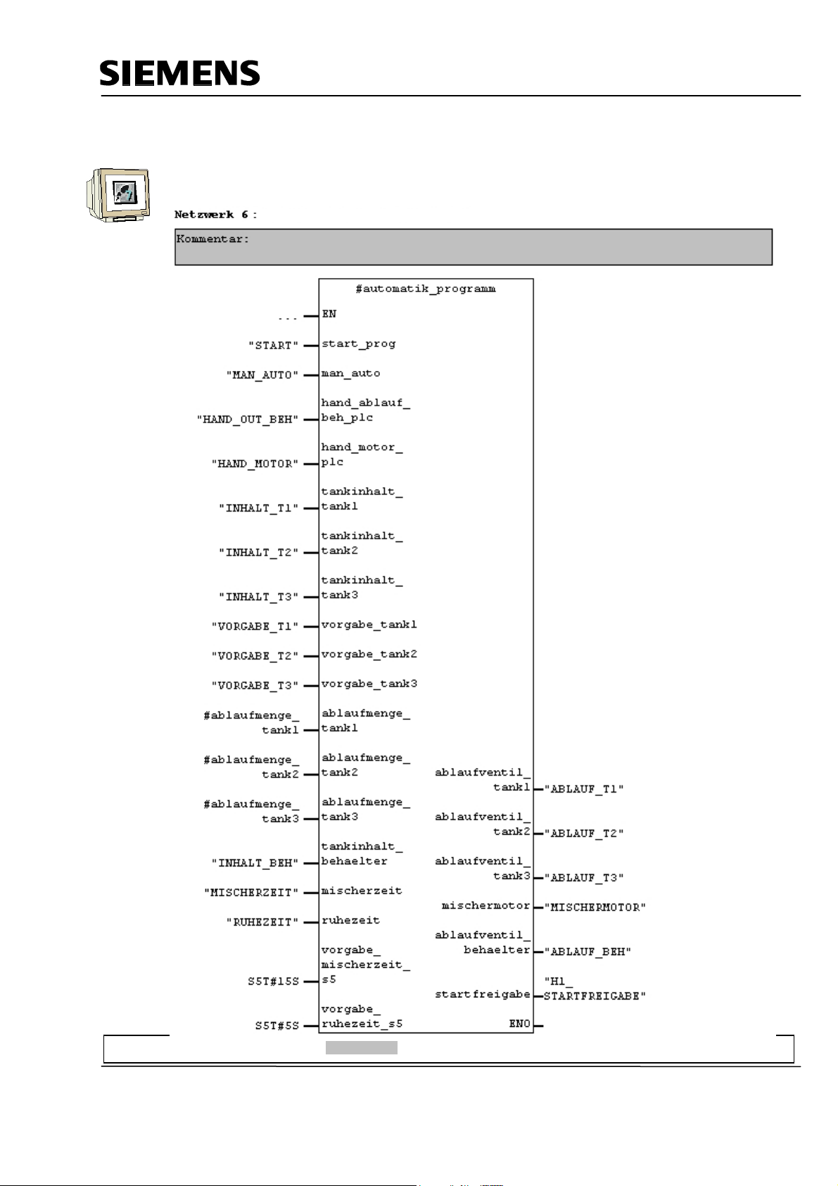
4.5.5 Automatic Program Sequence FB15
The automatic program sequence is described in the plant description.
Automatic Program Sequence
Preface Installation Project Description Step7 Projekt HMI Station WinCC flexible Project Messages Recipes User Management
T I A Training Document Page 29 of 129 Module
F6
Issued: 02/2008 Operator Control with WinCC flexible 2005
Page 30
Automation and Drives - SCE
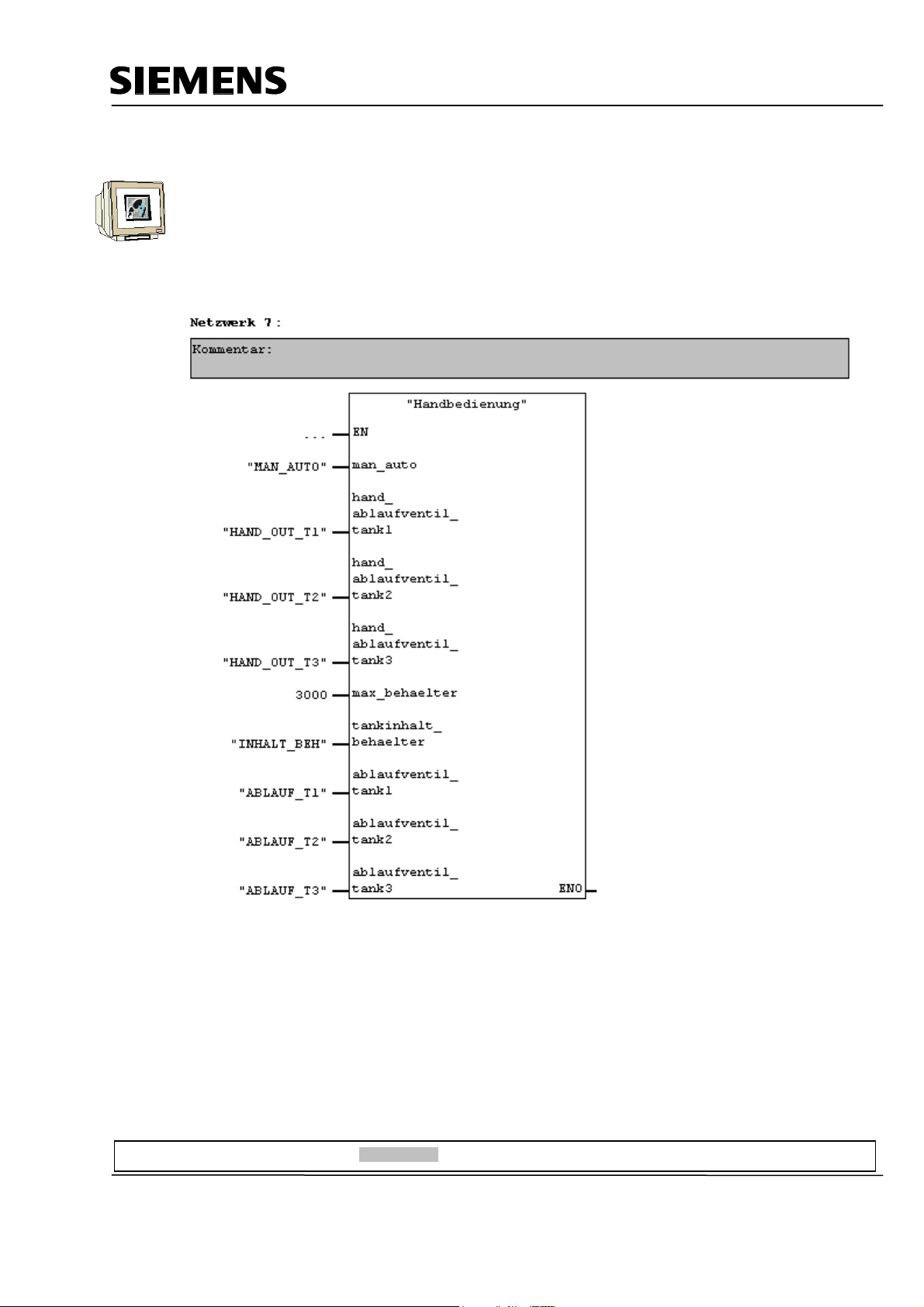
4.5.6 Manual Operation FC20
Create a new network and drag the FC20 from the library to Network 7.
This block contains the manual operation of the tanks’ outflow valves in the manual mode.
This FC20 has to be called after the FB15, since the automatic valve operations of the FB15 have to
be overwritten by the manual mode in FC20.
Wire the inputs of the block.
Manual mode of the outflow valves of the tanks
Preface Installation Project Description Step7 Projekt HMI Station WinCC flexible Project Messages Recipes User Management
T I A Training Document Page 30 of 129 Module
F6
Issued: 02/2008 Operator Control with WinCC flexible 2005
Page 31

Automation and Drives - SCE
4.5.7 Mixer Motion FB25
This block is necessary to simulate the mixer motion. When the mixer motor is in operation, a count
in 150ms cycles, of the value 0 to 12 is incremented.
Simulate mixer motion
4.5.8 Automatic and Manual Lamps
In the last FB1 network, assignments for the automatic and manual lamps are generated.
Assign authomatic and manual lamp
FB1 is now completed.
Save and Close FB1.
Preface Installation Project Description Step7 Projekt HMI Station WinCC flexible Project Messages Recipes User Management
T I A Training Document Page 31 of 129 Module
F6
Issued: 02/2008 Operator Control with WinCC flexible 2005
Page 32

Automation and Drives - SCE
4.5.9 Organization Block OB1
Open OB1 by double clicking on it.
Drag FB1 from the folder “FB Blocks“ to Network 1 for the control program
Enter DB1 as instance data block.
In the message window, click on the button “Yes“.
OB1 is now complete.
Save and Close OB1.
Preface Installation Project Description Step7 Projekt HMI Station WinCC flexible Project Messages Recipes User Management
T I A Training Document Page 32 of 129 Module
F6
Issued: 02/2008 Operator Control with WinCC flexible 2005
Page 33

Automation and Drives - SCE
4.6 Loading to the CPU
The control program for the color mixing plant is not completed.
In the project window, highlight the folder Blocks and then click on the button “Load“
4.7 Program Test
After loading the control program to the CPU, switch the controller to the RUN mode.
Test your program. For example, at the tank blocks, you can monitor the levels.
With “Monitor/control variables“, you can enter levels (MW120 to MW124).
Preface Installation Project Description Step7 Projekt HMI Station WinCC flexible Project Messages Recipes User Management
T I A Training Document Page 33 of 129 Module
F6
Issued: 02/2008 Operator Control with WinCC flexible 2005
Page 34

Automation and Drives - SCE
5 SIMATIC HMI STATION
5.1 Inserting an HMI Station
In your project window, highlight the project name “Color mixing plant“ (Farbmischanlage) and insert
a SIMATIC HMI station.
Preface Installation Project Description Step7 Project HMI Station WinCC flexible Project Messages Recipes User Management
T I A Training Document Page 34 of 129 Module
F6
Issued: 02/2008 Operator Control with WinCC flexible 2005
Page 35

Automation and Drives - SCE
The properties of WinCC flexible RT are opened.
As device type, select TP 177B color PN/DP.
Confirm with OK.
SIMATIC WinCC flexible ES is started and a SIMATIC HMI station is inserted.
Preface Installation Project Description Step7 Project HMI Station WinCC flexible Project Messages Recipes User Management
T I A Training Document Page 35 of 129 Module
F6
Issued: 02/2008 Operator Control with WinCC flexible 2005
Page 36

Automation and Drives - SCE
5.2 Configuring the HMI Station
At the inserted SIMATIC HMI station, click on Configuration.
Connect the SIMATIC HMI station with the MPI network.
Click on Save and Compile.
Close the configuration.
Note
In the WinCC flexible project, a connection via the MPI is generated automatically.
Preface Installation Project Description Step7 Project HMI Station WinCC flexible Project Messages Recipes User Management
T I A Training Document Page 36 of 129 Module
F6
Issued: 02/2008 Operator Control with WinCC flexible 2005
Page 37

Automation and Drives - SCE
5.3 Checking the Connection with NetPro
Start NetPro by clicking on the button in the SIMATIC Manager.
Here, you can check the communication connections very easily.
Also, you can make changes or corrections subsequently with NetPro.
With a double click, the module’s properties are opened.
IMPORTANT NOTE
NetPro, the hardware configuration, and WinCC flexible access a joint data base and must not be
opened at the same time.
If one of these programs is opened, only reading functions are often possible in the next program.
The advantage is that a change of the MPI address, for example, is accepted in all programs.
Preface Installation Project Description Step7 Project HMI Station WinCC flexible Project Messages Recipes User Management
T I A Training Document Page 37 of 129 Module
F6
Issued: 02/2008 Operator Control with WinCC flexible 2005
Page 38

Automation and Drives - SCE
5.4 Opening the HMI Station
Right click on “WinCC flexible RT“ and select Open Object.
Preface Installation Project Description Step7 Project HMI Station WinCC flexible Project Messages Recipes User Management
T I A Training Document Page 38 of 129 Module
F6
Issued: 02/2008 Operator Control with WinCC flexible 2005
Page 39

Automation and Drives - SCE
6 WINCC FLEXIBLE ENGINEERING SYSTEM
6.1 Program Interface
The work environment of WinCC flexible consists of several elements. Some of these elements are
coupled to certain editors and are visible only if the corresponding editor is active.
WinCC flexible consists of the following elements:
Menu Bar Symbol Bar Tool Window
Output Window
Project Window
Object Window
Work Area
Library
Property Window
Preface Installation Project Description Step7 Project HMI Station WinCC flexible Projekt Messages Recipes User Management
T I A Training Document Page 39 of 129 Module
F6
Issued: 02/2008 Operator Control with WinCC flexible 2005
Page 40

Automation and Drives - SCE
6.1.1 Menus and Symbol Bars
The menus and the symbol bars contain all the functions you need to configure your operator panel.
If a corresponding editor is active, menu commands or symbol bars are visible specific to the editor.
If you point to a command with the mouse pointer, you will get a corresponding QuickInfo for each
function.
When a new project is set up, the symbol bars are positioned at the upper screen boundary as a
matter of standard. The position of the symbol bars is coupled to the user that is signed on in
Windows. If you have moved symbol bars with the mouse, the positions that the symbol bars had at
the last close are restored after starting WinCC flexible.
The following menus are available in WinCC flexible:
The availability of the menus and their instruction set depends on the editor that is used.
Preface Installation Project Description Step7 Project HMI Station WinCC flexible Projekt Messages Recipes User Management
T I A Training Document Page 40 of 129 Module
F6
Issued: 02/2008 Operator Control with WinCC flexible 2005
Page 41

Automation and Drives - SCE
6.1.2 Work Space
In the work space, the objects of the project are edited. All elements of WinCC flexible are arranged
around the work space. Except for the work space, you can arrange and configure all elements
according to your own requirements; for example, shifting or hiding.
In the work space, project data is edited either in table form (for example, variables) or graphically
(for example, a process image). Each opened editor is represented in the work space on its own tab
sheet. For graphic editors, each element is represented by a separate tab sheet. If you have several
editors opened at the same time, only one tab sheet is active. To switch to another editor, click on
the corresponding register sheet. You can have a maximum of 20 editors opened at the same time.
Preface Installation Project Description Step7 Project HMI Station WinCC flexible Projekt Messages Recipes User Management
T I A Training Document Page 41 of 129 Module
F6
Issued: 02/2008 Operator Control with WinCC flexible 2005
Page 42

Automation and Drives - SCE
6.1.3 Project Window
The project window is the central control point for project processing. All constituent parts and all
available editors of a project are displayed as a tree structure in the project window and can be
opened from there. To each editor, a symbol is assigned. With it, you can identify the associated
objects. Only those elements are displayed in the project window that the selected operator panel
supports. In the project window, you can access the device settings of the operator panel, language
support, and version management.
The project window represents the structure of the project hierarchically
• Project
• Operator panels
• Folders
• Objects
In the project window, objects are set up and opened for processing. You can set up folders to
structure the objects of your project. The project window is operated similar to the Windows
Explorer. For all objects, you can call a context menu where the most important commands are
combined.
Elements of graphic editors are shown in the project window and in the object window. Elements of
tabular editors are displayed only in the object window.
Preface Installation Project Description Step7 Project HMI Station WinCC flexible Projekt Messages Recipes User Management
T I A Training Document Page 42 of 129 Module
F6
Issued: 02/2008 Operator Control with WinCC flexible 2005
Page 43

Automation and Drives - SCE
6.1.4 Property Window
In the property window, the properties of objects are edited; for example, the color of picture objects.
The property window is available only in certain editors.
In the property window, the properties of the selected object, arranged by categories, are displayed.
As soon as you exit an input field, the values that were changed are effective.
If you enter an invalid value, it is displayed with a background color.
Using QuickInfo, information is provided about the valid value range, for example.
IMPORTANT NOTE
The inputs in the property window are not accepted by operating the input key, but by exiting the
field, or by clicking on another field. Please note where you are clicking after making inputs via the
keyboard. Otherwise, you will possibly be changing to the properties of the selected object, or a
check mark is placed in a check box in the property window, since the area of focus is very large.
Preface Installation Project Description Step7 Project HMI Station WinCC flexible Projekt Messages Recipes User Management
T I A Training Document Page 43 of 129 Module
F6
Issued: 02/2008 Operator Control with WinCC flexible 2005
Page 44

Automation and Drives - SCE
6.1.5 Tool Window
The tool window provides you with a selection of objects that you can insert in your pictures; for
example, graphic objects and control elements. In addition, the tool window includes libraries with
completed library objects, and collections of picture blocks.
Preface Installation Project Description Step7 Project HMI Station WinCC flexible Projekt Messages Recipes User Management
T I A Training Document Page 44 of 129 Module
F6
Issued: 02/2008 Operator Control with WinCC flexible 2005
Page 45

Automation and Drives - SCE
6.1.6 Output Window
In the output window, system messages are displayed standard in the sequence in which they occur.
The categories identify each WinCC flexible submodule that generated a system message. System
messages of the category "Generator" are generated, for example, during the consistency check.
To arrange the system messages, click on the header of the corresponding column. The output
window displays all system messages of the last action. If there is a new action, all previous system
messages are overwritten.
To provide continued access to existing system messages, they are stored in a separate log file.
Errors -for example, during generation- are displayed in color and can be selected by using the
context menu. You can jump to an error location or to a variable, copy system messages, or clear
them.
6.1.7 Object Window
In the object window, the contents of the folders in the project window are displayed.
The object window can be displayed permanently by docking it onto or shifting it into the project
window.
6.1.8 Resetting the Arrangement
In the menu “View“, click on “Reset arrangement“.
Preface Installation Project Description Step7 Project HMI Station WinCC flexible Projekt Messages Recipes User Management
T I A Training Document Page 45 of 129 Module
F6
Issued: 02/2008 Operator Control with WinCC flexible 2005
Page 46

Automation and Drives - SCE
6.2 Configuring Displays
A display can consist of static and dynamic parts. The controller does not update static parts, such
as texts and graphics.
Dynamic parts are connected to the controller, and visualize current values from the controller’s
memory. Visualization can be in the form of alpha-numerical displays, curves, and bars. Dynamic
parts also consist of inputs made at the OP that are written to the controller’s memory. They are
interfaced with the controller by means of Variables.
For our color mixing plant, five displays are to be generated initially.
Display Template
This display is set up automatically, and contains central functions.
In the upper area of the display, a permanent window is generated. Here, the levels of the tanks, of
the container and the project name are shown.
In the lower area of the display, the message window and the message indicator are shown. These
objects are also embedded in all displays, and are opened in the display’s foreground if there is a
message, for example.
Basic Display
This display also is set up automatically, and it is also defined as start picture. Here, the entire plant
is shown
Changing the operating mode, starting the mixing process, operating the mixer motor manually, and
opening the outflow valve can be performed by means of buttons. The motion of the mixer and the
states of the valves are shown graphically. By means of input fields, the amounts of the individual
additives are specified. In addition, it is to be possible to jump to the other displays. Using the button
END, the runtime at the panel is terminated, and a new transfer can be made.
Tank1
In the third picture, the valves of Tank1 can be operated manually. The maximum and minimum
amount of filling has to be preset at linear regulators. By means of buttons (Open valve), the inflow
and outflow valve can be opened or closed. The valves are shown graphically, and change color
when they are open.
The level is indicated in red. If the maximum level is reached, the inflow valve is closed in the
automatic mode. When the tank is completely full, the inflow valve can not be opened.
With additional buttons, you can switch to the other tanks, or to the basic display.
Tank2, Tank3
The displays for Tank2 and Tank3 are structured exactly like the display for Tank1.
The valves and the level of Tank2 are colored green.
The valves and the level of Tank3 are colored blue.
Preface Installation Project Description Step7 Project HMI Station WinCC flexible Projekt Messages Recipes User Management
T I A Training Document Page 46 of 129 Module
F6
Issued: 02/2008 Operator Control with WinCC flexible 2005
Page 47

Automation and Drives - SCE
6.2.1 Display Template
Specifying the permanent area, and changing the background color.
With a double click on Template, open the display Template in the project window.
Drag the bar in the upper area of the panel display window a little downward.
Change the background color in the property window for the permanent area to yellow.
Change the background color in the property window for the work area to white.
Note
If you open the Settings in the menu Options and display the Grid (Raster anzeigen), you can set
the permanent window to a size of 32 pixels.
Preface Installation Project Description Step7 Project HMI Station WinCC flexible Projekt Messages Recipes User Management
T I A Training Document Page 47 of 129 Module
F6
Issued: 02/2008 Operator Control with WinCC flexible 2005
Page 48

Automation and Drives - SCE
Inserting a text field
Drag and drop a text field from the tool window to the permanent window.
For the properties in the text field, enter “Color mixing plant“.
Caution! Do not press the input key.
Under Properties, click on Representation and remove the checkmark adjust automatically.
Change the size and the position of the text field.
Preface Installation Project Description Step7 Project HMI Station WinCC flexible Projekt Messages Recipes User Management
T I A Training Document Page 48 of 129 Module
F6
Issued: 02/2008 Operator Control with WinCC flexible 2005
Page 49

Automation and Drives - SCE
Under Properties, click on Text and
change the font size and the text orientation.
Inserting the date and time of day field
Drag a date/time of day field from the tool window and drop it in the permanent window.
Preface Installation Project Description Step7 Project HMI Station WinCC flexible Projekt Messages Recipes User Management
T I A Training Document Page 49 of 129 Module
F6
Issued: 02/2008 Operator Control with WinCC flexible 2005
Page 50

Automation and Drives - SCE
Under Properties, change the style of the fill type to “Transparent“
Under Properties, click on Representation and remove the check mark Adjust automatically.
Change the size and the position.
Under Properties, click on Text.
Change the font size and the orientation of the text.
For the time being, the display Template is completed.
Note
Now and then, you should save your project by clicking on the diskette symbol.
Preface Installation Project Description Step7 Project HMI Station WinCC flexible Projekt Messages Recipes User Management
T I A Training Document Page 50 of 129 Module
F6
Issued: 02/2008 Operator Control with WinCC flexible 2005
Page 51

Automation and Drives - SCE
6.2.2 Generating Displays
In the project window, right click on Display1 and select Rename.
Enter “Basic display“ as the name for the picture.
Double click on Add picture and assign the name “Tank1“.
Generate the pictures for Tank2 and Tank3 also.
For all pictures, change the background color of the work area to white. To do this, click on the tabs
of the figures.
Preface Installation Project Description Step7 Project HMI Station WinCC flexible Projekt Messages Recipes User Management
T I A Training Document Page 51 of 129 Module
F6
Issued: 02/2008 Operator Control with WinCC flexible 2005
Page 52

Automation and Drives - SCE
6.2.3 Inserting Graphic Displays
Drag a graphic display to the work area of the basic figure.
In the property window of the graphic display, graphics can now be selected from the list. Using the
buttons, you can create new graphics from files or from OLE objects. You can also delete graphics
from the list.
The selected graphic appears in the preview window, and has to be inserted or removed with the
button Select or Deselect.
Double clicking on the graphic opens the graphics program.
Preface Installation Project Description Step7 Project HMI Station WinCC flexible Projekt Messages Recipes User Management
T I A Training Document Page 52 of 129 Module
F6
Issued: 02/2008 Operator Control with WinCC flexible 2005
Page 53

Automation and Drives - SCE
Click on Generate new graphic from OLE object.
Select Generate from file and click on Browse.
Highlight the figure “Plant.bmp“ and click on Open.
In the window that follows, confirm your selection with OK.
Preface Installation Project Description Step7 Project HMI Station WinCC flexible Projekt Messages Recipes User Management
T I A Training Document Page 53 of 129 Module
F6
Issued: 02/2008 Operator Control with WinCC flexible 2005
Page 54

Automation and Drives - SCE
Under Representation, change the size and position of the graphic.
Repeat these steps for inserting the graphics in figures Tank1 to Tank3.
Under Representation, change the size and the position of the three inserted graphics.
Note
If a graphic is inserted by means of an OLE object, the file name is retained.
Don’t forget to save!
Preface Installation Project Description Step7 Project HMI Station WinCC flexible Projekt Messages Recipes User Management
T I A Training Document Page 54 of 129 Module
F6
Issued: 02/2008 Operator Control with WinCC flexible 2005
Page 55

Automation and Drives - SCE
6.2.4 Configuring Display Changes
By means of buttons, it is to be possible in each figure to change to the other three figures. In the
case of WinCC flexible, only the names of the figures have to be dragged from the project window to
the figure. The buttons are generated automatically.
Change the size and the position of the button.
Under text, select the font “Tahoma; 8pt“.
Repeat these steps for the buttons for Tank2 and Tank3.
In the tank figures, generate the buttons for the display change.
Change the width of the button “Basic display“ to 60.
You can also copy and insert prepared buttons.
Don’t forget to save!
Preface Installation Project Description Step7 Project HMI Station WinCC flexible Projekt Messages Recipes User Management
T I A Training Document Page 55 of 129 Module
F6
Issued: 02/2008 Operator Control with WinCC flexible 2005
Page 56

Automation and Drives - SCE
Basic Display
Figure Tank1
Preface Installation Project Description Step7 Project HMI Station WinCC flexible Projekt Messages Recipes User Management
T I A Training Document Page 56 of 129 Module
F6
Issued: 02/2008 Operator Control with WinCC flexible 2005
Page 57

Automation and Drives - SCE
Figure Tank2
Figure Tank3
Preface Installation Project Description Step7 Project HMI Station WinCC flexible Projekt Messages Recipes User Management
T I A Training Document Page 57 of 129 Module
F6
Issued: 02/2008 Operator Control with WinCC flexible 2005
Page 58

Automation and Drives - SCE
6.3 Settings at the Touch Panel TP177B color PN/DP
Before we can perform the first test, the settings on the touch panel have to be executed first.
The following settings have to be made:
- Setting the date and time of day
- Assigning the MPI or Profibus DP address
- Assigning the Ethernet address
- Setting the transfer properties
Touch Panel TP177B processes with the operating system Windows CE and can, like all touch
panels, be operated directly on the screen. For better operation, you should use a touch pen, or
connect a mouse at the panel’s USB interface.
After starting the panel, the desktop appears and the window of the loader. At the lower edge of the
screen, the start bar is located. With it, you can -just as with other Windows systems- start the
programs or make settings.
Buttons in the Loader:
Transfer: Data transfer becomes active, and data can be entered by WinCC flexible
Start: Runtime is started, and process visualization appears on the panel
Control Panel: The Windows CE desktop is called
Taskbar: The start bar is opened
Preface Installation Project Description Step7 Project HMI Station WinCC flexible Projekt Messages Recipes User Management
T I A Training Document Page 58 of 129 Module
F6
Issued: 02/2008 Operator Control with WinCC flexible 2005
Page 59

Automation and Drives - SCE
6.3.1 Setting the Date and the Time of Day
To set the date and the time of day, operate the button Control Panel.
This opens the desktop of Windows CE.
Select Date/Time to make the settings.
Set the time zone, the date and the time. Confirm with OK.
Preface Installation Project Description Step7 Project HMI Station WinCC flexible Projekt Messages Recipes User Management
T I A Training Document Page 59 of 129 Module
F6
Issued: 02/2008 Operator Control with WinCC flexible 2005
Page 60

Automation and Drives - SCE
6.3.2 Setting the MPI Address
To set the MPI address on the panel, click on “S7 Transfer Settings“
Select MPI and click on Properties.
Place a checkmark at “Panel is the only master on the bus“.
Assign the MPI Address 1 and confirm with OK.
Note
Many panels allow data transfers only if either the panel or the programmer is set as the only master
on the bus.
Preface Installation Project Description Step7 Project HMI Station WinCC flexible Projekt Messages Recipes User Management
T I A Training Document Page 60 of 129 Module
F6
Issued: 02/2008 Operator Control with WinCC flexible 2005
Page 61

Automation and Drives - SCE
6.3.3 Setting the Profibus DP Address
To set the Profibus DP address, click on “S7 Transfer Settings“ on the desktop.
Select Profibus and click on the button Properties.
Place the checkmark at “Panel is the only master on the bus“.
Assign the Profibus DP Address 1 and confirm with OK.
6.3.4 Assigning the Ethernet Address
On the desktop, operate the symbol
and select the Onboard LAN Ethernet Driver.
Click on the button Properties.
Here, you can make the settings for the Ethernet.
Preface Installation Project Description Step7 Project HMI Station WinCC flexible Projekt Messages Recipes User Management
T I A Training Document Page 61 of 129 Module
F6
Issued: 02/2008 Operator Control with WinCC flexible 2005
Page 62

Automation and Drives - SCE
6.3.5 Setting the Transfer Properties
On the desktop, click on the symbol
Select MPI/Profibus and click on the button Advanced.
In the window that follows, select MPI and confirm with OK.
Note
The settings at Transfer Settings have nothing to do with the connection settings in the
WinCC flexible project.
For example, data can be transferred between Panel TP177B and WinCC flexible by means of the
Ethernet interface, and the panel and the SIMATIC S7 controller can communicate by means of the
MPI.
6.3.6 Transfer Mode
Close the desktop and switch the panel to the Transfer Mode.
Connecting to host … appears in the transfer window.
Preface Installation Project Description Step7 Project HMI Station WinCC flexible Projekt Messages Recipes User Management
T I A Training Document Page 62 of 129 Module
F6
Issued: 02/2008 Operator Control with WinCC flexible 2005
Page 63

Automation and Drives - SCE
6.4 Checking for Consistency
Before you transfer the WinCC flexible project to the panel, the consistency should be checked. The
project is checked and generated.
Click on Consistency check of the project.
The result is displayed in the output window.
6.5 Transfer Settings and Data Transfer under WinCC flexible
In WinCC flexible, the settings have to be made for the transfer. Click on the button Settings for the
Transfer.
For Mode, select MPI/DP; enter 1 as station address.
Click on Transfer.
Preface Installation Project Description Step7 Project HMI Station WinCC flexible Projekt Messages Recipes User Management
T I A Training Document Page 63 of 129 Module
F6
Issued: 02/2008 Operator Control with WinCC flexible 2005
Page 64

Automation and Drives - SCE
Confirm overwriting the keyword list.
<<Do you want to overwrite the existing keyword list on the operator panel?>>
If the transfer settings are correct on the panel and in WinCC flexible, the transfer starts now.
After restarting the panel, the start picture appears in runtime.
Test all buttons for the display change.
Preface Installation Project Description Step7 Project HMI Station WinCC flexible Projekt Messages Recipes User Management
T I A Training Document Page 64 of 129 Module
F6
Issued: 02/2008 Operator Control with WinCC flexible 2005
Page 65

Automation and Drives - SCE
6.6 Button END
The project can only be transferred again if the panel TP177B is in the transfer mode. When the
panel powers up, the loader appears for a few seconds with the button “Transfer“. Before each
transfer, the panel would have to be taken off load so that a switchover to the transfer mode is
possible. Data is lost in that case; for example, the date and the time of day have to be reset.
For that reason, in our basic display we are creating a button for ending the runtime mode. Drag a
button into your basic display.
Change the text, the font size, the size 40 x 20, the position and the color (red) of the button.
Preface Installation Project Description Step7 Project HMI Station WinCC flexible Projekt Messages Recipes User Management
T I A Training Document Page 65 of 129 Module
F6
Issued: 02/2008 Operator Control with WinCC flexible 2005
Page 66

Automation and Drives - SCE
Under Events, select the function StopRuntime by Clicking on the function.
A configured function is referred to in bold print.
Under mode, other settings can be made.
For our panel TP177B, only Runtime is to be terminated.
Save your project and start the consistency check.
Note
If during the consistency check, lines that are marked blue that contain internal warnings occur, you
have to regenerate the entire project first.
In the menu “Project“, click on Generator and select Regenerate everything.
Perform a restart at the panel (take it briefly off load).
Switch the panel to the transfer mode.
Transfer your project to the panel.
Click on the END button
Reset the date and the time, and start Runtime.
Preface Installation Project Description Step7 Project HMI Station WinCC flexible Projekt Messages Recipes User Management
T I A Training Document Page 66 of 129 Module
F6
Issued: 02/2008 Operator Control with WinCC flexible 2005
Page 67

Automation and Drives - SCE
6.7 Configuring a Connection
So far, we worked in our project without accessing the SIMATIC S7 controller.
On our panel, levels are to be displayed and fill setpoints are to be entered.
For operator and display objects that access the process values of a controller, first the connection
to the controller has to be configured.
Here, you specify how and by means of what interface the panel communicates with the controller.
Double click on the window Connections.
All parameters are already set through the settings in the hardware configuration.
Note
To set up a new connection, double click in the free field in the first column. Change the connection
parameters of the newly created connection
Preface Installation Project Description Step7 Project HMI Station WinCC flexible Projekt Messages Recipes User Management
T I A Training Document Page 67 of 129 Module
F6
Issued: 02/2008 Operator Control with WinCC flexible 2005
Page 68

Automation and Drives - SCE
7 DISPLAY AND OPERATOR OBJECTS
Display and operator objects are graphic elements with which process displays are designed.
In Runtime, all display and operator objects behave dynamically.
In addition, you can make the properties of objects dynamic.
One example of this is the graphic of a tank whose liquid level is displayed as varying, depending on
the corresponding process value.
Another example for the dynamic behavior of an object is a button that triggers a certain function. In
principle, you can make all graphic objects dynamic.
You can configure the following:
- The object changes its appearance: color and blinking.
- The object moves in the picture.
- The object is inserted/removed.
For operator elements, you can configure the following:
- The object is enabled or disabled for operation.
- By operating the object -for example, by clicking on it- an event is triggered to which the
processing of a function list is configured.
7.1 Levels
For differentiated representation of a picture and for editing the objects in it, levels and multi- layering
of the objects are provided.
A picture has 32 levels. You can insert objects in each level. The assignment to a level specifies
the depth of the layer of an object in the picture. Objects of Level 0 are located deep in the
background of the picture, objects of Level 31 in the very foreground.
In addition, objects in a single level are also staggered.
When creating a process image, the objects of an individual level are -by default- arranged in the
sequence in which they were configured. Within the level, the object that was inserted first is located
at the very back. Each additional object is inserted one position ahead of it. The position of the
objects in relation to each other can be changed within the level. There is always an active level.
When you insert objects in a figure, they are assigned to the active level by default. The number of
the active level is indicated in the symbol bar "Level".
In the level palette, the active level is highlighted in color.
When you open a picture, all its 32 levels are always displayed.
With the level palette, you can hide, after opening, all levels except for the active level. This allows
you to specifically edit the objects in the active level.
Preface Installation Project Description Step7 Project HMI Station WinCC flexible Project Messages Recipes User Management
T I A Training Document Page 68 of 129 Module
F6
Issued: 02/2008 Operator Control with WinCC flexible 2005
Page 69

Automation and Drives - SCE
7.2 Basic Objects
Preface Installation Project Description Step7 Project HMI Station WinCC flexible Project Messages Recipes User Management
T I A Training Document Page 69 of 129 Module
F6
Issued: 02/2008 Operator Control with WinCC flexible 2005
Page 70

Automation and Drives - SCE
Note
Depending on the operator panel for which you are configuring, some objects from the tool window
are not available, or only with limited modes of operation.
Objects that are not available are displayed in the tool window grayed, and can not be selected.
Preface Installation Project Description Step7 Project HMI Station WinCC flexible Project Messages Recipes User Management
T I A Training Document Page 70 of 129 Module
F6
Issued: 02/2008 Operator Control with WinCC flexible 2005
Page 71

Automation and Drives - SCE
7.3 Expanded Objects
Preface Installation Project Description Step7 Project HMI Station WinCC flexible Project Messages Recipes User Management
T I A Training Document Page 71 of 129 Module
F6
Issued: 02/2008 Operator Control with WinCC flexible 2005
Page 72

Automation and Drives - SCE
8 DISPLAY AND OPERATOR OBJECTS IN THE PROJECT "COLOR MIXING PLANT“
8.1 Configuring Display and Operator Objects in the Picture“Tank1“
First, a bar, two sliders (linear regulators), and two buttons are configured.
8.1.1 Configuring the Bar Display
To display the current level of Tank1, we configure a bar.
Drag a bar into the picture Tank1.
Preface Installation Project Description Step7 Project HMI Station WinCC flexible Project Messages Recipes User Management
T I A Training Document Page 72 of 129 Module
F6
Issued: 02/2008 Operator Control with WinCC flexible 2005
Page 73

Automation and Drives - SCE
As a Maximum Value, enter 1000.
From the symbols of the color mixing plant, select the variable “CONTENT_T1“ as process variable.
The WinCC flexible variable “CONTENT_T1“ was generated automatically as process variable.
By double clicking on Variables in the project window, additional settings can be made.
Change the data collection cycle of the variable to 100ms. The variable will now be updated every
100ms.The movement of the bar -that is, the tank level- is now shown as flowing.
Note
Communication influences the cycle time of the SIMATIC S7 300 controller. If there is a large
number of variables, the data collection cycle of each variable should be weighed carefully.
Preface Installation Project Description Step7 Project HMI Station WinCC flexible Project Messages Recipes User Management
T I A Training Document Page 73 of 129 Module
F6
Issued: 02/2008 Operator Control with WinCC flexible 2005
Page 74

Automation and Drives - SCE
In the property window, under Style (Gestaltung), change the color assignments of the foreground
color to red and the background of the bar to white.
At Scale, remove the check mark “Display scale“ (Skala anzeigen).
At the limits, remove the check mark for “Display limit lines“ (Grenzwertlinien anzeigen).
Preface Installation Project Description Step7 Project HMI Station WinCC flexible Project Messages Recipes User Management
T I A Training Document Page 74 of 129 Module
F6
Issued: 02/2008 Operator Control with WinCC flexible 2005
Page 75

Automation and Drives - SCE
At Representation, change the position and the size of the bar.
Bar direction is already preset to UP (Oben).
The bar for indicating the level in the picture Tank1 is now completed.
Preface Installation Project Description Step7 Project HMI Station WinCC flexible Project Messages Recipes User Management
T I A Training Document Page 75 of 129 Module
F6
Issued: 02/2008 Operator Control with WinCC flexible 2005
Page 76

Automation and Drives - SCE
8.1.2 Configuring the Slider (Linear Regulator)
To set the minimum level, we are configuring a slider. From the tool window under Expanded
Objects, drag the Slider into the picture “Tank1“.
As the maximum value, enter 450, as the minimum value, enter 10 and select as process variable
the variable “low_level“ from the FB call “tank1“ of DB1 of the color mixing plant.
Note
Under WinCC flexible, you can also access the variable declaration in a data block.
Preface Installation Project Description Step7 Project HMI Station WinCC flexible Project Messages Recipes User Management
T I A Training Document Page 76 of 129 Module
F6
Issued: 02/2008 Operator Control with WinCC flexible 2005
Page 77

Automation and Drives - SCE
At Design, enter “MIN“ for labeling.
At Representation, change the position and the size of the slider.
At text, change the font size.
Insert a second slider for setting the maximum level in Tank1. Change the Minimum Value to 550,
the Maximum Value to 990, and select the variable “high_level“ as process variable from the FB call
“tank1“ of DB1.
For labeling, enter “MAX“ at Design.
Position the slider on X244 and Y32 and change the size to 64 x 152.
Finally, change the font size at Text.
Preface Installation Project Description Step7 Project HMI Station WinCC flexible Project Messages Recipes User Management
T I A Training Document Page 77 of 129 Module
F6
Issued: 02/2008 Operator Control with WinCC flexible 2005
Page 78

Automation and Drives - SCE
The picture Tank1 now looks like this.
In the meantime, three variables were set up automatically. If there should be additional variables,
highlight the line and delete the variable (right mouse key).
Don’t forget to save!
Preface Installation Project Description Step7 Project HMI Station WinCC flexible Project Messages Recipes User Management
T I A Training Document Page 78 of 129 Module
F6
Issued: 02/2008 Operator Control with WinCC flexible 2005
Page 79

Automation and Drives - SCE
8.1.3 Configuring a Button
To open the valves, we are configuring a button.
From the tool window under Basic Objects, drag a Button into the picture “Tank1“.
In General, place a check mark at Text EIN (open inflow valve) and enter the texts.
Caution! Don’t press the enter key after entering the text; otherwise, a new line is generated.
Preface Installation Project Description Step7 Project HMI Station WinCC flexible Project Messages Recipes User Management
T I A Training Document Page 79 of 129 Module
F6
Issued: 02/2008 Operator Control with WinCC flexible 2005
Page 80

Automation and Drives - SCE
Change the background color to white, and select a smaller font size.
Set the position and the size.
In the function list, at Drücken (Press), select the function “SetzeBit“ (set bit).
From DB1, select as variable “hand_zulauf_tank1“ (manual inflow tank1).
Preface Installation Project Description Step7 Project HMI Station WinCC flexible Project Messages Recipes User Management
T I A Training Document Page 80 of 129 Module
F6
Issued: 02/2008 Operator Control with WinCC flexible 2005
Page 81

Automation and Drives - SCE
We want to generate the function of a button; for that reason, configure now the function
“RuecksetzeBit“ (reset bit) with the variable “hand_zulauf_tank1“ at Loslassen (releasing) the
button.
The button is to be operable only in the manual mode.
Under Animations, select Operability.
Set the check mark at Activated.
From the symbols, select “H3_MAN“ as variable.
Enter 1 at “From“ and 1 at “To“.
Set the status to Activated.
The button can only be operated if the variable “H3_MAN“ has the value 1.
For operability (Bedienbarkeit) to be visible, change the background color to Blue at Style
(Gestaltung).
Preface Installation Project Description Step7 Project HMI Station WinCC flexible Project Messages Recipes User Management
T I A Training Document Page 81 of 129 Module
F6
Issued: 02/2008 Operator Control with WinCC flexible 2005
Page 82

Automation and Drives - SCE
Copy and insert the button.
Change the text to “Ablaufventil“ (outflow valve), the position to X80, Y158.
Under Ereignisse (events) Drücken and Loslassen (press and release), select the variable
“hand_ablauf_tank1“ (manual outflow Tank1).
In our variable list, only three additional variables were set up automatically.
Preface Installation Project Description Step7 Project HMI Station WinCC flexible Project Messages Recipes User Management
T I A Training Document Page 82 of 129 Module
F6
Issued: 02/2008 Operator Control with WinCC flexible 2005
Page 83

Automation and Drives - SCE
8.1.4 Showing the Valve Function in Color
The switching states of the valves are to be visible by changing color.
To this end, first set the zoom factor of the view to 400% and select the picture excerpt of the valve.
Then, in the tool window, highlight the Polygon.
.
Trace the valve by clicking on each corner, and by double clicking at the end.
Because of the grid function, the polygon is a little larger than it is in the graphic.
The size and the position will be adjusted in the Properties.
Preface Installation Project Description Step7 Project HMI Station WinCC flexible Project Messages Recipes User Management
T I A Training Document Page 83 of 129 Module
F6
Issued: 02/2008 Operator Control with WinCC flexible 2005
Page 84

Automation and Drives - SCE
Change the position and the size in a way so that the graphic and the polygon fit together.
In the Properties at Style, change the fill color to yellow.
Preface Installation Project Description Step7 Project HMI Station WinCC flexible Project Messages Recipes User Management
T I A Training Document Page 84 of 129 Module
F6
Issued: 02/2008 Operator Control with WinCC flexible 2005
Page 85

Automation and Drives - SCE
Under Animation, activate Style and use the variable “ZULAUF_T1“ (Inflow T1).
Set the Type to Bit 0, and at Value 1, change the background color to Red.
Copy and insert the polygon. Rotate the polygon by 90 degrees and position it below the tank (the
button for rotating by 90 degrees is in the symbol bar above).
Use the variable “ABLAUF_T1“ (Outflow T1) for the color change in Style.
Don’t forget to save!
Preface Installation Project Description Step7 Project HMI Station WinCC flexible Project Messages Recipes User Management
T I A Training Document Page 85 of 129 Module
F6
Issued: 02/2008 Operator Control with WinCC flexible 2005
Page 86

Automation and Drives - SCE
)
8.1.5 Testing the Picture “Tank1“ in Runtime
Check the consistency of the project.
46% processed, 63 steps remain ....
Linker processed 'SIMATIC HMI Staton(1)’ ....
Number of power tags used: 8
Required license: WinCC flexible Sm@rtService for panel
Required license: WinCC flexible Sm@rtAccess for panel
Completed successfully: 0 error(s), 0 warning(s
Time stamp 12.28.2005 12:50 utilized 68320 bytes of maxi
Compiling finished!
Note
If during the consistency check, lines marked blue with internal warnings occur, the entire project
has to be regenerated.
In the menu “Project“, click on Generator and select Regenerate everything (alles neu generieren).
Switch the TP177B to the transfer mode.
Transfer the project.
Test the functions in the picture “Tank1“.
Note
If the container is full, the outflow valve can no longer be opened.
You first have to empty the container using the button “HAND_OUT_BEH (E1.6)“.
If you set the data collection cycle of all variables to 100ms, the operation of the buttons and the
valve function are updated faster.
Preface Installation Project Description Step7 Project HMI Station WinCC flexible Project Messages Recipes User Management
T I A Training Document Page 86 of 129 Module
F6
Issued: 02/2008 Operator Control with WinCC flexible 2005
Page 87

Automation and Drives - SCE
8.2 Configuring the Display and Operator Objects in the Pictures “Tank2“ and “Tank3“
The picture for Tank2 and Tank3 is structured exactly like the picture for Tank1.
In the picture “Tank2“, the level of the tank and the valve function are to be displayed in the color
green and the variables for Tank2 are used; for example, “INHALT_T2“ (Content Tank2).
In the picture “Tank3“, the level of the tank and the valve function are to be displayed in the color
blue and the variables for Tank3 are used; for example, “INHALT_T3“.
Configure the tank pictures by either repeating the steps described in 8.1 and using a different color
and variable assignment, or by copying the objects of the picture “Tank1“ and inserting them in the
picture “Tank2“ and “Tank3“.
You can highlight and copy several objects with SHIFT+mouse click.
Then switch to the picture “Tank2“ and “Tank3“ and insert the objects.
After you inserted the objects, only the color assignments and the variables have to be changed. For
the bars and the valves, the size and the position have to be adjusted to the background graphic in
addition.
Check the generated variables and test the objects of the pictures in runtime.
OUTFLOW_T1
DB1.man_outflow_tank
DB1.man_inflow_tank1
CONTENT_T1
Preface Installation Project Description Step7 Project HMI Station WinCC flexible Project Messages Recipes User Management
T I A Training Document Page 87 of 129 Module
F6
Issued: 02/2008 Operator Control with WinCC flexible 2005
Page 88

Automation and Drives - SCE
View of picture “Tank2“
View of picture “Tank3“
Preface Installation Project Description Step7 Project HMI Station WinCC flexible Project Messages Recipes User Management
T I A Training Document Page 88 of 129 Module
F6
Issued: 02/2008 Operator Control with WinCC flexible 2005
Page 89

Automation and Drives - SCE
8.3 Objects in the Basic Display
8.3.1 Tank Levels and Valve Representations
In the basic display, the levels and the valve functions of the three tanks are to be shown. In
addition, the level of the container and the function of the outflow valve at the container are to be
displayed graphically.
From the three tank pictures, copy the bars of the tanks, and the polygons of the inflow and outflow
valves to the basic display.
After you inserted the objects, only change their size and position.
Create a new bar for the level of the container. Use the variable “INHALT_BEH“ (content_container)
for the process value, and enter as Maximum Value 3000.
Use the color violet as the fill color for the bar (foreground color).
Remove the scale and the limit lines.
Adjust size and position to the background graphic.
Copy and insert one of the polygons for representing the valve in the basic display.
Position the polygon over the outflow valve of the container, and change the color to violet
in Properties under Animation.
As control variable, use the variable “ABLAUF_BEH“ (outflow_container).
Test the basic display in Runtime.
Preface Installation Project Description Step7 Project HMI Station WinCC flexible Project Messages Recipes User Management
T I A Training Document Page 89 of 129 Module
F6
Issued: 02/2008 Operator Control with WinCC flexible 2005
Page 90

Automation and Drives - SCE
8.3.2 Configuring the Mixer Motor
To represent the mixer motor, a graphic EA field that is connected to a graphic list is used.
For manual operation by means of the panel, we are using a symbolic EA field that is connected to a
text list.
Generating the Graphic List
In the project window, click on Graphic Lists in the folder “Text and Graphic Lists“.
In the column Name, double click on the first line, and in this way generate a new graphic list.
Change the name of the graphic list to “Motor“.
Under Selection (Auswahl), select “Range (0-…)“.
Below, at Value 0, insert the graphic “motor_off“, and at Value 1, the graphic“motor_on“ as OLE
object from the template (Vorlage) directory Pictures (Bilder) (is described in Section 6.2.3).
Preface Installation Project Description Step7 Project HMI Station WinCC flexible Project Messages Recipes User Management
T I A Training Document Page 90 of 129 Module
F6
Issued: 02/2008 Operator Control with WinCC flexible 2005
Page 91

Automation and Drives - SCE
Inserting a Graphic EA Field
Drag a Graphic EA field into the basic display.
In the properties, set the mode Ausgabe (output) and select the graphic list Motor and the variable
“MISCHERMOTOR“.
Adjust size and position.
Preface Installation Project Description Step7 Project HMI Station WinCC flexible Project Messages Recipes User Management
T I A Training Document Page 91 of 129 Module
F6
Issued: 02/2008 Operator Control with WinCC flexible 2005
Page 92
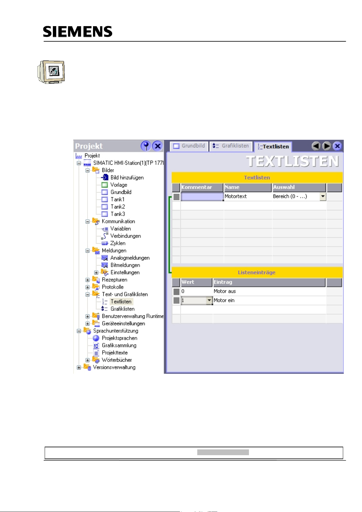
Automation and Drives - SCE
Generating a Text List
In the project window, double click on Text Lists in the folder “Text and Graphic Lists“.
In the column Name, double click on the first line, and create a new text list in this way.
Change the name of the text list to “Motor text“.
At Auswahl (selection), select “Range (0-…)“.
Below at Value 0, enter the text “Motor aus“ (motor off), and at Value 1 the text “Motor ein“ (motor
on).
Preface Installation Project Description Step7 Project HMI Station WinCC flexible Project Messages Recipes User Management
T I A Training Document Page 92 of 129 Module
F6
Issued: 02/2008 Operator Control with WinCC flexible 2005
Page 93

Automation and Drives - SCE
Inserting a Symbolic EA Field
Drag a Symbolic EA field into the basic display.
Set the mode to Eingabe/Ausgabe (input/output) and select the text list Motortext and the variable
“hand_mischermotor“. Adjust the font size, size and position.
Preface Installation Project Description Step7 Project HMI Station WinCC flexible Project Messages Recipes User Management
T I A Training Document Page 93 of 129 Module
F6
Issued: 02/2008 Operator Control with WinCC flexible 2005
Page 94

Automation and Drives - SCE
Under Animation at manual mode, activate the background color blue.
In addition, manual operation is to be possible only in the manual mode.
Test the function in runtime.
Preface Installation Project Description Step7 Project HMI Station WinCC flexible Project Messages Recipes User Management
T I A Training Document Page 94 of 129 Module
F6
Issued: 02/2008 Operator Control with WinCC flexible 2005
Page 95

Automation and Drives - SCE
8.3.3 Configuring the Manual Mode for the Outflow Valve of the Container
We are creating an additional button for opening the outflow valve.
From the tool window, under Basic Objects, drag a Button into the basic display.
Under Allgemein (General), at Text AUS, enter “Ablauf öffnen“ (open outflow). Set the check mark
for Text EIN, and enter the text “Ablauf offen“ (outflow open).
Caution! After entering the text, don’t press the enter key; otherwise, a new line is generated.
Change the background color to white, and select a smaller font size.
Set the position and the size.
In the function list, select the function “SetzeBit“ at Drücken (press).
From DB1, select as variable “hand_ablauf_behaelter“ (manual outflow container).
We want to generate the function of a button; for that reason, we are now configuring the function
“RuecksetzeBit“ (reset bit) with the variable “hand_ablauf_behaelter“ when releasing the button.
Preface Installation Project Description Step7 Project HMI Station WinCC flexible Project Messages Recipes User Management
T I A Training Document Page 95 of 129 Module
F6
Issued: 02/2008 Operator Control with WinCC flexible 2005
Page 96

Automation and Drives - SCE
The button is to be operable only in the manual mode.
Under Animationen, select Bedienbarkeit (operability) and place the checkmark at Activated.
As variable, select “H3_MAN“ from the symbols.
Enter 1 for “Von“ (from) and 1 for “Bis“ (to). Set the status to Activated.
The button can only be operated if the variable “H3_MAN“ has the value 1.
For operability to be visible, change the background color to blue at Style.
Test the function of the button in the manual and in the automatic mode.
Preface Installation Project Description Step7 Project HMI Station WinCC flexible Project Messages Recipes User Management
T I A Training Document Page 96 of 129 Module
F6
Issued: 02/2008 Operator Control with WinCC flexible 2005
Page 97

Automation and Drives - SCE
8.3.4 Switching the Operating Modes
Selecting the operating mode is also to be possible on the TP177B.
We are using a switch for this function.
Drag a switch into the basic display.
When making settings, select the switch with text, and enter the texts.
As variable, use “man_auto“ from DB1.
Preface Installation Project Description Step7 Project HMI Station WinCC flexible Project Messages Recipes User Management
T I A Training Document Page 97 of 129 Module
F6
Issued: 02/2008 Operator Control with WinCC flexible 2005
Page 98

Automation and Drives - SCE
Change the background color to blue, and select a smaller font size.
Set the position and the size.
At Style (Gestaltung), select the variable “H2_AUTO“ from the symbol table.
Test the manual/automatic switchover in runtime.
Preface Installation Project Description Step7 Project HMI Station WinCC flexible Project Messages Recipes User Management
T I A Training Document Page 98 of 129 Module
F6
Issued: 02/2008 Operator Control with WinCC flexible 2005
Page 99

Automation and Drives - SCE
8.3.5 Configuring the Fill Setpoints
The fill amounts for the tanks are to be entered by means of the TP177B.
To this end, input fields are configured.
Drag an EA field into the basic display.
Change the settings at General (Allgemein). Use the variable “ENTRY_T1“.
Preface Installation Project Description Step7 Project HMI Station WinCC flexible Project Messages Recipes User Management
T I A Training Document Page 99 of 129 Module
F6
Issued: 02/2008 Operator Control with WinCC flexible 2005
Page 100

Automation and Drives - SCE
Change the properties at Representation (Darstellung).
Change the properties at Text.
Copy and Insert the EA field. Position it each once next to Tank 2 on X171 and Tank 3 on X282.
Change the variables to VORGABE_T2 and VORGABE_T3.
Preface Installation Project Description Step7 Project HMI Station WinCC flexible Project Messages Recipes User Management
T I A Training Document Page 100 of 129 Module
F6
Issued: 02/2008 Operator Control with WinCC flexible 2005
 Loading...