

Siemens Uroskop D Troubleshooting manual
SIEMENS
UROSKOP D
Troubleshooting instructions
Register 5
RLL5-310.072.01.01.02
Replaces:
Weitergabe sowie VervielfSltigung dieser Unterlage. Verwertung und
Mitt&lung ihrer lnhaltr nicht gestattet. soweit ntcht ausdriicklich
zugestanden. Zuwderhandiungen verpfllchten zu Schadenersatz. Alle
Rechte vorbehalten, inrbemndere fijr den Fall der Patenterteilung oder
GM-Eintragung
Copyright (C) Siemens AG 1994
Proprietary data, company confidential All rlghtr reserved
Canfie a title de secret d’ entreprire Tous droits res&ves
Confiada corm secreto industrial Nos re~ewamos todos 105 derechar
English
06.96
o-2
Troubleshooting Instructions
Contents, Revision
0
1
2
3
Cover page
Contents/Revision
Board replacement on the UROSKOP D
Group error displays
Structure of the error displays
Error groups for console display on UROSKOP Dl,
UROSKOP D2 and UROSKOP D3 with SU
Error groups for console display on
UROSKOP Dl with LX and UROSKOP D2/D3 with SX
Basic unit system messages
Page
o-1/2
o-2
l-1/2
l-2
2-l/14
2-1
2-2
2-8
3-l/134
Rev.
01
01
01
01
01
4
System messages of the Uroskop Dl components 4-l/6
Polydoros LX - Videomed DI - XCS error listing
VIDEOMED DI TV system
POLYDOROS LX generator
4-l
4-l
4-2
01
Siemens AG
Medical Engineering
RLL5-310.072.01 .Oi .02
Rev. 01
Board replacement on the UROSKOP D 1-l
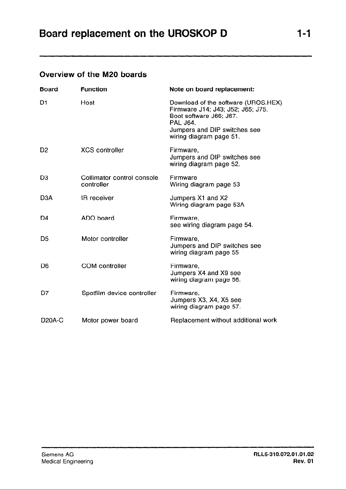
Overview of the M20 boards
Board Function
Dl Host
D2
D3
D3A
D4
D5
XCS controller
Collimator control console
controller
IR receiver
ADO board
Motor controller
Note on board replacement:
Download of the software (UROS.HEX)
Firmware J14; J43; J52; J65; J75.
Boot software J66; J67.
PAL J64.
Jumpers and DIP switches see
wiring diagram page 51.
Firmware,
Jumpers and DIP switches see
wiring diagram page 52.
Firmware
Wiring diagram page 53
Jumpers Xl and X2
Wiring diagram page 53A
Firmware,
see wiring diagram page 54.
Firmware,
Jumpers and DIP switches see
wiring diagram page 55
D6
D7
D20A-C Motor power board
COM controller
Spotfilm device controller
Firmware,
Jumpers X4 and X9 see
wiring diagram page 56.
Firmware,
Jumpers X3, X4, X5 see
wiring diagram page 57.
Replacement without additional work
Siemens AG
Medical Engineering
RLL5-310.072.01.01.02
Rev.
01
1-2 Board replacement on the UROSKOP D
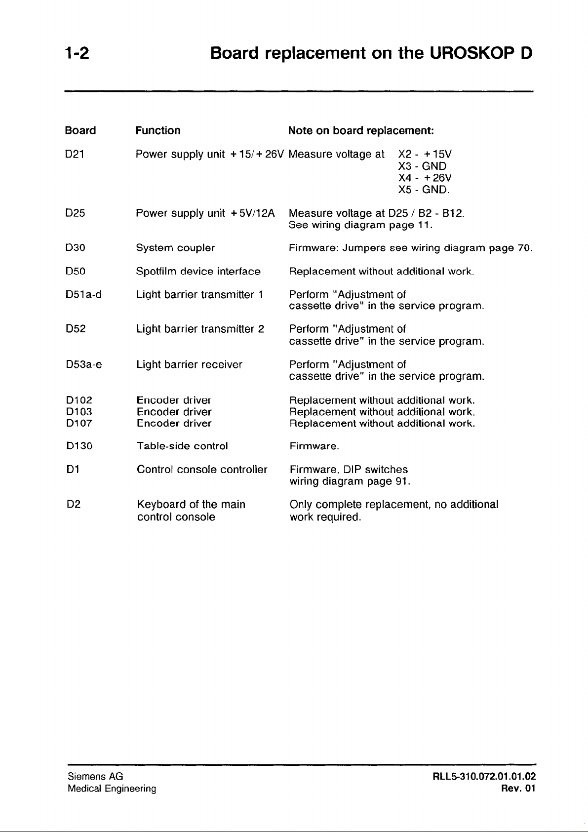
Board Function Note on board replacement:
D21 Power supply unit + 15/ + 26V Measure voltage at X2 - + 15V
X3
- GND
X4- +26V
X5
- GND.
D25 Power supply unit + 5V/12A
D30
D50
D51 a-d
D52 Light barrier transmitter 2
D53a-e Light barrier receiver Perform “Adjustment of
D102
D103
D107
D130
Dl
System coupler
Spotfilm device interface
Light barrier transmitter 1
Encoder driver
Encoder driver
Encoder driver
Table-side control
Control console controller
Measure voltage at D25 / B2 - B12.
See wiring diagram page 11.
Firmware: Jumpers see wiring diagram page 70.
Replacement without additional work.
Perform “Adjustment of
cassette drive” in the service program.
Perform “Adjustment of
cassette drive” in the service program.
cassette drive” in the service program.
Replacement without additional work.
Replacement without additional work.
Replacement without additional work.
Firmware.
Firmware, DIP switches
wiring diagram page 91.
D2
Siemens AG
Medical Engineering
Keyboard of the main
control console
Only complete replacement, no additional
work required.
RLL5-310.072.01 .01.02
Rev.
01

Group Error Listing 2-1
Structure of the error listing
The errors detected by the host are:
1.) displayed as flashing, 4-digit hex number on the host board Dl in the control rack
M20.
2.) displayed as 3-digit group display on the main control console in the area dose
indicator field visible for the customer (e.g. UOl).
With built-in Diamentor (UROSKOP D2/D3), an alternating display of dose and error
message is implemented.
Whereby
3.) entered in the short-time error memory of the UROSKOP, transferred into the longtime error memory after 1 minute or after shutting down the system.
The error entry contains the 4-digit hex number, initials of the component which has
reported the error, a single-line short description of the error, the date and the time.
e.g. Error number: # 50H Date: 21.04.93 Time: 06:34
or Error number: # B018H Date: 23.04.93 Time: 1507
Only the service engineer can delete the long-time error memory with the service PC.
(See UROSKOP D SSW description.)
U E
F
Emergency stop switch pressed
Spotfilm device: Direct exposure without free cassette
is a status message for the user.
- is an error, i.e. only part functions are disabled
(movement,
- is a fatal error, i.e. the system is disabled completely
(movement
or
radiation release
and
radiation release and communication)
or
communication)
Errors which cannot be processed by the customer service are identified with the remark
‘lint. SW Error”.
These errors generally have no influence on the operation of the system.
Siemens AG
Medical Engineering
RLL5-310.072.01 .01.02
Rev. 01
2-2
Group Error Listing
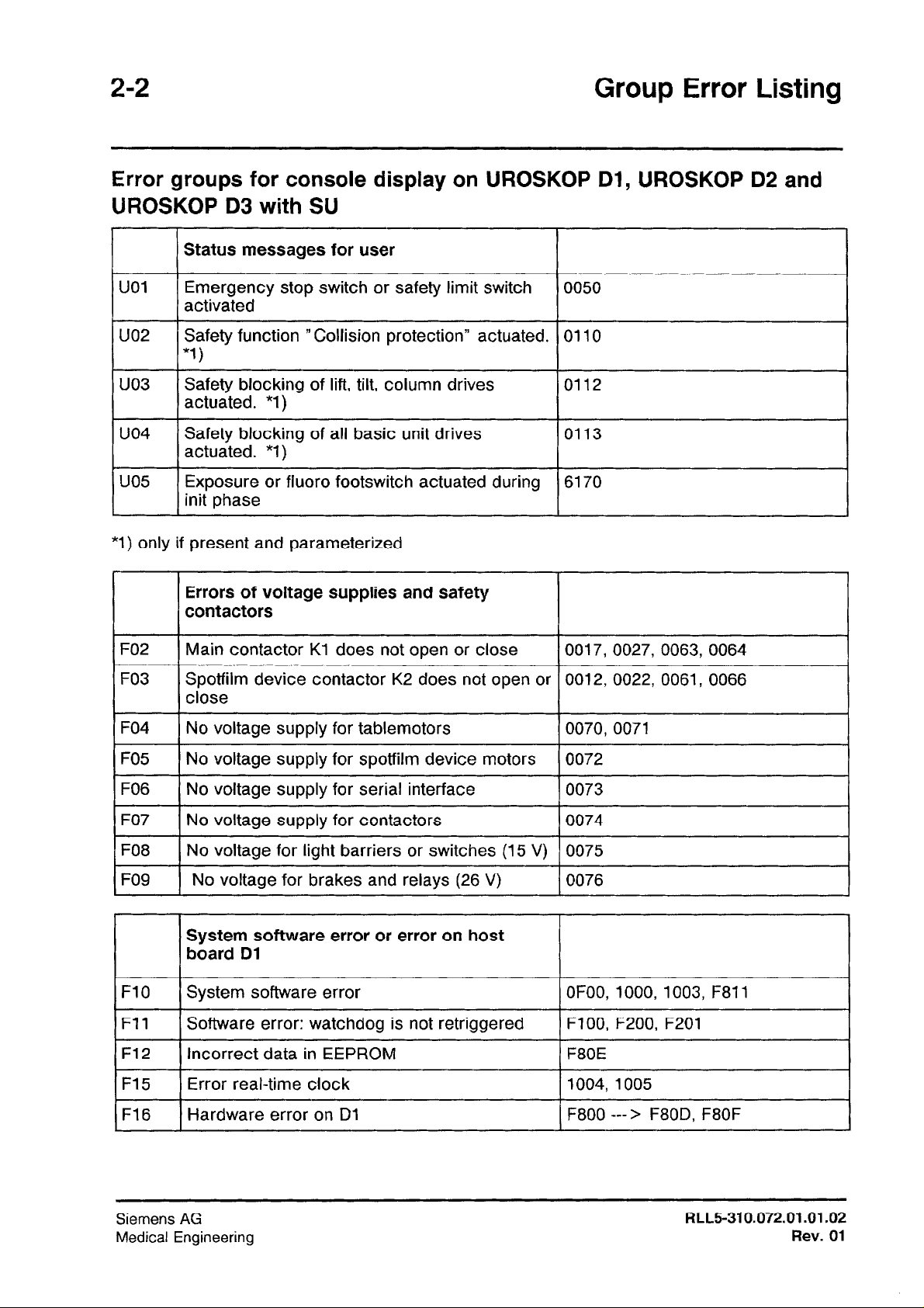
Error groups for console display on UROSKOP Dl, UROSKOP D2 and
UROSKOP D3 with SU
I
UOl
uo2
uo3
c
uo4
t-
uo5
t
*l) only if present and parameterized
I I
F02
I
F03
I I
Status
Emergency stop switch or safety limit switch
activated
Safety function ‘Collision protection” actuated. 0110
*1i
Safety blocking of lift, tilt, column drives
actuated. “1)
Safety blocking of all basic unit drives
actuated. *l)
Exposure or fluoro footswitch actuated during 6170
init phase
Errors of voltage supplies and safety
contactors
1 Main contactor Kl does not open or close 10017, 0027, 0063, 0064
Spotfilm device contactor K2 does not open or 0012, 0022, 0061, 0066
close
messages for user
I I
0050
0112
0113
I
F04
1
F05
FO6
F07
FO8 1 No voltage for light barriers or switches (15 V) ) 0075
I
FO9 No voltage for brakes and relays (26 V) 0076
FlO 1 System software error
I
Fll
I
F12
I
F15
I
F16
I
No voltage supply for tablemotors
No voltage supply for spotfilm device motors 0072
No voltage supply for serial interface
No voltage supply for contactors
System software error or error on host
board Dl
Software error: watchdog is not retriggered
I
Incorrect data in EEPROM
I
Error real-time clock
Hardware error on Dl
0070,0071
1
0073
0074
OFOO, 1000,1003, F811
I
FlOO, F200, F201
I
F800 ---> F80D, F8OF
I
I
I
I
I
I
Siemens AG
Medical Engineering
RLL5-310.072.01 .01.02
Rev. 01
Group Error Listing 2-3
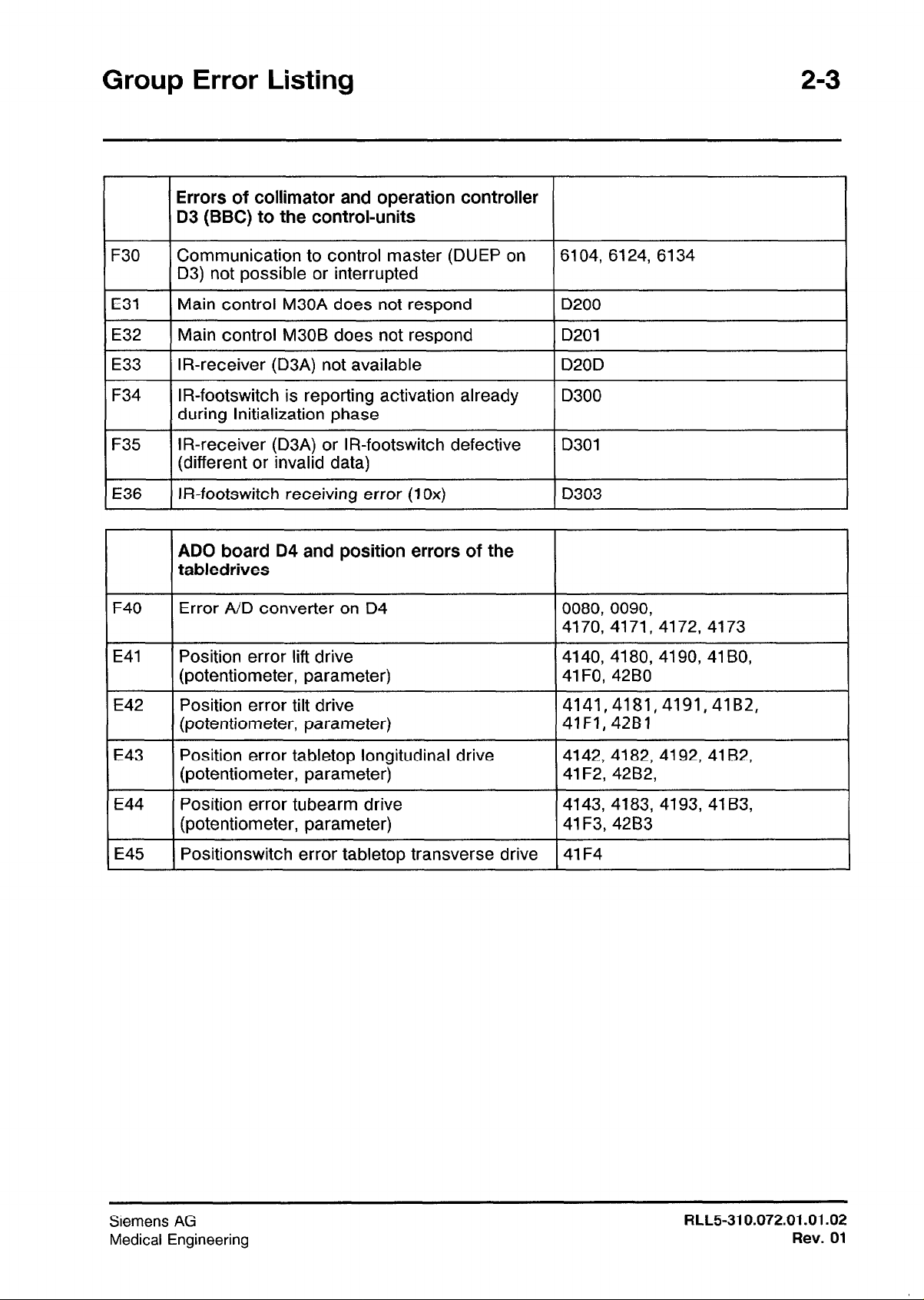
Errors of collimator and operation controller
D3 (BBC) to the control-units
F30
E31
E32
I
E33
F34
F35
E36
I I I
F40
E41
I I
E42
I I
E43
I I
E44
I I
Communication to control master (DUEP on
D3) not possible or interrupted
Main control M30A does not respond
Main control M30B does not respond
IR-receiver (D3A) not available
IR-footswitch is reporting activation already
during lnitialization phase
IR-receiver (D3A) or IR-footswitch defective
(different or invalid data)
IR-footswitch receiving error (1 Ox)
ADO board D4 and position errors of the
tabledrives
Error ND converter on D4
Position error lift drive 4140, 4180, 4190, 41 BO,
(potentiometer, parameter) 41F0, 42B0
Position error tilt drive 4141,4181,4191,41B2,
(potentiometer, parameter) 41F1,42Bl
Position error tabletop longitudinal drive 4142, 4182, 4192, 41 B2,
(potentiometer, parameter)
Position error tubearm drive 4143, 4183, 4193, 4163,
(potentiometer, parameter)
6104, 6124, 6134
D200
D201
I
D20D
D300
D301
D303
0080, 0090,
4170, 4171, 4172, 4173
41 F2, 42B2,
41 F3,4283
E45
I
Siemens AG
Medical Engineering
I Positionswitch error tabletop transverse drive I 41 F4
RLL5-310.072.01.01.02
Rev. 01
2-4
Group Error Listing
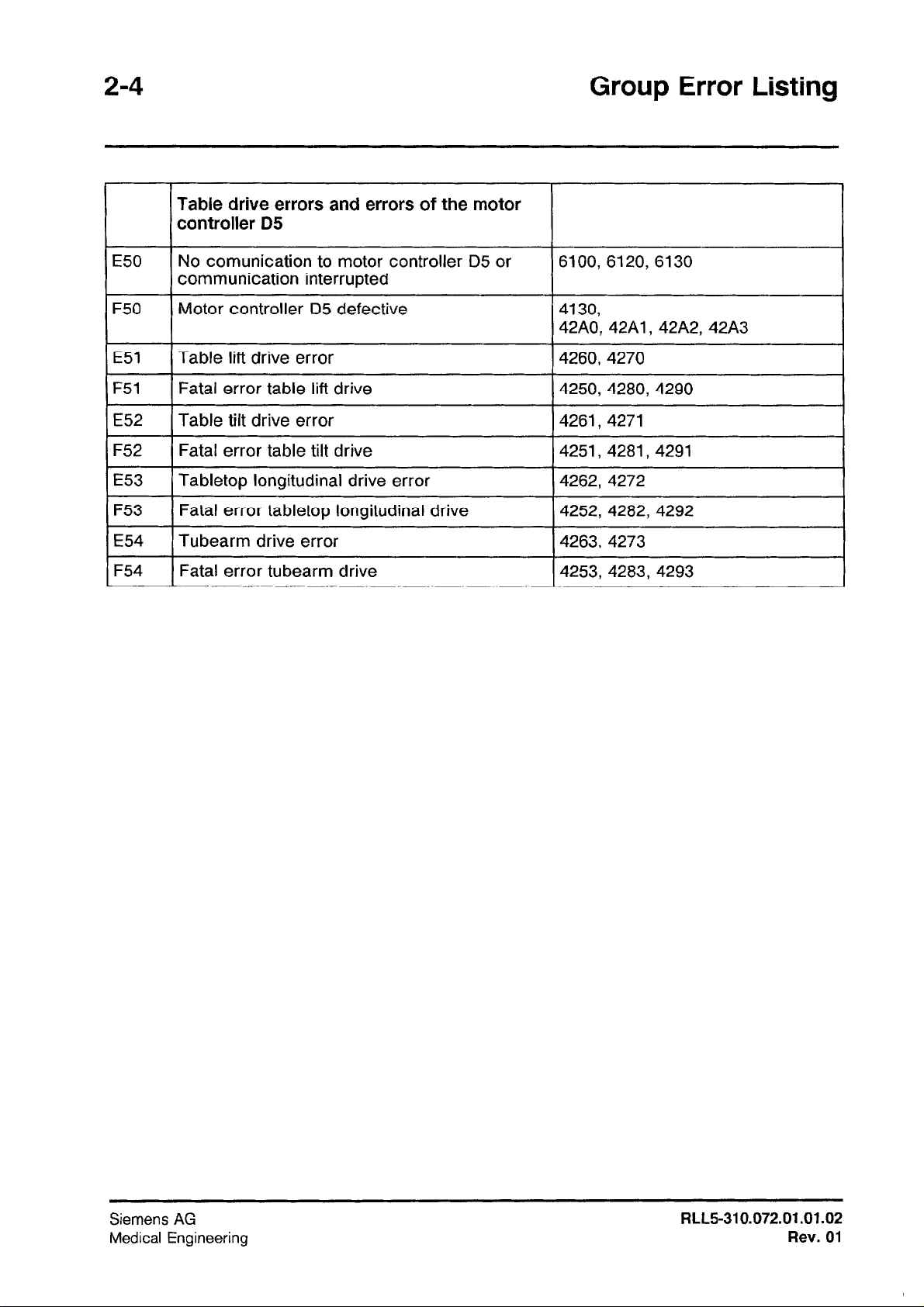
Table drive errors and errors of the motor
controller D5
E50
F50
E51
F51
E52
F52
E53
F53
E54
F54
No comunication to motor controller 05 or
communication interrupted
Motor controller D5 defective
Table lift drive error
Fatal error table lift drive
Table tilt drive error
Fatal error table tilt drive
Tabletop longitudinal drive error
Fatal error tabletop longitudinal drive
Tubearm drive error
Fatal error tubearm drive
6100, 6120, 6130
4250,4280,4290
4261, 4271
4251, 4281,429l
4262, 4272
4252, 4282, 4292
,4263, 4273
4253, 4283, 4293
I
Siemens AG
Medical Engineering
FtLL5-310.072.01 .01.02
Rev.
01
Group Error Listing
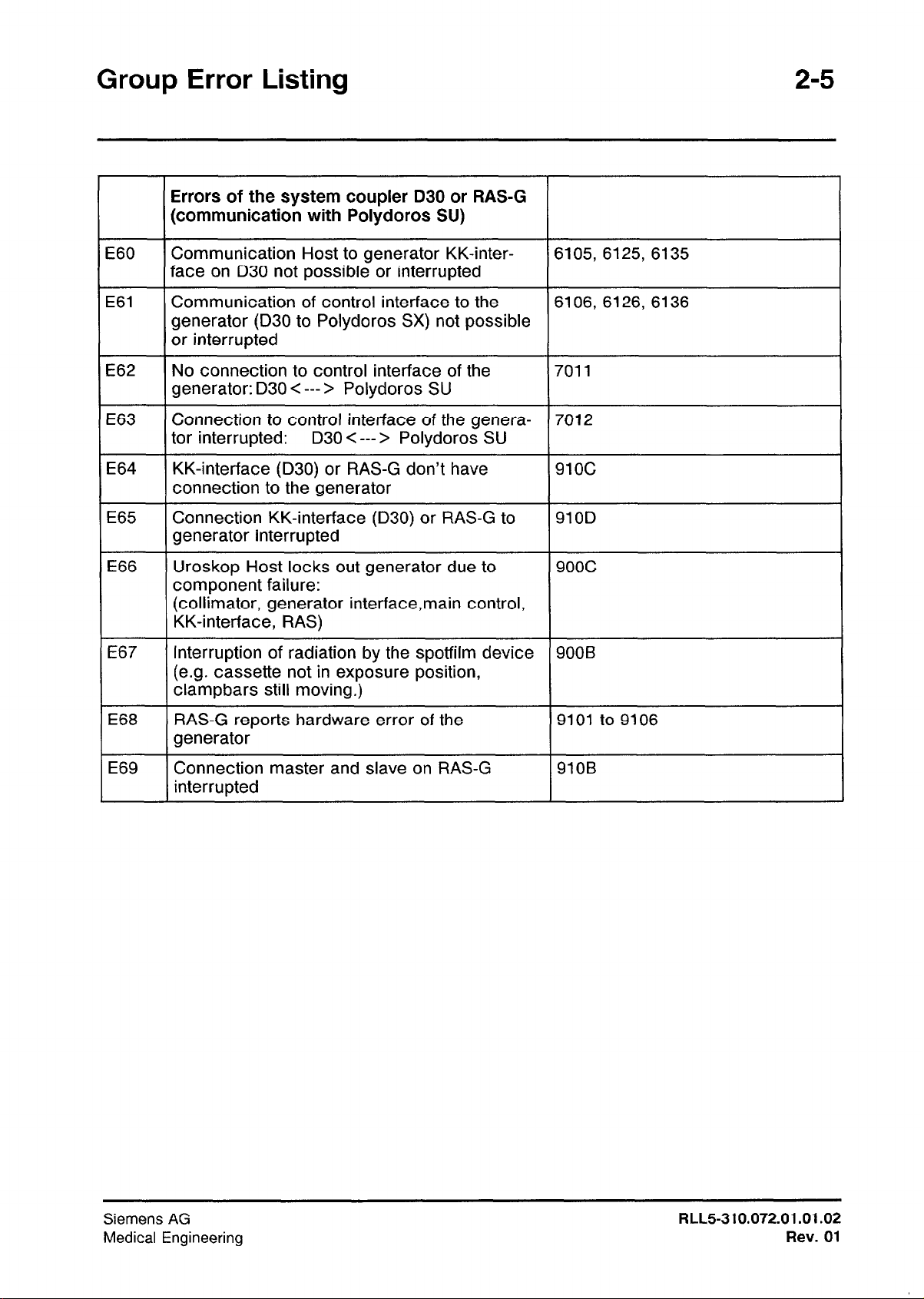
Errors of the system coupler D30 or RAS-G
(communication with Polydoros SU)
2-5
E60
E61
E62
E63
E64
E65
E66
E67
Communication Host to generator KK-interface on D30 not possible or interrupted
Communication of control interface to the
generator (D30 to Polydoros SX) not possible
or interrupted
No connection to control interface of the
generator: D30 < --- > Polydoros SU
Connection to control interface of the genera-
tor interrupted:
KK-interface (D30) or RAS-G don’t have
connection to the generator
Connection KK-interface (D30) or RAS-G to
generator interrupted
Uroskop Host locks out generator due to
component failure:
(collimator, generator interface,main control,
KK-interface, RAS)
Interruption of radiation by the spotfilm device
(e.g. cassette not in exposure position,
clampbars still moving.)
D30 < --- > Polydoros SU
6105, 6125, 6135
6106, 6126, 6136
7011
7012
91oc
910D
9ooc
900B
E68
E69
RAS-G reports hardware error of the
generator
Connection master and slave on RAS-G
interrupted
9101
910B
to 9106
Siemens AG
Medical Engineering
FILL5310.072.01.01.02
Rev.
01
2-6
Group Error Listing
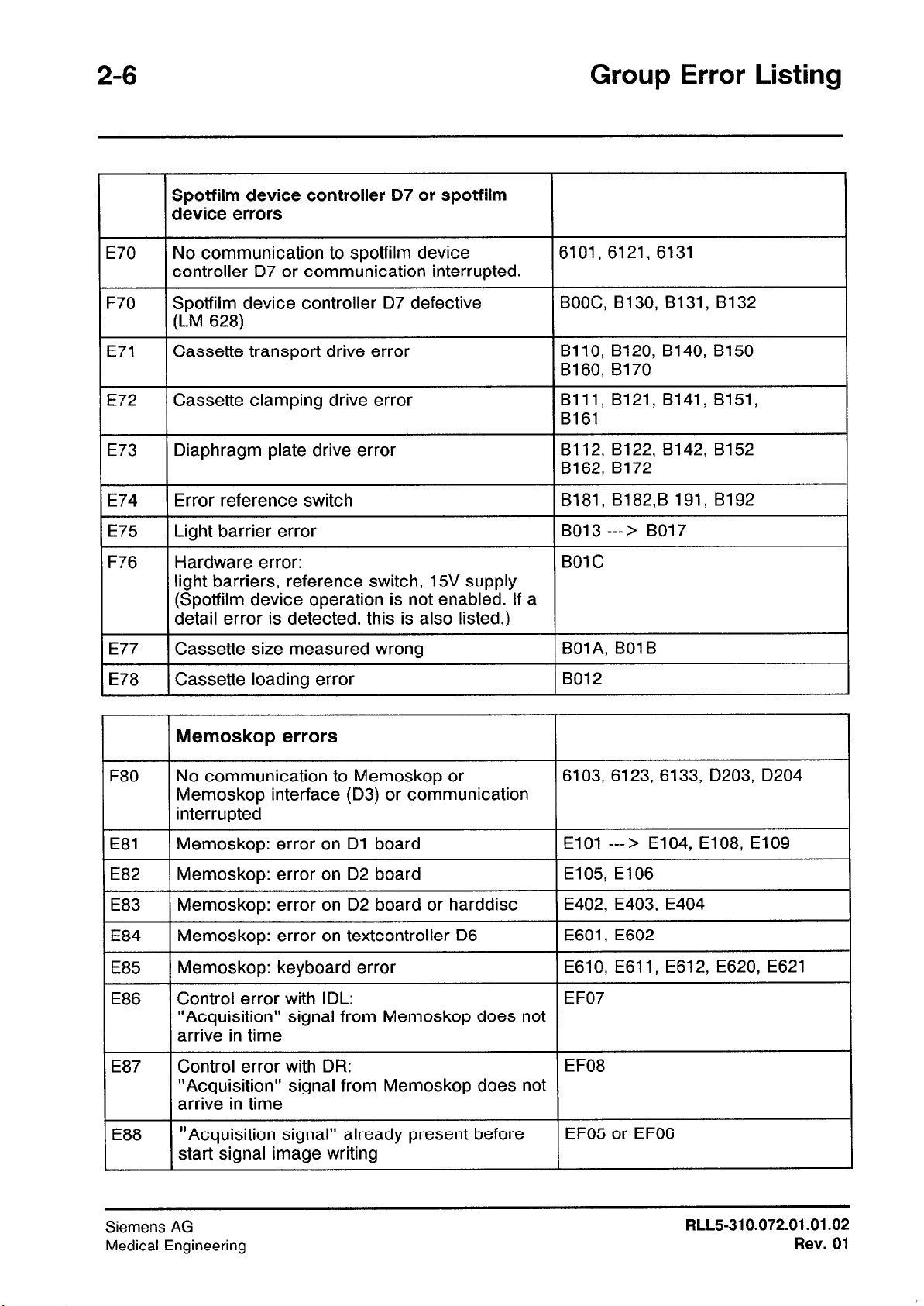
Spotfilm device controller D7 or spotfilm
device errors
E70
F70 Spotfilm device controller D7 defective BOOC, B130, 8131, B132
E71 Cassette transport drive error BllO, B120, B140, B150
E72 Cassette clamping drive error
E73
E74 Error reference switch 8181, B182,B 191, B192
E75
F76
E77
E78
No communication to spotfilm device 6101, 6121, 6131
controller D7 or communication interrupted.
(LM 628)
B160, B170
Bill, B121, B141, B151,
B161
Diaphragm plate drive error B112, B122, B142, B152
B162, B172
Light barrier error B013 ---> B017
Hardware error:
light barriers, reference switch, 15V supply
(Spotfilm device operation is not enabled. If a
detail error is detected, this is also listed.)
Cassette size measured wrong
Cassette loading error B012
BOlC
BOl A, BOl B
Memoskop errors
F80 No communication to Memoskop or
Memoskop interface (D3) or communication
interrupted
E81
E82
E83
E84
E85
E86
E87
E88
Memoskop: error on Dl board
Memoskop: error on D2 board E105, El06
Memoskop: error on D2 board or harddisc E402, E403, E404
Memoskop: error on textcontroller D6 E601, E602
Memoskop: keyboard error
Control error with IDL:
“Acquisition” signal from Memoskop does not
arrive in time
Control error with DR: EF08
“Acquisition” signal from Memoskop does not
arrive in time
“Acquisition signal” already present before
start signal image writing
6103, 6123, 6133, D203, D204
El01 ---> E104, E108, El09
E610, E611, E612, E620, E621
EF07
EF05 or EF06
Siemens AG
Medical Engineering
RLL5-310.072.01 .01.02
Rev. 01
Group Error Listing
2-7
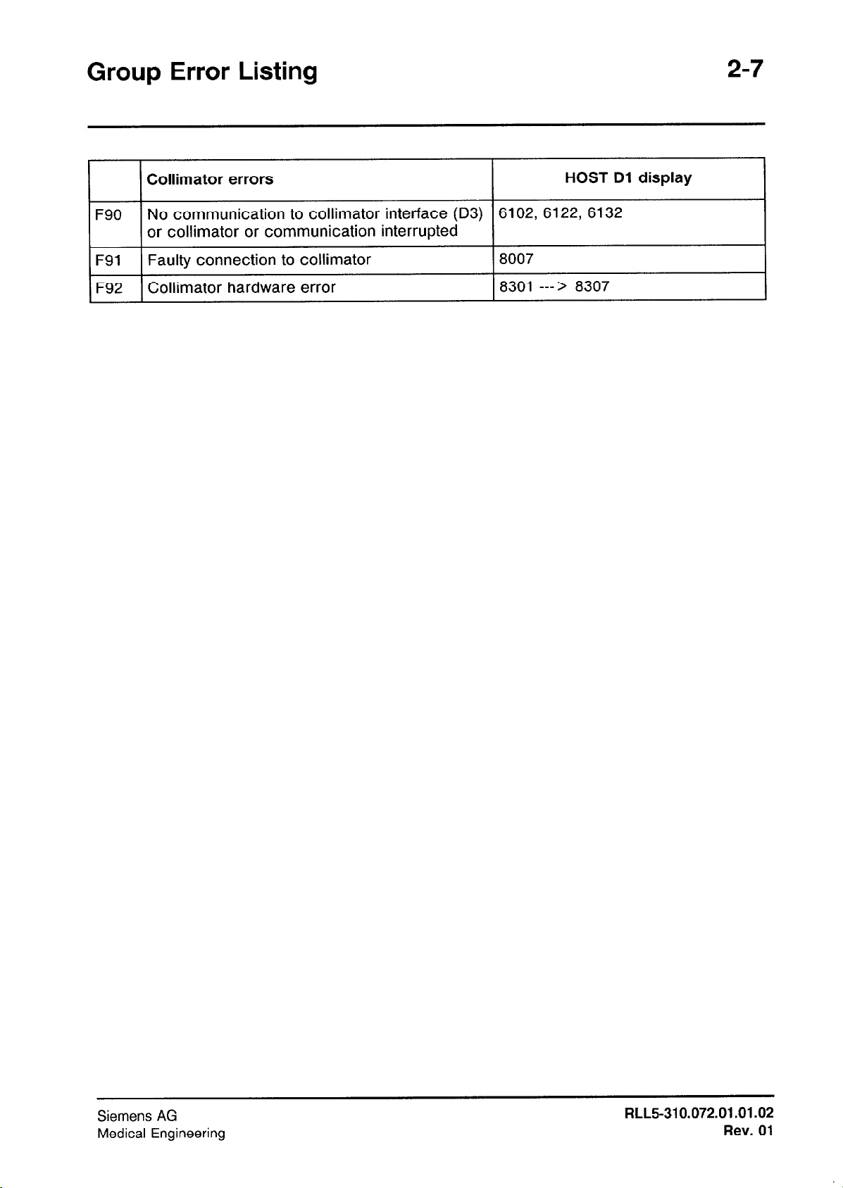
Collimator errors
I
F90 No communication to collimator interface (D3)
or collimator or communication interrupted
F91 Faulty connection to collimator
F92 Collimator hardware error
HOST Dl display
6102, 6122, 6132
8007
8301 ---> 8307
Siemens AG
Medical Engineering
RLL5-310.072.01 .01.02
Rev. 01
2-8
Group Error Listing
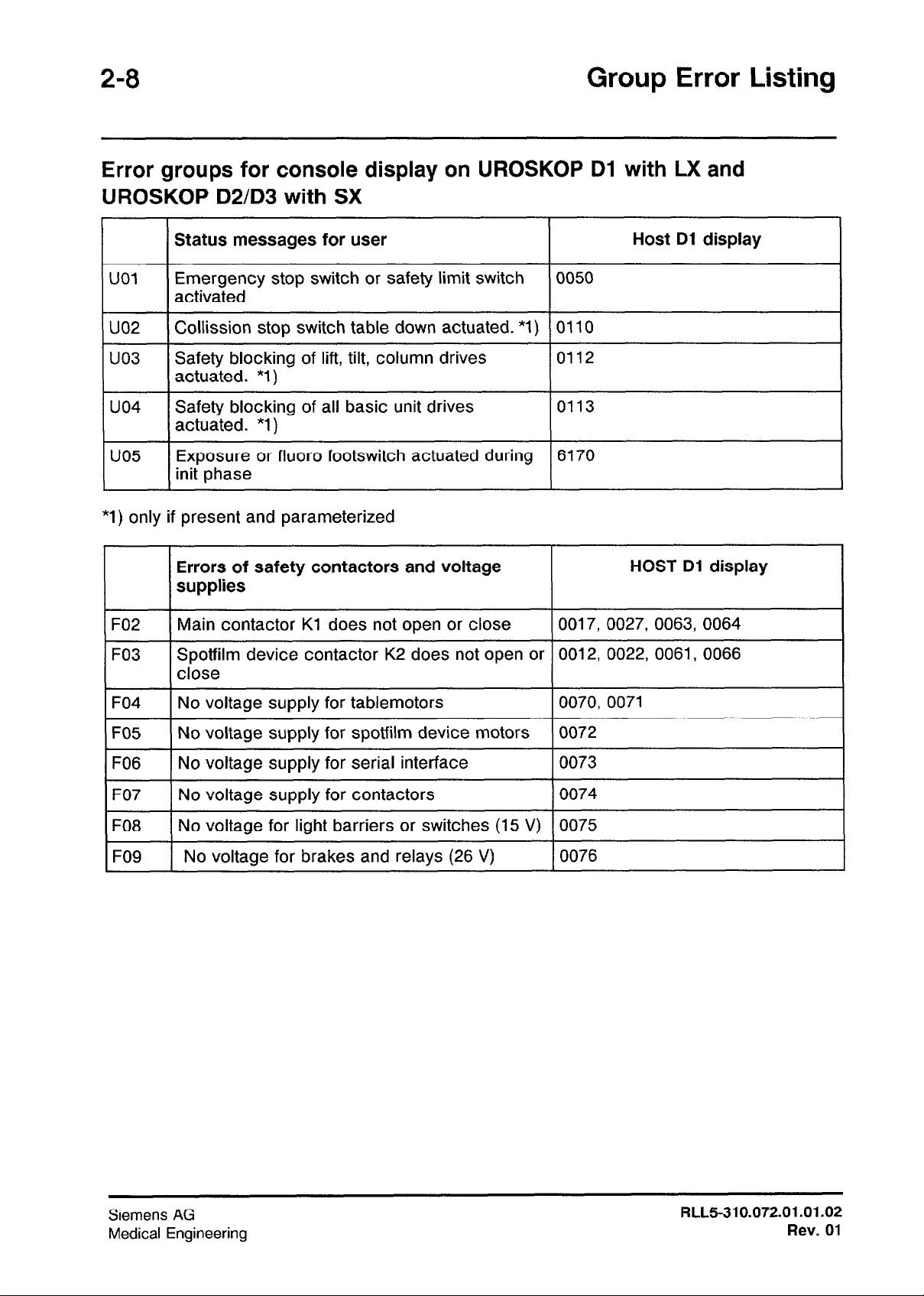
Error groups for console display on UROSKOP Dl with LX and UROSKOP D2/D3 with SX
Status messages for user Host Dl display
UOI
uo2
uo3
uo4
uo5
*l) only if present and parameterized
Emergency stop switch or safety limit switch
activated
Collission stop switch table down actuated. *l)
Safety blocking of lift, tilt, column drives 0112
actuated. *1 )
Safety blocking of all basic unit drives 0113
actuated. *l)
Exposure or fluoro footswitch actuated during 6170
init phase
Errors of safety contactors and voltage
supplies
F02
F03
F04
Main contactor Kl does not open or close
Spotfilm device contactor K2 does not open or 0012, 0022, 0061, 0066
close
No voltage supply for tablemotors
0050
0110
HOST Dl display
0017, 0027, 0063, 0064
0070, 0071
F05
FO6
F07
FO8
FO9
No voltage supply for spotfilm device motors 0072
No voltage supply for serial interface 0073
No voltage supply for contactors 0074
No voltage for light barriers or switches (15 V)
No voltage for brakes and relays (26 V) 0076
0075
Siemens
Medical Engineering
AG
RLL5-310.072.01.01.02
Rev. 01
Group Error Listing
2-9
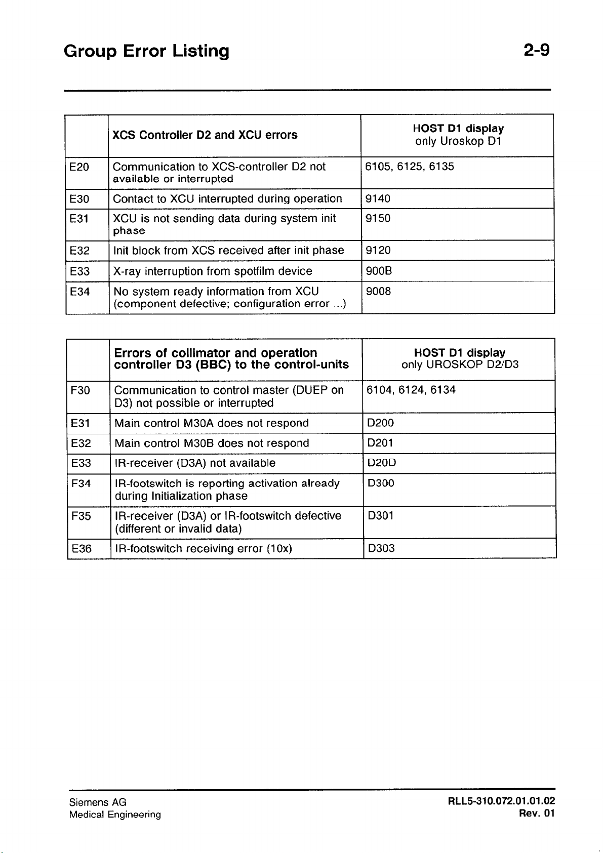
XCS Controller D2 and XCU errors
E20
I I
E30 1 Contact to XCU interrupted during operation
I
E31
I I
E32
I
1 E33
F30
I I
Communication to XCS-controller D2 not
available or interrupted
XCU is not sending data during system init
phase
lnit block from XCS received after init phase
I
X-ray interruption from spotfilm device
I
No system ready information from XCU
(component defective; configuration error . ..)
Errors of collimator and operation
controller D3 (BBC) to the control-units
Communication to control master (DUEP on
D3) not possible or interrupted
HOST Dl display
only Uroskop Dl
6105, 6125, 6135
I9140
9150
9120
I
9008
HOST Dl display
only UROSKOP D2/D3
6104, 6124, 6134
I
E31
E32
E33
F34
I I
F35
E36
Main control M30A does not respond
Main control M30B does not respond
IR-receiver (D3A) not available
IR-footswitch is reporting activation already
during lnitialization phase
IR-receiver (D3A) or IR-footswitch defective
(different or invalid data)
IR-footswitch receiving error (1 Ox)
D200
D201
D20D
D300
D301
D303
Siemens AG
Medical Engineering
RLL5-310.072.01.01.02
Rev. 01
2-10 Group Error Listing
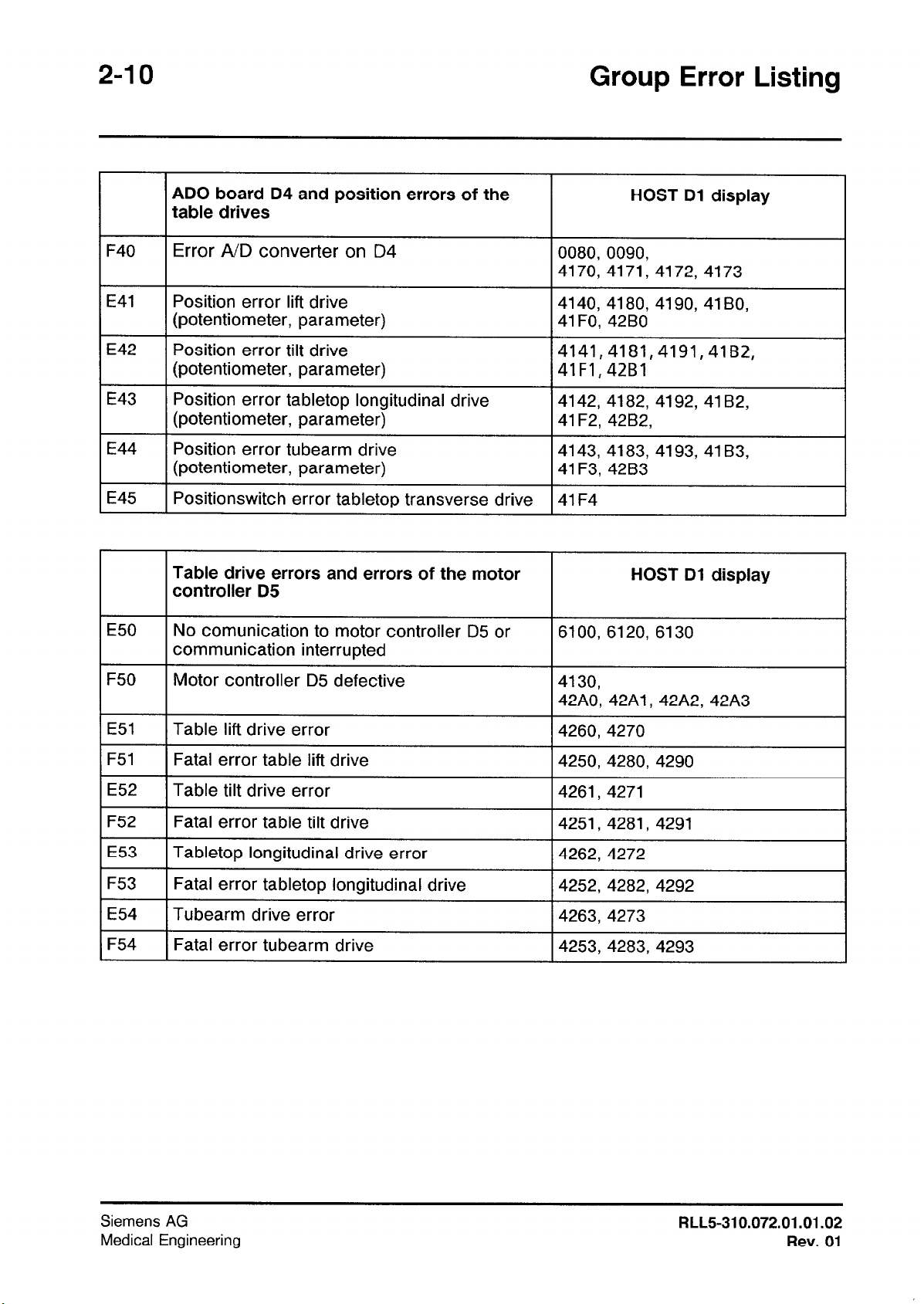
ADO board D4 and position errors of the
table drives
F40
E41
E42
E43
E44
E45 1 Positionswitch error tabletop transverse drive
Error A/D converter on D4
Position error lift drive 4140, 4180, 4190, 41 BO,
(potentiometer, parameter)
Position error tilt drive
(potentiometer, parameter)
Position error tabletop longitudinal drive
(potentiometer, parameter)
Position error tubearm drive
(potentiometer, parameter)
Table drive errors and errors of the motor
controller D5
E50
No comunication to motor controller D5 or
communication interrupted
HOST Dl display
0080, 0090,
4170, 4171, 4172, 4173
41F0, 42B0
4141,4181,4191,41B2,
41Fl,42Bl
4142, 4182, 4192, 41 B2,
41 F2, 42B2,
4143, 4183, 4193, 41 B3,
41 F3, 42B3
I41 F4
HOST Dl display
6100, 6120, 6130
I
F50
E51
F51
E52
F52
E53
F53
E54
F54
Motor controller D5 defective
Table lift drive error
Fatal error table lift drive
Table tilt drive error
Fatal error table tilt drive
Tabletop longitudinal drive error
Fatal error tabletop longitudinal drive
Tubearm drive error
Fatal error tubearm drive
4130,
42A0, 42A1, 42A2, 42A3
4260, 4270
4250,4280, 4290
4261, 4271
4251, 4281, 4291
4262,4272
4252, 4282, 4292
4263, 4273
4253,4283,4293
Siemens AG
Medical Engineering
RLL5-310.072.01 .01.02
Rev. 01
Group Error Listing
2-11
E60
E61
E62
E63
E64
E65
E66
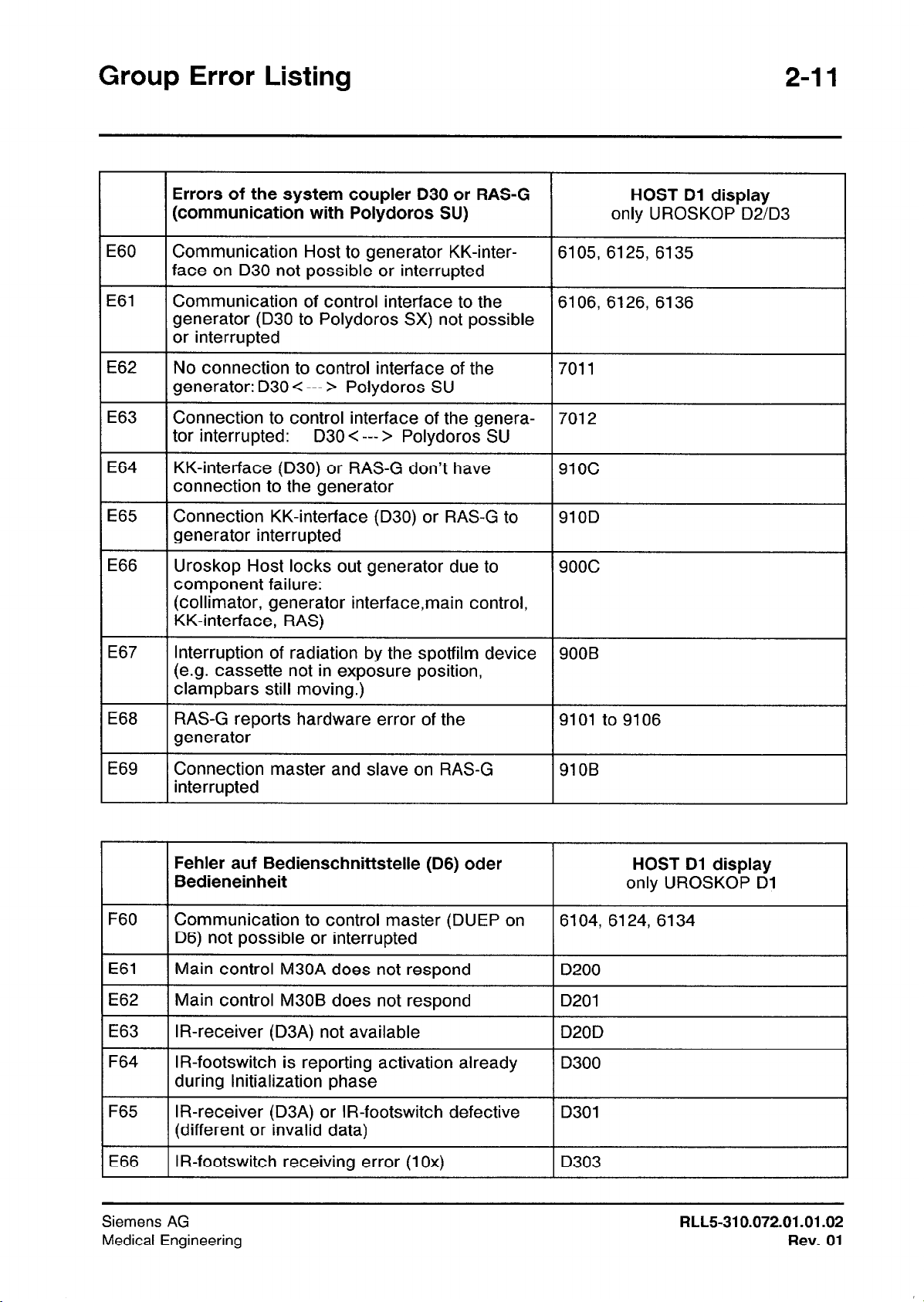
Errors of the system coupler D30 or RAS-G
(communication with Polydoros SU)
Communication Host to generator KK-inter-
face on D30 not possible or interrupted
Communication of control interface to the
generator (D30 to Polydoros SX) not possible
or interrupted
No connection to control interface of the
generator: D30 < --- > Polydoros SU
Connection to control interface of the genera-
tor interrupted:
KK-interface (D30) or RAS-G don’t have
connection to the generator
Connection KK-interface (D30) or RAS-G to
generator interrupted
Uroskop Host locks out generator due to
component failure:
(collimator, generator interface,main control,
KK-interface, RAS)
D30 < --- > Polydoros SU
HOST Dl display
only UROSKOP D2/D3
6105, 6125, 6135
6106, 6126, 6136
7011
7012
91oc
910D
9ooc
E67
E68
E69
F60
E61
E62
E63
F64
Interruption of radiation by the spotfilm device
(e.g. cassette not in exposure position,
clampbars still moving.)
RAS-G reports hardware error of the
generator
Connection master and slave on RAS-G
interrupted
Fehler auf Bedienschnittstelle (D6) oder
Bedieneinheit
Communication to control master (DUEP on
D6) not possible or interrupted
Main control M30A does not respond
Main control M30B does not respond
IR-receiver (D3A) not available
IR-footswitch is reporting activation already
during lnitialization phase
900B
9101 to 9106
910B
HOST Dl display
only UROSKOP Dl
6104, 6124, 6134
D200
D201
D20D
D300
F65
E66
Siemens AG
Medical Engineering
IR-receiver (D3A) or IR-footswitch defective
(different or invalid data)
IR-footswitch receiving error (1 Ox)
D301
D303
RLL5-310.072.01 .01.02
Rev. 01
2-12
Group Error Listing
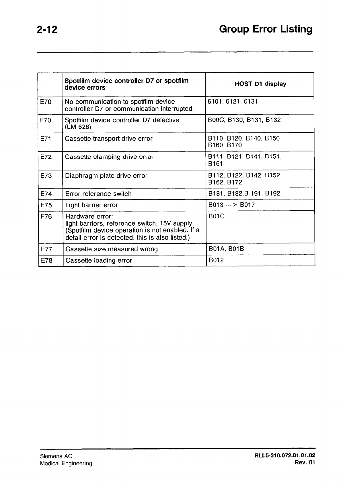
Spotfilm device controller D7 or spotfilm
device errors
E70
F70
E71
E72 Cassette clamping drive error
E73
E74 Error reference switch
E75
F76
No communication to spotfilm device 6101, 6121, 6131
controller D7 or communication interrupted.
Spotfilm device controller D7 defective BOOC, B130, Bl31, B132
(LM 628)
Cassette transport drive error
Diaphragm plate drive error
Light barrier error
Hardware error:
light barriers, reference switch, 15V supply
(Spotfilm device operation is not enabled. If a
detail error is detected, this is also listed.)
HOST Dl display
BIIO, B120, B140, B150
Bl60, B170
Blll, Bl21, Bl41, B151,
8161
8112, B122, B142, B152
B162, B172
Bl81, Bl82,B 191, B192
B013 ---> B017
BOI C
E77 Cassette size measured wrong
E78
Cassette loading error
BOlA, BOlB
B012
Siemens AG
Medical Engineering
RLL5-310.072.01 .01.02
Rev. 01
Group Error Listing
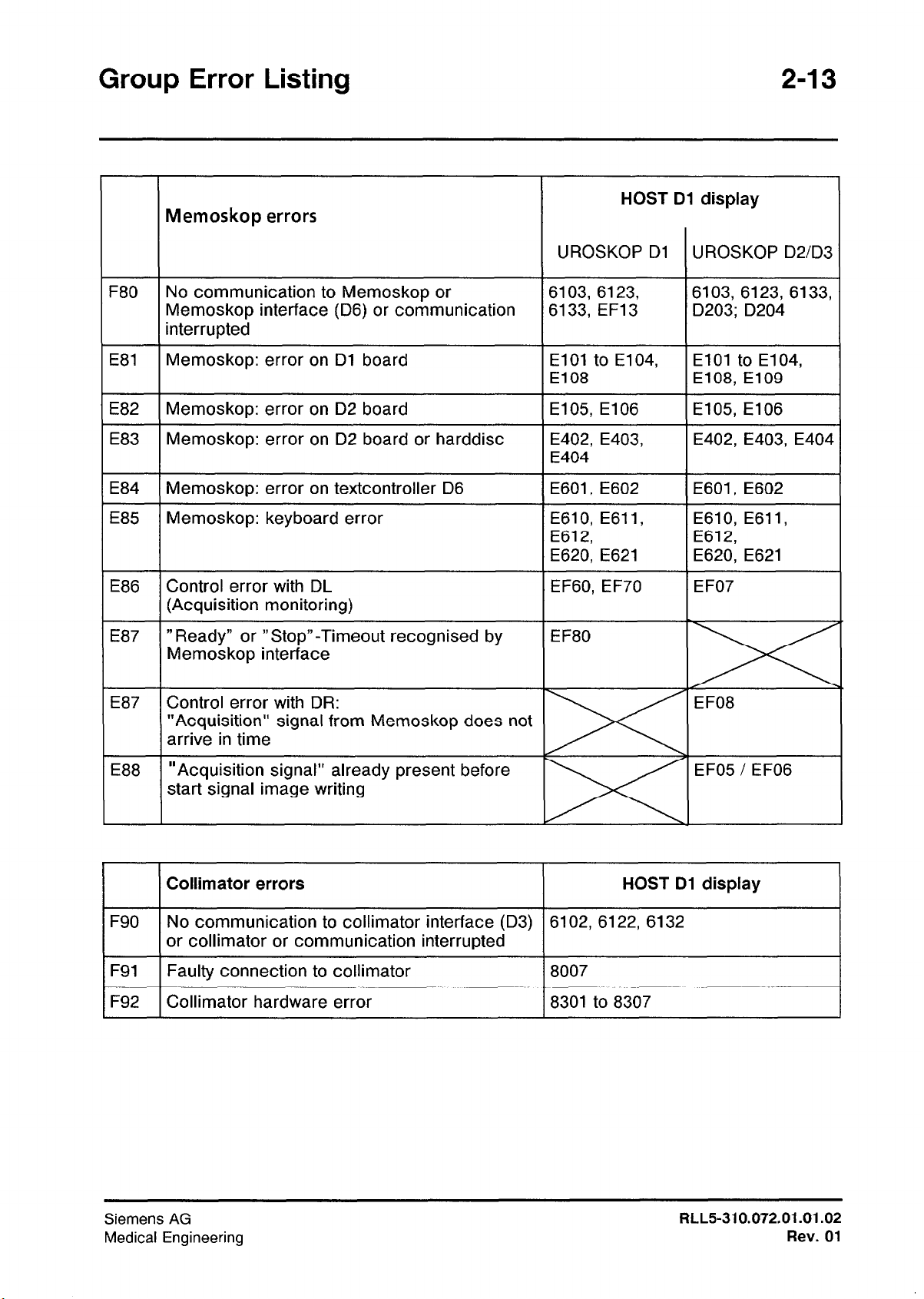
Memoskop errors
HOST Dl display
UROSKOP Dl UROSKOP D2/D3
F80
E81
E82
E83
E84
E85
E86
E87
E87
No communication to Memoskop or
Memoskop interface (D6) or communication
interrupted
Memoskop: error on Dl board
Memoskop: error on D2 board
Memoskop: error on D2 board or harddisc
Memoskop: error on textcontroller D6
Memoskop: keyboard error
Control error with DL
(Acquisition monitoring)
” Ready” or ” Stop”-Timeout recognised by
Memoskop interface
“Acquisition” signal from Memoskop does not
arrive in time
6103, 6123,
6133, EF13
El01 to E104,
El08
E105, El06
E402, E403,
E404
E601, E602 E601, E602
E610, E61 I,
E612,
E620, E621
EF60, EF70
EF80
6103, 6123, 6133,
D203; D204
El01 to E104,
E108, El09
El05,El06
E402,E403, E404
E610, E611,
E612,
E620, E621
EF07
EF08 Control error with DR:
E88
F90
I I
1 F91 1 Faulty connection to collimator
1 F92 1 Collimator hardware error
“Acquisition signal” already present before
start signal image writing
Collimator errors HOST Dl display
I
No communication to collimator interface (D3)
or collimator or communication interrupted
6102,6122,6132
18007
18301 to 8307
EF05 / EF06
m
I
Siemens AG
Medical Engineering
RLL5-310.072.01.01.02
Rev. 01

2-14
Group Error Listing
This page has been left blank intentionally.
Siemens AG
Medical Engineering Rev.
RLL5-310.072.01.01.02
01
Basic Unit System Messages
Terms used
Host display:
The four-digit error display on the board Dl in the M20Nroskop.
Only after removal of the cabinet cover.
Error group:
The three-digit group error display on the main control console in the area dose
product display is visible for the customer.
Description:
Text as entered in the long-term error memory (only English).
Test:
Suggestions for error localization and troubleshooting.
Choose the sequence of tests according to the prevailing situation.
3-1
Remedy:
Proposals for error rectification.
Choose the sequence of the measures to be performed for error rectification,
replacement of components or parts according to the prevailing situation.
Abbreviations used:
BM
ZG
TB
KK
PD
DUEP
MC
IMG
BS
BED
Operating mode
Spotfilm device
Collimator
KK interface
Polydoros
Data transmission program
Motor controller
Imaging system (viewed from the memory)
Image storage (viewed from the Uroskop)
Operating master (
= DUEP for all serial connections)
Designation of the slaves:
Slave 0
Slave
Slave 2
Slave 3
Slave 4
Slave
Slave
Slave C
Slave D
Main control unit 1
Main control unit 2
1
not used
CPU 1 image storage
CPU 2 image storage
A
not used
Table-side control unit 1
B
Table-side control unit 2
IR foot switch
Siemens
Medical Engineering
AG
RLL5-310.072.01.01.02
Rev.
01
3-2 Basic Unit System Messages
Communication of the basic unit with the generator.
Display
Additional message from the generator
Display
80 in the mAs display of the main control unit.
During the initialization phase of the system
if the generator is not yet finally initialized.
If the basic unit is shut down with the power switch SIOO in the M20 and is switched
on again.
If a reset has been performed on the host board Dl.
A reset of the generator is initiated by briefly pressing the precontact of the exposure
release switch.
88 in the mAs display of the main control unit.
Each time the system is switched on during the initialization phase.
Fluorospot H error codes
see Camtronics service instructions.
ERR 185 or ERRlOl,
Siemens AG
Medical Engineering
RLL5-310.072.01 .01.02
Rev. 01
Basic Unit System Messages
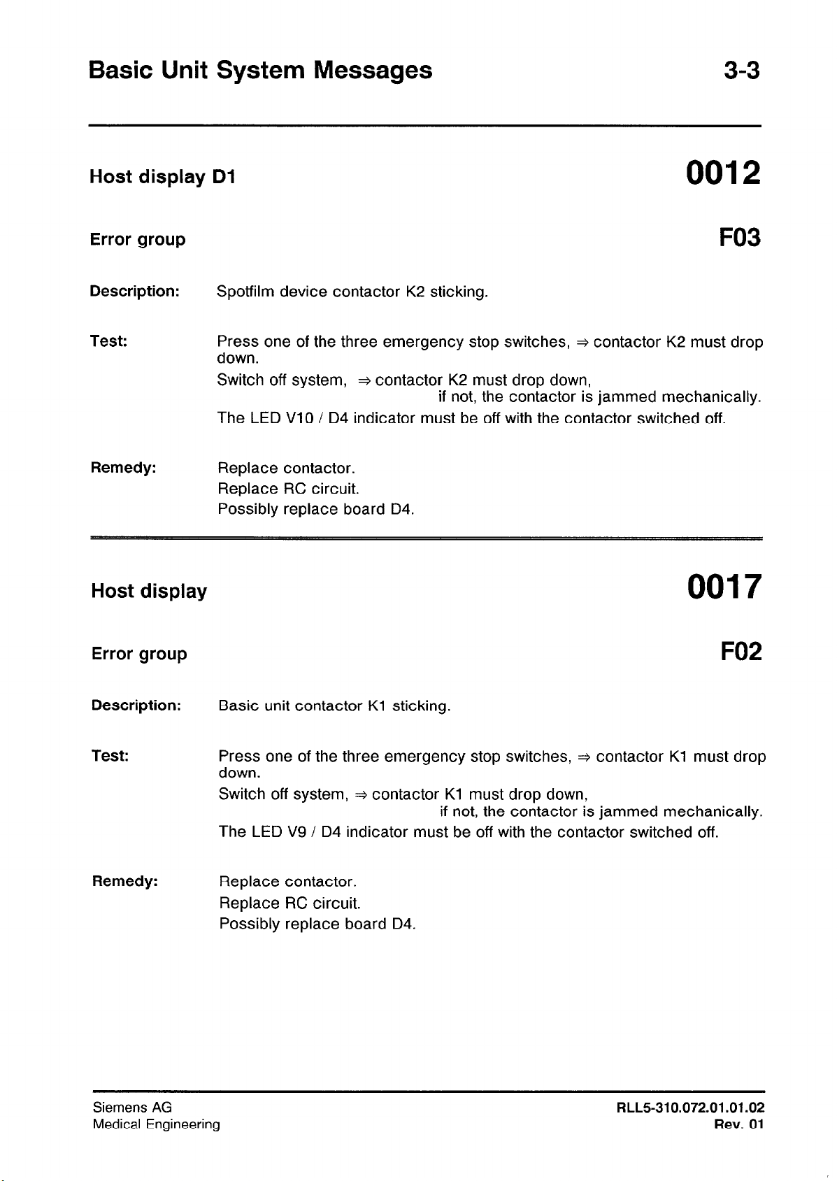
Host display Dl
Error group
Description:
Test:
Remedy:
Host display
F03
Spotfilm device contactor K2 sticking.
Press one of the three emergency stop switches, + contactor K2 must drop
down.
Switch off system, + contactor K2 must drop down,
if not, the contactor is jammed mechanically.
The LED VlO / D4 indicator must be off with the contactor switched off.
Replace contactor.
Replace RC circuit.
Possibly replace board D4.
0017
Error group
Description:
Test:
Remedy:
F02
Basic unit contactor Kl sticking.
Press one of the three emergency stop switches, + contactor Kl must drop
down.
Switch off system, 3 contactor Kl must drop down,
if not, the contactor is jammed mechanically.
The LED V9 / D4 indicator must be off with the contactor switched off.
Replace contactor.
Replace RC circuit.
Possibly replace board D4.
Siemens AG
Medical Engineering
RLL5-310.072.01.01.02
Rev. 01
Host display
Error group
Basic Unit System Messages
Description:
Test:
Remedy:
Host display
Error group
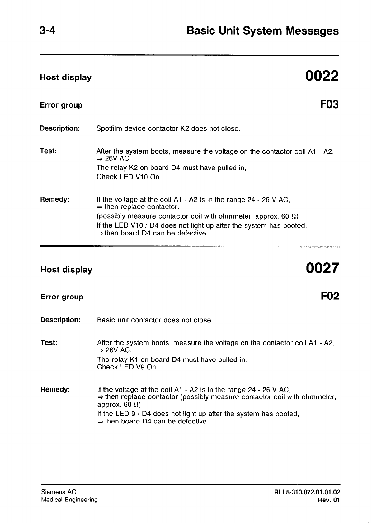
Spotfilm device contactor K2 does not close.
After the system boots, measure the voltage on the contactor coil Al - A2,
+ 26V AC
The relay K2 on board D4 must have pulled in,
Check LED VlO On.
If the voltage at the coil Al - A2 is in the range 24 - 26 V AC,
+ then replace contactor.
(possibly measure contactor coil with ohmmeter, approx. 60 Q)
If the LED VlO / D4 does not light up after the system has booted,
+ then board D4 can be defective.
0027
F02
Description:
Test:
Remedy:
Siemens AG
Medical Engineering
Basic unit contactor does not close.
After the system boots, measure the voltage on the contactor coil Al - A2,
+ 26V AC.
The relay Kl on board D4 must have pulled in,
Check LED V9 On.
If the voltage at the coil Al - A2 is in the range 24 - 26 V AC,
* then replace contactor (possibly measure contactor coil with ohmmeter,
approx. 60 52)
If the LED 9 / D4 does not light up after the system has booted,
+ then board D4 can be defective.
RLL5310.072.01.01.02
Rev.
01
Basic Unit System Messages
Host display
Error group
3-5
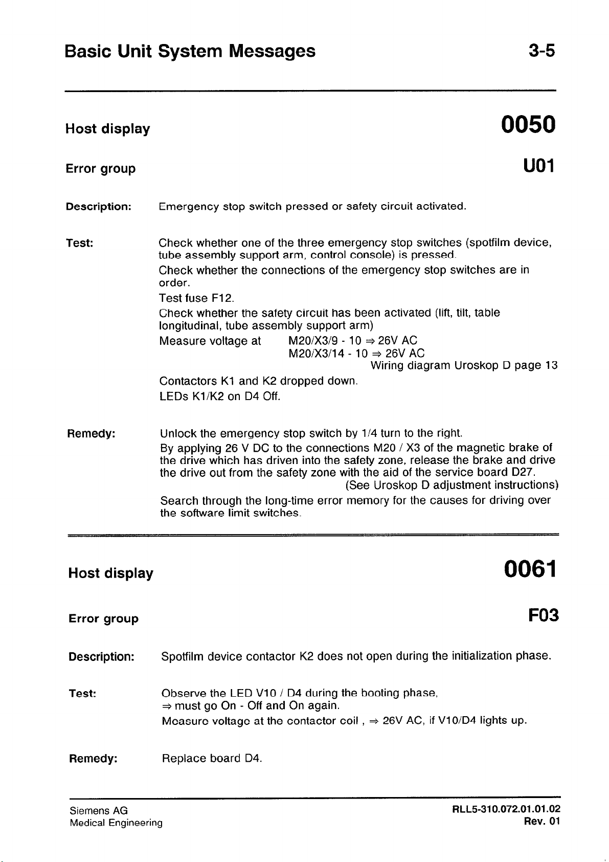
Description:
Test:
Remedy:
Emergency stop switch pressed or safety circuit activated.
Check whether one of the three emergency stop switches (spotfilm device,
tube assembly support arm, control console) is pressed.
Check whether the connections of the emergency stop switches are in
order.
Test fuse F12.
Check whether the safety circuit has been activated (lift, tilt, table
longitudinal, tube assembly support arm)
Measure voltage at
Contactors Kl and K2 dropped down.
LEDs Kl/K2 on D4 Off.
Unlock the emergency stop switch by l/4 turn to the right.
By applying 26 V DC to the connections M20 / X3 of the magnetic brake of
the drive which has driven into the safety zone, release the brake and drive
the drive out from the safety zone with the aid of the service board D27.
Search through the long-time error memory for the causes for driving over
the software limit switches.
M20/X3/9 - 10 + 26V AC
M20/X3/14 - 10 + 26V AC
Wiring diagram Uroskop D page 13
(See Uroskop D adjustment instructions)
Host display
Error group
Description:
Test:
Remedy:
Siemens AG
Medical Engineering
0061
F03
Spotfilm device contactor K2 does not open during the initialization phase.
Observe the LED VlO / D4 during the booting phase,
+ must go On - Off and On again.
Measure voltage at the contactor coil , + 26V AC, if VlO/D4 lights up.
Replace board D4.
FILL531 0.072.01.01.02
Rev. 01
3-6
Basic Unit System Messages
Host display
Error group
Description:
Test:
Remedy:
Host display
Error group
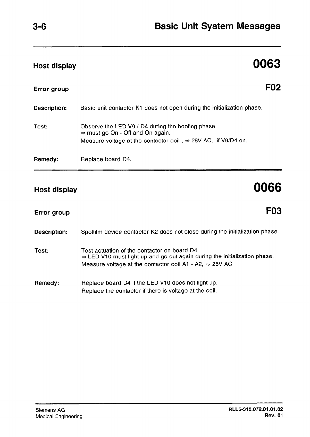
0063
F02
Basic unit contactor Kl does not open during the initialization phase.
Observe the LED V9 / D4 during the booting phase,
+ must go On - Off and On again.
Measure voltage at the contactor coil , + 26V AC, if V9/D4 on.
Replace board D4.
0066
F03
Description:
Test:
Remedy:
Spotfilm device contactor K2 does not close during the initialization phase.
Test actuation of the contactor on board D4,
+ LED VlO must light up and go out again during the initialization phase.
Measure voltage at the contactor coil Al - A2, * 26V AC
Replace board D4 if the LED VlO does not light
Replace the contactor if there is voltage at the coil.
up.
Siemens
Medical Engineering
AG
RLL5310.072.01 .01.02
Rev. 01
Basic Unit System Messages
Host display
3-7
Error group
Description:
Test:
Remedy:
Host display
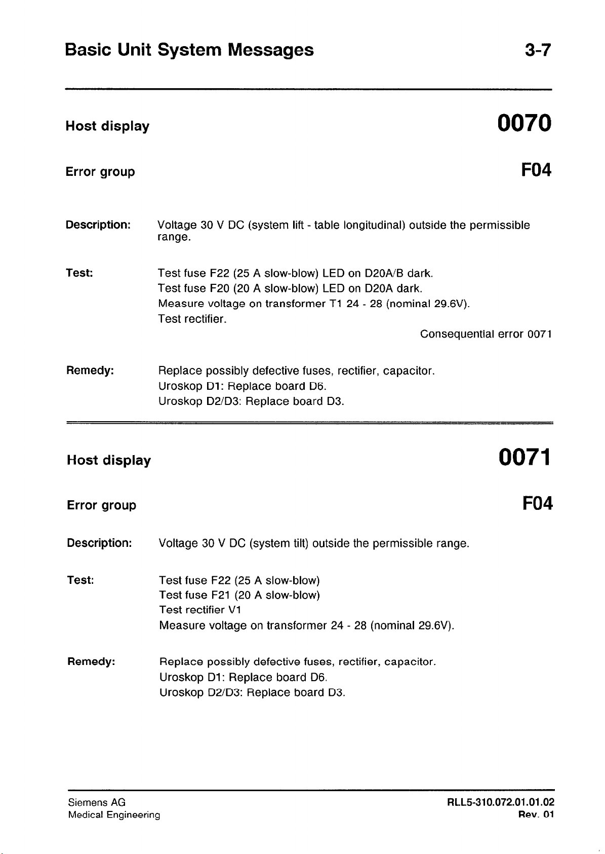
F04
Voltage 30 V DC (system lift - table longitudinal) outside the permissible
range.
Test fuse F22 (25 A slow-blow) LED on D20A/B dark.
Test fuse F20 (20 A slow-blow) LED on D20A dark.
Measure voltage on transformer Tl 24 - 28 (nominal 29.6V).
Test rectifier.
Consequential error 0071
Replace possibly defective fuses, rectifier, capacitor.
Uroskop Dl: Replace board D6.
Uroskop D2/D3: Replace board D3.
0071
Error group
Description:
Test:
Remedy:
F04
Voltage 30 V DC (system tilt) outside the permissible range.
Test fuse F22 (25 A slow-blow)
Test fuse F21 (20 A slow-blow)
Test rectifier Vl
Measure voltage on transformer 24 - 28 (nominal 29.6V).
Replace possibly defective fuses, rectifier, capacitor.
Uroskop Dl: Replace board D6.
Uroskop D2/D3: Replace board D3.
Siemens AG
Medical Engineering
RLL5-310.072.01.01.02
Rev. 01
3-8
Host display
Basic Unit System Messages
Error group
Description:
Test:
Remedy:
Host display
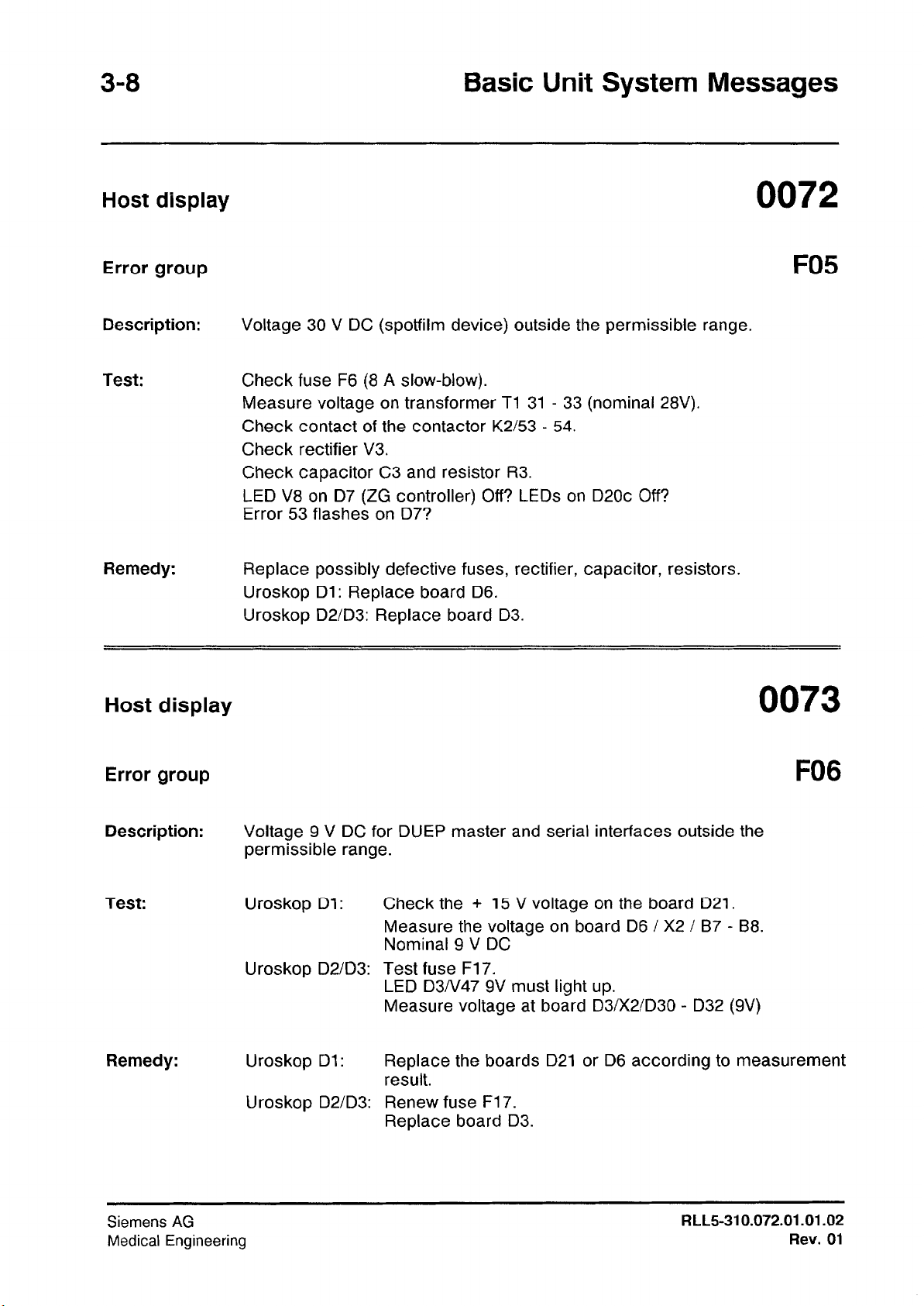
F05
Voltage 30 V DC (spotfilm device) outside the permissible range.
Check fuse F6 (8 A slow-blow).
Measure voltage on transformer Tl 31 - 33 (nominal 28V).
Check contact of the contactor K2/53 - 54.
Check rectifier V3.
Check capacitor C3 and resistor R3.
LED V8 on D7 (ZG controller) Off? LEDs on D20c Off?
Error 53 flashes on D7?
Replace possibly defective fuses, rectifier, capacitor, resistors.
Uroskop Dl: Replace board D6.
Uroskop D2/D3: Replace board D3.
Error group
Description:
Test:
Remedy:
Siemens AG
Medical Engineering
Voltage 9 V DC for DUEP master and serial interfaces outside the
permissible range.
Uroskop Dl: Check the + 15 V voltage on the board D21.
Measure the voltage on board D6 / X2 i B7 - B8.
Nominal 9 V DC
Uroskop D2/D3: Test fuse F17.
LED D3/V47 9V must light up.
Measure voltage at board D3/X2/D30 - D32 (9V)
Uroskop Dl:
Uroskop D2/D3: Renew fuse F17.
Replace the boards D21 or D6 according to measurement
result.
Replace board D3.
RLL5-310.072.01 .01.02
FO6
Rev. 01
Basic Unit System Messages
Host display
3-9
Error group
Description:
Test:
Remedy:
Host display
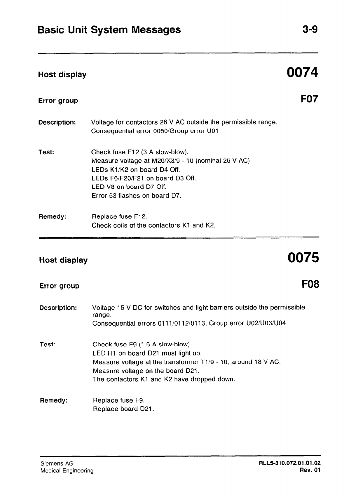
F07
Voltage for contactors 26 V AC outside the permissible range.
Consequential error 0050iGroup error UOl
Check fuse F12 (3 A slow-blow).
Measure voltage at M20/X3/9 - 10 (nominal 26 V AC)
LEDs Kl/K2 on board D4 Off.
LEDs F6/F2O/F21 on board D3 Off.
LED V8 on board D7 Off.
Error 53 flashes on board 07.
Replace fuse F12.
Check coils of the contactors Kl and K2.
Error group
Description:
Test:
Remedy:
FO8
Voltage 15 V DC for switches and light barriers outside the permissible
range.
Consequential errors 011 l/01 12/0113, Group error UO2NO3NO4
Check fuse F9 (1.6 A slow-blow).
LED Hl on board D21 must light up.
Measure voltage at the transformer T1/9 - 10, around 18 V AC.
Measure voltage on the board D21.
The contactors Kl and K2 have dropped down.
Replace fuse F9.
Replace board 021.
Siemens AG
Medical Engineering
RLL5-310.072.01 .01.02
Rev. 01
3-I 0
Basic Unit System Messages
Host display
Error group
Description:
Test:
Remedy:
Host display
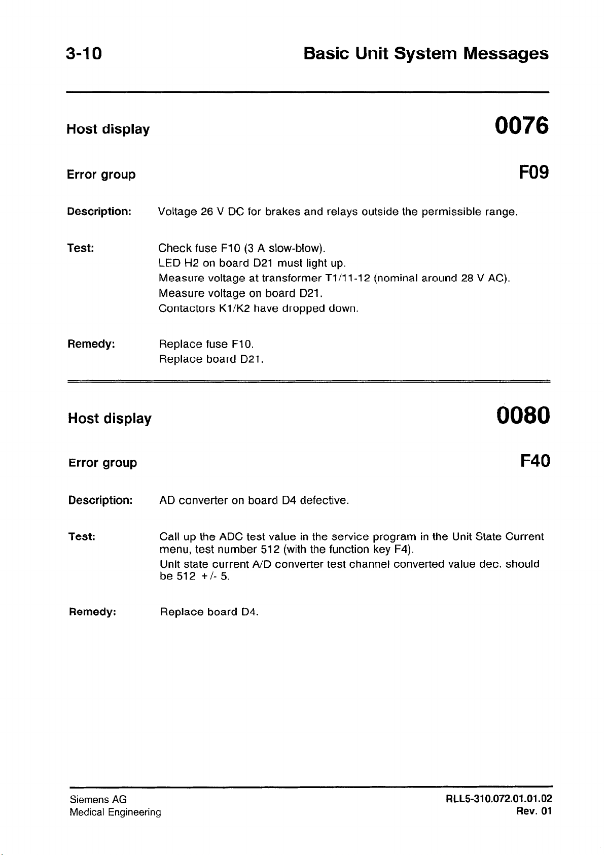
0076
FO9
Voltage 26 V DC for brakes and relays outside the permissible range.
Check fuse FlO (3 A slow-blow).
LED H2 on board D21 must light up.
Measure voltage at transformer Tl/l l-l 2 (nominal around 28 V AC).
Measure voltage on board D21.
Contactors Kl/K2 have dropped down.
Replace fuse FlO.
Replace board D21.
Error group
Description:
Test:
Remedy:
AD converter on board D4 defective.
Call up the ADC test value in the service program in the Unit State Current
menu, test number 512 (with the function key F4).
Unit state current A/D converter test channel converted value dec. should
be 512 +/- 5.
Replace board D4.
Siemens AG
Medical Engineering
RLL5-310.072.01 .01.02
Rev. 01
Basic Unit System Messages
Host display
Error group
Description:
Test:
Remedy:
Host display
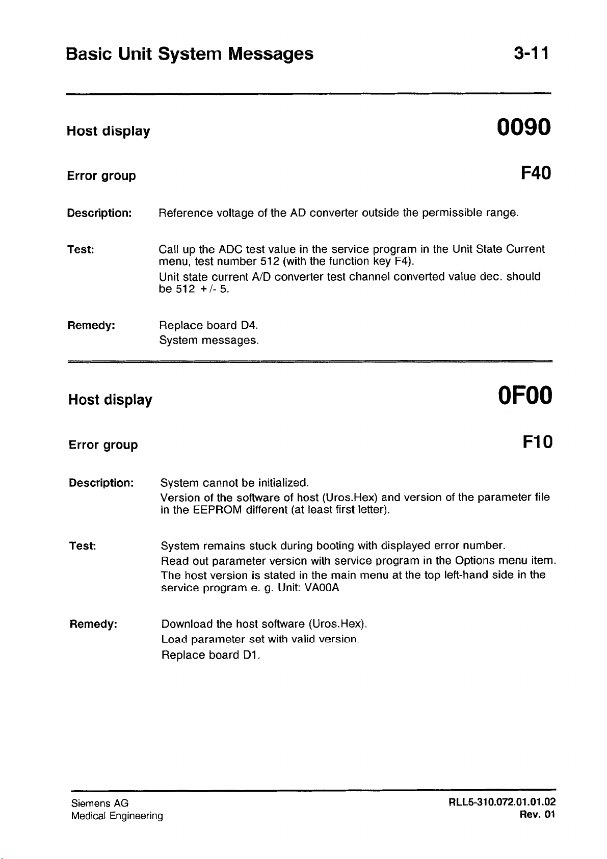
0090
F40
Reference voltage of the AD converter outside the permissible range.
Call up the ADC test value in the service program in the Unit State Current
menu, test number 512 (with the function key F4).
Unit state current A/D converter test channel converted value dec. should
be 512 +/- 5.
Replace board D4.
System messages.
Error group
Description:
Test:
Remedy:
System cannot be initialized.
Version of the software of host (Uros.Hex) and version of the parameter file
in the EEPROM different (at least first letter).
System remains stuck during booting with displayed error number.
Read out parameter version with service program in the Options menu item.
The host version is stated in the main menu at the top left-hand side in the
service program e. g. Unit: VAOOA
Download the host software (Uros.Hex).
Load parameter set with valid version.
Replace board Dl.
Siemens AG
Medical Engineering
RLL5-310.072.01.01.02
Rev.
01
Host display
Basic Unit System Messages
Error group
Description:
Test:
Remedy:
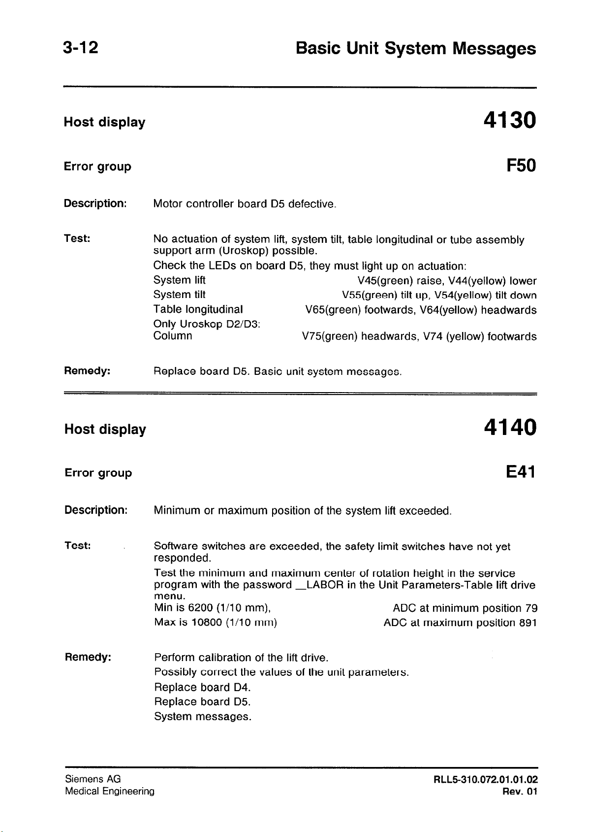
Host display
F50
Motor controller board
No actuation of system lift, system tilt, table longitudinal or tube assembly
support arm (Uroskop) possible.
Check the LEDs on board D5, they must light up on actuation:
System lift
System tilt
Table longitudinal
Only Uroskop D2/D3:
Column
Replace board D5. Basic unit system messages.
D5
defective.
V45(green) raise, V44(yellow) lower
V55(green) tilt up, V54(yellow) tilt down
V65(green) footwards, V64(yellow) headwards
V75(green) headwards, V74 (yellow) footwards
Error group
Description:
Test:
Remedy:
Minimum or maximum position of the system lift exceeded.
Software switches are exceeded, the safety limit switches have not yet
responded.
Test the minimum and maximum center of rotation height in the service
program with the password -LABOR in the Unit Parameters-Table lift drive
menu.
Min is 6200 (l/l0 mm),
Max is 10800 (l/l0 mm)
Perform calibration of the lift drive.
Possibly correct the values of the unit parameters.
Replace board D4.
Replace board D5.
System messages.
ADC at minimum position 79
ADC at maximum position 891
Siemens AG
Medical Engineering
RLL5-310.072.01.01.02
Rev.01
 Loading...