

Page 1
SU200
Distributed I/O Unit
for MC-based Substation Control Systems
User manual
Order no: LGW : AB03 - Y200A – A
Page 2

Page: 2 of 103
Version: 11
Date: 17.Oct 2002
Order no: AB03-Y200-A
SU200 User manual
This document is confidential and is the property of Siemens AS. It may not be
copied, reproduced, or disclosed in any form without the express written
consent of Siemens AS. Offenders are liable to the payment of damages. All
rights are reserved in the event of the grant of patent or the registration
Version history
Version Date Comment
1 1. Feb 1997 Initial version.
2 15. Sep 1997 Document reformatted.
New functionality in SU200DIA V2.13.
3 26. Jan 1998 Encoding of bits used for selecting active/passive master corrected.
4 16. Nov 1999 Rewritten for SU200 software release 3.0
5 08. Jan 2001 New option for 220VAC Relay Output Voltage.
6 30.Aug 2001 Rule file syntax enhanced.
7 22.Nov 2001 Latch programming example for rule file revised
8 14.May 2002 New system message indicating analogue input card faulty.
Firmware version 3.10
9 05.Jun 2002 New fail-to-safe configuration and analogue input scaling in SU200DIA described
Firmware version 3.40
10 14.Jun 2002 New version of SU200DIA (V 3.50.1)
11 17.Oct 2002 Message 103 is no longer a common message (sent on PROFIBUS)
Siemens AS reserves the right to make technical alterations. The information contained in this manual is not binding
Copyright Siemens AS 1997-2002. All Rights Reserved
Table of contents
1. Introduction ________________________________________________________________ 8
1.1. Application ____________________________________________________________________ 8
1.2. Features_______________________________________________________________________ 9
1.3. Interfaces_____________________________________________________________________ 10
2. Technical data______________________________________________________________ 11
2.1. General data __________________________________________________________________ 11
2.1.1. Digital inputs______________________________________________________________________ 11
2.1.2. Relay outputs______________________________________________________________________ 11
2.1.3. Analogue inputs____________________________________________________________________ 11
2.1.4. Power supply______________________________________________________________________ 12
2.1.5. Processors ________________________________________________________________________ 12
2.1.6. Time synchronising inputs ___________________________________________________________ 13
2.1.7. Fieldbus interfaces for optical transmission media _________________________________________ 13
2.1.8. Fieldbus interfaces for electrical transmission media _______________________________________ 13
2.1.9. Serial interface for parameterisation and diagnostics _______________________________________ 14
Page 3

SU200 User manual
This document is confidential and is the property of Siemens AS. It may not
be copied, reproduced, or disclosed in any form without the express written
consent of Siemens AS. Offenders are liable to the payment of damages. All
rights are reserved in the event of the grant of patent or the registration
Page: 3 of 103
Version: 11
Date: 17.Oct 2002
Order no: AB03-Y200-A
2.1.10. Serial interface for firmware download__________________________________________________ 14
2.1.11. LED indications____________________________________________________________________ 14
2.1.12. Electromagnetic compatibility and interference immunity ___________________________________ 14
2.1.13. Climatic strain _____________________________________________________________________ 15
2.1.14. Mechanical stress __________________________________________________________________ 15
2.1.15. Dielectric strength __________________________________________________________________ 16
2.1.16. Equipment design __________________________________________________________________ 16
2.1.17. Conformity _______________________________________________________________________ 16
2.2. Memory capacity ______________________________________________________________ 16
2.3. Ordering data _________________________________________________________________ 17
2.4. Block diagram_________________________________________________________________ 18
3. Design 19
3.1. Construction __________________________________________________________________ 19
3.2. Modules ______________________________________________________________________ 20
3.2.1. Power supply module _______________________________________________________________ 20
3.2.2. CPU and communications module _____________________________________________________ 21
3.2.3. LED module ______________________________________________________________________ 22
3.2.4. Relay output module ________________________________________________________________ 23
3.2.4.1. Relay output monitoring _________________________________________________________ 24
3.2.4.2. Relay output circuitry ___________________________________________________________ 24
3.2.5. Digital input module ________________________________________________________________ 25
3.2.5.1. Electrical time synchronisation port ________________________________________________ 26
3.2.6. Analogue input module______________________________________________________________ 26
3.3. Dimensions ___________________________________________________________________ 28
3.4. Connections ___________________________________________________________________ 28
4. Method of operation _________________________________________________________ 31
4.1. Operation principle ____________________________________________________________ 31
4.2. Self-monitoring ________________________________________________________________ 31
4.3. Redundancy __________________________________________________________________ 32
4.4. Data transfer __________________________________________________________________ 33
4.4.1. Fieldbus__________________________________________________________________________ 33
4.4.2. Network configuration ______________________________________________________________ 33
4.4.3. Principle of operation _______________________________________________________________ 33
4.4.4. Transmission media_________________________________________________________________ 33
4.4.5. Electrical transmission media _________________________________________________________ 34
4.4.6. Optical transmission media ___________________________________________________________ 34
4.5. Telegram structure_____________________________________________________________ 34
4.5.1. From SU200 to Master ______________________________________________________________ 34
4.5.2. From master to SU200 ______________________________________________________________ 38
4.6. Communications control ________________________________________________________ 38
4.6.1. From SU200 to master ______________________________________________________________ 38
4.6.1.1. Control byte #1 ________________________________________________________________ 39
4.6.1.2. Control byte #2 ________________________________________________________________ 40
4.6.2. From master to SU200 ______________________________________________________________ 41
4.6.2.1. Control byte #1 ________________________________________________________________ 41
4.6.2.2. Control byte #2 ________________________________________________________________ 42
4.6.3. Communications monitoring__________________________________________________________ 42
4.7. Cyclic buffer __________________________________________________________________ 42
Page 4

Page: 4 of 103
Version: 11
Date: 17.Oct 2002
Order no: AB03-Y200-A
SU200 User manual
This document is confidential and is the property of Siemens AS. It may not be
copied, reproduced, or disclosed in any form without the express written
consent of Siemens AS. Offenders are liable to the payment of damages. All
rights are reserved in the event of the grant of patent or the registration
4.8. Clock control__________________________________________________________________ 42
5. Controls and displays ________________________________________________________ 44
5.1. LED display __________________________________________________________________ 44
5.2. Buttons_______________________________________________________________________ 47
5.3. Serial interfaces _______________________________________________________________47
6. SU200DIA _________________________________________________________________ 48
6.1. Parameterisation ______________________________________________________________ 49
6.1.1. PROFIBUS address_________________________________________________________________ 50
6.1.2. Master mode ______________________________________________________________________ 50
6.1.3. Enable analogue inputs ______________________________________________________________ 50
6.1.4. Signal ID _________________________________________________________________________ 51
6.1.5. LED_____________________________________________________________________________ 51
6.1.6. Logic ____________________________________________________________________________ 52
6.1.7. Mode ____________________________________________________________________________ 52
6.1.8. Timing___________________________________________________________________________ 52
6.1.9. Default parameter values_____________________________________________________________ 53
6.1.10. Managing parameter files ____________________________________________________________ 53
6.2. Diagnostics ___________________________________________________________________ 54
6.2.1. Firmware version___________________________________________________________________ 54
6.2.2. Date and time _____________________________________________________________________ 54
6.2.3. Message list_______________________________________________________________________ 55
6.2.4. Digital inputs______________________________________________________________________ 56
6.2.5. Analogue inputs____________________________________________________________________ 56
6.2.6. Managing message files _____________________________________________________________ 56
6.3. Tools menu ___________________________________________________________________ 57
6.3.1. Local Control _____________________________________________________________________ 58
6.3.2. Simulate Digital Inputs ______________________________________________________________ 59
6.3.3. Fail-To-Safe configuration ___________________________________________________________ 60
6.3.4. Impulse counter values ______________________________________________________________ 60
6.3.5. Analogue input scaling ______________________________________________________________ 61
6.3.6. System parameters__________________________________________________________________ 62
6.3.7. Rules ____________________________________________________________________________ 63
6.3.7.1. Example of rules:_______________________________________________________________ 65
6.3.7.2. SET function __________________________________________________________________ 66
6.3.7.3. RESET function _______________________________________________________________ 66
6.3.7.4. BLOCK function_______________________________________________________________ 66
6.3.7.5. ABLOCK function _____________________________________________________________ 66
6.3.7.6. ENABLE function______________________________________________________________ 66
6.3.7.7. AENABLE function ____________________________________________________________ 66
6.3.7.8. Rule file macros _______________________________________________________________ 66
6.3.7.9. Actions when communication with active master is interrupted___________________________ 67
6.3.7.10. Override rule control in local mode_________________________________________________ 67
6.3.7.11. Rule download report ___________________________________________________________ 67
6.3.7.12. Priority_______________________________________________________________________ 67
6.3.7.13. Rule file syntax ________________________________________________________________ 68
6.3.7.14. Rule file example_______________________________________________________________ 70
6.3.8. Communication____________________________________________________________________ 71
6.3.9. Firmware tool _____________________________________________________________________ 72
6.3.10. Reading/writing memory or I/O-ports___________________________________________________ 72
6.3.11. Downloading new firmware __________________________________________________________ 74
7. Installation ________________________________________________________________ 75
7.1. Unpacking ____________________________________________________________________ 75
Page 5

SU200 User manual
This document is confidential and is the property of Siemens AS. It may not
be copied, reproduced, or disclosed in any form without the express written
consent of Siemens AS. Offenders are liable to the payment of damages. All
rights are reserved in the event of the grant of patent or the registration
Page: 5 of 103
Version: 11
Date: 17.Oct 2002
Order no: AB03-Y200-A
7.2. Mounting _____________________________________________________________________ 75
7.3. Connection ___________________________________________________________________ 76
7.3.1. Earth connection ___________________________________________________________________ 76
7.3.2. Connection of control wires __________________________________________________________ 76
7.3.3. Connection of optical data lines (fieldbus) _______________________________________________ 77
7.3.4. Connection of electrical data lines (fieldbus) _____________________________________________ 78
7.3.5. Cable entry fitting __________________________________________________________________ 81
7.3.6. Connecting points __________________________________________________________________ 82
8. Commissioning _____________________________________________________________ 83
8.1. General ______________________________________________________________________ 83
8.2. Checking the auxiliary power supply ______________________________________________ 83
8.3. Checking the fieldbus link _______________________________________________________ 83
8.4. Checking the clock control and time synchronisation ________________________________ 84
8.4.1. Checking the clock control ___________________________________________________________ 84
8.4.2. Checking the time synchronisation _____________________________________________________ 84
8.5. Checking the digital input _______________________________________________________ 84
8.6. Checking the command output ___________________________________________________85
8.7. Checking the analogue inputs ____________________________________________________ 85
8.8. Checking the self-monitoring function_____________________________________________ 85
9. Maintenance and fault tracing_________________________________________________ 87
Appendix A SU200DIA Parameter-files _____________________________________________ 88
Appendix B DIP switches ________________________________________________________ 90
Appendix C PROFIBUS Test Tool _________________________________________________ 92
C.1. Setting up the PROFIBUS network _______________________________________________ 94
C.1.1. Setting up PROFIBUS master card CP5613 ______________________________________________ 94
C.1.2. Setting up PROFIBUS master card CP5412 ______________________________________________ 95
C.2. Configuring and using the COM PROFIBUS application from Siemens AG _____________ 96
C.2.1. SU200 GSD file ___________________________________________________________________ 97
C.2.2. Creating a PROFIBUS network set-up for SU200 _________________________________________ 97
Appendix DReplacing FLASH memory devices _____________________________________ 100
Appendix E General Terminal Diagram____________________________________________ 101
Appendix F Connection diagram for power supply / communications____________________ 102
Appendix GConnection diagram for I/O ___________________________________________ 103
Figures
Figure 1 - Principle arrangement of a station control and monitoring system with incorporated SU200 9
Figure 2 - Overview 10
Figure 3 - Memory map 16
Figure 4 - Block diagram 18
Figure 5 - Modular arrangement of SU200 20
Figure 6 - Layout of power supplies modules 21
Figure 7 - Layout of CPU and communications module 22
Page 6

Page: 6 of 103
Version: 11
Date: 17.Oct 2002
Order no: AB03-Y200-A
SU200 User manual
This document is confidential and is the property of Siemens AS. It may not be
copied, reproduced, or disclosed in any form without the express written
consent of Siemens AS. Offenders are liable to the payment of damages. All
rights are reserved in the event of the grant of patent or the registration
Figure 8 - Layout of LED module 23
Figure 9 - Layout of relay output module 24
Figure 10 - Output circuitry 25
Figure 11 - Layout of digital input module 26
Figure 12 - Layout of analogue input module 27
Figure 13 - DIP switches for type of analogue input signal 27
Figure 14 - Dimensions 28
Figure 15 - Plug-and-socket connection of external wiring 29
Figure 16 - Types of connecting plugs with internal circuitry 30
Figure 17 - Structure of telegrams from SU200 to master 36
Figure 18 - Continued: Structure of telegrams from SU200 to master 37
Figure 19 - Structure of telegrams from master to SU200 38
Figure 20 - Arrangement of control byte #1 in telegram from SU200 to master 39
Figure 21 - Arrangement of control byte #2 in telegram from SU200 to master 40
Figure 22 - Arrangement of control byte #1 in telegram from master to SU200 41
Figure 23 - Arrangement of control byte #2 in telegram from master to SU200 42
Figure 24 - Buttons and LED’s 44
Figure 25 - Status LED's 46
Figure 26 - Start-up window of SU200DIA 48
Figure 27 - Main window of SU200DIA 49
Figure 28 - Dead- and filter time of digital inputs 52
Figure 29 - Firmware version in SU200DIA 54
Figure 30 - Date and time in SU200DIA 54
Figure 31 - Message list in SU200DIA 55
Figure 32 - Digital inputs in SU200DIA 56
Figure 33 - Analogue inputs in SU200DIA 56
Figure 34 - The Tools menu in SU200DIA 57
Figure 35 - Local Control in SU200DIA 58
Figure 36 - Simulate digital inputs in SU200DIA 59
Figure 37 - The fail-to-safe configuration in SU200DIA 60
Figure 38 - Impulse counters in SU200DIA 61
Figure 39 - The analogue input scaling configuration in SU200DIA 61
Figure 40 - System parameters window in SU200DIA 62
Figure 41 - Rules menu in SU200DIA 63
Figure 42 - Rule file syntax – flow control 68
Figure 43 - Rule file syntax - continued 69
Figure 44 - Setting communication port in SU200DIA 71
Figure 45 - Firmware tool 72
Figure 46- Monitor commands in firmware tool 73
Figure 47 - Serial port used for firmware download 74
Figure 48 - Mounting beads 76
Figure 49 - Plug-and-socket connection of external wiring 77
Figure 50 - Optical bus terminals 78
Figure 51 - Connection of electrical data lines 79
Figure 52 - Terminal arrangement of bus connector 80
Figure 53 - Allocation of CPU DIP switch 1 and 2 80
Figure 54 - Delivery configuration of CPU DIP switches 81
Figure 55 - Cable entry of SU200 81
Figure 56 - Connecting points of SU200 82
Figure 57 - System message 101, SU200 time not yet synchronised 84
Figure 58 - System message 101, SU200 time has been synchronised 84
Figure 59 - DIP switch 1 90
Figure 60 - DIP switch 2 90
Figure 61 - PROFIBUS Test Tool 92
Figure 62 - Checking the CP5613 card installation 95
Figure 63 - Selecting database for CP5613 95
Figure 64 - Setting the CP5412 access point 96
Figure 65 - Selecting database for CP5412 96
Figure 66 - Restarting CP5412 96
Page 7

SU200 User manual
This document is confidential and is the property of Siemens AS. It may not
be copied, reproduced, or disclosed in any form without the express written
consent of Siemens AS. Offenders are liable to the payment of damages. All
rights are reserved in the event of the grant of patent or the registration
Page: 7 of 103
Version: 11
Date: 17.Oct 2002
Order no: AB03-Y200-A
Figure 67 - COM PROFIBUS station types 97
Figure 68 - COM PROFIBUS network set-up 98
Figure 69 - Setting PROFIBUS network speed 98
Figure 70 - Exporting COM PROFIBUS network set-up to a LDB file 99
Tables
Table 1 - System messages generated by the self-monitoring facility 32
Table 2 - Transmission of various types of telegrams 35
Table 3 - OPERATION LED 44
Table 4 - POWER SUPPLY LED 45
Table 5 - INTERFACE LED’s 45
Table 6 - Setting master mode in SU200DIA 50
Table 7 - Default parameter values 53
Table 8 - Parameter menu in SU200DIA 53
Table 9 - Message menu in SU200DIA 57
Table 10 - Rules menu in SU200DIA 64
Table 11 - State variables in rules 65
Table 12 - Rule function types 65
Table 13 - Actions on communication interrupt for rule functions 67
Table 14 - Testing system messages 86
Table 15 - Parameter file format - General section 88
Table 16 - Parameter file format - Digital input signals section 88
Table 17 - Parameter file format - Extended section for versions later than 3.40 89
Table 18 - PROFIBUS Test Tool controls 94
Page 8

Page: 8 of 103
Version: 11
Date: 17.Oct 2002
Order no: AB03-Y200-A
SU200 User manual
This document is confidential and is the property of Siemens AS. It may not be
copied, reproduced, or disclosed in any form without the express written
consent of Siemens AS. Offenders are liable to the payment of damages. All
rights are reserved in the event of the grant of patent or the registration
1. Introduction
1.1. Application
The task of SU200 is to serve as a decentralised field control device in a microprocessor based station control and
monitoring system.
SU200 is developed for data collection, data pre-processing, data transfer and command output at the field control level
in medium-voltage and high-voltage substations, power stations and industrial plants.
SU200 is designed to be located in the immediate vicinity of the process with hard-wired parallel interfacing to the
various control devices Thus, a distributed intelligence ensures that process data is collected, logged and pre-processed
where it is generated.
Communications with the central control station is made via a PROFIBUS fieldbus, which offers interface for both
high-speed handling as well as for comprehensive interchange of process data.
The following functions are implemented:
• Acquisition and filtering of binary signals, e.g. from switchgear control and protection units
• Acquisition of analogue values
• Transmission of process data to the central control station
• Reception, conversion and output of relay commands from the central control station
• Time tagging and recording of messages
• Guaranteed data delivery of messages
• Self-monitoring / plausibility checking
• Monitoring of communications links
SU200 is designed to serve as part of a station control and monitoring system.
The functionality of SU200, together with an appropriate fieldbus link and the managing and co-ordinating functionality
of a central control station enables the execution of a large number of tasks.
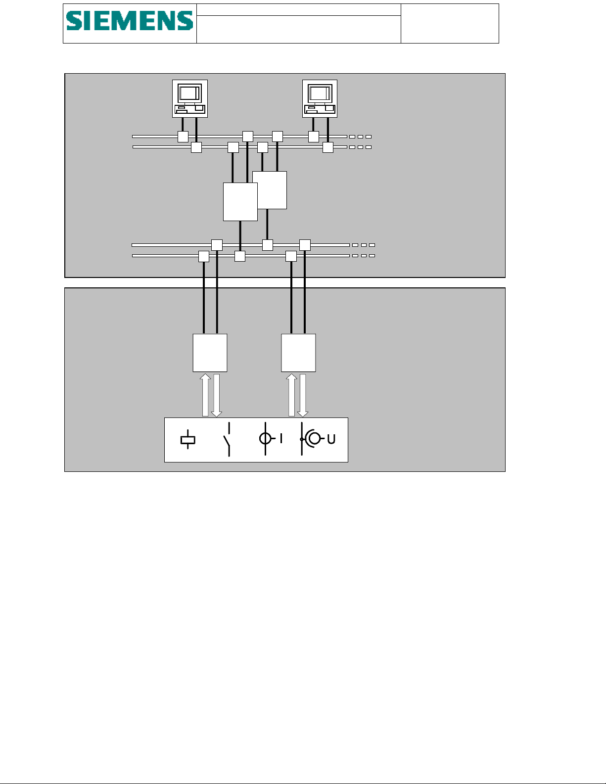
Figure 1 shows how SU200 is incorporated in a structured station control and monitoring system.
Page 9
SU200 User manual
This document is confidential and is the property of Siemens AS. It may not
be copied, reproduced, or disclosed in any form without the express written
consent of Siemens AS. Offenders are liable to the payment of damages. All
rights are reserved in the event of the grant of patent or the registration
Page: 9 of 103
Version: 11
Date: 17.Oct 2002
Order no: AB03-Y200-A
STATION
CONTROL
LEVEL
FIELD
CONTROL
LEVEL
I/O
CC
1
CC
I/O
Operator control / MMI
Local Area Network / LAN
(redundant)
Central control station
(redundant / hot standby)
Fieldbus
(redundant)
Serial interface
n
SU200
Parallel interface
Process
Figure 1 - Principle arrangement of a station control and monitoring system with incorporated SU200
1.2. Features
• Redundant power supply
• Redundant optical communications interface for multi-master configuration, hot standby
• Redundant electrical communications interface for multi-master configuration, hot standby
• Open communications interface according to PROFIBUS DP protocol standard
• Optical and electrical time synchronisation signal input
• Serial interface according to transmission standard V.24 / V.28 for easy parameterisation, diagnostics and local
control
• Serial interface according to transmission standard V.24 / V.28 for firmware upgrades and special services
• Real time task scheduling with 1 ms resolution
• Internal HW / SW clock with an accuracy of ≤ 10
• Message buffer for storage of up to 500 process messages and 50 system messages
• Digital input dead time / filter time: both configurable in the range from 1 ms. to 2500 seconds
• High availability through self-monitoring
• Error-secured output using internal plausibility checking
• Noise protected and isolated input and output circuitry
• High performance verified by way of extensive type tests and field tests (CE conformity)
-5
(36 ms/hour).
Page 10
Page: 10 of 103
Version: 11
Date: 17.Oct 2002
Order no: AB03-Y200-A
SU200 User manual
This document is confidential and is the property of Siemens AS. It may not be
copied, reproduced, or disclosed in any form without the express written
consent of Siemens AS. Offenders are liable to the payment of damages. All
rights are reserved in the event of the grant of patent or the registration
• Local display of input / output status
• Indication and signalling of internal faults
• Clear arrangement of controls and indications
• Standardised plug-in connectors for external connection
• Simple installation with the use of a pre-tested and compact unit
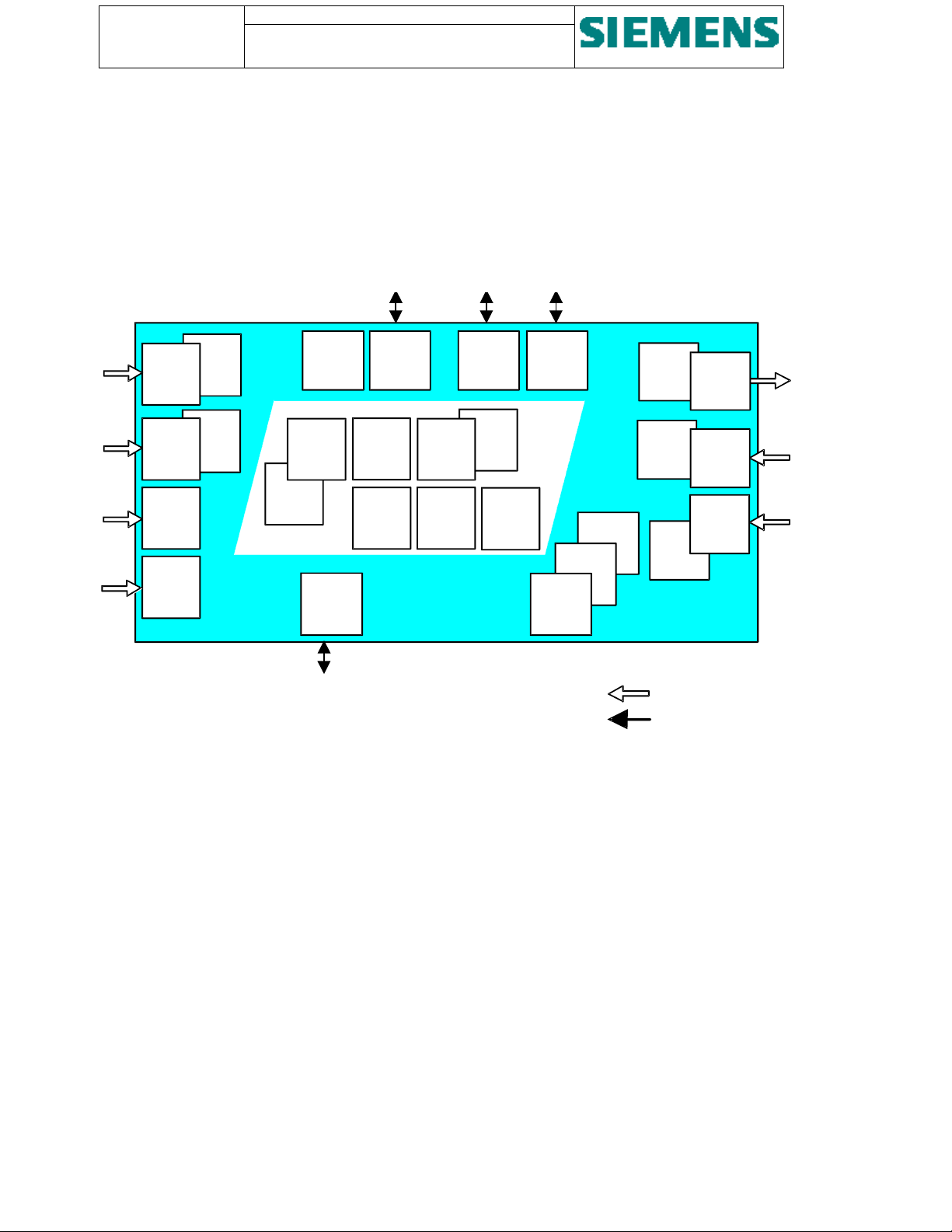
Figure 2 shows the general drawing of SU200
Power
Series
Supply
Power
# 1
Line
Filter
Power
Series
Supply
Power
# 2
Line
Filter
Electrical
Time
Synchron.
Input
Optical
Time
Synchron.
Input
Figure 2 - Overview
LED
Input /
Output
Status
Controls &
Service
Displays
Electrical
Profibus
Interface 1
RS 485
System
Software
Download
Interface
Electrical
Profibus
Interface 2
RS 485
Series
Self-
power
monitoring
line
filter
Internal
Clock
(Accuracy
36 ms/h)
Cyclic
Power
Message
Supply
Buffer
# 1
400 PM
Time
Tagging
1 ms
Optical
Profibus
Interface 1
Cyclic
Buffer
100 SM
EMC
Optical
Profibus
Interface 2
Diagnos
tics
Parameterization
Interface
Local
Control
Plausi
bility
Check
+/-20 mA
or
+/-10 V
Setting
Dead /
Filter
Time
0-250 ms
Parallel interfacing
Serial interfacing
24
Outputs
Channels
15/25 A
8
Analogue
Input
Channels
40
Digital
Input
Channels
1.3. Interfaces
Figure 2 shows all interfaces provided in SU200.
Parallel interfacing to the process (e.g. switchgear) is provided for:
• Power supply
• Switching or initiation of external control devices
• Check-back indication and alarm signalling of external control and switching devices
• Measuring of analogue values
• Time synchronisation of internal clock via electrical trigger signals
• Time synchronisation of internal clock via optical trigger signals
Serial interfaces are provided for:
• Communications with central control station
• Parameterisation, diagnostics and local control
• Downloading of system firmware
Page 11

SU200 User manual
This document is confidential and is the property of Siemens AS. It may not
be copied, reproduced, or disclosed in any form without the express written
consent of Siemens AS. Offenders are liable to the payment of damages. All
rights are reserved in the event of the grant of patent or the registration
2. Technical data
2.1. General data
2.1.1. Digital inputs
Number of inputs: 40 channels
Rated auxiliary voltage: Optional DC 24V, 110/125V, 220V
Page: 11 of 103
Version: 11
Date: 17.Oct 2002
Order no: AB03-Y200-A
Voltage range:
Signal level / voltage limits: L-signal: 0 up to 40 % of nominal value
Input dead time 1 to 2550 seconds configurable
Input filter time: 1 to 2550 seconds configurable
Power consumption per channel:
Galvanic isolation: Optocoupler
Connection: Plug-in connectors, terminal screw 4 mm
±20 % of nominal value
H-signal: 50 up to 120 % of nominal value
≈ 1.1 W (2.5 mA with 220V DC)
2.1.2. Relay outputs
Number of outputs: 24 channels / relays, each consisting of 2 NO contacts, with grouped
circuits (for common potential) of each 2 channels
Maximum switching voltage: Option 3: 225VDC / 175VAC, Standard
Option 4: 350 VDC / 275 VAC ( Ref. Ordering data )
Maximum switching current: 15 A for max. 4 seconds (channels 1 up to 22)
25 A for max. 4 seconds (channels 23 and 24)
2
Maximum continuous current: 8 A (channels 1 up to 22)
10 A (channels 23 and 24)
Switching capacity (power
rating):
Galvanic isolation: Relays
Connection: Plug-in connectors, terminal screw 4 mm
Voltage-dependent:
50 - 270 W (output channels 1 up to 22)
35 - 500 W (output channel 23 and 24)
2.1.3. Analogue inputs
Number of inputs: 8 channels
2
Page 12

Page: 12 of 103
Version: 11
Date: 17.Oct 2002
Order no: AB03-Y200-A
SU200 User manual
This document is confidential and is the property of Siemens AS. It may not be
copied, reproduced, or disclosed in any form without the express written
consent of Siemens AS. Offenders are liable to the payment of damages. All
rights are reserved in the event of the grant of patent or the registration
Rated value:
Measurement range:
Optional ±20mA or ±10V
Measuring range is converted into ±200%
Resolution: 12 bits + sign
Linearity of A/D converter:
Accuracy of A/D converter:
Measuring error:
± 1 bit
≤ 0.1 %
≤ 2% of nominal value
Dead time of input filter: 0.8 ms (20 mA input), 50 µF (10 V input)
Power consumption per channel: 20 mW (current input) / 2 mW (voltage input)
Burden per voltage / current path:
50 kΩ (voltage input) / 200 Ω (current input)
Galvanic isolation: Via series-connected external measuring transducer / transmitter
Connection: Plug-in connectors, terminal screw 2.5 mm
2.1.4. Power supply
2
Number of supplies: 2 (parallel operation)
Rated voltage: Optional DC 24V, 110/125V, 220V
Voltage range: 50 % up to 120 % of nominal value
Voltage ripple:
Power consumption: Approx. 16 W (quiescent)
Permissive supply interruption: 100 ms.
EMC: Series power line filter
Galvanic isolation: DC / DC-converter
Connection: Plug-in connectors, terminal screw 4 mm
2.1.5. Processors
Central Controller: 1 unit SAF 80C167 / 40 MHz
< 10%
Approx. 48 W (50% of input/output activated)
Approx. 80 W (100% of input/output activated)
115/250 V∼, 50/60 Hz, 3 A
2
(16 bit processor)
Communication: 2 units SAF 80C165 / 40 MHz
(16 bit processor used in 8 bit mode)
Watchdog: Automatic reset with failure indication
Page 13

SU200 User manual
This document is confidential and is the property of Siemens AS. It may not
be copied, reproduced, or disclosed in any form without the express written
consent of Siemens AS. Offenders are liable to the payment of damages. All
rights are reserved in the event of the grant of patent or the registration
2.1.6. Time synchronising inputs
Number of optical trigger input: 1
Page: 13 of 103
Version: 11
Date: 17.Oct 2002
Order no: AB03-Y200-A
Connection:
Optical fibre bayonet coupling / type ST
Number of electrical trigger input: 1
Signal voltage level: Optional DC 24 V, 48 V, 110/125 V, 220 V
Voltage range:
Connection: Plug-in connectors, terminal screw 4 mm
±20 % of nominal value
2
Accuracy of internal clock: 10-5 (36 ms/hour)
2.1.7. Fieldbus interfaces for optical transmission media
Transmission speed: 9.6 / 19.2 / 93.75 / 187.5 / 500 / 1500 kBaud (optional 3 / 6 / 9 / 12 MBaud)
Transmission protocol: Protocol PROFIBUS DP according to EN 50 170 part 3
32 bytes of user data for transmission
12 bytes of user data for receiving
Number of optical ports: Redundant interface:
4 bus terminals (2 receiver, 2 transmitter)
Connection:
Optical fibre bayonet coupling / type ST
Cable type: Fibre optic cables with plastic or glass fibres 62.5 / 125 µm
Optical wave length: 820 nm (glass)
Permissive line attenuation: Max. 8 dB/km
Transmission distance: Max. 2 km
2.1.8. Fieldbus interfaces for electrical transmission media
Transmission standard: RS-485
Transmission protocol: Protocol PROFIBUS DP according to EN 50 170
32 bytes of user data for transmission
12 bytes of user data for receiving
Transmission speed: 9.6 / 19.2 / 93.75 / 187.5 / 500 / 1500 kBaud (optional 3 / 6 / 9 / 12 MBaud)
Number of electrical ports: 2 (redundant)
Connection: 9-pole SUB-D-jack
Cable type: 2-core double shielded cable
Page 14

Page: 14 of 103
Version: 11
Date: 17.Oct 2002
Order no: AB03-Y200-A
SU200 User manual
This document is confidential and is the property of Siemens AS. It may not be
copied, reproduced, or disclosed in any form without the express written
consent of Siemens AS. Offenders are liable to the payment of damages. All
rights are reserved in the event of the grant of patent or the registration
2.1.9. Serial interface for parameterisation and diagnostics
Transmission standard: V.24 / V.28, RS-232
Transmission speed: 9.6 kBaud
Connection: 9-pole SUB-D-jack
Physical Layer: Emulated UART
Link Layer: SIEMENS ST1 Protocol
Hamming Distance: 4
2.1.10. Serial interface for firmware download
Transmission standard: V.24 / V.28
Transmission speed: 9.6 kBaud
Connection: 9-pole SUB-D-jack
Physical Layer: UART
Link Layer: IEC 870 Series 101
Hamming Distance: 4
2.1.11. LED indications
Digital input activated: Green LED per channel (switch-selectable)
Command output activated: Green LED per channel (switch-selectable)
Service availability: Green LED, steady light for healthy operation, blinking light (1s) for
malfunction
Power supply: Green LED, steady light for both power supply units in operation, blinking light
for failure of power supply unit 1 (2s) or unit 2 (1s)
Fieldbus communication link 1: Green LED for healthy operation
Blinking light (1s) for transmission blocked
Fieldbus communication link 2: Green LED for healthy operation
Blinking light (1s) for transmission blocked
2.1.12. Electromagnetic compatibility and interference immunity
In accordance with harmonised standard EN 50082-2, 1995 / industrial applications
Conducted HF interference:
IEC 1000-4-6 = ENV 50141
Radiated HF interference, EM-field
amplitude-modulated (1kHz):
IEC 1000-4-3 = ENV 50140
Class III
10 V, 150 kHz to 80 MHz
Class III
10 V/m, 80 to 1000 MHz
Page 15

SU200 User manual
This document is confidential and is the property of Siemens AS. It may not
be copied, reproduced, or disclosed in any form without the express written
consent of Siemens AS. Offenders are liable to the payment of damages. All
rights are reserved in the event of the grant of patent or the registration
Page: 15 of 103
Version: 11
Date: 17.Oct 2002
Order no: AB03-Y200-A
Radiated HF interference, EM-field
pulse frequency. Modulated:
Class III
10 V/m, 900 MHz
(200Hz) ENV 50204
Fast transients (burst):
IEC 1000-4-4
Lightning Impulse (surge):
IEC 1000-4-5
Class IV, 4 kV (power supply) / 2 kV (signal lines), 5/50 ns., 1 min each
polarity
Class IV , 4 kV, 1.2/50 µs (enclosure)
Class III , 2 kV, 1.2/50 µs (DC input )
Positive / negative, 1 impulse per min.
Electrostatic discharge / ESD:
IEC 1000-4-2
Radiated power frequency
interference / magnet field:
IEC 1000-4-8
Class IV , 10 positive and negative discharges,
15 kV (peak) contact, 8 kV (peak) air
Class V
100 A/m continuously
1000 A/m short-time 1 s
Higher severity of test as required per standard
If higher severity is required, an external series filter element is connected
Supplementary
HF disturbance (1 MHz-impulse):
IEC 255-22-1
Class III / 2.5 kV (peak) comm. mode / 1 kV diff., 1 MHz, 400 shots/s, duration
2 s
In accordance with harmonised standard EN 50081-2, 1995 / industrial applications
Radio interference/field intensity:
Limit class A
EN55011 / CISPR 11
2.1.13. Climatic strain
Permissive ambient temperature
- during operation: -5 to +55°C (recommended values in
-40 to +70°C (values are only guaranteed at appropriate climate conditioning
inside weather-protected cubicles)
- during storage: -25 to +55°C
- during transportation: -25 to +70°C
Permissive humidity:
Annual average ≤75 % relative humidity.
Up to 95 % relative humidity for 30 days a year.
Moisture condensation not permissible
2.1.14. Mechanical stress
Earthquake:
Vibration:
Shock: during operation: 10 g, 16 ms
during operation: 3 to 35 Hz, ±10 mm amplitude / 1,5 g acceleration
during operation: 10 to 500 Hz, ±0,15 mm amplitude / 2 g acceleration
during transportation 5 to 500 Hz, ±7,5 mm amplitude / 2 g acceleration
during transportation 15 g, 11 ms
accordance with Standard EN 60721)
Page 16
Page: 16 of 103
Version: 11
Date: 17.Oct 2002
Order no: AB03-Y200-A
SU200 User manual
This document is confidential and is the property of Siemens AS. It may not be
copied, reproduced, or disclosed in any form without the express written
consent of Siemens AS. Offenders are liable to the payment of damages. All
rights are reserved in the event of the grant of patent or the registration
2.1.15. Dielectric strength
High voltage:
2.5 kV (rms), 50 Hz, 1 min
IEC 255-5
Insulation resistance:
2 kV DC, 1 min (>100 MΩ)
IEC 255-5
Impulse voltage:
IEC 255-4
5 kV (peak), 1.2/50 µs, 0.5 J
3 positive and 3 negative shots at 5 s intervals
2.1.16. Equipment design
Dimensions:
(width x height x depth)
Weight: approx. 13 kg
Degree of protection: IP 20
486 x 298 x 220 mm (see chapter Dimensions)
2.1.17. Conformity
This product is in agreement with the requirements of the specification of the applicable council directive in relation to
electromagnetic compatibility (publication 89/336/EWG).
This device has been developed and manufactured for service in industrial plants.
This declaration of conformity is based on tests according to harmonised standards EN 50081-2 and EN 50082-2
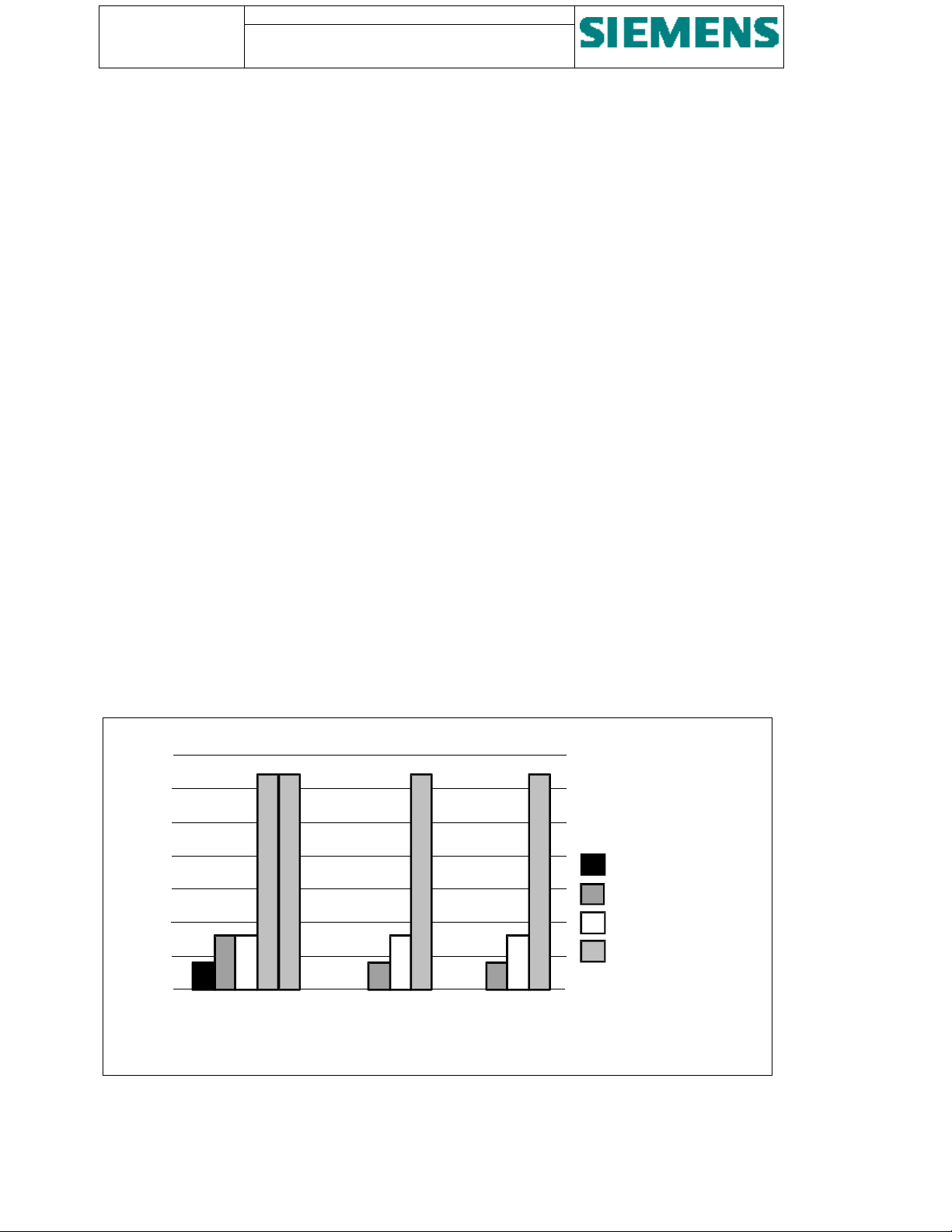
2.2. Memory capacity
kByte
140
120
100
80
60
40
20
0
Main CPU Subsystem 1
Figure 3 - Memory map
EEPROM
Dual-port RAM
RAM
Flash
Subsystem 2
Page 17
SU200 User manual
This document is confidential and is the property of Siemens AS. It may not
be copied, reproduced, or disclosed in any form without the express written
consent of Siemens AS. Offenders are liable to the payment of damages. All
rights are reserved in the event of the grant of patent or the registration
Page: 17 of 103
Version: 11
Date: 17.Oct 2002
Order no: AB03-Y200-A
2.3. Ordering data
SU200 can be supplied in 6 versions, dependent on the power supply voltage and digital input
voltage.
2 options are possible depending on the maximum Relay Output Voltage.
The analogue input module is standard.
Designation Ordering number Remark
Distributed Input/Output unit SU200
Power supply: 220V DC Digital Input: 220 V DC
Power supply: 110 / 125V DC Digital Input: 110 / 125 V DC
Power supply: 24V DC Digital Input: 24 V DC
Power supply: 110 / 125V DC Digital Input: 24 V DC
Power supply: 220 V DC Digital Input: 110 / 125 V DC
Power supply: 220 V DC Digital Input: 24 V DC
Option: With analogue input module
Without analogue input module
Maximum Relay output Voltage 225VDC/175VAC
Maximum Relay output Voltage 350VDC/275VAC
LGW: AB03-A101 -A- /AA
⇑⇑⇑⇑⇑
A
B
C
G
H
J
Diagnostic/ Parameterisation Software LGW : AB03 - Y100A - A
Complete documentation LGW : AB03 - Y200A - A
Accessories:
Bus connector (PROFIBUS) 45° cable outgoing
Bus connector (PROFIBUS) 90° cable outgoing
Bus connector (PROFIBUS) axial outgoing
Ref. Simatic Accessories
Ref. Simatic Accessories
Ref. Simatic Accessories
⇑
⇑⇑
⇑⇑⇑⇑
⇑⇑⇑⇑
⇑⇑⇑⇑
⇑⇑⇑⇑
⇑⇑⇑⇑
⇑⇑⇑⇑
⇑⇑⇑⇑
1 Obsolete
2 Obsolete
3 Standard
4
Optical link module (PROFIBUS OLM)
Plug-in connector (PHOENIX) 9-pole for binary input
Plug-in connector (PHOENIX) 6-pole for command output
Plug-in connector (PHOENIX) 6-pole for analogue input
External protective m.c.b. for SU200 auxiliary supply
circuitry
Ref. Simatic Accessories
18 04 97 5
18 04 94 6
17 57 05 1
5 SX5 201-7
5 SX2 202-7 (5 SX2 102-7)
5 SX9 100
PC 4/9-ST-7,62
PC 4/6-ST-7,62
MSTB 2,5/
6-ST-5,08
110 V-220 VDC
24 VDC
1NO,1NC
aux. contact
Page 18
Page: 18 of 103
y
g
p
p
y
y
(
)
p
g
g
(
g
Version: 11
Date: 17.Oct 2002
Order no: AB03-Y200-A
SU200 User manual
This document is confidential and is the property of Siemens AS. It may not be
copied, reproduced, or disclosed in any form without the express written
consent of Siemens AS. Offenders are liable to the payment of damages. All
rights are reserved in the event of the grant of patent or the registration
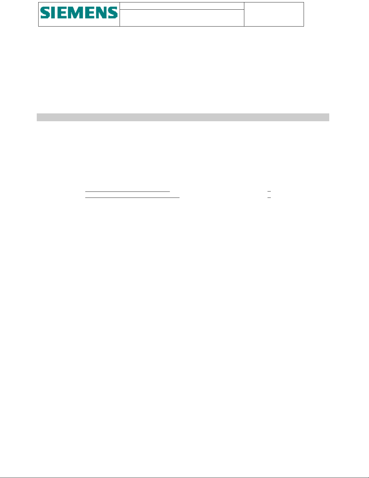
2.4. Block diagram
+
-X1:
Power suppl
circuit 1
=
-
-X11:
-X15:
1
=
2
Power supply
circuit 2
Optical
fieldbus
interface
(PROFIBUS)
Electrical
fieldbus
interface
PROFIBUS
O
tical time
synchronising
ort
Electrical time
s
nchronisin
input
Parameterisation
and diagnostics
ort
Firmware
download
interface
8 channels:
Analo
ue input
nals
si
from external
measuring
transducers or
transmitters)
-X2:
-X4:
-X6:
-X3:
-X5:
-X8:
-X7:-+
-X9:
-X10:
-X41:
-X44:
+
=
-
=
3
4
40 channels:
5
OPT.
OPT.
RS-485
9-pole
RS-485
OPT.
EL.
9-pole
V.24 /
V.28
9-pole
V.24 /
V.28
settable
(+)
1
(M)
2
(-)
(+)
(M)
(-)
channel 1
channel 2
3
4
5
6
Circuit 1
Circuit 2
Clock control
20mA
10V
Channel 1
Channel 2
6
7
8
9
1
3
5
2
4
6
-X21:
-X32:
Di
ital input
signals
24 channels:
Double
rela
output
Figure 4 - Block diagram
Page 19

SU200 User manual
This document is confidential and is the property of Siemens AS. It may not
be copied, reproduced, or disclosed in any form without the express written
consent of Siemens AS. Offenders are liable to the payment of damages. All
rights are reserved in the event of the grant of patent or the registration
Page: 19 of 103
Version: 11
Date: 17.Oct 2002
Order no: AB03-Y200-A
3. Design
3.1. Construction
SU200 is made as an enclosed compact device in an IP20 metal housing and is designed for surface mounting on
standard subrack frames or for cubicle mounting.
SU200 contains the following components:
• Power supply modules
• Processors and communications module
• LED module
• Relay output module
• Digital input module
• Analogue input module
Page 20
Page: 20 of 103
g
A
y
p
r
y
pply
Version: 11
Date: 17.Oct 2002
Order no: AB03-Y200-A
SU200 User manual
This document is confidential and is the property of Siemens AS. It may not be
copied, reproduced, or disclosed in any form without the express written
consent of Siemens AS. Offenders are liable to the payment of damages. All
rights are reserved in the event of the grant of patent or the registration
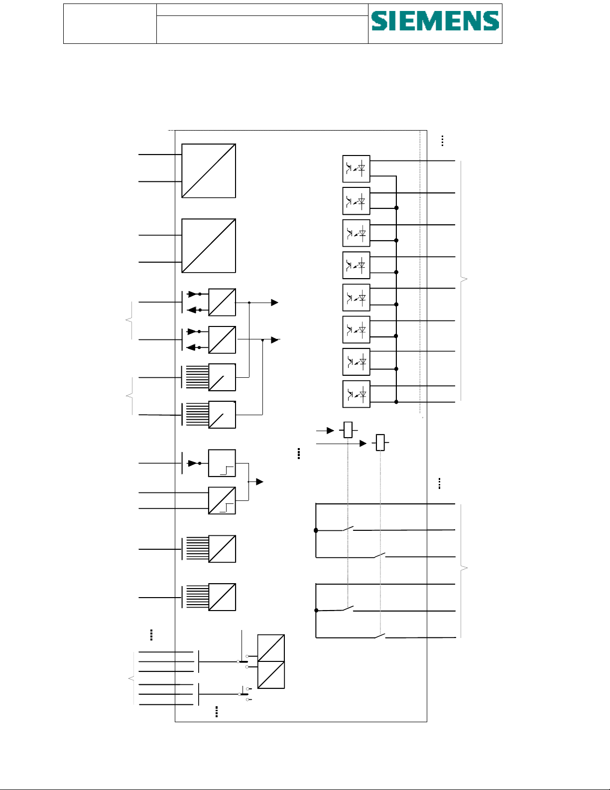
LED module
Central processin
nalogue input
module
Binar
and communications module
input module
Out
Power suppl
module 1
Filte
Figure 5 - Modular arrangement of SU200
3.2. Modules
3.2.1. Power supply module
ut module
Power su
module 2
The power supply of SU200 is arranged with two independent modules forming a redundant system. The internal
auxiliary voltages for the individual modules of SU200 are provided in a switch mode solution and distributed by way
of ribbon cable connections.
For the connection of the external power supply, 4 mm
2
plug-in connectors are provided on the input module.
The external power supply is fed through series power line filters in order to increase the interference immunity / EMC.
The device can be supplied in three versions, whereas the rated power supply can be 24 V, 110/125 V or 220 V DC.
Page 21
SU200 User manual
r
This document is confidential and is the property of Siemens AS. It may not
be copied, reproduced, or disclosed in any form without the express written
consent of Siemens AS. Offenders are liable to the payment of damages. All
rights are reserved in the event of the grant of patent or the registration
Page: 21 of 103
Version: 11
Date: 17.Oct 2002
Order no: AB03-Y200-A
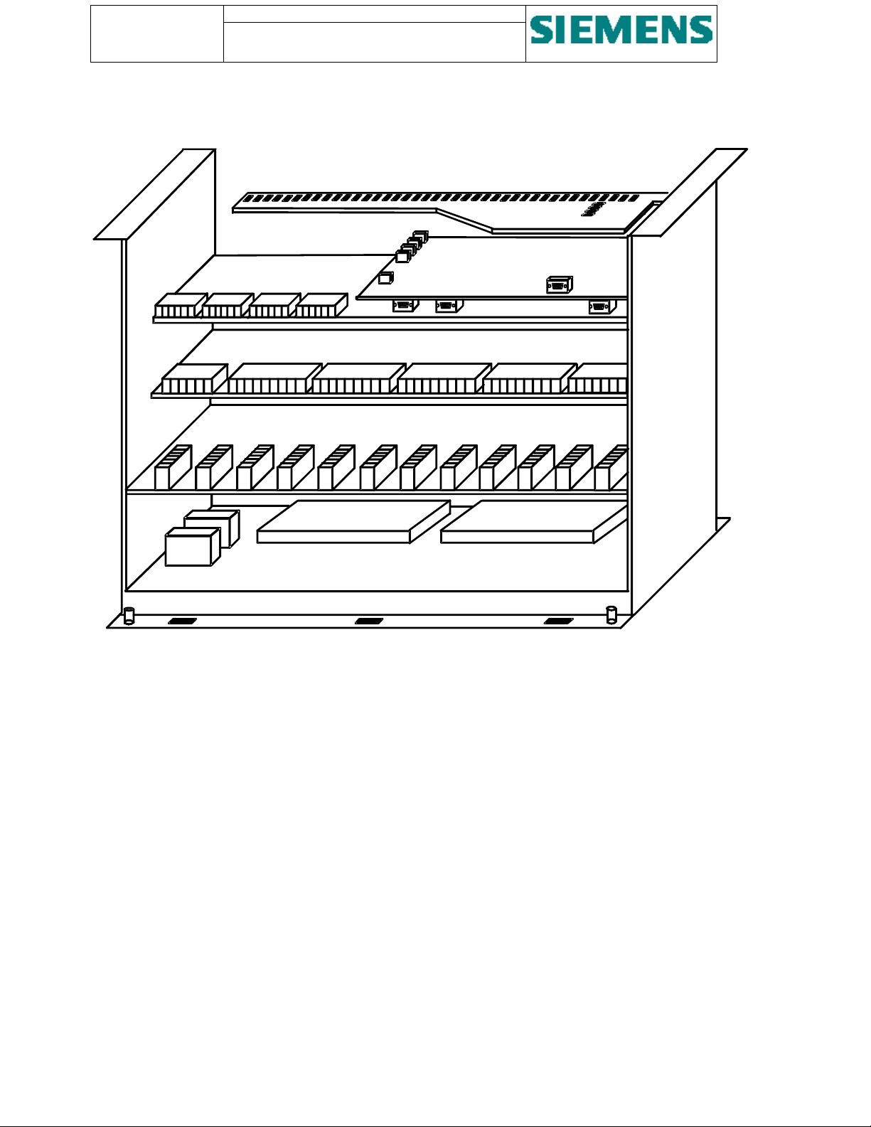
Output connector
X2
Power supply #1
Series power
line filter #1
Series power
line filter #2
Input connector
X1
Resisto
Output connector
X2
Power supply #2
(Bottom plate of SU200)
Input connector
X1
Input
connectors
Output
connectors
Figure 6 - Layout of power supplies modules
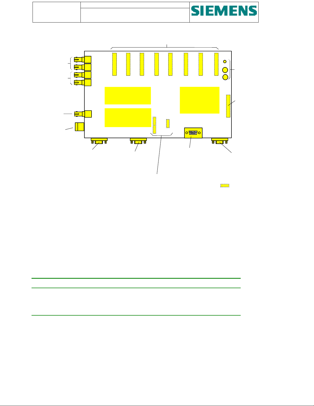
3.2.2. CPU and communications module
The central processor unit (CPU) is responsible for pre-processing of acquired process data and organising of the data
exchange with the central control station.
The microprocessor carries out a full restart on power-up and reset.
For communications with the central control station, a redundant interface for both electrical and optical data
transmission media is provided.
For the connection of a redundant fibre optic fieldbus link, four bus terminals with bayonet coupling (ST standard ports)
are provided, consisting of two receiver and two transmitter ports designed to operate with 62.5/125 µm fibre optic
cables.
The receiver incorporates an integrated photo IC containing a photo-detector and dc amplifier driving an open-collector
output transistor.
The transmitter contains an 820 nm emitter capable of efficiently launching optical power into four different optical
fibre sizes.
The receivers are easily identified by their dark grey colour; transmitters are made in light grey colour.
In addition, 2 SUB-D jacks are provided on the CPU for the connection of a redundant electrical fieldbus link.
For the open communications, the protocol PROFIBUS-DP as defined by EN 50 170, part 3 is selected.
The fieldbus interface is arranged with subsystems containing a standard PROFIBUS-DP controller and a processor,
which communicates with the main CPU via dualport RAM.
Page 22
Page: 22 of 103
y
y
Version: 11
Date: 17.Oct 2002
Order no: AB03-Y200-A
SU200 User manual
This document is confidential and is the property of Siemens AS. It may not be
copied, reproduced, or disclosed in any form without the express written
consent of Siemens AS. Offenders are liable to the payment of damages. All
rights are reserved in the event of the grant of patent or the registration
Ribbon cable connectors
Optical fieldbus
Interface #1
Optical fieldbus
Interface #2
-X4:
-X6:
X8
X7
X6
Communications
Subs
stem 1
Optical time
synchr. input
Interconnector
for the electrical
-X17:
-X8:
-X3:
Communications
Subs
stem 1
-X5:
time synchr. signal
Electrical fieldbus
Interface #1
Electrical fieldbus
Interface #2
Connectors for
auxiliary power supply
Figure 7 - Layout of CPU and communications module
X9
X5
X4
X19
X3 X2 X1
Serial interface
and diagnostics
Main CPU
-X9:
Push-buttons
Ribbon cable
connector
X16
-X10:
Serial interface
for firmware
download
... underside of board
The module is equipped with the following interfaces:
• Optical interface for fieldbus #1
• Optical interface for fieldbus #2
• Electrical interface for fieldbus #1
• Electrical interface for fieldbus #2
• Optical time synchronisation signal input
• Serial interface for parameterisation and diagnostics
• Serial interface for download of firmware
Pushbuttons are provided for:
PUSH button Action
RESET Initiates a hardware reset
LED-TEST Initiates a firmware test and indicates proper function of the LED’s
DISPLAY MODE Initiates a change-over between LED display of digital input and relay output
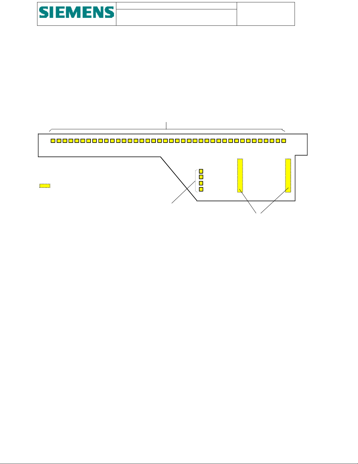
3.2.3. LED module
The LED module is attached to the CPU module via spacer sleeves and contains
• 40 LED’s to provide status indication of either the input or the output channels. The DISPLAY MODE pushbutton
can be used to toggle between indication of the input status or the output status.
• 1 LED named OPERATION to provide status indication of the operating condition and service availability of the
CPU. Steady light indicate healthy operation, blinking light indicates malfunction
Page 23
SU200 User manual
p
This document is confidential and is the property of Siemens AS. It may not
be copied, reproduced, or disclosed in any form without the express written
consent of Siemens AS. Offenders are liable to the payment of damages. All
rights are reserved in the event of the grant of patent or the registration
Page: 23 of 103
Version: 11
Date: 17.Oct 2002
Order no: AB03-Y200-A
• 1 LED named POWER SUPPLY to provide status indication of both power supply units. Steady light indicate
healthy operation, blinking light indicates malfunction
• 2 LED named INTERFACE 1 and INTERFACE 2 provides status indication of the operating condition of both
communications interfaces. Steady light indicate healthy operation, dark LED indicates communications out of
service
The interconnection to the CPU module is made via two ribbon cables.
40 LED's for input/output status indication
1 ...
... underside of board
O
erational LED's
OPERATION
POWER SUPPLY
INTERFACE 1
INTERFACE 2
... 40
Connectors to CPU board
Figure 8 - Layout of LED module
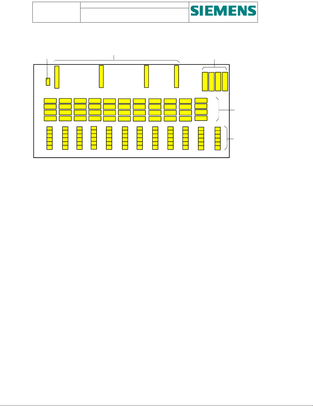
3.2.4. Relay output module
The relay output module is arranged with 24 noise protected and isolated double-command outputs.
The interconnection to the CPU module is made with four ribbon cables. For the external connection, 4 mm
connectors are provided.
The maximum switching current of 22 output channels is 15 A (4 s), 2 output channels are designed for a maximum
switching current of 25 A (4 s).
2
plug-in
Page 24
Page: 24 of 103
Version: 11
Date: 17.Oct 2002
Order no: AB03-Y200-A
Connector for
auxiliary power
supply (24 V)
SU200 User manual
This document is confidential and is the property of Siemens AS. It may not be
copied, reproduced, or disclosed in any form without the express written
consent of Siemens AS. Offenders are liable to the payment of damages. All
rights are reserved in the event of the grant of patent or the registration
Ribbon cable connectors
Output relays of
channels #23 and #24
X13
X14
X15 X16
X17
Output relays of
channels #1 up to
#22
Base sockets for
plug connectors
-X21: -X22: -X23:
-X24:
-X25: -X26:
-X27: -X28:
-X29: -X30: -X31: -X32:
Figure 9 - Layout of relay output module
3.2.4.1. Relay output monitoring
All relay output channels are monitored for correct command output.
By way of feedback circuits, the output of an individual channel is only released after a plausibility check has been
executed and the output circuitry is considered as healthy.
In case of malfunction, the respective output group (two channels) is blocked and a corresponding system message is
sent to the central control station.
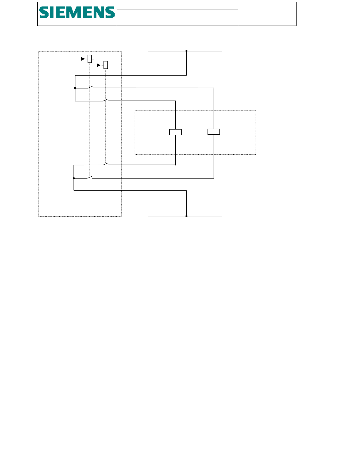
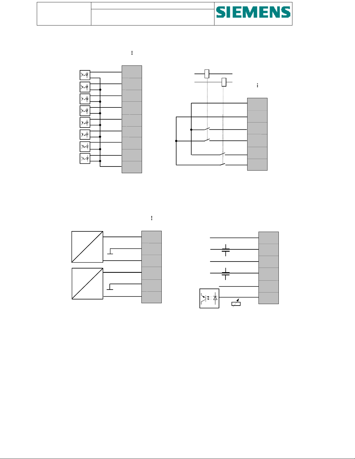
3.2.4.2. Relay output circuitry
Each relay output channel is provided with two NO (normal open) contacts.
The output channels are organised by groups of two channels. Two output channels are connected to common paths and
enable, on one hand, double-pole switching and, on the other hand, switching in both directions (e.g. closing and
opening of an external control/switching device).
Figure 10 shows the general output arrangement and a typical connection of a high voltage switching device.
Page 25
SU200 User manual
g
p
g
This document is confidential and is the property of Siemens AS. It may not
be copied, reproduced, or disclosed in any form without the express written
consent of Siemens AS. Offenders are liable to the payment of damages. All
rights are reserved in the event of the grant of patent or the registration
L+
Page: 25 of 103
Version: 11
Date: 17.Oct 2002
Order no: AB03-Y200-A
Channel #1
Channel #2
Figure 10 - Output circuitry
-X:
1
3
5
6
4
2
HV switching
device
L-
Closin
Coil
O
Coil
enin
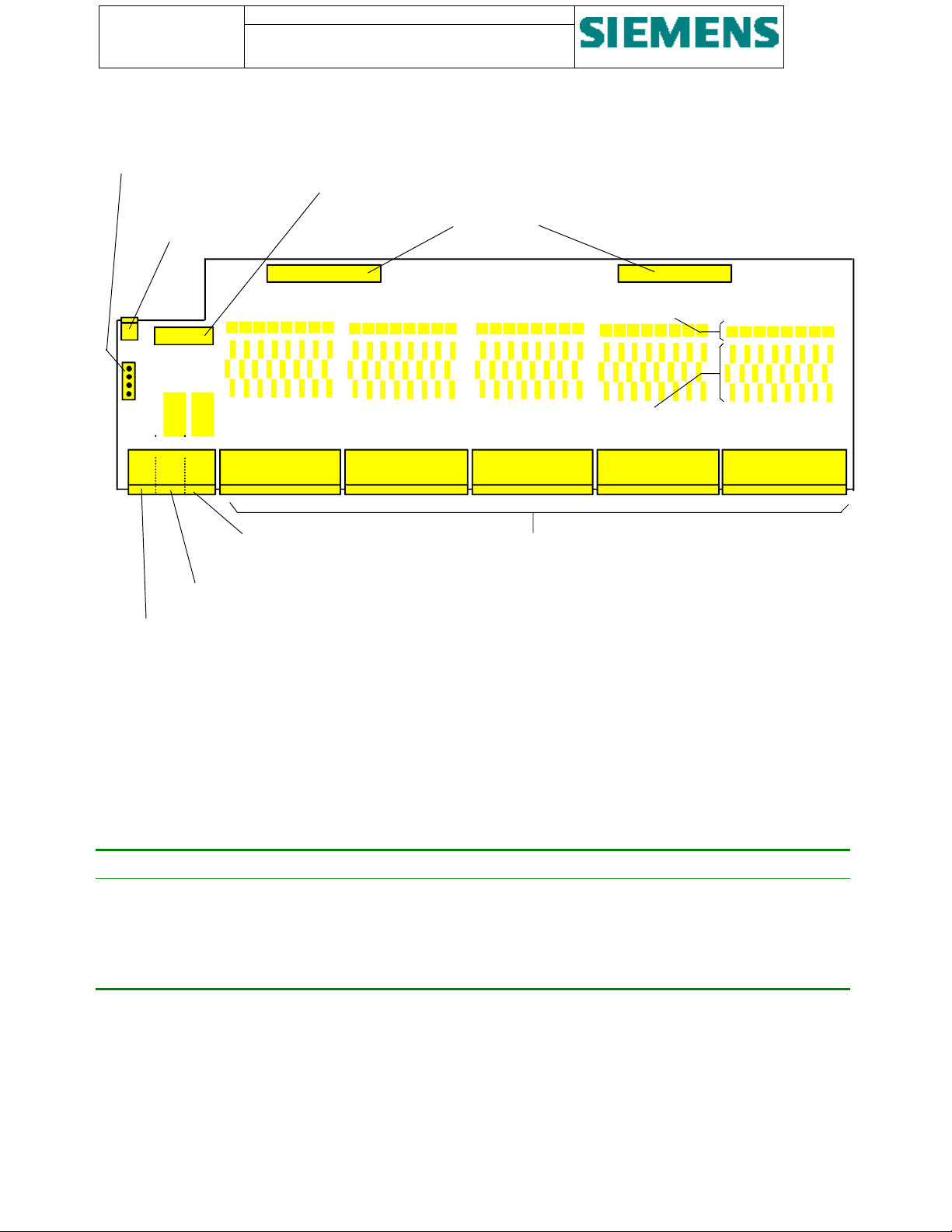
3.2.5. Digital input module
The input module contains 40 noise protected and optical isolated digital input channels and can be supplied in three
versions for external signal voltage 24 V, 110/125 V and 220 VDC.
The interconnection to the CPU module is made with two ribbon cables. For the external connection, 4 mm
connectors are provided.
The input circuitry is provided in a grouped form. A group of eight digital input channels are connected to one common
path.
In addition, the electrical time synchronisation input and the two power supply inputs are provided on the input module.
2
plug-in
Page 26
Page: 26 of 103
Version: 11
Date: 17.Oct 2002
Order no: AB03-Y200-A
Link connector for
adaptation of electrical
time synchr. signal
Interconnector for
the electrical
time synchr. signal
SU200 User manual
This document is confidential and is the property of Siemens AS. It may not be
copied, reproduced, or disclosed in any form without the express written
consent of Siemens AS. Offenders are liable to the payment of damages. All
rights are reserved in the event of the grant of patent or the registration
Interconnector for
auxiliary
power supply
Ribbon cable connectors
X7
X8
Optocouplers
X11
X10
X9
Resistance network
-X7: -X1: -X2: -X11: -X12: -X13: -X14: -X15:
Base socket for
external power supply input 2
Base sockets for
binary signal input
Base socket for
external power supply input 1
Base socket for
electrical time synchr.
signal input
Figure 11 - Layout of digital input module
3.2.5.1. Electrical time synchronisation port
The time synchronisation input can be adapted to four different voltage values by way of changing a link / jumper on
connector -X10.
Signal voltage Pin configuration on connector -X10
220 VDC No straps
110 VDC Strap 1-2
48 VDC Strap 1-3
24 VDC Strap 1-4
3.2.6. Analogue input module
SU200 can be optionally equipped with an analogue input module providing 8 analogue input channels.
The analogue input can be set for ±10V or ±20mA input rating and is therefore designed to acquire measured values of
external measuring transmitters or transducers with ±10V or ±20mA output rating.
The interconnection to the CPU module is made with one ribbon cable. For the external connection, 2.5 mm
connectors are provided.
2
plug-in
Page 27
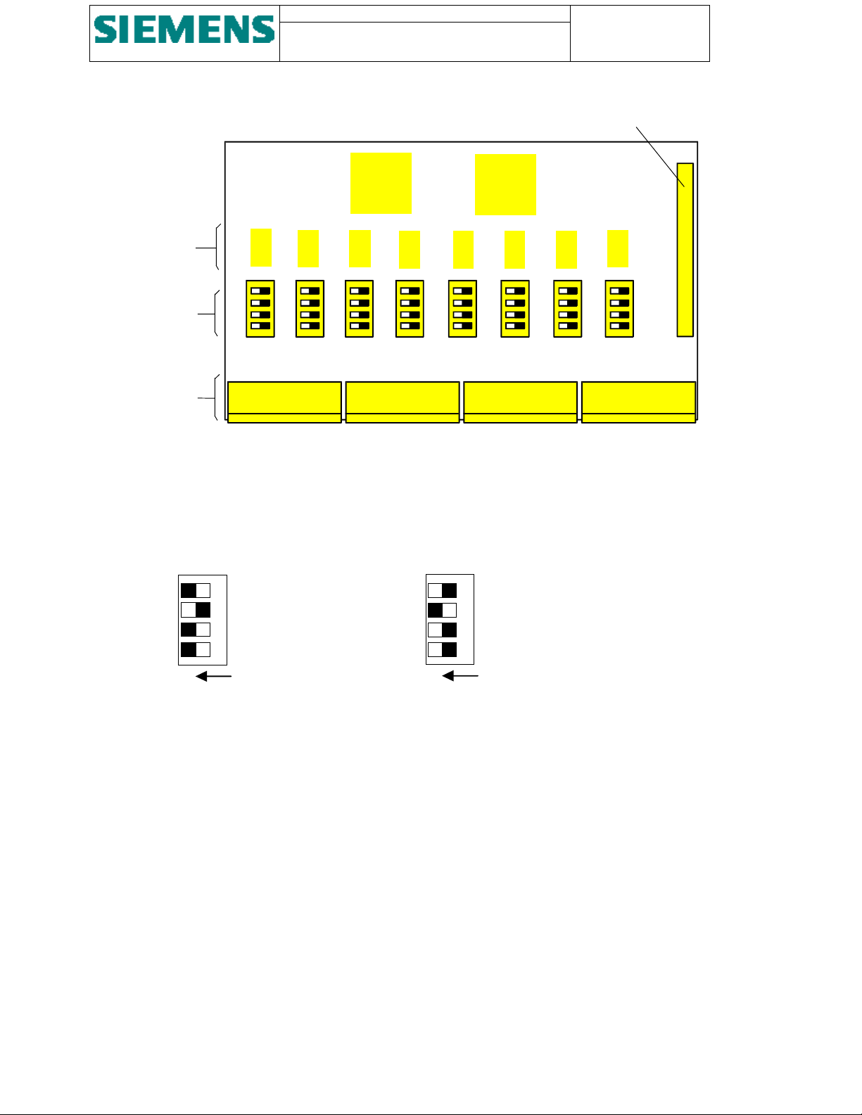
Resistance
r
3
network
Dipswitches for
setting of the
input rating
SU200 User manual
This document is confidential and is the property of Siemens AS. It may not
be copied, reproduced, or disclosed in any form without the express written
consent of Siemens AS. Offenders are liable to the payment of damages. All
rights are reserved in the event of the grant of patent or the registration
Page: 27 of 103
Version: 11
Date: 17.Oct 2002
Order no: AB03-Y200-A
Ribbon cable connecto
S200 S201 S202 S203 S204 S205 S206 S207 X5
-X41:
-X42:
-X43: -X44:
Base sockets for
plug connectors
Figure 12 - Layout of analogue input module
Each channel of the analogue measuring input can be configured individually as ±10V input or ±20mA input.
The setting is done via a DIP switch provided for each channel.
Figure 13 shows the appropriate combinations.
+/- 20mA
ON
2
1
+/- 10V
3
1
ON
Figure 13 - DIP switches for type of analogue input signal
Page 28
Page: 28 of 103
Version: 11
Date: 17.Oct 2002
Order no: AB03-Y200-A
SU200 User manual
This document is confidential and is the property of Siemens AS. It may not be
copied, reproduced, or disclosed in any form without the express written
consent of Siemens AS. Offenders are liable to the payment of damages. All
rights are reserved in the event of the grant of patent or the registration
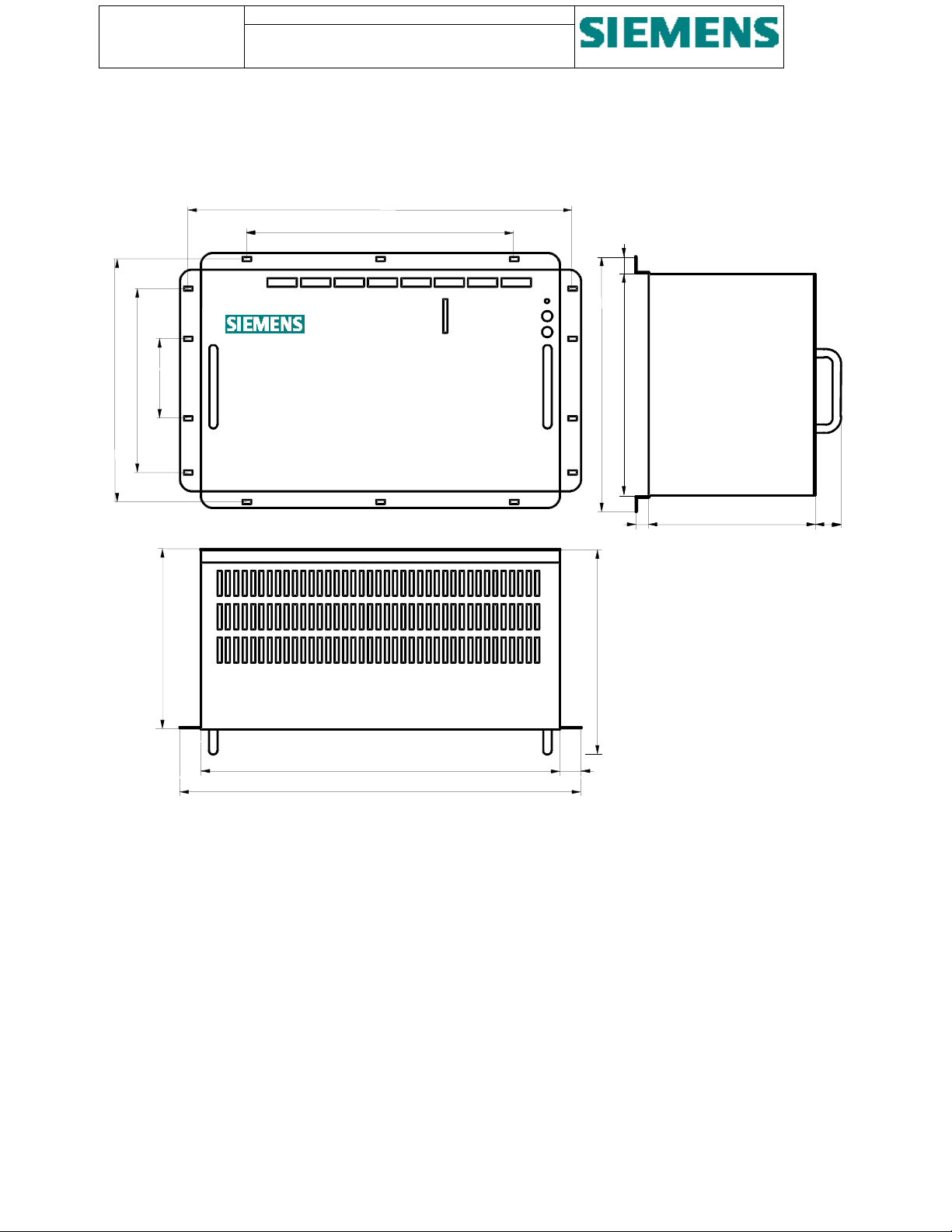
3.3. Dimensions
465
322
19
81 190 76
220
SU200
Front view
432
486
Top view
27
250
298
260
14
202
Side view
34
Figure 14 - Dimensions
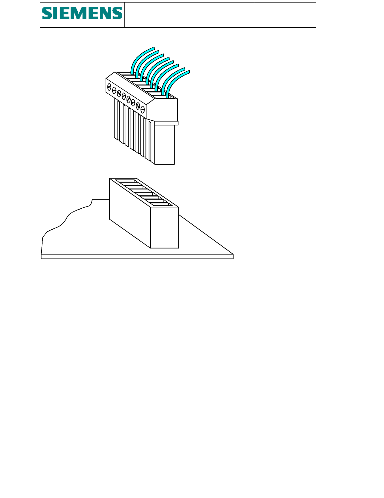
3.4. Connections
The connection of the external wires is done by way of standard plug-in connectors, consisting of plug connectors and
base sockets, which are fixed on the respective board.
Page 29
SU200 User manual
This document is confidential and is the property of Siemens AS. It may not
be copied, reproduced, or disclosed in any form without the express written
consent of Siemens AS. Offenders are liable to the payment of damages. All
rights are reserved in the event of the grant of patent or the registration
External wiring
Plug connector
Page: 29 of 103
Version: 11
Date: 17.Oct 2002
Order no: AB03-Y200-A
Base socket
Board
Figure 15 - Plug-and-socket connection of external wiring
The signal input is arranged with 9-pole plugs, for command output 6-pole plugs are provided. Thus, exchange of plug
connectors by mistake is prevented.
All plugs for digital input and output are designed with 4 mm
connectors with 2.5 mm
2
screw terminals are provided.
2
screw terminals. For the analogue input, 6-pole plug
Figure 16 shows the various plug connector versions with the associated internal circuitry.
Page 30
Page: 30 of 103
put
Version: 11
Date: 17.Oct 2002
Order no: AB03-Y200-A
Channel 1
Channel 2
Channel 3
Channel 4
Channel 5
Channel 6
Channel 7
Channel 8
SU200 User manual
This document is confidential and is the property of Siemens AS. It may not be
copied, reproduced, or disclosed in any form without the express written
consent of Siemens AS. Offenders are liable to the payment of damages. All
rights are reserved in the event of the grant of patent or the registration
-X11:
-X15:
1
Channel 1
Channel 2
2
3
4
5
6
7
8
9
-X21:
-X32:
1
2
3
4
5
6
Channel 1
Channel 2
9-pole plug-in connector for
digital input connection
10V /
20mA
10V /
20mA
6-pole plug-in connector for
analogue input connection
-X41:
-X44:
1
2
3
4
5
6
6-pole plug-in connector for
relay output connection
-
+
-
+
-
+
6-pole plug-in connector for
redundant power supply and
electrical time synchronization
in
-X2:
-X1:
-X7:
Figure 16 - Types of connecting plugs with internal circuitry
Page 31

SU200 User manual
This document is confidential and is the property of Siemens AS. It may not
be copied, reproduced, or disclosed in any form without the express written
consent of Siemens AS. Offenders are liable to the payment of damages. All
rights are reserved in the event of the grant of patent or the registration
Page: 31 of 103
Version: 11
Date: 17.Oct 2002
Order no: AB03-Y200-A
4. Method of operation
4.1. Operation principle
SU200 is equipped with powerful 16 bit microprocessors. This provides fully digital pre-processing of process data.
Process data are acquired at the field level via the digital and analogue inputs of SU200. The values are formatted into
telegrams and transmitted via a fieldbus link to the central control station.
Each recognised status change of the digital inputs is converted into a process message, marked with date and time with
1 ms. resolution, and written into a message buffer. These time-tagged process messages are together with analogue
values passed on to the central control station.
Control commands from the central control station are converted and provided in parallel form at the output circuitry of
SU200.
Each of the relay output channels is arranged with a feedback control circuit in order to monitor correct command
output.
4.2. Self-monitoring
All hardware and firmware functions of SU200 are continuously monitored by way of plausibility checks. If
irregularities are detected in hardware or firmware, a system message marked with date and time is written into the
message buffer.
The time-tagged system messages are immediately transmitted to the central control station as a common system
message.
Figure 20 shows the individual single system messages and the combination into the respective common system
message, which is then transmitted to the central control station. All single system messages can however be read from
the message buffer using SU200DIA application
Page 32

Page: 32 of 103
Version: 11
Date: 17.Oct 2002
Order no: AB03-Y200-A
SU200 User manual
This document is confidential and is the property of Siemens AS. It may not be
copied, reproduced, or disclosed in any form without the express written
consent of Siemens AS. Offenders are liable to the payment of damages. All
rights are reserved in the event of the grant of patent or the registration
Local
message
Description Logic to
common
Common
message
Description
message
S-101 Unit start-up = S-141 Unit start-up
S-102 Time synchronising trigger signal missing
S-104 Power supply #1 failure
≥
S-142 Device disturbed
S-105 Power supply #2 failure
S-114 Power supply #1 healthy
&
S-143 Device disturbance cleared
S-115 Power supply #2 healthy
S-116 Time synchronising trigger signal received
S-106 CPU-RAM failure
S-107 EEPROM failure
S-108 Watchdog failure
≥
S-144 Device faulty
S-109 Communications interface #1 internal failure
S-110 Communications interface #2 internal failure
S-113 Analogue input card faulty.
S-117 Special function: Programmable interlocking rule
program checksum failure
S-118 FLASH memory write failure
S-1…S-12 Output group 1…12 faulty
S-146 Local control mode actuated = S-146 Local control mode
actuated
S-147 Remote control mode actuated = S-147 Remote control mode
actuated
S-103 Message buffer overflow - 500 unsent messages
stored.
No transmission to higher
control level
S-111 Communications interface #1 out of service - No transmission to higher
control level
S-112 Communications interface #2 out of service - No transmission to higher
control level
Table 1 - System messages generated by the self-monitoring facility
If single master mode is programmed, system message S-111 respectively S-112 is not generated if the second
communications channel is out of service.
4.3. Redundancy
SU200 is designed for fieldbus communications in single master or dual master configuration, whereas single master
configuration may be utilised via any of the two interfaces.
The redundant communications interface enables SU200 to be integrated in a station control system in hot standby
mode.
Page 33

SU200 User manual
This document is confidential and is the property of Siemens AS. It may not
be copied, reproduced, or disclosed in any form without the express written
consent of Siemens AS. Offenders are liable to the payment of damages. All
rights are reserved in the event of the grant of patent or the registration
A hot standby configuration at the higher station control level is achieved with an active and a passive central control
station (master), representing a two-channel configuration with a dynamic 1-out-of-2 redundancy. Both central control
stations run in a parallel mode, each with a full update of the process image at any time.
If a hardware or firmware error is detected in the active central control station, immediate and bumpless transfer to the
hot standby (passive central control station) is executed by means of an automatic switchover system and the hot
standby becomes active control unit.
The switchover between master and hot standby is executed without any loss of information and the process is kept
going.
SU200 is designed to accept and process orders received from the active central control station only. If SU200
recognises a switchover of the two central control stations via a specific bit pattern in the received telegrams, the actual
output commands are frozen for 3 seconds.
After 3 seconds, new output orders from the central control station are accepted by SU200 only if one single active
central control station is recognised, in all other cases the command output is reset (command ending).
Page: 33 of 103
Version: 11
Date: 17.Oct 2002
Order no: AB03-Y200-A
4.4. Data transfer
4.4.1. Fieldbus
SU200 is designed for data interchange between station and field control level via a fieldbus.
For the open communications between the central control station (master) at the higher station control level and SU200
at the field control level, the PROFIBUS fieldbus is used.
PROFIBUS defines the technical and functional characteristics of a fieldbus and provides for extremely fast handling as
well as comprehensive interchange of process data.
PROFIBUS offers an extensive range of network components for electrical and optical transmission and combines
simple installation and service, good diagnostic facilities and an error-free transmission in an optimal manner.
4.4.2. Network configuration
With the use of star couplers, repeaters and/or optical link modules (OLM‘s) and optical link plugs (OLP‘s), the
PROFIBUS network can be configured individually in a in-line, ring or star topology and allows the linking of two-wire
(copper) and fibre optic transmission media.
4.4.3. Principle of operation
Data exchange on the PROFIBUS fieldbus runs in a programmed cycle using the principle of a master-slave system as
specified in European Norm EN 50 170.
Masters only may initiate requests for data, slaves may only respond to this requests.
4.4.4. Transmission media
SU200 is equipped with two ports for connection of an electrical transmission media and another two ports for
connection of an optical transmission media (redundant interface). Only one of the two communications interfaces
(electrical or optical) of SU200 can be in service at any time.
Page 34

Page: 34 of 103
Version: 11
Date: 17.Oct 2002
Order no: AB03-Y200-A
SU200 User manual
This document is confidential and is the property of Siemens AS. It may not be
copied, reproduced, or disclosed in any form without the express written
consent of Siemens AS. Offenders are liable to the payment of damages. All
rights are reserved in the event of the grant of patent or the registration
4.4.5. Electrical transmission media
• The electrical PROFIBUS fieldbus is arranged with 2-core (twisted pair) double-shielded cable.
• Transmission standard RS 485 is utilised.
• The RS 485 interface operates on voltage differences and is therefore less sensitive to interference than a voltage or
current interface.
• The maximum number of nodes of an electrical fieldbus is 32 per segment.
• By means of repeaters a two-wire network can be extended to 127 nodes.
• SU200 is suitable for transmission speed of up to 1.5 MBaud. In particular cases, transmission speed of up to
12 MBaud is possible.
4.4.6. Optical transmission media
The fibre optic network is set up with duplex fibre optic cables (glass or plastic) and is insensitive to electromagnetic
interference.
FO cables serve to transmit signals by means of electromagnetic waves in the region of optical frequencies. SU200
transmitter and receiver are suitable for transmission speed of up to 5 MBaud.
For communications between bus nodes, there is no discernible difference between the two-wire and fibre optic
technology.
4.5. Telegram structure
4.5.1. From SU200 to Master
For the data transmission from SU200 to the central control station (master), the telegram is structured with 32 bytes of
user data.
SU200 will automatically switch between transmission of various types of telegrams:
AI
enabled
(and not
faulty)
No No Process- and system-messages are transmitted once they are generated. After
No Yes If there are no process- or system-messages to transmit, SU200 will transmit kWh
kWh counter Transmission of messages
acknowledgement from the master, SU200 will repeat transmitting the telegram
until a new process- or system-message is generated.
counter values continuously.
When a new process- or system-message is generated, SU200 will continuously
transmit the system/process-message until it’s acknowledged, thus while waiting
for acknowledgement, kWh counter values are not transmitted.
Yes No If there are no process- or system-messages to transmit, SU200 will transmit
analogue values continuously.
When a new process- or system-message is generated, SU200 will transmit this
message for 2 out of 3 times until it’s acknowledged, thus while waiting for
acknowledgement; analogue values are transmitted in every third telegram.
Page 35

SU200 User manual
)
)
)
)
p
)
g
)
)
p
)
g
)
)
g
)
)
)
)
)
)
g
)
)
)
g
)
)
)
g
)
)
)
)
)
)
g
)
)
)
g
)
)
)
(
)
(
)
This document is confidential and is the property of Siemens AS. It may not
be copied, reproduced, or disclosed in any form without the express written
consent of Siemens AS. Offenders are liable to the payment of damages. All
rights are reserved in the event of the grant of patent or the registration
Page: 35 of 103
Version: 11
Date: 17.Oct 2002
Order no: AB03-Y200-A
Yes Yes If there are no process- or system-messages to transmit, SU200 will continuously
alternate between transmission of kWh counter values and analogue input values.
When a new process- or system-message is generated, SU200 will transmit this
message for 2 out of 3 times and analogue values in every third telegram until the
message is acknowledged.
N/A N/A Message transmission blocked (In local control mode)
As described in the above situations but as if SU200 has no process- or systemmessages to transmit
Table 2 - Transmission of various types of telegrams
Four different types of telegram structures are used for communications:
• Message telegram (consisting of process messages or system messages)
• Analogue value telegram
• General scan telegram
• kWh counter telegram
Figure 17 shows the principle arrangement of the different telegram structures.
Byte
Message telegram
1. Control #1
2. Control #2
3. Digital input 1 to 8
4. Digital input 9 to 16
5. Digital input 17 to 24
6. Digital input 25 to 32
7. Digital input 33 to 40
8. Signal identification (L
9. Signal identification (H)
10. Timestamp: days (L
11. Timestamp: days (H)
12. Timestamp: ms (LL
13. Timestamp: ms (LH)
14. Timestamp: ms (HL
15. Timestamp: ms (HH)
16. Signal identification (L
17. Signal identification (H)
18. Timestamp: days (L
19. Timestamp: days (H)
20. Timestamp: ms (LL
21. Timestamp: ms (LH)
22. Timestamp: ms (HL
23. Timestamp: ms (HH)
24. Signal identification (L
25. Signal identification (H)
26. Timestamp: days (L
27. Timestamp: days (H)
28. Timestamp: ms (LL
29. Timestamp: ms (LH)
30. Timestamp: ms (HL
31. Timestamp: ms (HH)
32. Control #2
1. message
2. message
3. message
General scan telegram
Control #1
Control #2 Control #2
Digital input 1 to 8
Digital input 9 to 16 Digital input 9 to 16
Digital input 17 to 24 Digital input 17 to 24
Digital input 25 to 32 Digital input 25 to 32
Digital input 33 to 40 Digital input 33 to 40
Timestamp: days (L
Timestamp: days (H) Analogue input #1 (H)
Timestam
: ms (LL
Timestamp: ms (LH) Analogue input #2 (H)
Timestam
: ms (HL
Timestamp: ms (HH) Analogue input #3 (H)
Si
nal identification (L
Signal identification (H) Analogue input #4 (H)
Signal identification (L
Signal identification (H) Analogue input #5 (H)
Si
nal identification (L
Signal identification (H) Analogue input #6 (H)
Si
nal identification (L
Signal identification (H) Analogue input #7 (H)
Si
nal identification (L
Signal identification (H) Analogue input #8 (H)
Signal identification (L
Signal identification (H) (not used)
Si
nal identification (L
Signal identification (H) (not used)
Si
nal identification (L
Signal identification (H) (not used)
not used
(not used) (not used)
Control #2
common time
1. message
2. message
3. message
4. message
5. message
6. message
7. message
8. message
Analogue value telegram
Control #1
Digital input 1 to 8
Analogue input #1 (L
Analo
ue input #2 (L
Analo
ue input #3 (L
Analogue input #4 (L
Analogue input #5 (L
Analogue input #6 (L
Analogue input #7 (L
Analogue input #8 (L
(not used
(not used
(not used
not used
Control #2
Page 36

Page: 36 of 103
Version: 11
Date: 17.Oct 2002
Order no: AB03-Y200-A
SU200 User manual
This document is confidential and is the property of Siemens AS. It may not be
copied, reproduced, or disclosed in any form without the express written
consent of Siemens AS. Offenders are liable to the payment of damages. All
rights are reserved in the event of the grant of patent or the registration
Figure 17 - Structure of telegrams from SU200 to master
Page 37

SU200 User manual
)
)
)
)
)
)
)
)
)
This document is confidential and is the property of Siemens AS. It may not
be copied, reproduced, or disclosed in any form without the express written
consent of Siemens AS. Offenders are liable to the payment of damages. All
rights are reserved in the event of the grant of patent or the registration
Page: 37 of 103
Version: 11
Date: 17.Oct 2002
Order no: AB03-Y200-A
Byte
kWh counter telegram
1. Control #1
2. Control #2
3. Digital input 1 to 8
4. Digital input 9 to 16
5. Digital input 17 to 24
6. Digital input 25 to 32
7. Digital input 33 to 40
8. kWh counter # 1(L
9. kWh counter # 1(H)
10. kWh counter # 2(L
11. kWh counter # 2(H)
12. kWh counter #3 (L
13. kWh counter #3 (H)
14. kWh counter #4 (L
15. kWh counter #4 (H)
16. kWh counter #5 (L
17. kWh counter #5 (H)
18. kWh counter #6 (L
19. kWh counter #6 (H)
20. kWh counter #7 (L
21. kWh counter #7 (H)
22. kWh counter #8 (L
23. kWh counter #8 (H)
24. kWh counter #9 (L
25. kWh counter #9 (H)
26. kWh counter #10 (L)
27. kWh counter #10 (H)
28. kWh counter #11 (L)
29. kWh counter #11 (H)
30. kWh counter #12 (L)
31. kWh counter #12 (H)
32. Control #2
(L) Low-byte of the word (16 bit code)
(H) High-byte of the word
(LL) Low-byte of the lower order word of the
double-word (32 bit code)
(LH) High-byte of the lower order word of the
double-word
(HL) Low-byte of the higher order word of the
double-word
(HH) High-byte of the higher order word of the
double-word
Figure 18 - Continued: Structure of telegrams from
SU200 to master
Two control bytes and the actual state of all digital inputs are incorporated in all telegram types and is
permanently updated and transmitted.
The message telegram consists of control bits incorporated into control bytes #1 and #2, the actual state of all
digital inputs and a maximum of three messages. The input status is permanently updated and transmitted.
Each message consists of its signal identification (double-word / two bytes) and the time of acquisition in a
six byte code, consisting of the days since 01.01.1984 and the milliseconds after the last full day from
00.00.00
h
onward.
The analogue value telegram consists of the control bits incorporated into control bytes #1 and #2, the actual
state of all digital inputs and the actual measured values of the 8 channels. The input status and the analogue
values are permanently updated and transmitted.
The kWh counter telegram consists of the control bits incorporated into control bytes #1 and #2, the actual
state of all digital inputs and the actual kWh counter inputs of the 12 kWh counter channels. The input status
and the kWh counter values are permanently updated and transmitted.
The general scan telegram is only transmitted after a request from the central control station and consists
likewise of control bits incorporated into control bytes #1 and #2 and the actual state of all digital inputs. In
contrast to the message telegram, the general scan telegram consists of eight messages with only one
common scan time information.
Page 38

Page: 38 of 103
)
)
Version: 11
Date: 17.Oct 2002
Order no: AB03-Y200-A
SU200 User manual
This document is confidential and is the property of Siemens AS. It may not be
copied, reproduced, or disclosed in any form without the express written
consent of Siemens AS. Offenders are liable to the payment of damages. All
rights are reserved in the event of the grant of patent or the registration
4.5.2. From master to SU200
For the data reception from the central control station, the telegram is structured with 12 bytes of user data.
Figure 19 shows the principle arrangement of the telegram.
Byte
1. Control #1
2. Control #2
3. Relay output 1 to 8
4. Relay output 9 to 16
5. Relay output 27 to 24
6. Setpoint-time: days (L
7. Setpoint-time: days (H)
8. Setpoint-time: ms (LL)
9. Setpoint-time: ms (LH)
10. Setpoint-time: ms (HL)
11. Setpoint-time: ms (HH)
12. (not used
Figure 19 - Structure of telegrams from master to SU200
(L) Low-byte of the word (16-bit code)
(H) High-byte of the word
(LL) Low-byte of the lower order word of the double-word (32 bit code)
(LH) High-byte of the lower order word of the double-word
(HL) Low-byte of the higher order word of the double-word
(HH) High-byte of the higher order word of the double-word
The telegram consists of control bits incorporated into control bytes #1 and #2, output orders for the 24
output channels and a time information in a six byte code, consisting of the days since 01.01.1984 and the
milliseconds after the last full day from 00.00.00
h
onward.
The time information serves as an advanced lead-time for the initial setting of the internal clock of SU200
(see chapter Clock control).
4.6. Communications control
Communication between the central control stations and SU200 is controlled and co-ordinated by way of
status-bits in the telegrams.
4.6.1. From SU200 to master
Control bytes #1 and #2 of the telegrams from SU200 to the master serve for communications control.
Page 39

SU200 User manual
This document is confidential and is the property of Siemens AS. It may not
be copied, reproduced, or disclosed in any form without the express written
consent of Siemens AS. Offenders are liable to the payment of damages. All
rights are reserved in the event of the grant of patent or the registration
4.6.1.1. Control byte #1
Bit87654321
XXXX1/00/11/00/1
Page: 39 of 103
Version: 11
Date: 17.Oct 2002
Order no: AB03-Y200-A
Togglebits enabling master to monitor the communication.
These bits are permanently toggled by SU200 between the
bitpatterns "01" and "10".
The bitpattern is always equal to the value of the received
togglebits in control byte 1 in the telegram from the master to
SU200 (as long as this bitpattern is legal).
Indication of current active/passive central control station.
10 Indicates communication with the active central control
station (master)
01 Indicates communication with the passive central control
station (hot standby)
Other bitpatterns are never transmitted by SU200.
Message block number.
The bitpattern is set to "0000" unless the telegram contains process
messages, system messages or general scan messages which has
not yet been acknowledged by the master.
Every time a new message block is transmitted, the bitpattern is
incremented by 1, wrapping around from 15 to 1 if necessary.
Once the message block is acknowledged by the master, the
message block number is set to "0000" unless there are more
messages to transmit.
In telegrams containing analogue input value or kWh counter
values, the bitpattern is set to "0000".
Figure 20 - Arrangement of control byte #1 in telegram from SU200 to master
Page 40

Page: 40 of 103
Version: 11
Date: 17.Oct 2002
Order no: AB03-Y200-A
SU200 User manual
This document is confidential and is the property of Siemens AS. It may not be
copied, reproduced, or disclosed in any form without the express written
consent of Siemens AS. Offenders are liable to the payment of damages. All
rights are reserved in the event of the grant of patent or the registration
4.6.1.2. Control byte #2
Bit87654321
X0 XXXXXX
3-bit frame-type:
000 Telegram contains process messages. If the message block
number in control byte 1 is non-zero, the master has not yet
acknowledged these messages.
001 Telegram contains general scan messages If the message block
number in control byte 1 is non-zero, these messages have not
yet been acknowledged by the master.
010 Telegram contains system messages If the message block
number in control byte 1 is non-zero, these messages have not
yet been acknowledged by the master.
100 Telegram contains analogue values.
101 Telegram contains kWh counter values.
110 (not used)
111 (not used)
1=Device faulty, as defined in system message 144.
1=The message buffer contains process- or system-messages which
hasn't yet been transmitted or acknowledged.
Local control mode is active (as signalled by system message 146).
(not used)
This bit is toggled by SU200 in every transmitted telegram.
Figure 21 - Arrangement of control byte #2 in telegram from SU200 to master
Page 41

SU200 User manual
This document is confidential and is the property of Siemens AS. It may not
be copied, reproduced, or disclosed in any form without the express written
consent of Siemens AS. Offenders are liable to the payment of damages. All
rights are reserved in the event of the grant of patent or the registration
Page: 41 of 103
Version: 11
Date: 17.Oct 2002
Order no: AB03-Y200-A
4.6.2. From master to SU200
Control bytes #1 and #2 of the telegrams from the master to SU200 serve for communications control.
4.6.2.1. Control byte #1
Bit87654321
XXXX1/00/11/00/1
Togglebits enabling SU200 to monitor the communication.
These bits should be permanently toggled by the central control
stations between the bitpatterns "01" and "10".
SU200 will assume that the connection to the central control station
is interrupted if no toggling occurs within 4 seconds.
See chapter Figure 23 - Arrangement of control byte #2 in telegram
from master to SU200
Communications monitoring.
The combination "00" or "11" is illegal. Illegal telegrams are
ignored by SU200.
Request for active/passive central control station.
10 The central control station wants to be active.
01 The central control station wants to be passive.
The combination "00" or "11" is illegal. Illegal telegrams are
ignored by SU200.
See chapter Redundancy.
If both central control stations (in dual master mode) want to be
active, this is interpreted by SU200, as both units want to be passive.
Acknowledgement of a message block.
This bitpattern should be set-up by the master in order to
acknowledge the receipt of a message block.
When SU200 transmits a message block with messages, which
hasn't yet been acknowledged, a new message block number is
transmitted. The master signals the receipt of the message block by
returning the received message block number in these bits.
This bitpattern is ignored in telegrams from passive central control
stations.
Figure 22 - Arrangement of control byte #1 in telegram from master to SU200
Page 42

Page: 42 of 103
Version: 11
Date: 17.Oct 2002
Order no: AB03-Y200-A
SU200 User manual
This document is confidential and is the property of Siemens AS. It may not be
copied, reproduced, or disclosed in any form without the express written
consent of Siemens AS. Offenders are liable to the payment of damages. All
rights are reserved in the event of the grant of patent or the registration
4.6.2.2. Control byte #2
Bit87654321
0000000X
1=The master wants to activate a general scan. This bit is ignored
in telegrams from passive central control stations.
(not used)
Figure 23 - Arrangement of control byte #2 in telegram from master to SU200
4.6.3. Communications monitoring
Communications monitoring is done on both sides of the fieldbus link. In addition to the data transfer
monitoring carried out by the PROFIBUS master, each SU200 is permanently monitoring the data transfer
link via the toggle bits in control byte 1 received from the master.
The bit-patterns "00" or "11" are illegal. Illegal telegrams are ignored by SU200.
If a telegram with a new bitpattern in the togglebits isn’t received by SU200 every four second, a
communications error is recognised and the actual command outputs are reset.
As soon as a new valid telegram is received, communications is considered as healthy again.
4.7. Cyclic buffer
SU200 unit is equipped with a message buffer for storage of up to 500 process messages and 50 system
messages The buffer is designed in a write-over mode, i.e. in case of a buffer overflow, the ”oldest“ stored
message is overwritten.
Messages, which have been transmitted to the central control station, are kept stored and can still be read
using the SU200DIA application
Transmitted messages are marked as acknowledged as soon as the central control station returns the message
telegram number, see chapter From master to SU200.
4.8. Clock control
The date and time information for time tagging of messages is provided via the internal clock of SU200. The
internal clock is designed with an accuracy of 10
After start-up of SU200, the internal clock starts with 00:00:000
with the date 1984.01.01.
-5
(max. 36 ms/hour)
h
and time tagging of messages commences
As soon as the communications link with the active master is in service, the internal clock of SU200 is set
provisionally with the lead time information received via the first telegram from the central control station.
Subsequently, the time mark of messages, which have been written into the message puffer prior to the
reception of the first telegram, is corrected relatively to the time difference.
The time information sent by the central control station is given a few seconds ahead of the actual time and
serves as a lead-time for the setting of the internal clock via an external trigger signal.
For the time synchronisation of the internal clock, an optical and electrical trigger signal input is provided.
The unit is designed to receive a time synchronising impulse (at least 100µs) from an external master clock
Page 43

SU200 User manual
This document is confidential and is the property of Siemens AS. It may not
be copied, reproduced, or disclosed in any form without the express written
consent of Siemens AS. Offenders are liable to the payment of damages. All
rights are reserved in the event of the grant of patent or the registration
Page: 43 of 103
Version: 11
Date: 17.Oct 2002
Order no: AB03-Y200-A
each minute, whereas the synchronisation is initiated by the rising edge of the signal.
In output mode of the LED indication, LED #39 mirrors the state of the time synchronising input by way of
lighting up as long as an optical or electrical signal is applied
Page 44

Page: 44 of 103
g
Version: 11
Date: 17.Oct 2002
Order no: AB03-Y200-A
SU200 User manual
This document is confidential and is the property of Siemens AS. It may not be
copied, reproduced, or disclosed in any form without the express written
consent of Siemens AS. Offenders are liable to the payment of damages. All
rights are reserved in the event of the grant of patent or the registration
5. Controls and displays
The following control and indication elements are provided on SU200 unit:
LED’s indicating the actual state of each
input or output channel
345
12
SU200
SU200
SU200SU200
678 9101112 13
LED’s indicating healthy operation of the unit
14 15
19 20
16 17 18
OPERATION
POWER SUPPLY
INTERFACE 1
INTERFACE 2
21 22
24 25 26 27 28 29 30 31
23
32 3334353637
RESET
LED TEST
DISPLAY MODE
Push-buttons
38 39 40
SERVICE
LED`s indicating healthy communications on
the two fieldbus channels
Serial interface for parameterization,
dia
nostics and local control
Figure 24 - Buttons and LED’s
5.1. LED display
The green LED named OPERATION indicates the operational status of the device.
Light Indication
Steady light Auxiliary power is switched on and SU200 is properly functioning
1 Hz flashing light Internal failure, see chapter Self-monitoring.
Dark Auxiliary power off
Table 3 - OPERATION LED
The green LED named POWER SUPPLY indicates the status of the auxiliary power supply.
Light Indication
Page 45

SU200 User manual
This document is confidential and is the property of Siemens AS. It may not
be copied, reproduced, or disclosed in any form without the express written
consent of Siemens AS. Offenders are liable to the payment of damages. All
rights are reserved in the event of the grant of patent or the registration
Page: 45 of 103
Version: 11
Date: 17.Oct 2002
Order no: AB03-Y200-A
Steady light Both power supply modules are properly functioning
½ Hz Flashing light Failure in power supply #1
1 Hz flashing light Failure in power supply #2
5 Hz Flashing light Internal monitoring of power supplies faulty or both power supplies defective
Table 4 - POWER SUPPLY LED
Power supply monitoring of SU200 is carried out continuously by way of comparing the output voltage level
of both power supply modules with an internally set low voltage limit.
Note: The unit does not contain a specific on/off switch for the auxiliary power supply. Therefore SU200
is in operation as soon as an appropriate voltage is applied to one of the two power supply modules.
The two green LED‘s named INTERFACE 1 and INTERFACE 2 indicate the operational status of the
redundant PROFIBUS interface.
Light Indication
Steady light Communications interface healthy and in service
Dark Communications interface out of service or disturbed
1 Hz flashing light Transmission of messages blocked, SU200 is under local control by means of a connected PC
and transmissions of messages are suppressed.
Table 5 - INTERFACE LED’s
Forty green LED’s at the top of SU200 indicate the signal status of each input channel (basic setting),
whereas 8 openings on the cover plate are showing five LED‘s in each case.
A set LED indicates an initiated/energised input channel (if positive signal logic is set, see chapter
Parameterisation).
By clicking the button DISPLAY MODE, the display changes to status indication of each command output
channel. If command output status is selected, LED #40 is blinking (1 Hz period).
Since all output channels are monitored for correct command output in groups of two channels by way of
feedback circuits, always two channels are blocked in case of one channel is faulty.
Page 46

Page: 46 of 103
Version: 11
Date: 17.Oct 2002
Order no: AB03-Y200-A
SU200 User manual
This document is confidential and is the property of Siemens AS. It may not be
copied, reproduced, or disclosed in any form without the express written
consent of Siemens AS. Offenders are liable to the payment of damages. All
rights are reserved in the event of the grant of patent or the registration
LED input mode
1 2 3 4 5 6 7 8 9 10 1112131415 161718 1920 2122232425 262728 2930 31 32 33 3435 36373839 40
LED #2 shows the status of
input channel #40
digital input channel #2
LED #1 shows the status of
digital input channel #1
LED output mode
1 2 3 4 5 6 7 8 9 10 111213 1415 161718 1920 212223 2425 262728 2930 313233 34 35 3637383940
LED #3 and #4 show the status of relay
output group #2 with output
channels #3 and #4
LED #1 and #2 show the status of relay output
group #1 with output channels #1 and 2#
LED #23 and #24 show the status of relay group #12
with output channels #23 and #24
LED #40 shows the status of digital
LED #32 set when simulation of digital input signals is
LED #33 lit when local control active
LED # 34 lit when messages in the buffer
LED # 35 and #36 indicates wanted master
00=No master, 01=Channel#1, 10=Channel#2
LED # 37 and #38 indicates current master
00=No master, 01=Channel #1, 10=Channel #2
LED #39 lit on active time synch. input signal
Flashing LED #40 indicates output mode
Figure 25 - Status LED's
active
Page 47

SU200 User manual
This document is confidential and is the property of Siemens AS. It may not
be copied, reproduced, or disclosed in any form without the express written
consent of Siemens AS. Offenders are liable to the payment of damages. All
rights are reserved in the event of the grant of patent or the registration
Page: 47 of 103
Version: 11
Date: 17.Oct 2002
Order no: AB03-Y200-A
5.2. Buttons
RESET button
Clicking the RESET button initiates a hardware reset. This causes SU200 unit to perform a complete restart.
During restart, all LED‘s are lighting up for a short moment.
The RESET button should only be pressed for the purpose of clearing faults.
LED TEST button
When this button is pressed, a firmware test is carried out and all the LED‘s are switched on for the time of
clicking the button. This indicates that SU200 is operating properly.
DISPLAY MODE button
With this button, a changeover between digital input status indication and command output status indication
is possible. LED #40 will flash while command output status is displayed,
Boot mode
If both the LED TEST push button and the DISPLAY MODE button are pressed while a reset/power-up is
performed, all parameters are set to the factory-set values. These values are described in chapter
Parameterisation.
Firmware download mode
If the DISPLAY MODE button (only) is pressed while a reset/power-up is performed, the system enters a
state in which new firmware may be downloaded. Use the firmware tool with checkbox
marked.
5.3. Serial interfaces
Service channel interface
A serial channel (V.24 / V.28, RS-232, 9-pins SUB-D) is provided for parameterisation, diagnostics and local
control.
Use a null-modem cable where pins 2,3 and 7 is connected directly from the PC to SU200.
A DIP switch is provided at the underside of the CPU module and serves for the configuration of this serial
channel. The DIP switch is factory-set to V.24 / V.28 transmission standard (RS-232).
Download channel interface
A serial channel (V.24 / V.28, RS-232, 9-pins SUB-D) is provided for downloading of new firmware and
firmware access.
Page 48

Page: 48 of 103
Version: 11
Date: 17.Oct 2002
Order no: AB03-Y200-A
SU200 User manual
This document is confidential and is the property of Siemens AS. It may not be
copied, reproduced, or disclosed in any form without the express written
consent of Siemens AS. Offenders are liable to the payment of damages. All
rights are reserved in the event of the grant of patent or the registration
6. SU200DIA
SU200DIA application enables the user to set read/write operational parameters and read process data in
order to carry out local diagnosis or fault tracing.
Figure 26 shows the start-up window of SU200DIA.
Figure 26 - Start-up window of SU200DIA
Button Function
Connect Click this button if the PC is connected to a SU200. Parameters and messages will be read from
SU200 and shown in main window. The communication port can be selected prior to attempting
communicate with SU200.
Work Offline No data are read from SU200, the main window will show default parameters. Parameter-files can be
opened and viewed. The parameters can be read from SU200 at any later point.
The version of SU200DIA as well as it’s communication component (su200com.dll) are shown. The user
may select to not show the start-up window the next time SU200DIA is started. This setting is stored in the
Startup key in the file consi.ini file in the Windows directory.
Figure 27 shows the main window of SU200.
Page 49

SU200 User manual
This document is confidential and is the property of Siemens AS. It may not
be copied, reproduced, or disclosed in any form without the express written
consent of Siemens AS. Offenders are liable to the payment of damages. All
rights are reserved in the event of the grant of patent or the registration
Page: 49 of 103
Version: 11
Date: 17.Oct 2002
Order no: AB03-Y200-A
Figure 27 - Main window of SU200DIA
Parameters and diagnostics are read from SU200 clicking the Fetch button. If Fetch continuously checkbox is
checked, data are read continuously until cancelled by user.
All parameters can be set to their default values clicking the Default button.
Parameters are transferred to SU200 clicking the Apply button.
Parameters may be saved in parameter files. The files can be opened and displayed.
The content of the Message list and Digital inputs may be saved in a message-file. Message-files can be
opened and viewed.
The Analogue inputs list is only updated when data are read from SU200. This values are not saved in a file.
A Tools menu gives access to the following functions:
• A mode enabling local control of the relay outputs
• Simulation of the signal level of all 40 digital inputs
• Programming of rules for interlocking of commands
• View/modify impulse counter values
• Configuring fail-safe state
• Configure internal system parameters
• Selection of communication port on PC
• Firmware tool for low-level fault-tracing and downloading of new firmware
6.1. Parameterisation
The following operation parameters can be set in SU200:
• PROFIBUS address
• Master mode, single master or dual master configuration
• Enable/disable analogue input
• Signal ID of individual digital inputs, necessary for data logging and data distribution at the central
control stations
• LED mode; how digital inputs are indicated on the LED’s
• The normal signal level of the digital inputs, high- or low signal level on alarm
Page 50

Page: 50 of 103
Version: 11
Date: 17.Oct 2002
Order no: AB03-Y200-A
SU200 User manual
This document is confidential and is the property of Siemens AS. It may not be
copied, reproduced, or disclosed in any form without the express written
consent of Siemens AS. Offenders are liable to the payment of damages. All
rights are reserved in the event of the grant of patent or the registration
• Type of digital input; normal (for alarm) or impulse counter
• Timing for message generation
6.1.1. PROFIBUS address
Every SU200 unit has a PROFIBUS address that is unique on the bus.
A value in the range from 3 to 125 is allowed. The station numbers 1 and 2 are reserved for central control
stations (masters).
SU200 will instantly accept the new station address when the value is changed (not only at power-up).
6.1.2. Master mode
SU200 allows multi-master configuration with central control stations. The following modes are applicable:
Mode Function
Dual masters SU200 will communicate on and monitor both fieldbus links in a redundant mode.
Single master 1 SU200 unit will communicate on and monitor fieldbus link #1 only.
Single master 2 SU200 unit will communicate on and monitor fieldbus link #2 only.
Table 6 - Setting master mode in SU200DIA
6.1.3. Enable analogue inputs
If analogue input is disabled, analogue input values are not acquired/transmitted to the central control station
nor displayed in SU200DIA application.
Page 51

SU200 User manual
This document is confidential and is the property of Siemens AS. It may not
be copied, reproduced, or disclosed in any form without the express written
consent of Siemens AS. Offenders are liable to the payment of damages. All
rights are reserved in the event of the grant of patent or the registration
Page: 51 of 103
Version: 11
Date: 17.Oct 2002
Order no: AB03-Y200-A
6.1.4. Signal ID
Each of the digital inputs has a signal ID, which is unique in the entire control system and is pre-condition for
a proper processing and distribution of signals.
The range of the signal ID is 0 to 32767.
If the signal ID is set to 0, the signal status of the respective input channel is reported as normal, but no
message is generated by SU200. However, if a general scan telegram is transmitted to SU200, the signal
status of all channels is reported independent on whether the signal identification is 0 or any other number.
Each of the digital inputs of SU200 unit should have a unique ID (exception: ID number 0 may be specified
for several channels).
6.1.5. LED
A LED mode may be specified for each of the digital inputs.
If Follow mode is selected, the LED will continuously indicate the current alarm status or the physical
input signal status (depending on the setting of the Physical signal level on LED’s parameter).
If Storage mode is checked, the LED indication of the digital input is stored. This applies both for
indication of alarm-status or physical input signal. The LED will remain lit until the LED TEST button is
pressed.
If Physical signal level on LED’s is unchecked, SU200 will indicate alarms on the LED’s. Since both
positive and negative logic may be applied to digital inputs, a lit LED may not necessary indicate a high
signal on the input.
If Physical signal level on LED’s l is checked, SU200 will indicate physical signal levels on the LED’s. A
high signal on the input will cause the corresponding LED to light even if negative signal logic has been
applied.
The Physical signal level on LED’s parameter is common of all digital inputs, it can not be programmed
individually on a per-channel basis.
Physical signal Programmed setting
of Logic
Programmed setting
of Physical signal
LED status
level on LED’s
Low Positive - Off
1
Low Negative Off On
Low Negative On Off
1
High Positive - On
High Negative Off On
High Negative On Off
1:
If Storage mode is selected, a lit LED will not be switched off before LED TEST is pressed.
1
Page 52

Page: 52 of 103
Version: 11
Date: 17.Oct 2002
Order no: AB03-Y200-A
SU200 User manual
This document is confidential and is the property of Siemens AS. It may not be
copied, reproduced, or disclosed in any form without the express written
consent of Siemens AS. Offenders are liable to the payment of damages. All
rights are reserved in the event of the grant of patent or the registration
6.1.6. Logic
For each of the digital inputs, the user may specify the normal signal level.
If positive logic is checked, a high signal indicates an alarm condition.
If negative logic is checked, a low signal indicates an alarm condition.
6.1.7. Mode
A mode can be set for each of the digital inputs:
Normal mode.
The digital input is an impulse counter. No signal-alarm is generated from the digital input. The logic
level parameter does not apply. The LED will be continuously switched off. Read more about impulse
counters in chapter 6.3.4.
6.1.8. Timing
The user may define a Dead time and a Filter time for each of the digital inputs. A common time unit for
both time values can be selected in the Unit control.
Both time values serve as defined criteria’s for the generation of process messages, the digital input status
that is permanently transmitted to the control station is independent of this filtering.
The time values may be set in the range of 1 to 250 of the selected time unit. The time unit may be set to
1ms. , 10 ms., 1 sec. or 10 sec. Thus a time range from 1 ms. to 2550 seconds may be selected.
Signal status changes
from LOW to HIGH
Input signal
Status change acceptation
Dead time
Filter time
Figure 28 - Dead- and filter time of digital inputs
The dead time is specified in order to give the signal time to settle after a status change of a digital input.
Changes in the signal status during this time are not recognised.
If the signal level does not change during the specified filter time, the new signal status is accepted for the
generation of a process message.
The dead- and filter-time applies to signal transitions in both directions, from high to low level and from low
Page 53

SU200 User manual
This document is confidential and is the property of Siemens AS. It may not
be copied, reproduced, or disclosed in any form without the express written
consent of Siemens AS. Offenders are liable to the payment of damages. All
rights are reserved in the event of the grant of patent or the registration
Page: 53 of 103
Version: 11
Date: 17.Oct 2002
Order no: AB03-Y200-A
to high level.
6.1.9. Default parameter values
The default parameter values are factory-set. This values can be set as describe din chapter 5.2 or by clicking
the Default button and then the Apply button.
Parameter Value
PROFIBUS address 10
Analogue input enabled Yes
Signal ID 1 up to 40
Logic Positive
LED Follow mode.
Physical signal level on LED’s = 0
Physical signal level on LED’s No
Mode Normal
Deadtime 10 ms.
Filtertime 50 ms.
Master mode Dual master
Table 7 - Default parameter values
6.1.10. Managing parameter files
Parameters can be stored in parameter files. The files can be opened and viewed. The files have the extension
PAR.
The Parameters menu consists of the following items:
Menu Function
Open Opens and displays a parameter-file. No messages or input statuses will be displayed since this data are not
stored in the parameter-file. The full path of the file is displayed in the title line of the main window.
Save Saves the shown parameters on the currently selected parameter-file. If no parameter-file has been opened,
the user is prompted for a filename. The extension PAR is automatically added to the filename.
Save as.. Allows the user to save the shown parameters in a new file or another file than the file indicated in the title
of the main window
Table 8 - Parameter menu in SU200DIA
Page 54

Page: 54 of 103
Version: 11
Date: 17.Oct 2002
Order no: AB03-Y200-A
SU200 User manual
This document is confidential and is the property of Siemens AS. It may not be
copied, reproduced, or disclosed in any form without the express written
consent of Siemens AS. Offenders are liable to the payment of damages. All
rights are reserved in the event of the grant of patent or the registration
6.2. Diagnostics
Diagnostics can be read from SU200 clicking the Fetch button.
All messages checked: Fetch all messages from SU200 including those sent to the PROFIBUS DP
masters
All messages unchecked: Fetch only messages not yet sent to the PROFIBUS DP masters (e.g. if no
active PROFIBUS DP master is present)
The following diagnostics are available:
• Version of built-in firmware.
• Date and time in SU200.
• Analogue input values
• Status indication of all digital inputs.
• Process messages, which are written into the message buffer consisting of signal ID, date and time of
recognition and signal stage.
• System messages written into the message buffer consists of signal ID, date and time of recognition.
The message list may be stored in a file and later opened again, see chapter Managing message files. If the
message list displays messages read from a file, the name of the file will be displayed on-screen below the
message list.
6.2.1. Firmware version
Figure 29 - Firmware version in SU200DIA
The version of the built-in firmware of SU200 is shown when data are read from SU200.
6.2.2. Date and time
Figure 30 - Date and time in SU200DIA
The date and time in SU200 is displayed when data are read.
Following a power-up, the date/time in SU200 is set to 1. Jan. 1984. The date and time is modified when the
first telegram is received from the central control station. Subsequent changes of the date and time are only
performed when the time sync signal is raised.
Page 55

SU200 User manual
This document is confidential and is the property of Siemens AS. It may not
be copied, reproduced, or disclosed in any form without the express written
consent of Siemens AS. Offenders are liable to the payment of damages. All
rights are reserved in the event of the grant of patent or the registration
Page: 55 of 103
Version: 11
Date: 17.Oct 2002
Order no: AB03-Y200-A
In order to test SU200 without having a connection to a central control station, the date and time can be set
from SU200DIA. Check checkbox Set date/time and press the Apply button. This will set the date and time in
SU200 equal to the date and time in the PC.
The date and time is also stored in the parameter files. When a parameter file is opened, the date and time
when the parameters were read from SU200 is displayed.
6.2.3. Message list
Figure 31 - Message list in SU200DIA
The messages are sorted by time of generation; the newest message is displayed in the beginning of the table.
For each message, the following information is displayed:
• Signal ID of process messages: specified by the user
• Signal ID of system messages: internally fixed (see chapter Self-monitoring)
• Date (year, month and day) and time (hours, min, sec, and ms.) of signal recognition
• Signal stage of messages in the column labelled +/-:
+ indicates raised process signal (coming)
- indicates for process cleared signal (going)
Sys indicates a system message
Page 56

Page: 56 of 103
Version: 11
Date: 17.Oct 2002
Order no: AB03-Y200-A
SU200 User manual
This document is confidential and is the property of Siemens AS. It may not be
copied, reproduced, or disclosed in any form without the express written
consent of Siemens AS. Offenders are liable to the payment of damages. All
rights are reserved in the event of the grant of patent or the registration
6.2.4. Digital inputs
Figure 32 - Digital inputs in SU200DIA
The state of each of the digital inputs is displayed as a “1” or a “0” indicating the logical signal level. This
logical signal level is equal to the physical signal level unless negative logic has been applied.
6.2.5. Analogue inputs
Figure 33 - Analogue inputs in SU200DIA
The read measured analogue input values are displayed as a percentage value for each channel. The nominal
input value (± 10V or ± 20mA) is converted into ± 200%.
Analogue inputs are not displayed unless they have been enabled.
6.2.6. Managing message files
Messages and digital input status can be stored in message files. The files can be opened and viewed. The
files have the extension ALM.
Page 57

SU200 User manual
This document is confidential and is the property of Siemens AS. It may not
be copied, reproduced, or disclosed in any form without the express written
consent of Siemens AS. Offenders are liable to the payment of damages. All
rights are reserved in the event of the grant of patent or the registration
Page: 57 of 103
Version: 11
Date: 17.Oct 2002
Order no: AB03-Y200-A
Menu Function
Open Opens a message-file and displays the data on the screen. The message file contains messages and digital
input status’s which was read from SU200. The messages-files have extension ALM.
The name of the file is displayed below the message list.
The menu entries for saving the message file are enabled if the file contains at least one message.
Save Saves the messages displayed in the message list and the input-status of all input signals in a message-file.
Unless a message-file has previously been opened, the user is prompted for a filename.
The extension ALM is automatically appended to the filename if needed.
This menu-entry is disabled if the message list doesn’t contain any messages.
Save as.. As Save but the user is always prompted for a new filename even if a message-file is actually open. This
menu-entry is disabled if the message list doesn’t contain any messages.
Print.. Prints a report with all messages to the printer. This menu-entry is disabled if the message list doesn’t
contain any messages.
Table 9 - Message menu in SU200DIA
6.3. Tools menu
The Tools menu is used to activate special functions in SU200.
Figure 34 - The Tools menu in SU200DIA
Page 58

Page: 58 of 103
Version: 11
Date: 17.Oct 2002
Order no: AB03-Y200-A
SU200 User manual
This document is confidential and is the property of Siemens AS. It may not be
copied, reproduced, or disclosed in any form without the express written
consent of Siemens AS. Offenders are liable to the payment of damages. All
rights are reserved in the event of the grant of patent or the registration
6.3.1. Local Control
Local control mode can be used to control the relays of SU200.
This option is especially important in the course of pre-commissioning of the system, e.g. the control station
is not yet installed or not yet ready to operate and the output circuitry of SU200 should be checked.
Figure 35 - Local Control in SU200DIA
The local control mode window enables the user to directly control all relays from a PC rather than from the
central control station (orders from the central control station are ignored).
When local control mode is started, the current command status of the relays are read and indicated.
The relays can be closed clicking the corresponding checkbox.
The Activate Local Control checkbox must be checked in order to control relays. When this button is
unchecked, all relays are controlled from the central control station.
Local control mode can not be started while the window for simulation of digital input signals is open.
While local control mode is active, SU200 generates and transmits messages to the central control station
unless the checkbox Message Transmission blocked is checked and the Apply button is clicked. In this case,
SU200 will still generate and buffer messages, but the actual transmission of the messages is suspended until
the local control mode is deactivated.
Using the Message Transmission blocked, the user may to do on-site testing without having unwanted
messages transmitted to the central control station. However, since the generated messages are buffered, they
will be transmitted as soon as the local control mode is stopped, unless a hardware reset is applied to SU200.
Applying hardware reset to SU200 will also stop the local control mode.
The local control mode has higher priority than the interlocking-functions (rules). An output channel
normally controlled by the interlocking function can be forced high or low using the local control mode. The
interlocking function will regain control of the output channel once the local control mode is deactivated.
While local control mode is active, the status of all digital inputs are periodically read and displayed.
The bottom status-bar of the main window will indicate that local control mode is active.
SU200DIA application is periodically reading the digital inputs of SU200, any disturbance is detected and
will cause SU200 to switch off local control mode after 30 seconds.
Local control mode is switched off by closing the window or unchecking the Activate Local control
Page 59

SU200 User manual
This document is confidential and is the property of Siemens AS. It may not
be copied, reproduced, or disclosed in any form without the express written
consent of Siemens AS. Offenders are liable to the payment of damages. All
rights are reserved in the event of the grant of patent or the registration
Page: 59 of 103
Version: 11
Date: 17.Oct 2002
Order no: AB03-Y200-A
checkbox. Local control mode will also be switched off when SU200DIA application is terminated.
When local control mode is switched off, SU200 unit keeps the current relay outputs unchanged until new
commands are received from the active central control station.
If no fieldbus is connected or faulty communications is detected, all command outputs are switched off as
soon as local control mode is exited.
Communications monitoring is not carried out while local control mode is active; thus the command outputs
are not switched off, even if the communications central control station is interrupted.
The Fetch button is used to read settings from SU200. The Apply button is used to write settings to SU200. If
Auto apply is checked, every single change is applied immediately.
6.3.2. Simulate Digital Inputs
All digital inputs can be manually set to a high or low signal level. The simulated signal level is handled by
SU200, as it was the physical signal level, consequently the simulated signal level will affect all functions
which uses digital inputs.
Typically the simulation of digital inputs will be used for testing the interlocking (rule) function.
Note that the function can not be started while the window for local control mode is open.
Figure 36 - Simulate digital inputs in SU200DIA
An input signal can be set or reset clicking on the corresponding checkbox.
The physical input status is displayed and simulated. Negative logic is ignored.
A maximum of 20 digital inputs can be set.
The bottom status-bar of the main window will indicate that simulation of digital inputs is active.
The simulation of digital inputs is stopped when the window is closed or when SU200DIA is terminated.
When the simulation is stopped, the inputs are immediately set according to the level of the physical input
signals.
SU200DIA will read and display the relay output status from SU200. This enables the user to see the effect
the digital inputs has on the programmed rules (the interlocking function).
SU200DIA application is periodically reading the relay status from SU200, any disturbance is detected by
SU200 and causes digital inputs to be automatically switched off after 30 seconds.
The Fetch button is used to read settings from SU200. The Apply button is used to write settings to SU200. If
Auto apply is checked, every single change is applied immediately.
Page 60

Page: 60 of 103
Version: 11
Date: 17.Oct 2002
Order no: AB03-Y200-A
SU200 User manual
This document is confidential and is the property of Siemens AS. It may not be
copied, reproduced, or disclosed in any form without the express written
consent of Siemens AS. Offenders are liable to the payment of damages. All
rights are reserved in the event of the grant of patent or the registration
6.3.3. Fail-To-Safe configuration
If the PROFIBUS communication is interrupted or if no active PROFIBUS DP master are recognised, SU200
will enter a fail-to-safe state.
In this state, the control of each relay can be configured:
- Open relay
- Keep relay in its current position
Figure 37 - The fail-to-safe configuration in SU200DIA
The window displays one checkbox per relay. A checked box indicates that the relay will remain in position
(closed or open) if the PROFIBUS communication is interrupted. An unchecked box indicates that the relay
will be open if the PROFIBUS communication is interrupted.
If the Default button is pressed, all checkboxes is set with predefined check-marks for the default
configuration.
The Fetch button is used to read settings from SU200. The Apply button is used to write settings to SU200. If
Auto apply is checked, every single change is applied immediately.
6.3.4. Impulse counter values
Activating this function from the tools menu, will display the window shown in Figure 38. This window can
be used to view/edit impulse counter values. Any digital input channel can be the source of an impulse
counter. Configuration of digital input channels to be used for impulse counters is performed in the main
window of SU200DIA, see Figure 27.
SU200 maintains 12 counter-registers that can be used to count e.g. kWh impulse signals. Every register is
associated with a digital input channel.
For digital input channels configured as counters the following apply:
• If the input level is high for min. 20 ms, the corresponding counter register is incremented by 1. The
pause time between pulses is not monitored.
• No signal-alarms is generated for the channel.
• The applied dead/filter-time parameter for the channel is not used.
• The logic level (positive or negative) parameter does not apply.
• The status of the input channel (high or low) is available as “normal”.
• The LED will be continuously switched off.
The counter registers will overflow from 0xFFFF to 0. The values are stored in volatile memory and thus
cleared at power-up.
Page 61

SU200 User manual
This document is confidential and is the property of Siemens AS. It may not
be copied, reproduced, or disclosed in any form without the express written
consent of Siemens AS. Offenders are liable to the payment of damages. All
rights are reserved in the event of the grant of patent or the registration
Page: 61 of 103
Version: 11
Date: 17.Oct 2002
Order no: AB03-Y200-A
Figure 38 - Impulse counters in SU200DIA
The configuration is stored in the parameter files among other configuration data.
The Fetch button is used to read settings from SU200. The Apply button is used to write settings to SU200. If
Auto apply is checked, every single change is applied immediately.
6.3.5. Analogue input scaling
Each of the analogue input raw values from the AD converter (12-bits+sign) are scaled by a
fraction equal to
4095
From the window shown in Figure 39, the denominator of the scaling fraction can be set individually for all
analogue input channels. The final result is truncated to a range from –4096 to 4095.
The default value is 3236. No scaling will be applied if the value 0 is selected
.
rdenominato
Figure 39 - The analogue input scaling configuration in SU200DIA
Page 62

Page: 62 of 103
Version: 11
Date: 17.Oct 2002
Order no: AB03-Y200-A
SU200 User manual
This document is confidential and is the property of Siemens AS. It may not be
copied, reproduced, or disclosed in any form without the express written
consent of Siemens AS. Offenders are liable to the payment of damages. All
rights are reserved in the event of the grant of patent or the registration
The Fetch button is used to read settings from SU200. The Apply button is used to write settings to SU200. If
Auto apply is checked, every single change is applied immediately.
6.3.6. System parameters
The window shown in Figure 40 can be used to change internal system parameters of SU200.
Figure 40 - System parameters window in SU200DIA
Page 63

SU200 User manual
This document is confidential and is the property of Siemens AS. It may not
be copied, reproduced, or disclosed in any form without the express written
consent of Siemens AS. Offenders are liable to the payment of damages. All
rights are reserved in the event of the grant of patent or the registration
Page: 63 of 103
Version: 11
Date: 17.Oct 2002
Order no: AB03-Y200-A
Parameter Description
Master switchover timeout SU200 can be controlled from one out of two PROFIBUS DP masters through
the redundant PROFIBUS interface.
During the switchover of active PROFIBUS DP master, there may be a short
time-period in which none or both DP masters wants to control SU200. The
maximum time-period can be set with the
Master switchover timeout parameter.
If this time is exceeded, SU200 will enter a fail-to-safe state. Depending on the
set fail-to-safe configuration, relays may be opened in this state.
Togglebit change timeout In the PROFIBUS telegrams sent to SU200 from the active PROFIBUS DP
master, two bits are used to indicate presence of new data. Read more about this
in chapter 4.6.1.1.
If this two bits remains frozen for the time set by the
Togglebit change timeout
parameter, SU200 will assume that connection is lost with the active
PROFIBUS master and enter a fail-to-safe state.
Analogue input filter factor Filter factor which is used to stabilise current readings.
All values are filtered according to the formula
SampleValuen
Value
+⋅−=)1(
n
n= Analogue input filter factor
No filtering is applied if Analogue input filter factor is set to 0.
6.3.7. Rules
A programmable interlocking function controls relays in SU200 using digital inputs and internal state
variables.
This logic is called rules and can be managed from the Rules menu.
Figure 41 - Rules menu in SU200DIA
Page 64

Page: 64 of 103
Version: 11
Date: 17.Oct 2002
Order no: AB03-Y200-A
SU200 User manual
This document is confidential and is the property of Siemens AS. It may not be
copied, reproduced, or disclosed in any form without the express written
consent of Siemens AS. Offenders are liable to the payment of damages. All
rights are reserved in the event of the grant of patent or the registration
Menu Function
Load rules Load rules defined in a text-file into SU200.
The use is prompted for a file with default extension
TXT.
The file is syntax-checked and compiled. Any semantic errors are reported both in a window and in a
generated report-file.
If the rules are correct, the compiled program is downloaded to SU200.
Reload rule
file ….
Reloads the last loaded rule-file (SU200DIA will save the name of the last loaded rule file and use that
name at the next start).
Clear rules Clear all rules in SU200. (any relays controlled by the rules are opened)
Verify rules Basically the same function as Load rules, except that the rules in a text-file are compared with the rules
currently programmed into SU200.
Rule status Indicates if SU200 has a rule program or not.
Table 10 - Rules menu in SU200DIA
All rules are compiled to a single program in machine code by SU200DIA. This allows the fastest possible
evaluation of the rules. The size of the rule-program is limited to 1024 bytes.
The interpretation of the rules is carried out at by SU200 at power-up and cyclic every 4 ms. during normal
operation.
The relays controlled by the rules can not be controlled from the fieldbus master.
The rules defines logic which may be performed on:
Signal levels of all digital inputs
•
•
Internal state variables in SU200
For digital inputs specified in the rules, the following apply:
Any digital input channel (1-40) may be specified
•
•
Signal transitions are recognised without any delay at all.
•
The applied dead and filter-time parameter for the channel is not used when the rule is evaluated.
•
The logic level (positive or negative) parameter for the channel is not used when the rule is evaluated.
The following state variables may be used in the rule logic:
State variables Description
1 SU200 healthy
Set to “1” if all the following conditions are true:
Memory OK (RAM, EEPROM)
•
•
The internal hardware watchdog has generated no reset.
Both power supplies are functioning.
•
The time synchronisation signal is correctly received within 30-minute time windows.
•
Note: Writing to this state variable in the rule program, will only change the variable for a max. of 4
ms., as the state variable is updated by a 4 ms. firmware cycle.
Page 65

SU200 User manual
This document is confidential and is the property of Siemens AS. It may not
be copied, reproduced, or disclosed in any form without the express written
consent of Siemens AS. Offenders are liable to the payment of damages. All
rights are reserved in the event of the grant of patent or the registration
Page: 65 of 103
Version: 11
Date: 17.Oct 2002
Order no: AB03-Y200-A
2 (In firmware version older than V3.00, this state variable is fixed set to 0).
Set to “1” if the message buffer overflows. This happens when 500 unsent messages are stored in the
message buffer and a new signal message is raised (not system message).
This state variable can be reset clicking the LED-TEST button.
However, if a message condition is present, the state variable will be immediately set since the
message buffer isn’t cleared when the LED-TEST button is pressed. Following a LED-TEST button
press, any set alarms are re-reported.
3 (In firmware version older than V3.00, this state variable is fixed set to 0).
As state variable S2,except that this state variable is never reset.
4-128 Can be used in programming of rules.
Table 11 - State variables in rules
SU200 will verify the rule program at power-up and after download by means of a 16-bit checksum. A
system alarm is generated in case of checksum error.
The rules may be tested by means of simulating the inputs.
The level of the outputs controlled by the rules can only be overridden -setting by the local control mode.
No indication is sent to the central control station when an output is set, reset or blocked due to a rule.
The following types of function blocks can be programmed:
Function Description
SET
RESET
BLOCK
ENABLE
AENABLE
Set an output automatically when a programmable condition is TRUE.
Reset an output automatically when a programmable condition is TRUE.
Block any changes to an output when a programmable condition is TRUE.
Enable changes to an output only when a programmable condition is TRUE.
Set an output when this is requested by the master and a programmable condition is TRUE (in all other
cases the output is reset).
ABLOCK
Set an output when this is requested by the master and a programmable condition is FALSE (in all
other cases the output is reset).
Table 12 - Rule function types
6.3.7.1. Example of rules:
SET O1 = I1 & I2 | (!I3 & (I4 ^I40))
SET O1 = S1
BLOCK O24 = I1 & I2
RESET O24 = I1 & I2
ENABLE O24 = I1 & I2
AENABLE O24 = I1 & I2
ABLOCK O24 = I1 & I2
; THIS IS A COMMENT
SET S128 = S1 ; THIS IS ALSO A COMMENT
IF S1
SET O1 = 1
SET O1 = 0
ELSIF S2
SET O2 = 0
SET O2 = 1
ENDIF
Page 66

Page: 66 of 103
Version: 11
Date: 17.Oct 2002
Order no: AB03-Y200-A
SU200 User manual
This document is confidential and is the property of Siemens AS. It may not be
copied, reproduced, or disclosed in any form without the express written
consent of Siemens AS. Offenders are liable to the payment of damages. All
rights are reserved in the event of the grant of patent or the registration
6.3.7.2. SET function
If the rule evaluates to TRUE, the specified output will be set.
Any reset-order received from the master is ignored.
The specified output will be set as soon as the rule evaluates to TRUE.
If the input condition evaluates to FALSE, the current output order will be applied to the output.
6.3.7.3. RESET function
As the SET function except that the specified output is reset.
6.3.7.4. BLOCK function
While the rule evaluates to TRUE, the specified output is frozen. No new output orders are accepted, the
output will remain in whatever is the current position (at power-up, this is OPEN). Any reset-order received
from the master is ignored.
The current output order will be applied as soon as the rule evaluates to FALSE.
6.3.7.5. ABLOCK function
While the rule evaluates to FALSE, the master output (0/1) is enabled..
While the rule evaluates to TRUE, the specified output is reset.
6.3.7.6. ENABLE function
While the rule evaluates to FALSE, the specified output is frozen. No new output orders are accepted, the
output will remain in whatever is the current position (at power-up, this is OPEN). Any reset-order received
from the master is ignored.
The current output order will be applied as soon as the rule evaluates to TRUE.
6.3.7.7. AENABLE function
While the rule evaluates to TRUE, the master output (0/1) is allowed.
While the rule evaluates to FALSE, the specified output is reset.
6.3.7.8. Rule file macros
In order to avoid directly addressed input/output signals in the rule functions, i.e. SET O1=I1&I2 a macro
function can be used.
Macros are defined using the syntax:
DEFINE <macro> <text>
<macro>
A token which may consist of one or more alphanumeric (letters and digits) characters terminated by a
space (e.g. the “_” character can not be used in macro-names).
Any occurrence of the word given by <macro> in the rule file will be replaced by <text>. Macro
definitions are however not recursive. Any text following after a DEFINE statement will not be
evaluated using the macro substitution.
<text>
Text that will replace <macro> in the source rule file. The text may be a single non-alphanumeric
character ( “&”, “(”, “!”, .....)
The following is a legal fragment of a rule file:
Page 67

SU200 User manual
This document is confidential and is the property of Siemens AS. It may not
be copied, reproduced, or disclosed in any form without the express written
consent of Siemens AS. Offenders are liable to the payment of damages. All
rights are reserved in the event of the grant of patent or the registration
DEFINE DEF DEFINE
DEF AND &
DEF INPUT1 I1
DEF INPUT2 I2
DEF OUTPUT1 O1
SET OUTPUT1 = INPUT1 AND INPUT2
The last line will be translated to:
SET O1 = I1&I2
The following are NOT legal:
Page: 67 of 103
Version: 11
Date: 17.Oct 2002
Order no: AB03-Y200-A
DEFINE A B
Macro ‘A’ defined twice.
DEFINE A B
DEFINEABC
DEFINE A
DEFINE AND &!
Too many tokens (3)
Too few tokens (1)
Too many tokens (3)
6.3.7.9. Actions when communication with active master is interrupted
Normally SU200 resets all outputs when the communication with the active master is interrupted. Outputs
controlled by rules are however specially handled:
Function Action
SET
RESET
BLOCK
ENABLE
AENABLE
ABLOCK
Always set/reset depending on the rule (master has no control).
Always set/reset depending on the rule (master has no control).
Frozen to the output level before the communication failure if the rule evaluates to TRUE. Reset if the
rule evaluates to FALSE.
Frozen to the output level before the communication failure if the rule evaluates to FALSE Reset if the
rule evaluates to FALSE.
Always reset, no matter what the rule evaluates to.
Always reset, no matter what the rule evaluates to.
Table 13 - Actions on communication interrupt for rule functions
6.3.7.10. Override rule control in local mode
In local control activated from SU200DIA, the outputs can be controlled no matter rule programming. When
local control is deactivated, the rules will again apply.
6.3.7.11. Rule download report
Whenever a rule-program is downloaded to SU200 (using Load rules or Verify rules) a report file is
generated. The report file will have the extension
report-file named
rules.lst is generated.
LST, i.e. when a file named rules.txt is downloaded; a
6.3.7.12. Priority
The rule program compiler does not check if an output is specified more than once. E.g. the following rule
program is accepted:
SETO1=I1&I2
Page 68

Page: 68 of 103
Version: 11
Date: 17.Oct 2002
Order no: AB03-Y200-A
SU200 User manual
This document is confidential and is the property of Siemens AS. It may not be
copied, reproduced, or disclosed in any form without the express written
consent of Siemens AS. Offenders are liable to the payment of damages. All
rights are reserved in the event of the grant of patent or the registration
RESET O1 = I1 & I2
If the above rule program is downloaded and both input II and I2 has a high level, SU200 will reset the
output (because the
RESET rule appears after the SET rule).
In general: If an output is specified in more than one rule, only the last specified rule with the output will be
“active”, since it is evaluated after the other rules.
6.3.7.13. Rule file syntax
IF EXP
RULE
ELSE
ELSIF
EXP
Figure 42 - Rule file syntax – flow control
ENDIF
Page 69

SU200 User manual
This document is confidential and is the property of Siemens AS. It may not
be copied, reproduced, or disclosed in any form without the express written
consent of Siemens AS. Offenders are liable to the payment of damages. All
rights are reserved in the event of the grant of patent or the registration
Page: 69 of 103
Version: 11
Date: 17.Oct 2002
Order no: AB03-Y200-A
RULE
EXPRESSION
RULE
SET
RESET
BLOCK
ENABLE
ABLOCK
AENABLE
TERM
&
CR/LF
LF
LF/CR
STATE
OUTP
EXPRESSION=
TEXTMACRODEFINE
CONST
0
TERM
INP
MACRO/TEXT
I40
|
^
CONST
INP
STATE
(
!
STATE
I1
I2
...
NOTALPHANUM. CHAR
ALPHANUM. CHAR
TERM
S1
S2
...
S128
)EXPRESSION
OUTP
1
O1
O2
...
O64
Figure 43 - Rule file syntax - continued
Notes:
Space, tab, form-feed and carriage return are ignored (ASCII 0x09 - 0x0D and 0x20).
Page 70

Page: 70 of 103
Version: 11
Date: 17.Oct 2002
Order no: AB03-Y200-A
SU200 User manual
This document is confidential and is the property of Siemens AS. It may not be
copied, reproduced, or disclosed in any form without the express written
consent of Siemens AS. Offenders are liable to the payment of damages. All
rights are reserved in the event of the grant of patent or the registration
O1-O24 refers to output channels.
I1-I40 refers to input channels.
S1-I128 refers to state variables (static memory bit variables)
After “I” or “O”, leading zeroes are ignored. E.g. I001, I01 and I1 are equal.
& = AND | = OR ^ = XOR ! = NOT
6.3.7.14. Rule file example
DEFINE DEF DEFINE
DEF AND &
DEF OR |
DEF NOT !
DEF XOR ^
DEF EQ =
DEF BL BLOCK
DEF EN ENABLE
DEF RES RESET
DEF INPUT1 I1
DEF INPUT2 I40
DEF INPUT3 I12
DEF OUTPUT1 O24
ABLOCK O1 = I1 & I2 | (I3 ^ (I4 & I5))
SETO24=I1&I2
RESET O1 = I39 & (!I40 | I1)
SET O24 =I1&I40
SET OUTPUT1=INPUT1 AND INPUT2
RES OUTPUT1=INPUT1 XOR INPUT2
RES O24 EQ I1^I40
EN OUTPUT1=INPUT1 OR INPUT2
BL OUTPUT1=INPUT1 OR NOT INPUT2
SET OUTPUT1 EQ INPUT1
SET O24 = I1
SET OUTPUT1 EQ INPUT1 OR (INPUT2 AND INPUT3)
SET O24 = I1 | (I40 & I12)
SET O24 = I1 | I40 AND NOT I12
SET O24 = I1 OR I40 AND NOT I12
Page 71

SU200 User manual
This document is confidential and is the property of Siemens AS. It may not
be copied, reproduced, or disclosed in any form without the express written
consent of Siemens AS. Offenders are liable to the payment of damages. All
rights are reserved in the event of the grant of patent or the registration
Page: 71 of 103
Version: 11
Date: 17.Oct 2002
Order no: AB03-Y200-A
More examples
;----------------------------------------------------------------------; EXAMPLE OF LATCH PROGRAMMING
;-----------------------------------------------------------------------
; ***** PSEUDOCODE *****
;
; IF (I1 | I2 THEN
; SET Saved = I1
; ENDIF
; SET O1 = Saved
;
;
; Input which is latched on output
DEFINE L1LatchInput I1
; Input which enables latch to be updated (no matter level on inputs)
DEFINE L1UpdateLatchInput I2
; Latched output
DEFINE L1LatchedRelay O1
; Saved state of latch
DEFINE L1LatchedState S128
; Latch can be updated when input is high, or if update signal is high
IF L1LatchInput | L1UpdateLatchInput
SET L1LatchedState = L1LatchInput ; Save state of latch
ENDIF
SET L1LatchedRelay = L1LatchedState ; Use saved state of latch
6.3.8. Communication
Figure 44 - Setting communication port in SU200DIA
Select communication port on PC that is connected to the serial service interface of SU200. The setting will
be used for subsequent starts of SU200DIA.
Page 72

Page: 72 of 103
Version: 11
Date: 17.Oct 2002
Order no: AB03-Y200-A
SU200 User manual
This document is confidential and is the property of Siemens AS. It may not be
copied, reproduced, or disclosed in any form without the express written
consent of Siemens AS. Offenders are liable to the payment of damages. All
rights are reserved in the event of the grant of patent or the registration
6.3.9. Firmware tool
The firmware tool is a separate application that can be started from SU200DIA.
The tool enables the user to:
Read/write physical memory
•
•
Read/write I/O ports
Download firmware to SU200
•
Figure 45 - Firmware tool
SU200DIA is suspended while the firmware tool is running.
The firmware tool can be used when the PC is connected to any of the two serial interfaces of SU200
Service channel for reading/writing memory or I/O-ports
•
Download channel for reading/writing memory or I/O-ports as well as downloading new firmware
•
All communication ports on the PC can be used.
6.3.10. Reading/writing memory or I/O-ports
Warning
Direct access to firmware memory or ports may cause SU200 to hang. Parameter values and rules can
be overwritten.
Select the Monitor page of the main window.
Commands are entered in the Command control. Results of commands are shown in the Command History
Page 73

list. The list can be printed.
SU200 User manual
This document is confidential and is the property of Siemens AS. It may not
be copied, reproduced, or disclosed in any form without the express written
consent of Siemens AS. Offenders are liable to the payment of damages. All
rights are reserved in the event of the grant of patent or the registration
Page: 73 of 103
Version: 11
Date: 17.Oct 2002
Order no: AB03-Y200-A
Symbolic commands can be given using symbols in the left list-field. These symbols are found in the
MAP
file shown below the list-field. The Browse button can be used to select another MAP file. The symbol list can
be printed.
Example of commands:
Command Description
Reset
Hex
Dec
BYTE 0
BYTE 0 LEN 10
UINT 10000
Integer 0 len
Software reset of SU200
Show values in hexadecimal number system.
Show values in decimal number system.
Read byte at address 0
Read 10 bytes from address 0
Read 16-bit word at address 10000
Read 10 16-bit signed integers at address 0
10
Long 100000
Port 1
Read signed 32-bit long at address 100000
Read I/O port 1
Figure 46- Monitor commands in firmware tool
Page 74

Page: 74 of 103
Version: 11
Date: 17.Oct 2002
Order no: AB03-Y200-A
SU200 User manual
This document is confidential and is the property of Siemens AS. It may not be
copied, reproduced, or disclosed in any form without the express written
consent of Siemens AS. Offenders are liable to the payment of damages. All
rights are reserved in the event of the grant of patent or the registration
6.3.11. Downloading new firmware
Warning
The download of a new firmware is not a 100% secure process. Any unexpected failure during the
download, e.g. a power-down or PC failure may cause the download to stop. In this case, the main
flash memory devices in SU200 must be replaced as described in Appendix D.
Special procedures may be required to perform a firmware upgrade without changing the SU200 operating
parameters. This procedures depends on the firmware version. A safe procedure would be to use SU200DIA
to upload/save parameters prior to the download, then re-apply these parameters after the download has been
completed.
Copy the firmware files - mainsys.map and mainsys.hex - to the same folder as the firmware
•
FirmwareTool.exe). For most installations, this is C:\Program Files\Siemens
tool (
AS\SU200
• SU200 system software must be installed on the PC. Connect the PC to the serial download interface of
SU200, see Figure 47.
-X4:
-X6:
-X17:
-X8:
-X3:
X8
X7
Communications
Subsystem 1
Communications
Subsystem 1
-X5:
X5
X6
X9
X4
X19
X3 X2 X1
Main CPU
-X9:
-X10:
X16
Serial interface
for firmware
download
Figure 47 - Serial port used for firmware download
• Disconnect both PROFIBUS interfaces of SU200 (not required if version 3.40 or later are installed)
Start SU200DIA and select Firmware tool on the Tools menu - or : Start the firmware tool directly
•
from the Windows Start button through menu SU200 | Firmware Tool (Download channel).
Select PC communication port. The checkbox High speed download for V3.X and newer can optionally
•
be checked if SU200 does contain firmware of version 3.00 or newer. This option provides a faster
download.
• Download firmware clicking the Download button. Observe the progress of the download in the lower
right corner. Do not operate SU200 while the firmware is being downloaded.
Page 75

SU200 User manual
This document is confidential and is the property of Siemens AS. It may not
be copied, reproduced, or disclosed in any form without the express written
consent of Siemens AS. Offenders are liable to the payment of damages. All
rights are reserved in the event of the grant of patent or the registration
Page: 75 of 103
Version: 11
Date: 17.Oct 2002
Order no: AB03-Y200-A
7. Installation
Warning
The successful and safe operation of this device is dependent upon proper handling and installation
by qualified personnel under observance of all warnings and hints contained in this manual.
7.1. Unpacking
When dispatched from the factory, the equipment is packed in cardboard in accordance with the relevant
guidelines of packaging (e.g. protection against mechanical shock).
The packing should be removed with care, without force and without the use of inappropriate tools. The
equipment should be visually checked to ensure that there are no external traces of damage.
If SU200 is already installed in panels or cubicles and transported with them, the conditions stated must be
observed likewise.
After the equipment has been unpacked, the data on the nameplate must be compared with the delivery note
and the labelling on the packing. In particular, the auxiliary voltage and rated values for input and output
must be checked against the plant data.
Note: The units are supplied with degree of protection IP20. During transport and installation, moisture
condensation and contamination are not permissible.
7.2. Mounting
SU200 is designed for surface mounting on standard subrack frames or for cubicle mounting. For the
mounting on subrack frames, a mounting bead with 4 slots is provided on both sides of the housing front.
The unit is fixed to the frame with 8 screws.
For cubicle mounting, a mounting bead with 3 slots is provided on the top and bottom side of the housing
back. The unit is fixed with 6 screws.
See chapter Dimensions for specification of dimensions.
Page 76

Page: 76 of 103
Version: 11
Date: 17.Oct 2002
Order no: AB03-Y200-A
SU200
SU200 User manual
This document is confidential and is the property of Siemens AS. It may not be
copied, reproduced, or disclosed in any form without the express written
consent of Siemens AS. Offenders are liable to the payment of damages. All
rights are reserved in the event of the grant of patent or the registration
Bead for cubicle mounting
Slot
6.5 x 12
mm
Bead for mounting on subrack frames
Figure 48 - Mounting beads
7.3. Connection
7.3.1. Earth connection
A solid low-ohm and low-inductive operational earth connection is to be made between the earthing system
of the cubicle and the housing of SU200. Therefore, 2 threaded bolts M6 are provided on the front bead at the
bottom side of the housing.
7.3.2. Connection of control wires
• All external wires are connected via plug-and-socket connectors.
•
For the digital input, 9-pole plugs are provided.
For the command output and analogue signal input, 6-pole plugs are provided.
•
•
Another common 6-pole plug is provided for the redundant power supply and the electrical time
synchronisation input.
2
All plugs for signal input and output are designed with 4 mm
connectors with 2.5 mm
2
screw terminals are provided.
screw terminals. For the analogue input, plug
The connection is done in accordance with the associated circuit and connection diagrams.
The labelling of the individual connectors must be observed and must match with the designation of the
associated base sockets to ensure correct location.
Page 77

Board
SU200 User manual
This document is confidential and is the property of Siemens AS. It may not
be copied, reproduced, or disclosed in any form without the express written
consent of Siemens AS. Offenders are liable to the payment of damages. All
rights are reserved in the event of the grant of patent or the registration
External wiring
Plug connector
Base socket
Page: 77 of 103
Version: 11
Date: 17.Oct 2002
Order no: AB03-Y200-A
Figure 49 - Plug-and-socket connection of external wiring
7.3.3. Connection of optical data lines (fieldbus)
5 optical bus terminals with bayonet coupling are provided on the CPU for connection of the fibre optic
cables.
For the redundant fieldbus connection, 2 receiver and 2 transmitter ports are provided and designed to
operate with 62.5/125 µm fibre optic cable. Another receiver is provided for the optical time synchronising
signal input.
The receivers are easily identified by their dark grey colour; transmitters are made in light grey colour.
Since each connection is used for one data transfer direction, the transmitter at SU200 must be connected to
the receiver of the central control station and vice versa.
The fibre optic cables must be assembled with appropriate ST connectors (industry-standard).
During storage and transportation, the cables must be kept sealed with appropriate protective caps at each
end. During installation, the specified bending radii and tensile stress must not be exceeded.
Page 78

Page: 78 of 103
Version: 11
Date: 17.Oct 2002
Order no: AB03-Y200-A
SU200 User manual
This document is confidential and is the property of Siemens AS. It may not be
copied, reproduced, or disclosed in any form without the express written
consent of Siemens AS. Offenders are liable to the payment of damages. All
rights are reserved in the event of the grant of patent or the registration
Bus terminals for
communications link 1
Bus terminals for
communications link 2
Bus terminal for
optical time synchronisation
Figure 50 - Optical bus terminals
Warning
The small junction size inherent to the design of these components increases the component
susceptibility to damage from electrostatic discharge (ESD). It is advised that normal static
precautions be taken in the handling and assembly of these components to prevent damage.
TX
RX
TX
RX
RX
-X4:
CPU
-X6:
-X8
7.3.4. Connection of electrical data lines (fieldbus)
In addition to the bus terminals for the connection of an optical bus link, 2 SUB-D jacks are provided on the
CPU for the connection of a redundant electrical fieldbus link.
For the connection of the shielded data lines, appropriate bus connecting plugs with cable outgoing from the
side must be used (for ordering data refer to chapter Ordering data).
The cables must be kept sealed with a shrink-on cap at each end during storage, transportation and
installation. During installation, the specified bending radii and tensile stress must not be exceeded.
Page 79

TX
RX
TX
RX
-X4:
-X6:
SU200 User manual
This document is confidential and is the property of Siemens AS. It may not
be copied, reproduced, or disclosed in any form without the express written
consent of Siemens AS. Offenders are liable to the payment of damages. All
rights are reserved in the event of the grant of patent or the registration
Page: 79 of 103
Version: 11
Date: 17.Oct 2002
Order no: AB03-Y200-A
-X3
CPU
-X5
RX
-X8
1
Bus connector for
communications link #1
Bus connector for
communications link #2
Figure 51 - Connection of electrical data lines
It must be ensured that both bolt-on fixings of the bus connector are tightened in order to achieve a proper
chassis earth connection and, thus, to increase the HF interference immunity.
For the connection, the cable insulation must be stripped and the two cores inserted and connected to the
internal screw terminal block (terminal A and B) of the bus connector. The cable sheath must be pressed
between the two cable clips.
In order to prevent circulating currents flowing across the screen, the cable screen shall be earthen at one line
end only.
It must be ensured that the same cores are always connected to the same terminal A or B at both sides of the
cable (standard cables are designed with a green and a red core).
Various bus connectors are designed with a second input circuit, for connection of further nodes on the
fieldbus in a line configuration.
The bus connection of the first and last node of the bus can be either on the left or on the right of the
connector.
Page 80

Page: 80 of 103
Version: 11
Date: 17.Oct 2002
Order no: AB03-Y200-A
A
BB
SU200 User manual
This document is confidential and is the property of Siemens AS. It may not be
copied, reproduced, or disclosed in any form without the express written
consent of Siemens AS. Offenders are liable to the payment of damages. All
rights are reserved in the event of the grant of patent or the registration
A
Figure 52 - Terminal arrangement of bus connector
The last node on the fieldbus must be connected via a termination resistor. Therefore, the built-in termination
resistor of the respective bus connector shall be set active by means of an ON/OFF switch on the plug
chassis.
A termination resistor is also provided internally on the CPU and can be activated via DIP switch 1 at the
underside of the CPU module.
SU200 unit is delivered with the termination resistor for the electrical bus link set to inactive. This setting is
normally not to be changed on site.
The termination resistor can be activated with all switches of DIP switch 1 set to ON.
CPU
DIP switch 2
DIP switch 1
Figure 53 - Allocation of CPU DIP switch 1 and 2
DIP switch 2 is provided at the underside of the CPU module and serves for the configuration of the serial
parameterisation and diagnostics interface.
SU200 unit is delivered with the parameterisation and diagnostics interface set to RS-232 transmission
standard (V.24 / V.28).
Figure 54 shows the delivery configuration of CPU DIP switches.
Page 81

SU200 User manual
g
This document is confidential and is the property of Siemens AS. It may not
be copied, reproduced, or disclosed in any form without the express written
consent of Siemens AS. Offenders are liable to the payment of damages. All
rights are reserved in the event of the grant of patent or the registration
Page: 81 of 103
Version: 11
Date: 17.Oct 2002
Order no: AB03-Y200-A
ON
OFF
DIP switch 1
234
1
56
ON
OFF
DIP switch 2
234
1
56
Figure 54 - Delivery configuration of CPU DIP switches
7.3.5. Cable entry fitting
For the cable entry, the underside of SU200 is designed with edge-protected comb chases on both sides of the
housing.
At the inside of the chases, a cable clamping is provided to serve as a slipping lockout. Additionally, a screen
clamping is provided for shielded cables (analogue value input, electrical fieldbus lines).
2
It is recommended to lay a maximum of 9 cores (e.g. 1.5 mm
Figure 55 shows the principle arrangement.
wires) in one slot of the comb chase.
Figure 55 - Cable entry of SU200
Comb chase for cable entry fittin
Page 82

Page: 82 of 103
Version: 11
Date: 17.Oct 2002
Order no: AB03-Y200-A
SU200 User manual
This document is confidential and is the property of Siemens AS. It may not be
copied, reproduced, or disclosed in any form without the express written
consent of Siemens AS. Offenders are liable to the payment of damages. All
rights are reserved in the event of the grant of patent or the registration
7.3.6. Connecting points
Cover
Handle
7
Analogue input
module
2
1
Filter
55
8
6
Binary input module
Output module
Power supply module
Central processing
and communications module
9
Figure 56 - Connecting points of SU200
1. Connector for electrical time synchronising signal input
Connector for auxiliary power supply
2.
Connectors for digital input
3.
Connectors for command output
4.
5.
Connecting bolts for protective earth
Connectors for analogue input
6.
Connecting ports for fibre optic fieldbus cables
7.
Connecting port for optical time synchronising signal input
8.
Connecting ports for electrical fieldbus cables
9.
Connecting port for parameterisation and diagnostics data line
10.
10
3
4
Page 83

SU200 User manual
This document is confidential and is the property of Siemens AS. It may not
be copied, reproduced, or disclosed in any form without the express written
consent of Siemens AS. Offenders are liable to the payment of damages. All
rights are reserved in the event of the grant of patent or the registration
Page: 83 of 103
Version: 11
Date: 17.Oct 2002
Order no: AB03-Y200-A
8. Commissioning
Warning
During operation of electrical equipment, hazardous voltages are present. Non-observance of the
A
ABB
8.1. General
Prior to the commissioning, check that the order number shown on the nameplate matches with the intended
application.
safety instructions can result in severe personal injury or property damage.
Only qualified personnel should work on this equipment. These personnel should be thoroughly
conversant with the relevant safety measures and the warnings contained in this manual.
Note in particular that:
The equipment must be properly earthen before connecting any cables.
•
•
Hazardous voltages may still be present after the auxiliary power supply has been disconnected
or switched off (electric charge).
Under certain circumstances it might be useful to carry out the functional checks of SU200 in the course of
the commissioning of the secondary circuitry of the process, i.e. during checking the interaction between
SU200 and the connected process (e.g. switchgear).
An industrial standard PC is part of commissioning tools and allows, just as an operator panel, all necessary
settings, read-out of data and initiation of command output with the added comfort of visualisation and
menu-guided procedure.
SU200 is ready to operate when the required operational parameters have been entered. Parameterisation is
done by subsequent entering of settings or by downloading all parameters from a parameter file.
8.2. Checking the auxiliary power supply
Prior to the function tests of SU200, the auxiliary power supply circuits are to be tested for correct polarity
and fusing.
After closing the m.c.b. of power supply circuit 1, the voltage magnitude is measured at the input terminals.
The unit starts up and after completion of the run-up period, indicated via a short-time flashing of the upper
40 LED‘s, it must be checked that LED #1 (OPERATION) and LED #2 (POWER SUPPLY) of SU200 light
up accordingly.
Subsequently, the aforesaid steps must be repeated with power supply #2 only, see chapter LED display.
8.3. Checking the fieldbus link
The communications interface with the central control station(s) is to be checked for proper connection. For
optical bus links, the allocation of transmitter and receiver channels is to be checked.
Electrical bus links must be checked for correct polarity of the inner conductors and for proper treatment of
the cable screen.
After putting the central control station(s) into service, it must be checked that the respective LED on SU200
(INTERFACE 1 and INTERFACE 2) light up and, thus, indicate healthy data transfer.
Page 84

Page: 84 of 103
Version: 11
Date: 17.Oct 2002
Order no: AB03-Y200-A
SU200 User manual
This document is confidential and is the property of Siemens AS. It may not be
copied, reproduced, or disclosed in any form without the express written
consent of Siemens AS. Offenders are liable to the payment of damages. All
rights are reserved in the event of the grant of patent or the registration
8.4. Checking the clock control and time synchronisation
8.4.1. Checking the clock control
Prior to putting the fieldbus link(s) into service, the internal clock control of SU200 is initially checked by
way of fetching the message log of SU200 using SU200DIA application.
After SU200 start-up, the system message S101 is generated and logged as shown below.
Figure 57 - System message 101, SU200 time not yet synchronised
In order to check the internal clock control of SU200, the communications interface with the central control
station(s) is then put into service.
Subsequently it is to be checked, that the internal clock is set with the advance time (lead-time) received via
the first telegram from the central control station and the time mark of S-101 is corrected accordingly.
Figure 58 - System message 101, SU200 time has been synchronised
8.4.2. Checking the time synchronisation
A trigger signal is to be simulated on both interfaces by way of applying an appropriate voltage signal to the
electrical synchronisation input and connecting the optical signal input. In each case correct function is
indicated via LED #39.
In order to check correct clock control and time tagging, a process message should be generated by way of
simulating a status change on a digital input at a definite time. Subsequently, the message log of SU200
should be read and checked for correct time tagging.
8.5. Checking the digital input
After completion of the cabling, the digital input is tested by way of subsequent initiation or simulation of the
input signals at a suitable point and by checking the correct response of SU200 with regard to:
Correct acquisition and channel association
•
Correct LED display
•
•
Correct status image processing
Correct generation of process messages
•
Page 85

SU200 User manual
This document is confidential and is the property of Siemens AS. It may not
be copied, reproduced, or disclosed in any form without the express written
consent of Siemens AS. Offenders are liable to the payment of damages. All
rights are reserved in the event of the grant of patent or the registration
Page: 85 of 103
Version: 11
Date: 17.Oct 2002
Order no: AB03-Y200-A
8.6. Checking the command output
After completion of the cabling, the command output is checked by way of giving respective commands
either from the central control station or by means of SU200DIA application.
In doing so, the proper function is tested by checking the correct response of the associated connected
devices (high-voltage switching devices, control and protection units). At the same time, the corresponding
LED display on SU200 must be checked.
8.7. Checking the analogue inputs
After completion of the cabling, the analogue inputs are tested by simulating the respective measured
variables at a suitable point (either at the input terminal of SU200 or preferably at the external measuring
transducer or transmitter). Check the correct response and data pre-processing of SU200 with regard to:
Correct acquisition and channel association
•
•
Correct conversion and transmission
•
Correct conversion into percentage values for diagnostics
The simulation of analogue inputs can be done using an appropriate secondary test set.
8.8. Checking the self-monitoring function
Table 14 describes all system messages and how this messages can be generated. The individual system
messages can be read from the message log of SU200 using SU200DIA application.
System
message
S-101 Unit start-up Operate the RESET button
S-102 Time synchronising trigger signal missing Disconnect time synchronisation input for a period of 30
S-103 Message buffer overflow Disconnect communication link to the central control
S-104 Power supply #1 failure Switch off power supply circuit 1
S-105 Power supply #2 failure Switch off power supply circuit 2
S-106 CPU-RAM failure Factory-tested
S-107 EEPROM failure Factory-tested
S-108 Watchdog failure Factory-tested
S-109 Communications interface #1 internal failure Factory-tested
S-110 Communications interface #2 internal failure Factory-tested
S-111 ⊗
S-112 ⊗
S-113 Analogue input card faulty Disconnect cable to analogue input card (while power is
S-114 ⊗
S-115 ⊗
S-116 Time synchronising trigger signal received Apply high signal to time synchronisation input after more
S-117 Rule program invalid Factory-tested
S-118 FLASH memory write failure Factory-tested
S-146 Local control mode actuated Activate local control mode
Description Testing procedure
minutes
station and simulate more than 500 status changes on the
digital inputs
Communications interface #1 out of service Disconnect fieldbus link 1
Communications interface #2 out of service Disconnect fieldbus link 2
off). Power up. Make sure that the AI is enabled, otherwise
no error message will be generated.
Power supply #1 healthy Disconnect power supply.
Power supply #2 healthy Disconnect power supply.
than 30 minutes since last signal.
Use firmware tool and give command:
INT 18002=0. Apply a reset
Use firmware tool and give command:
INT 10000=FFFF
Page 86

Page: 86 of 103
Version: 11
Date: 17.Oct 2002
Order no: AB03-Y200-A
SU200 User manual
This document is confidential and is the property of Siemens AS. It may not be
copied, reproduced, or disclosed in any form without the express written
consent of Siemens AS. Offenders are liable to the payment of damages. All
rights are reserved in the event of the grant of patent or the registration
S-147 Remote control mode actuated Deactivate local control mode
S-1....12 Relay group 1....12 faulty Factory-tested
Table 14 - Testing system messages
⊗ Correct LED indication under specific fault conditions should be checked.
Page 87

SU200 User manual
This document is confidential and is the property of Siemens AS. It may not
be copied, reproduced, or disclosed in any form without the express written
consent of Siemens AS. Offenders are liable to the payment of damages. All
rights are reserved in the event of the grant of patent or the registration
Page: 87 of 103
Version: 11
Date: 17.Oct 2002
Order no: AB03-Y200-A
9. Maintenance and fault tracing
SU200 does not require any special maintenance. The unit is completely static and the internal automatic
self-test routines ensure permanent self-monitoring and systematic error detection and alarm indication in
good time.
If a hardware or firmware fault is detected as a result of these test routines, SU200 must be returned to the
manufacturer for repair or exchange.
Local repair of modules is not permissible.
Exceptions to this rule require the agreement of the manufacturer.
Page 88

Page: 88 of 103
Version: 11
Date: 17.Oct 2002
Order no: AB03-Y200-A
SU200 User manual
This document is confidential and is the property of Siemens AS. It may not be
copied, reproduced, or disclosed in any form without the express written
consent of Siemens AS. Offenders are liable to the payment of damages. All
rights are reserved in the event of the grant of patent or the registration
Appendix A SU200DIA Parameter-files
The files used to store parameters for SU200 has extension PAR. The content is in ASCII-format. The 10 first
lines in the files are common parameters, the next 40 lines contains parameters for each of the alarm
channels.
Whitespace are used to separate parameters in lines with multiple parameters. The lines are terminated by LF,
CR or CR/LF (LF=Line Feed, CR=Carriage Return).
Line Description
1 PROFIBUS station-address (range 1-125)
2 Not used, set to 0
3 Not used, set to 0
4 Not used, set to 0
5 Master Mode 0=Dual Masters 1=Single master #1 2=Single master #2
6 Analogue input enabled
0=Disabled
1=Enabled
7 Not used, set to 0
8 LED indication
0=Indicate alarms
1=Indicate physical signal level
9 Not used, set to 0
10 Not used, set to 0
Table 15 - Parameter file format - General section
The next 40 lines are lines with parameters for every single alarm input channel. The lines contains several
parameters:
Field Description
1 Channel-number
Sequentially numbered from 1 to 40 (the first line has channel number 1, the last line has channel number 40).
2 Signal ID
0=No alarm message for this channel
1-65535=Unique signal ID for the channel (Note: two channels can not have the same signal ID)
3 Dead time (range 1-255)
4 Filter time (range 1-255)
5LED
0=Storage mode (press lamptest to switch off a lit LED)
1=Follow mode (LED indicates current logical/physical signal level)
6Logic
0=Negative
1=Positive
7 Mode
0=Normal mode
1=Impulse counter
8 Time-unit for dead- and filter-time
0=ms.
1=10ms.
2=1s.
3=10s.
9 Not used, set to 0
Table 16 - Parameter file format - Digital input signals section
Page 89

SU200 User manual
This document is confidential and is the property of Siemens AS. It may not
be copied, reproduced, or disclosed in any form without the express written
consent of Siemens AS. Offenders are liable to the payment of damages. All
rights are reserved in the event of the grant of patent or the registration
Page: 89 of 103
Version: 11
Date: 17.Oct 2002
Order no: AB03-Y200-A
The next 34 lines are lines are used in versions later than 3.40. The lines contains several parameters:
Line Description
1 V3.40 This field is a mandatory identification signalling that more parameters will follow
2 - 9 8 AI gain values ( range –4096 to 4095 )
10-33 Fail-to-safe mode for each of the 24 relays. One line per relay.
0= Open relay (normal)
1= Keep relay in current position
Table 17 - Parameter file format - Extended section for versions later than 3.40
Notes:
• Out-of range values for parameters will cause a communication error message to be given when
parameters are written to SU200.
The value of the Signal ID field must be unique. Thus, two channels can not have the same value for this
•
parameter. Exception: The value ”0” is allowed for more than one channel. Violating this restriction will
cause a communication error message to be given when parameters are written to SU200.
Unused lines/field must be set to ”0”.
•
A special parameter-file located in the Windows directory and named SU200COM.PAR are used by
SU200DIA itself to store parameters read from SU200. The format differs from the described format.
Page 90

Page: 90 of 103
N
g
N
Version: 11
Date: 17.Oct 2002
Order no: AB03-Y200-A
SU200 User manual
This document is confidential and is the property of Siemens AS. It may not be
copied, reproduced, or disclosed in any form without the express written
consent of Siemens AS. Offenders are liable to the payment of damages. All
rights are reserved in the event of the grant of patent or the registration
Appendix B DIP switches
Switch 1:Future use.
Switch 1 has one valid setting, any other setting will disconnect the service port for parameterisation (–X9).
234
1
ON
OFF
Figure 59 - DIP switch 1
Switch 2: Electrical configuration of RS485
56
Posistion ignored
The switch block selects type of termination.
Switches 2-5 and 2-6 are currently not in use.
Observe that proper function rely on switches to be set on or off as pairs. External termination requires both
switches to be set off.
Switchsetting depends on RS485 line configuration.
234
1
ON
56
Switches 2-1 and 2-2
Electrical fieldbus interface #1 (-X3)
OFF
ON
234
1
56
o internal terminating resistor.
Switches 2-1 and 2-2
Electrical fieldbus interface #1 (-X3)
OFF
ON
234
1
Internal terminatin
56
Switches 2-3 and 2-4
resistor.
Electrical fieldbus interface #2 (-X5)
OFF
o internal terminating resistor.
234
1
ON
56
Switches 2-3 and 2-4
Electrical fieldbus interface 2 (-X5)
Internal terminating resistor.
OFF
Figure 60 - DIP switch 2
Page 91

External
terminating
resistors
SU200 User manual
This document is confidential and is the property of Siemens AS. It may not
be copied, reproduced, or disclosed in any form without the express written
consent of Siemens AS. Offenders are liable to the payment of damages. All
rights are reserved in the event of the grant of patent or the registration
Page: 91 of 103
Version: 11
Date: 17.Oct 2002
Order no: AB03-Y200-A
RS485
end node
RS485
node
RS485
node
RS485
end node
RS485
node
Page 92

Page: 92 of 103
Version: 11
Date: 17.Oct 2002
Order no: AB03-Y200-A
SU200 User manual
This document is confidential and is the property of Siemens AS. It may not be
copied, reproduced, or disclosed in any form without the express written
consent of Siemens AS. Offenders are liable to the payment of damages. All
rights are reserved in the event of the grant of patent or the registration
Appendix C PROFIBUS Test Tool
The PROFIBUS test tool allows a PC to be connected to one of the two PROFIBUS communication channels
of SU200. The tool can be used for testing and demonstration of important features of SU200.
The PC must have a PROFIBUS master card installed. Currently two types of cards are supported:
Siemens CP5613
•
•
Siemens CP5412
The CP5613 card is operated with drivers for Windows NT, the CP5412 card has drivers for Win9X and
Windows NT. Before the tool can be properly operated, a manual set-up of the PROFIBUS card is required,
see appendix C.1.
Note that the installation of the PROFIBUS drivers and the COM PROFIBUS application requires an
authentication disk (the drivers are copy-protected) as well as a SIMATIC NET CD.
Launching the PROFIBUS test tool will display the window as shown in Figure 61.
Figure 61 - PROFIBUS Test Tool
The following controls are displayed:
Page 93

SU200 User manual
This document is confidential and is the property of Siemens AS. It may not
be copied, reproduced, or disclosed in any form without the express written
consent of Siemens AS. Offenders are liable to the payment of damages. All
rights are reserved in the event of the grant of patent or the registration
Page: 93 of 103
Version: 11
Date: 17.Oct 2002
Order no: AB03-Y200-A
Control Description
Adr Select the PROFIBUS address of the connected SU200
Type Set type of PROFIBUS card in the PC. The card must be installed. A PROFIBUS network
set-up should be created using COM PROFIBUS and loaded into the PROFIBUS card. See
appendix C.1
Id Access point for the PROFIBUS card. Unless there are more than one PROFIBUS card in
the PC, the default value can be used.
For CP5412 cards, this control states the board number (1.4).
•
•
For CP5613 cards, the controls states the access point, e.g. CP5613_5614_1, where the
last digit is the board number.
Write-Time The PROFIBUS test tool does cyclic send telegrams to SU200 by the rate given by Write-
Time (in ms.).
The SU200 is operating as a DP slave and responds when new telegrams are received.
If a high time-value is set, the data exchange is operated at a slow rate, allowing the user to
visually inspect received and transmitted telegrams.
The minimum value depends on the type of PROFIBUS card installed. For CP5613 cards,
the min. value is 4 ms., while the min. value for CP5412 card is 10 ms.
The actual cycle-time (measured time between every received telegram from SU200) is
indicated in the status-bar.
On New Check this checkbox to activate the fastest possible data exchange rate with SU200.
The PROFIBUS test tool will transmit new telegrams to SU200 with the minimum Write
Time. To increase the speed, a new telegram is sent immediately when the PC receives a
new telegram from SU200 without respect to the set WriteTime.
Master mode Select if the PROFIBUS test tool is active or passive master.
Only an active master is allowed to:
Control relay outputs.
•
•
Acknowledging receipt of messages.
•
Initiating an interrogation of all possible messages (GA)
State Indicates bit-coded information in telegrams received from SU200 , see Figure 21.
You are master indicates that the PROFIBUS test tool is operating as an active master.
•
This checkbox is checked if an active master mode has been selected.
However, if a second PROFIBUS test tool is running and also connected to SU200,
both PROFIBUS masters will be set to passive master state in the case where they are
both requesting to be the active master (only one interface can be the active master).
You are slave indicates that the PROFIBUS test tool is operating as a passive master.
•
This checkbox is checked if passive master mode has been selected.
Device OK indicates that both power supplies and internal memory of SU200 are ok.
•
See description of system message 144 in Table 1 for a description of when the device
is faulty.
Local Control indicates that a PC connected to the serial service channel controls the
•
relay outputs of SU200. The PC is typically running the SU200DIA application with
Local Control Mode activated, see chapter 6.3.1
Has messages indicates that SU200 has messages which has not yet been acknowledged
•
by an active master stored in it’s message buffer.
Counter values Displays up to 12 impulse counter values received from SU200. See chapter 6.3.3 for
programming counters using SU200DIA.
Note that only the counter values are displayed. The input channel ID’s are not sent in the
Page 94

Page: 94 of 103
Version: 11
Date: 17.Oct 2002
Order no: AB03-Y200-A
SU200 User manual
This document is confidential and is the property of Siemens AS. It may not be
copied, reproduced, or disclosed in any form without the express written
consent of Siemens AS. Offenders are liable to the payment of damages. All
rights are reserved in the event of the grant of patent or the registration
telegram from SU200.
Relays Buttons for individual control of all relay outputs.
Buttons for closing or opening all relay outputs.
This buttons can only be operated if active master has been selected and local control isn’t
active.
Freeze window This button freezes all controls which are displaying data without actually stopping the
communication. Typically used to inspect the current received/transmitted telegram.
Analogue inputs
Slider-bars indicating all the value of analogue input channels in the range ± 200%.
The actual values in count is also displayed (± 4096).
Digital inputs Displays the logical signal level of all digital inputs. The logical signal level is the physical
signal level adjusted for selected logical level (positive/negative) and applied to the filtertime/dead-time filtering.
Message list Displays all received messages with a one ms timestamp. The type of the message is
displayed as well.
SYS System message
+ Coming/raised alarm
- Leaving alarm
See Table 1 for a list of system messages.
The Clear button can be used to clear the message list.
GA This button will send a general interrogation command to SU200. SU200 will responds with
the status of all digital inputs including the program signal ID.
Rcv
Xmt
Shows the last received/transmitted telegram.
See chapter 4.5 for how to decode the telegrams.
Table 18 - PROFIBUS Test Tool controls
C.1. Setting up the PROFIBUS network
The PROFIBUS master cards need to be configured before the PROFIBUS test tool can be used.
A database that defines the network including the PROFIBUS master cards and the SU200 devices has to be
created and selected.
The database has extension
The
ET2 file is exported to a binary LDB file. The LDB file is normally stored in the ncm sub-directory of
COM PROFIBUS.
After installation of the PROFIBUS test tool, two PROFIBUS network set-ups are available:
•
SU541210 For CP5412 PROFIBUS master card and a single SU200 with PROFIBUS address 10
SU561310 For CP5613 PROFIBUS master card and a single SU200 with PROFIBUS address 10
•
C.1.1. Setting up PROFIBUS master card CP5613
Install CP5613 card and it's software drivers. See external documentation.
Run program
window shown in Figure 62 will be displayed. The window contains a Test button that can be used to test
installation of the card as well as the software drivers.
SIMATIC NET→CP5613_CP5614→Diagnostics→InstallationCheck. The
ET2 and is normally stored in the progdat sub-directory of COM PROFIBUS.
Page 95

SU200 User manual
This document is confidential and is the property of Siemens AS. It may not
be copied, reproduced, or disclosed in any form without the express written
consent of Siemens AS. Offenders are liable to the payment of damages. All
rights are reserved in the event of the grant of patent or the registration
Page: 95 of 103
Version: 11
Date: 17.Oct 2002
Order no: AB03-Y200-A
Figure 62 - Checking the CP5613 card installation
Run program SIMATIC NET→CP5613_CP5614→DatabaseUsed. The window shown in Figure 63
will be displayed. The name of the database that contains the set-up of the PROFIBUS network must be
specified (
SU561310.ldb).
Figure 63 - Selecting database for CP5613
The CP5613 card should now be ready for use in the PROFIBUS test tool.
C.1.2. Setting up PROFIBUS master card CP5412
Install CP5412 card and it's software drivers. See external documentation.
Click this icon in the Control Panel:
Select the access point
select
CP_L2_1 in the upper list control, then select CP5412A2 in the lower list-control.
CP_L2_1, This access-point must be assigned to CP5412A2(PROFIBUS). First
Page 96

Page: 96 of 103
Version: 11
Date: 17.Oct 2002
Order no: AB03-Y200-A
SU200 User manual
This document is confidential and is the property of Siemens AS. It may not be
copied, reproduced, or disclosed in any form without the express written
consent of Siemens AS. Offenders are liable to the payment of damages. All
rights are reserved in the event of the grant of patent or the registration
Figure 64 - Setting the CP5412 access point
Press the Properties button to the display the window shown in Figure 65.
Check the Active DP checkbox and select the name of the database that contains the set-up of the PROFIBUS
network. As described earlier, a default set-up file named
SU541210.LDB is available after installing the
PROFIBUS test tool.
The window shown in Figure 66 can be used to restart the CP5412 card. This restart may be necessary if the
PROFIBUS test tool is not properly shutdown. The card can not be restarted while the PROFIBUS Test Tool
is running.
Figure 65 - Selecting database for CP5412 Figure 66 - Restarting CP5412
C.2. Configuring and using the COM PROFIBUS
application from Siemens AG
COM PROFIBUS is a SIMATIC NET application from Siemens AG used to create and maintain a set-up of
Page 97

SU200 User manual
This document is confidential and is the property of Siemens AS. It may not
be copied, reproduced, or disclosed in any form without the express written
consent of Siemens AS. Offenders are liable to the payment of damages. All
rights are reserved in the event of the grant of patent or the registration
Page: 97 of 103
Version: 11
Date: 17.Oct 2002
Order no: AB03-Y200-A
a PROFIBUS network.
After installation of the PROFIBUS test tool, two PROFIBUS network set-ups are available:
SU541210 For CP5412 PROFIBUS master card and a single SU200 with PROFIBUS address 10
•
SU561310 For CP5613 PROFIBUS master card and a single SU200 with PROFIBUS address 10
•
The COM PROFIBUS application does not need to be operated unless another set-up is required.
C.2.1. SU200 GSD file
Every PROFIBUS station type has a GSD file that describes network-related properties of the station.
The name of the
GSD-file for SU200 is SU200.GSE (E=English). This file is installed into the gsd
directory of the COM PROFIBUS application. The GSD file refers to a bitmap file used to display an icon of
the SU200 in COM PROFIBUS. The bitmap is named
SU200__n.bmp and is installed in the bitmaps
directory of the COM PROFIBUS.
When COM PROFIBUS is used for the first time after installation of the PROFIBUS Test Tool, the
GSD file
for SU200 must be imported into the COM PROFIBUS station type list.
Run menu-command
imported using menu command
found in the list of installed
File→Scan GSD files. Verify that the SU200 GSD file has been correctly
Documentation→Station Types/GSD Files. SU200 should be
GSD files (in group "OTHER"). See Figure 67.
Figure 67 - COM PROFIBUS station types
C.2.2. Creating a PROFIBUS network set-up for SU200
Start the COM PROFIBUS network set-up.
Open the
Open the
Press enter in the initial window displaying PROFIBUS master information and the window with the actual
set-up will be displayed, see Figure 68.
SU561310.ET2 file for maintaining the network set-up if the PC has a CP5613 card installed.
SU541210.ET2 file for maintaining the network set-up if the PC has a CP5412 card installed.
Page 98

Page: 98 of 103
Version: 11
Date: 17.Oct 2002
Order no: AB03-Y200-A
SU200 User manual
This document is confidential and is the property of Siemens AS. It may not be
copied, reproduced, or disclosed in any form without the express written
consent of Siemens AS. Offenders are liable to the payment of damages. All
rights are reserved in the event of the grant of patent or the registration
Figure 68 - COM PROFIBUS network set-up
More SU200 stations can be added to the network set-up by
Clicking the Others button
1.
Selecting an PROFIBUS address
2.
Selecting SU200 in the shown list
3.
Delete a SU200 from the network set-up by selecting its icon and clicking the delete key.
Change the bus speed (up to 1500 kBaud) by menu command Bus parameters. The window shown in Figure
69 will be displayed.
Figure 69 - Setting PROFIBUS network speed
After the network set-up has been saved back to the ET2 file, it must be exported to the LDB file, which is
used by the PROFIBUS card’s driver (see Figure 63 for how to select this file for the CP5613 card).
Export the network set-up using menu command
File→Export→NCM File. Select the name of the LDB
file as shown in Figure 70.
Page 99

SU200 User manual
This document is confidential and is the property of Siemens AS. It may not
be copied, reproduced, or disclosed in any form without the express written
consent of Siemens AS. Offenders are liable to the payment of damages. All
rights are reserved in the event of the grant of patent or the registration
Page: 99 of 103
Version: 11
Date: 17.Oct 2002
Order no: AB03-Y200-A
Figure 70 - Exporting COM PROFIBUS network set-up to a LDB file
The CP5613 card will use the new PROFIBUS network set-up immediately (the PROFIBUS Test Tool must
be closed and started again).
The CP5412 card will not use the new PROFIBUS network set-up before the card is restarted. Re-boot the
PC or operate the window shown in Figure 66.
Page 100

Page: 100 of 103
Version: 11
Date: 17.Oct 2002
Order no: AB03-Y200-A
SU200 User manual
This document is confidential and is the property of Siemens AS. It may not be
copied, reproduced, or disclosed in any form without the express written
consent of Siemens AS. Offenders are liable to the payment of damages. All
rights are reserved in the event of the grant of patent or the registration
Appendix D Replacing FLASH memory
devices
Two IC's must be replaced on the CPU card, see drawing. The drawing shows the CPU card seen from the
topside (not the component view).
Both IC's are in sockets and located just around the main processor marked SAF-C167.
Note: There is actually two other FLASH memories on the CPU-card, this devices are used for the
communication sub-system.
One of the FLASH devices are used for "even" addresses, the other for "odd" addresses, check label on
replacement FLASH devices.
Check the replacement by e.g. powering-up SU200 and performing a lamp-test.
FLASH memory devices
E=Even
O=Odd
Optical fieldbus
Interface 1
Optical fieldbus
Interface 2
Optical time
synchr. input
Interconnector
for the electrical
time synchr. signal
-X4:
-X6:
-X8:
-X17:
-X3:
Electrical fieldbus
Interface 1
X8
X7
X6
-X5:
Electrical fieldbus
Interface 2
Ribbon cable connectors
X5
X4
X3 X2 X1
O
Main CPU
X9
X19
E
Service port for
Parameterisation,
and diagnostics
-X9:
Push-buttons
Ribbon cable
connector
X16
-X10:
Service port for
firmware
download
underside of board
 Loading...